JP6133513B2 - Method for producing metal porous body and metal porous body - Google Patents
Method for producing metal porous body and metal porous body Download PDFInfo
- Publication number
- JP6133513B2 JP6133513B2 JP2016542605A JP2016542605A JP6133513B2 JP 6133513 B2 JP6133513 B2 JP 6133513B2 JP 2016542605 A JP2016542605 A JP 2016542605A JP 2016542605 A JP2016542605 A JP 2016542605A JP 6133513 B2 JP6133513 B2 JP 6133513B2
- Authority
- JP
- Japan
- Prior art keywords
- star
- polygon
- star polygon
- porous body
- wire mesh
- Prior art date
- Legal status (The legal status is an assumption and is not a legal conclusion. Google has not performed a legal analysis and makes no representation as to the accuracy of the status listed.)
- Active
Links
- 229910052751 metal Inorganic materials 0.000 title claims description 170
- 239000002184 metal Substances 0.000 title claims description 170
- 238000004519 manufacturing process Methods 0.000 title claims description 51
- 230000002093 peripheral effect Effects 0.000 claims description 79
- 238000000034 method Methods 0.000 claims description 69
- 238000003825 pressing Methods 0.000 claims description 69
- 238000000465 moulding Methods 0.000 claims description 47
- 210000000078 claw Anatomy 0.000 claims description 38
- 239000011162 core material Substances 0.000 claims description 37
- 238000007906 compression Methods 0.000 claims description 26
- 230000015572 biosynthetic process Effects 0.000 claims description 20
- 238000002360 preparation method Methods 0.000 claims description 18
- 230000004323 axial length Effects 0.000 claims description 16
- 238000009941 weaving Methods 0.000 claims description 6
- 238000009954 braiding Methods 0.000 claims description 5
- 230000000452 restraining effect Effects 0.000 claims 1
- 238000012360 testing method Methods 0.000 description 48
- 230000000052 comparative effect Effects 0.000 description 22
- 238000012790 confirmation Methods 0.000 description 21
- 239000012530 fluid Substances 0.000 description 20
- 230000006835 compression Effects 0.000 description 19
- 238000009940 knitting Methods 0.000 description 15
- 238000006073 displacement reaction Methods 0.000 description 13
- 238000005192 partition Methods 0.000 description 9
- 238000005520 cutting process Methods 0.000 description 8
- 239000000463 material Substances 0.000 description 6
- PXHVJJICTQNCMI-UHFFFAOYSA-N Nickel Chemical compound [Ni] PXHVJJICTQNCMI-UHFFFAOYSA-N 0.000 description 4
- 239000012535 impurity Substances 0.000 description 4
- 238000007493 shaping process Methods 0.000 description 4
- 229910001209 Low-carbon steel Inorganic materials 0.000 description 3
- 238000001816 cooling Methods 0.000 description 3
- 239000002360 explosive Substances 0.000 description 3
- 238000012545 processing Methods 0.000 description 3
- 229910001220 stainless steel Inorganic materials 0.000 description 3
- 230000000694 effects Effects 0.000 description 2
- 238000011156 evaluation Methods 0.000 description 2
- 238000004880 explosion Methods 0.000 description 2
- 238000005259 measurement Methods 0.000 description 2
- 229910052759 nickel Inorganic materials 0.000 description 2
- 230000011218 segmentation Effects 0.000 description 2
- 239000010935 stainless steel Substances 0.000 description 2
- RYGMFSIKBFXOCR-UHFFFAOYSA-N Copper Chemical compound [Cu] RYGMFSIKBFXOCR-UHFFFAOYSA-N 0.000 description 1
- 229910000881 Cu alloy Inorganic materials 0.000 description 1
- RTAQQCXQSZGOHL-UHFFFAOYSA-N Titanium Chemical compound [Ti] RTAQQCXQSZGOHL-UHFFFAOYSA-N 0.000 description 1
- HCHKCACWOHOZIP-UHFFFAOYSA-N Zinc Chemical compound [Zn] HCHKCACWOHOZIP-UHFFFAOYSA-N 0.000 description 1
- 238000010521 absorption reaction Methods 0.000 description 1
- 229910052782 aluminium Inorganic materials 0.000 description 1
- XAGFODPZIPBFFR-UHFFFAOYSA-N aluminium Chemical compound [Al] XAGFODPZIPBFFR-UHFFFAOYSA-N 0.000 description 1
- 238000004140 cleaning Methods 0.000 description 1
- 238000002485 combustion reaction Methods 0.000 description 1
- 229910052802 copper Inorganic materials 0.000 description 1
- 239000010949 copper Substances 0.000 description 1
- 238000005260 corrosion Methods 0.000 description 1
- 230000007797 corrosion Effects 0.000 description 1
- 230000003247 decreasing effect Effects 0.000 description 1
- 238000009826 distribution Methods 0.000 description 1
- BXKDSDJJOVIHMX-UHFFFAOYSA-N edrophonium chloride Chemical compound [Cl-].CC[N+](C)(C)C1=CC=CC(O)=C1 BXKDSDJJOVIHMX-UHFFFAOYSA-N 0.000 description 1
- 230000030279 gene silencing Effects 0.000 description 1
- 230000005484 gravity Effects 0.000 description 1
- 238000004904 shortening Methods 0.000 description 1
- 230000003584 silencer Effects 0.000 description 1
- 125000006850 spacer group Chemical group 0.000 description 1
- 239000000126 substance Substances 0.000 description 1
- 239000010936 titanium Substances 0.000 description 1
- 229910052719 titanium Inorganic materials 0.000 description 1
- 238000005406 washing Methods 0.000 description 1
- 238000004804 winding Methods 0.000 description 1
- 229910052725 zinc Inorganic materials 0.000 description 1
- 239000011701 zinc Substances 0.000 description 1
Images


Classifications
-
- B—PERFORMING OPERATIONS; TRANSPORTING
- B21—MECHANICAL METAL-WORKING WITHOUT ESSENTIALLY REMOVING MATERIAL; PUNCHING METAL
- B21F—WORKING OR PROCESSING OF METAL WIRE
- B21F27/00—Making wire network, i.e. wire nets
- B21F27/12—Making special types or portions of network by methods or means specially adapted therefor
- B21F27/18—Making special types or portions of network by methods or means specially adapted therefor of meshed work for filters or sieves
-
- B—PERFORMING OPERATIONS; TRANSPORTING
- B01—PHYSICAL OR CHEMICAL PROCESSES OR APPARATUS IN GENERAL
- B01D—SEPARATION
- B01D39/00—Filtering material for liquid or gaseous fluids
- B01D39/10—Filter screens essentially made of metal
- B01D39/12—Filter screens essentially made of metal of wire gauze; of knitted wire; of expanded metal
-
- B—PERFORMING OPERATIONS; TRANSPORTING
- B01—PHYSICAL OR CHEMICAL PROCESSES OR APPARATUS IN GENERAL
- B01D—SEPARATION
- B01D39/00—Filtering material for liquid or gaseous fluids
- B01D39/14—Other self-supporting filtering material ; Other filtering material
- B01D39/20—Other self-supporting filtering material ; Other filtering material of inorganic material, e.g. asbestos paper, metallic filtering material of non-woven wires
-
- B—PERFORMING OPERATIONS; TRANSPORTING
- B60—VEHICLES IN GENERAL
- B60R—VEHICLES, VEHICLE FITTINGS, OR VEHICLE PARTS, NOT OTHERWISE PROVIDED FOR
- B60R21/00—Arrangements or fittings on vehicles for protecting or preventing injuries to occupants or pedestrians in case of accidents or other traffic risks
- B60R21/02—Occupant safety arrangements or fittings, e.g. crash pads
- B60R21/16—Inflatable occupant restraints or confinements designed to inflate upon impact or impending impact, e.g. air bags
- B60R21/26—Inflatable occupant restraints or confinements designed to inflate upon impact or impending impact, e.g. air bags characterised by the inflation fluid source or means to control inflation fluid flow
- B60R2021/26011—Inflatable occupant restraints or confinements designed to inflate upon impact or impending impact, e.g. air bags characterised by the inflation fluid source or means to control inflation fluid flow using a filter through which the inflation gas passes
Landscapes
- Engineering & Computer Science (AREA)
- Chemical & Material Sciences (AREA)
- Chemical Kinetics & Catalysis (AREA)
- Mechanical Engineering (AREA)
- Textile Engineering (AREA)
- Life Sciences & Earth Sciences (AREA)
- Geology (AREA)
- Filtering Materials (AREA)
- Air Bags (AREA)
- Wire Processing (AREA)
Description
本発明は、金属製多孔体の製造方法及び金属製多孔体に関し、さらに詳しくは、金属素線が編み込まれてなる筒体を加工した金属製多孔体の製造方法及び金属製多孔体に関する。 The present invention relates to a method for manufacturing a metal porous body and a metal porous body, and more particularly to a method for manufacturing a metal porous body obtained by processing a cylindrical body in which metal strands are knitted and a metal porous body.
多孔体は、フィルター、冷却用の部材、消音用の部材等、様々な用途に用いられている。例えば、多孔体をフィルターとして用いた場合、多孔体は、流体に含まれる不純物を濾過したり、流体に含まれる不純物を捕捉したりする。 The porous body is used for various applications such as a filter, a cooling member, and a silencing member. For example, when a porous body is used as a filter, the porous body filters impurities contained in the fluid or traps impurities contained in the fluid.
エアバッグシステムは、多孔体をフィルターとして用いているシステムの一例である。エアバッグシステムは、火薬を燃焼させてガスを発生させるインフレータ(ガス発生装置)を備えている。エアバッグシステムは、インフレータにより発生されたガスをステアリング等に組み込まれたエアバッグに供給することによってエアバッグを膨張させるシステムである。こうしたエアバッグシステムに用いられている多孔体は、インフレータが火薬を燃焼させたときに発生する燃焼残物を捕捉したり、発生したガスを冷却したりしてエアバッグが損傷することを防止している。この多孔体を製造する方法は、これまでに種々の文献により提案されている。 The airbag system is an example of a system that uses a porous body as a filter. The airbag system includes an inflator (gas generator) that generates gas by burning explosives. The airbag system is a system that inflates an airbag by supplying gas generated by an inflator to an airbag built in a steering or the like. The porous body used in such an airbag system prevents the airbag from being damaged by capturing combustion residues generated when the inflator burns explosives or cooling the generated gas. ing. Various methods for producing this porous body have been proposed so far.
特許文献1によって提案されている製造方法は、金属線をメリヤス編みして形成された金網体から多孔体を製造している。この製造方法は、金属線をメリヤス編みして形成された筒状の金網体で筒状予備金網体を形成する工程と、この筒状予備金網体を絞り加工により径を小さくした小径筒状金網体を成型する工程と、小径筒状金網体を所定長さに切断する工程と、切断した小径筒状金網体を長手方向に圧縮して円筒状中間成型金網体に成型する工程と、円筒状中間成型金網体をさらに長手方向に圧縮して円筒状成型金網体に成型する工程とを有している。
The manufacturing method proposed by
特許文献2によって提案されている製造方法は、金属線をメリヤス編みして円筒状の金網を形成する工程と、この金網を二つ折りした帯状体を、芯材に巻いて空円筒金網体を形成する工程と、この円筒金網体をその軸方向の両側から加圧して圧縮する工程とを有している。
In the manufacturing method proposed by
しかしながら、特許文献1及び特許文献2により提案されている製造方法で製造された多孔体は、筒状の金網をその長手方向(軸方向)に単に圧縮して製造されるだけである。そのため、多孔体の内部に存在する空隙が、周方向に均等に分布していないおそれがある。空隙が周方向に均等に分布していない多孔体においては、流体を多孔体の軸方向の一方から他方に流したり、径方向に流したりした場合、流体が多孔体の周方向で均等に流れないおそれがある。また、多孔体の内部に存在する空隙が、均等に分布していない場合、高い強度の多孔体を製造することも困難である。
However, the porous body manufactured by the manufacturing method proposed by
本発明は上記課題を解決するためになされたものであり、その目的は、金属製多孔体の軸方向及び径方向に流れる流体の流量を、金属製多孔体の周方向において均等にすることができ、かつ、強度を高くすることができる金属製多孔体の製造方法及び金属多孔体を提供することにある。 The present invention has been made in order to solve the above-mentioned problems, and its purpose is to equalize the flow rate of the fluid flowing in the axial direction and the radial direction of the metal porous body in the circumferential direction of the metal porous body. An object of the present invention is to provide a metal porous body manufacturing method and a metal porous body that can be increased in strength.
上記課題を解決するための本発明に係る金属製多孔体の製造方法は、筒状の金網からなる中間体を準備する準備工程と、径方向の外側に突出する複数の凸部と前記径方向の内側に窪んだ複数の凹部とを前記中間体の周方向に交互に形成して星形多角体を形成する星形多角体形成工程と、前記星形多角体の内周側と外周側とを拘束する型に該星形多角体を入れて、該星形多角体の軸方向の一方から該星形多角体を圧縮する成型工程と、を少なくとも有している。 The method for producing a metal porous body according to the present invention for solving the above problems includes a preparation step of preparing an intermediate body made of a cylindrical wire mesh, a plurality of convex portions projecting radially outward, and the radial direction. A star polygon forming step of alternately forming a plurality of recesses recessed inward in the circumferential direction of the intermediate body to form a star polygon, and an inner peripheral side and an outer peripheral side of the star polygon, And a molding step of compressing the star polygon from one side in the axial direction of the star polygon.
この発明によれば、上記の各工程を経て金属製多孔体を製造するので、高い強度の金属製多孔体を製造することができると共に、金属製多孔体の軸方向及び径方向に流れる流体の流量を、金属製多孔体の周方向において均等にすることができる。特に、上記の星形多角体形成工程を経ることによって、中間体を構成する金網内に存在する、金属素線同士の空隙が周方向に均等に分布される。そのため、完成された金属製多孔体の内部に存在する空隙を周方向に均等に分布させることができる。また、この星形多角体形成工程は、中間体を構成する金網を塑性変形させる。そのため、完成された金属製多孔体の強度が向上される。 According to the present invention, since the metal porous body is manufactured through the above steps, a high-strength metal porous body can be manufactured, and the fluid flowing in the axial direction and the radial direction of the metal porous body can be manufactured. The flow rate can be made uniform in the circumferential direction of the metallic porous body. In particular, through the above-mentioned star polygon forming step, the gaps between the metal strands existing in the wire mesh constituting the intermediate body are evenly distributed in the circumferential direction. Therefore, voids existing inside the completed metal porous body can be evenly distributed in the circumferential direction. Moreover, this star-shaped polygon formation process plastically deforms the metal mesh which comprises an intermediate body. Therefore, the strength of the completed metal porous body is improved.
本発明に係る金属製多孔体の製造方法において、前記準備工程では、金属素線を編み込んで筒状の金網を形成し、該金網から内周部と外周部とを有する筒状の中間体を形成し、前記成形工程で用いられる前記型は、前記星形多角体の内周側を拘束する芯材と前記星形多角体の外周側を拘束する外周壁とで構成され、前記型は、その軸方向の長さが異なる少なくとも2形態に変化可能に構成され、前記成型工程は、軸方向の長さが長い形態の前記型で前記星形多角体を前記軸方向の一方から圧縮する第1プレス工程と、該第1プレス工程の後に、軸方向の長さが短い形態の前記型で前記星形多角体を軸方向の一方から、さらに圧縮する第2プレス工程と、を少なくとも有している。 In the method for producing a metal porous body according to the present invention, in the preparation step, a metal wire is knitted to form a tubular wire mesh, and a tubular intermediate body having an inner peripheral portion and an outer peripheral portion is formed from the wire mesh. The mold that is formed and used in the molding step is composed of a core material that restrains the inner peripheral side of the star polygon and an outer peripheral wall that restrains the outer peripheral side of the star polygon, The molding step is configured to be able to change into at least two forms having different axial lengths, and the molding step compresses the star polygon from one of the axial directions with the mold having a long axial direction. At least a first pressing step and, after the first pressing step, a second pressing step of further compressing the star polygon from one side in the axial direction with the mold having a short axial length. ing.
この発明によれば、上記の準備工程で準備される筒状の金網が、素線を編み込んで形成されるため、加工しやすい金網を形成することができる。また、成形工程では、上記のように芯材と外周壁とを有する型に星形多角体を入れるので、星形多角体の内周側と外周型とを確実に拘束することができる。また、上記の成型工程が第1プレス工程と第2プレス工程とを含んでいるので、第1プレス工程及び第2プレス工程の両方の工程において、型の軸方向の一方のみから星形多角体をプレスすることによって、星形多角体を型の軸方向の両方からプレスすることと同等の圧縮作用を星形多角体に与えることができる。すなわち、プレスするためのアクチュエータを型の軸方向の一方側にのみ設けるだけで、型の軸方向の両方にプレスするためのアクチュエータを設けた場合と同様の作用を得ることができる。 According to the present invention, since the cylindrical wire mesh prepared in the above preparation step is formed by weaving the strands, it is possible to form a wire mesh that is easy to process. In the molding step, since the star polygon is placed in the mold having the core material and the outer peripheral wall as described above, the inner peripheral side of the star polygon and the outer peripheral mold can be reliably restrained. In addition, since the molding process includes the first press process and the second press process, the star polygon is formed from only one of the axial directions of the mold in both the first press process and the second press process. By pressing, it is possible to give the star polygon a compression effect equivalent to pressing the star polygon from both the axial directions of the mold. That is, by providing an actuator for pressing only on one side in the axial direction of the mold, the same action as when an actuator for pressing both in the axial direction of the mold can be obtained.
本発明に係る金属製多孔体の製造方法において、前記星形多角体形成工程では、周方向に一定の間隔を空けて配置され、径方向に移動する複数の爪を、前記中間体の径方向の外側から前記中間体に押し付けることによって、前記爪が押し付けられた位置に前記凹部を形成すると共に、前記爪同士の間の位置に前記凸部を形成して前記星形多角体を形成する。 In the method for manufacturing a metal porous body according to the present invention, in the star polygon forming step, a plurality of claws that are arranged at regular intervals in the circumferential direction and move in the radial direction are arranged in the radial direction of the intermediate body. By pressing against the intermediate body from the outside, the concave portion is formed at a position where the claw is pressed, and the convex portion is formed at a position between the claws to form the star polygon.
この発明によれば、星形多角体形成工程が上記のようにして行われるので、爪が押し付けられた複数の部分に、径方向の内側に窪んだ凹部を形成し、爪が押し付けられた部分の間の複数の部分に径方向の外側に突出する凸部を形成することができる。そのため、複数の爪を一度に中間体に押し付けることで星形多角体を効率よく形成することができる。 According to this invention, since the star-shaped polygon forming step is performed as described above, concave portions recessed inward in the radial direction are formed in the plurality of portions where the claw is pressed, and the portion where the claw is pressed Convex portions protruding outward in the radial direction can be formed in a plurality of portions between the two. Therefore, a star-shaped polygon can be efficiently formed by pressing a plurality of claws against the intermediate body at once.
本発明に係る金属製多孔体の製造方法において、前記星形多角体形成工程では、前記中間体を周方向に移動させながら、前記中間体の外側に配置された第1歯車と、前記中間体の内側に配置された第2歯車とを噛み合わせることによって、前記第1歯車の歯山に対応する、前記中間体の位置に前記凹部を形成すると共に、前記第2歯車の歯山に対応する、前記中間体の位置に前記凸部を形成して前記星形多角体を形成する。 In the method for producing a metal porous body according to the present invention, in the star-shaped polygon forming step, the intermediate gear is disposed on the outer side of the intermediate body while the intermediate body is moved in the circumferential direction, and the intermediate body By meshing with a second gear disposed inside, the concave portion is formed at the position of the intermediate body corresponding to the tooth crest of the first gear, and corresponding to the tooth crest of the second gear. Then, the convex polygon is formed at the position of the intermediate body to form the star polygon.
この発明によれば、星形多角体形成工程が上記のようにして行われるので、二つの歯車を噛み合わせるだけで星形多角体を形成することできる。そのため、星形多角体を簡素な装置で形成できる。また、歯の数が異なる歯車に交換するだけで、凹部及び凸部の数が異なる星形多角体を形成することができる。 According to this invention, since the star polygon forming step is performed as described above, the star polygon can be formed only by meshing the two gears. Therefore, a star polygon can be formed with a simple device. Moreover, the star-shaped polygon from which the number of recessed parts and convex parts differs can be formed only by replacing | exchanging to the gearwheel from which the number of teeth differs.
本発明に係る金属製多孔体の製造方法において、前記星形多角体形成工程では、複数の前記凸部と複数の前記凹部とを前記中間体の軸方向に対して斜めに傾けて前記星形多角体を形成する。 In the method for producing a metal porous body according to the present invention, in the star polygon forming step, the star shape is formed by inclining a plurality of the convex portions and a plurality of the concave portions obliquely with respect to the axial direction of the intermediate body. Form a polygon.
この発明によれば、星形多角体形成工程で複数の凸部と複数の凹部とを中間体の軸方向に対して斜めに傾けて星形多角体を形成するので、星形多角体が形成された際、軸方向のある領域では凹部が存在する周方向の部分に、軸方向の他の領域では凸部が存在する形態になる。そのため、形成された星形多角体を平面視したときに、星形多角体形の周方向において、凸部が凹部の位置に重なり合い、星形多角体形の密度が、周方向で均等になる。その結果、成型工程を経た完成された金属製多孔体の周方向の密度を均等にすることができる。 According to this invention, the star-shaped polygon is formed because the star-shaped polygon is formed by inclining the plurality of convex portions and the plurality of concave portions obliquely with respect to the axial direction of the intermediate body in the star-shaped polygon forming step. When this is done, the region in the axial direction has a configuration in which the concave portion exists, and the convex portion exists in the other axial direction region. Therefore, when the formed star polygon is viewed in plan, the convex portion overlaps the position of the concave portion in the circumferential direction of the star polygon, and the density of the star polygon is uniform in the circumferential direction. As a result, the density in the circumferential direction of the completed metal porous body that has undergone the molding process can be made uniform.
本発明に係る金属製多孔体の製造方法において、前記芯材と前記外周壁とは、本体部と、該本体部から取り外し可能な長さ調整部とからそれぞれ構成され、前記第1プレス工程では、前記星形多角体を、前記長さ調整部が前記本体部に組み合わされた前記芯材と前記外周壁とからなる前記型を用いて圧縮し、前記第2プレス工程では、前記星形多角体を、前記長さ調整部が前記本体部から取り外された前記芯材と前記外周壁とからなる前記型を用いて圧縮する。 In the method for producing a metal porous body according to the present invention, the core member and the outer peripheral wall are each composed of a main body part and a length adjusting part that is removable from the main body part, and in the first pressing step, The star polygon is compressed using the mold including the core member and the outer peripheral wall in which the length adjusting portion is combined with the main body portion, and in the second pressing step, the star polygon is compressed. The body is compressed using the mold composed of the core member and the outer peripheral wall from which the length adjusting portion is removed from the main body portion.
この発明によれば、成型工程で使用される型が上記のように構成されているので、型の形態を変化させることによって、第1プレス工程では、長い形態の型の軸方向の一方から星形多角体をプレスし、第2プレス工程では、短い型の軸方向の一方から星形多角体をプレスすることができる。 According to this invention, since the mold used in the molding process is configured as described above, by changing the form of the mold, in the first pressing process, the star is removed from one of the long forms of the mold in the axial direction. In the second pressing step, the star polygon can be pressed from one of the short molds in the axial direction.
本発明に係る金属製多孔体の製造方法において、前記準備工程は、金属素線を編み込むことによって軸方向に連なる筒状の金網連続体を形成する金網連続体形成工程と、前記金網連続体を、前記軸方向に一定の長さを有する複数の筒状金網体に分ける分割工程と、前記筒状金網体の側壁部を軸方向に折り返して、前記中間体を形成する中間体形成工程と、を含ませることができる。 In the method for producing a metal porous body according to the present invention, the preparation step includes a wire mesh continuum forming step of forming a cylindrical wire mesh continuum continuous in the axial direction by braiding metal strands, and the wire mesh continuum. A dividing step of dividing the cylindrical wire mesh body into a plurality of cylindrical wire mesh bodies having a certain length in the axial direction; an intermediate body forming step of forming the intermediate body by folding back side walls of the cylindrical wire mesh body in the axial direction; Can be included.
この発明によれば、中間体を準備するための準備工程が、金網連続体形成工程、分割工程及び中間体形成工程を含むので、中間体を効率よく形成することができる。 According to this invention, the preparation process for preparing the intermediate includes the wire mesh continuum forming process, the dividing process, and the intermediate forming process, so that the intermediate can be formed efficiently.
本発明に係る金属製多孔体の製造方法において、前記星形多角体形成工程によって形成された前記星形多角体を径方向の外側から内側に向けて押し付けることによって前記星形多角体を中心側に圧縮して圧縮星形多角体を形成する星形多角体圧縮工程を有し、前記成型工程では、前記圧縮星形多角体が前記型に入れられるようにすることができる。 In the method for producing a metal porous body according to the present invention, the star polygon is centered by pressing the star polygon formed in the star polygon formation step from the outside in the radial direction toward the inside. A compression process for forming a compression star polygon to form a compression star polygon, and in the molding step, the compression star polygon can be placed in the mold.
この発明によれば、星形多角体形成工程と成型工程との間に星形多角体圧縮工程を設けるので、径方向に突出する星形多角体の凸部の長さを短くすることができる。圧縮して凸部の長さを短くした場合、凸部が圧縮されることによって、凸部内に存在する空隙の分布が均等化される。また、星形多角体を全体的に径方向の内側に圧縮することができる。 According to this invention, since the star polygon compression step is provided between the star polygon formation step and the molding step, the length of the convex portion of the star polygon that protrudes in the radial direction can be shortened. . When compressing and shortening the length of a convex part, the distribution of the space | gap which exists in a convex part is equalized by compressing a convex part. Further, the star-shaped polygon can be compressed inward in the radial direction as a whole.
上記課題を解決するための本発明に係る金属製多孔体は、径方向の外側に向けて突出する複数の凸部と径方向の内側に向けて窪んだ複数の凹部とが周方向の交互に設けられてなる星形多角体が、内周面と外周面とを有し、金属製の素線が編み込まれてなる円環状の金網から形成され、前記星形多角体の内周側と外周側とが拘束され、該星形多角体がその軸方向に圧縮された円筒構造である。 In the metal porous body according to the present invention for solving the above-mentioned problems, a plurality of convex portions projecting outward in the radial direction and a plurality of concave portions recessed inward in the radial direction are alternately arranged in the circumferential direction. The provided star-shaped polygon has an inner peripheral surface and an outer peripheral surface, and is formed from an annular wire mesh formed by braiding metal strands. This is a cylindrical structure in which the star polygon is compressed in the axial direction.
この発明によれば、上述した星形多角体を形成してから金属製多孔体を形成するので、金属素線同士の空隙が周方向に均等に分布され、金属製多孔体の軸方向及び径方向に流れる流体の流量を、金属製多孔体の周方向において均等にすることができる。また、星形多角体形を形成するので、金網を塑性変形させ、完成された金属製多孔体の強度を向上させることができる。 According to this invention, since the metal porous body is formed after forming the above-described star polygon, the gaps between the metal strands are evenly distributed in the circumferential direction, and the axial direction and diameter of the metal porous body The flow rate of the fluid flowing in the direction can be made uniform in the circumferential direction of the metal porous body. Further, since the star-shaped polygon is formed, the wire mesh can be plastically deformed, and the strength of the completed metal porous body can be improved.
本発明に係る金属製多孔体において、前記筒状の金網は、半径方向に重なる複数の金網の層を備えている。 In the metal porous body according to the present invention, the cylindrical wire mesh is provided with a plurality of wire mesh layers overlapping in the radial direction.
この発明によれば、筒状の金網が半径方向に重なる複数の金網の層を備えているので、完成された金属製多孔体の強度を向上させることができる。 According to the present invention, since the cylindrical wire mesh is provided with the plurality of wire mesh layers overlapping in the radial direction, the strength of the completed metal porous body can be improved.
本発明によれば、金属製多孔体の軸方向及び径方向に流れる流体の流量を、多孔体の周方向において均等にすることができ、かつ、強度を高くすることができる。 ADVANTAGE OF THE INVENTION According to this invention, the flow volume of the fluid which flows into the axial direction and radial direction of a metal porous body can be made equal in the circumferential direction of a porous body, and intensity | strength can be made high.
以下、本発明の実施形態について図面を参照しながら説明する。なお、本発明の技術的範囲は、以下の記載や図面のみに限定されるものではない。 Hereinafter, embodiments of the present invention will be described with reference to the drawings. The technical scope of the present invention is not limited only to the following description and drawings.
[金属製多孔体の製造方法の基本工程]
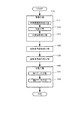
本発明に係る金属製多孔体1の製造方法は、図1に示すように、準備工程S10と、星形多角体形成工程S20と、成型工程S40とを含んでいる。具体的に、金属製多孔体1の製造方法は、筒状の金網からなる中間体32を準備する準備工程S10と、径方向の外側に突出する複数の凸部61と径方向の内側に窪んだ複数の凹部62とを中間体32の周方向に交互に形成して星形多角体60を形成する星形多角体形成工程S20と、星形多角体60の内周側と外周側とを拘束する型80に星形多角体60を入れて、星形多角体60の軸方向の一方から星形多角体60を圧縮する成型工程S40と、を含んでいる。[Basic process of metal porous body manufacturing method]
The manufacturing method of the metal
準備工程S10は、金属素線10を編み込んで筒状の金網を形成し、筒状の金網から内周部と外周部とを有する筒状の中間体32を形成する工程である。星形多角体形成工程S20は、径方向の外側に突出する複数の凹部62と、径方向の内側に窪んだ複数の凸部61とを周方向に交互に位置させて中間体32に形成して星形多角体60を形成する工程である。成型工程S40は、星形多角体60の内周側を拘束する芯材81と、星形多角体60の外周側を拘束する外周壁85とで構成された型80における、芯材81と外周壁85とで構成される空間に星形多角体60を入れて、星形多角体60の軸方向の一方から星形多角体60を圧縮する工程である。成型工程S40で用いる型80は、その軸方向の長さが異なる少なくとも2形態に変化可能に構成されている。
The preparation step S10 is a step of forming a cylindrical wire mesh by weaving the
成型工程S40は、軸方向の長さが長い形態の型80で星形多角体60を軸方向の一方から圧縮する第1プレス工程S41と、この第1プレス工程S41の後に、軸方向の長さが短い形態の型80で星形多角体60を軸方向の一方から、さらに圧縮する第2プレス工程S42と、を少なくとも有している。
The molding step S40 includes a first pressing step S41 for compressing the
なお、準備工程S10は、金網連続体形成工程S11、分割工程S12及び中間体形成工程S13を含めることができる。金網連続体形成工程S11は、金属素線10を編み込むことによって軸方向に連なる筒状の金網連続体30を形成する工程である。分割工程S12は、金網連続体30を、その軸方向に一定の長さを有する複数の筒状金網体31に分ける工程である。中間体形成工程S13は、筒状金網体31の側壁部を軸方向に折り返して中間体32を形成する工程である。
In addition, the preparation process S10 can include a wire mesh continuous body formation process S11, a division process S12, and an intermediate body formation process S13. The wire mesh continuum forming step S11 is a step of forming a cylindrical
また、金属製多孔体1の製造方法は、必要に応じて、上述した星形多角体形成工程S20と成型工程S40との間に、星形多角体圧縮工程S30を設けることもできる。この星形多角体圧縮工程S30は、星形多角体形成工程S20によって形成された星形多角体60を径方向の外側から内側に向けて押し付けることによって星形多角体60を中心側に圧縮して圧縮星形多角体60を形成する工程である。この星形多角体圧縮工程S30を設けた場合、成型工程S40では、圧縮星形多角体60が型80に入れられる。
Moreover, the manufacturing method of the metal
以上の工程を有する本発明に係る金属製多孔体1の製造方法によれば、金属製多孔体1の軸方向及び径方向に流れる流体の流量を、金属製多孔体1の周方向において均等にすることができ、かつ、強度を高くすることができるという特有の効果を奏する。
According to the manufacturing method of the metal
以下、本発明に係る金属製多孔体1の製造方法によって製造された金属製多孔体1について説明し、次いで、金属製多孔体1の製造方法の各工程の詳細を説明する。
Hereinafter, the metal
[金属製多孔体]
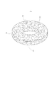
金属製多孔体1は、図2示すように、円筒状をなし、径方向の中央に空洞を有している。すなわち、金属製多孔体1は、外周面2と、内周面3と、軸方向の両端部をなす一対の端面4,5と、を有している。[Metal porous body]
As shown in FIG. 2, the metal
この金属製多孔体1は、金属素線10が編み込まれてなる筒状の金網を加工して製造されている。具体的に、金属製多孔体1は、金属素線10が編み込まれ、内周面と外周面とを有する筒状の金網を加工し、径方向の外側に向けて突出する複数の凸部61と径方向の内側に向けて窪んだ複数の凹部62とを周方向の交互に形成して星形多角体60を形成し、この星形多角体60の内周側と外周側とを拘束しながら、星形多角体60をその軸方向に圧縮することによって円筒状に形成されている。また、円環状の金網は、半径方向に重なる複数の金網の層を備えている。
The metal
(金属素線)
金属素線10は、例えば、ステンレス鋼又は軟鋼からなる線材が使用されている。ステンレス鋼の線材としては、例えば、JIS(Japanese Industrial Standards)規格のSUS304又はSUS316等からなる線材を挙げることができる。軟鋼線材としては、例えば、JIS規格のSWRM6、SWRCH6A等からなる線材を挙げることができる。金属素線10として軟鋼線材を用いる場合、銅、銅合金、亜鉛又はニッケルその他のめっきを施したものを用いることができる。ただし、金属線は上記の材料の他に、チタン、ニッケル又はアルミニウムその他の材料を用いることもできる。金属製多孔体1は、こうした材質の素線によって構成さているので、耐熱性、耐薬品性及び耐食性を備えている。(Metal wire)
For example, a wire made of stainless steel or mild steel is used as the
金属素線10は、その断面形状が円形の線材である。金属素線10の直径は、0.01mm以上、3mm以下である。ただし、金属素線10は、圧延されて、断面形状が楕円形又は略楕円形に形成された線材を用いてもよい。
The
(金属製多孔体)
金属製多孔体1は、上記の金属素線10からなる筒状の金網を加工することによって、空隙率が20%以上、90%以下であり、密度が7.75g/cm3以上、8.06g/cm3以下のステンレス鋼を用いた場合、嵩密度が0.5g/cm3以上、6.5g/cm3以下である。なお、「空隙率」とは、[(材料比重-製品密度)/材料比重]×100によって表すことができる製品の全容積に対する隙間の容積の割合のことであり、「嵩密度」とは、単位体積の質量=製品重量/製品体積によって表すことができる、製品の重量を製品の体積で除した単位体積あたりの質量のことである。(Metal porous body)
The metal
以上の金属製多孔体1は、流体に含まれる不純物を捕捉したり濾過したりするフィルター、流体の温度を下げる冷却部材、爆発音を吸収する消音部材、構造物を構成している部材同士の間に挟み込んで用いるスペーサ等に用いることができる。具体的に、金属製多孔体1は、エアバッグのインフレータ用フィルターとして利用することができる。金属製多孔体1をエアバッグのインフレータ用フィルターとして利用した場合、金属製多孔体1は、エアバッグが作動したときに生じる不純物を捕捉したり濾過したりする。また、金属製多孔体1は、エアバッグが作動したときの爆発音を消音する消音フィルターとして機能させたり、衝撃を吸収する衝撃吸収フィルターや防爆フィルターとして機能させたりすることができる。こうした、金属製多孔体1は、火薬を習慣的に燃焼させてガスを発生させるインフレータとは異なるシステムに用いることができる。
The metal
金属製多孔体1は、さらに、熱交換システムに用いることができる。すなわち、熱交換システムに用いられる熱交換媒体の通路に金属製多孔体1を組み込むことによって、金属製多孔体1は、再生器として機能させることができる。この場合、熱交換システムの高温側と低温側との間に配置された金属製多孔体1は、その周方向で熱を均等に伝えることによって、高い熱伝導率で熱を伝えることができる。
Furthermore, the metal
金属製多孔体1は、以上のように、高い負荷が作用する場所、衝撃的な負荷が作用する場所、温度が高い場所、及び温度変化が激しい場所等で用いることができる。
As described above, the metal
[金属製多孔体の製造方法]
上述したように、金属製多孔体1の製造方法は、図1に示すように、準備工程S10と、星形多角体形成工程S20と、成型工程S40とを含んでいる。また、金属製多孔体1の製造方法は、必要に応じて、上述した星形多角体圧縮工程S30を星形多角体形成工程S20と成型工程S40との間に設けることもできる。[Method for producing metal porous body]
As described above, the method for manufacturing the metal
〈準備工程〉
準備工程S10は、金属素線10を編み込んで筒状の金網を形成し、筒状の金網から内周部と外周部とを有する筒状の中間体32を形成する工程である。この準備工程S10は、図1に示すように、金網連続体形成工程S11、分割工程S12及び中間体形成工程S13を含めることができる。<Preparation process>
The preparation step S10 is a step of forming a cylindrical wire mesh by weaving the
(金網連続体形成工程)
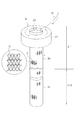
金網連続体形成工程S11は、金属素線10を編み込むことによって軸方向に連なる筒状の金網連続体30を形成する工程である。この金網連続体形成工程S11は、図3に示すように、金属素線10を編み機20に送り出し、送り出された金属素線10を編み機20で編み込むことによって筒状の金網連続体30を形成している。なお、図3は、説明を容易にするために、編み機20を模式的に示している。(Wire mesh continuum formation process)
The wire mesh continuum forming step S11 is a step of forming a cylindrical
編み機20は、金属素線10を編み込むための本体部21と、送り出された金属素線10を本体部21に案内するための案内針22とを備えている。本体部21は、径方向の中央に穴を有している。金網連続体30は、本体部21に設けられた穴から送り出される。
The
金網連続体30は、円筒状をなしている。また、金網連続体30は、その軸方向に連続している。なお、編み方は特に限定されない。図3に示す例は、A部を拡大して図示するように、素線をメリヤス編みして金網連続体30を形成している。
The
(分割工程)
分割工程S12は、図3に示すよう、編み機20から送り出された金網連続体30を、その軸方向に一定の長さを有する複数の筒状金網体31に分ける工程である。この分割工程S12によって形成される筒状金網体31は、図4に示すように、筒状をなしている。筒状金網体31の内部は空洞である。金網連続体30から筒状金網体31に分ける方法は、特に限定がない。分ける方法としては、編み機20から送り出された金網連続体30を所定の長さ毎に、刃物で切断して筒状金網体31を形成する方法を一例として挙げることができる。なお、筒状金網体31は、金属素線10が編み込まれることによって構成されている。編み方は、上述したように、特に限定はない。図4に例示した筒状金網体31は、A部を拡大して図示したように、素線をメリヤス編みして構成されている。(Division process)
The dividing step S12 is a step of dividing the wire mesh
(中間体形成工程)
中間体形成工程S13は、図5に示すように、筒状金網体31の側壁部31aを軸方向に折り返して、中間体32を形成する工程である。なお、図5は、中間体形成工程S13を模式的に示している。この中間体形成工程S13では、図5(A)から図5(D)に示すように、筒状金網体31の軸方向の一端から、側壁部31aを軸方向に一定の長さごとに外側に複数回折り返すことによって、図5(E)に示す中間体32を形成している。ただし、中間体32は、筒状金網体31の軸方向の一端から、筒状金網体31の側壁部31aを外側に丸ませて形成することもできる。この中間体形成工程S13によって形成された中間体32は、図5(E)に示すように、円環状の金網であり、外周部33と内周部34とを有している。また、円環状の金網である中間体32は、半径方向に重なる複数の金網の層を備えている。(Intermediate formation process)
As shown in FIG. 5, the intermediate body forming step S <b> 13 is a step of forming the
〈星形多角体形成工程〉
次に、図6から図12を参照して星形多角体60を形成する星形多角体形成工程S20について説明する。<Star polygon formation process>
Next, the star polygon forming step S20 for forming the
星形多角体形成工程S20は、径方向の外側に突出する複数の凸部61と、径方向の内側に窪んだ複数の凹部62とを、周方向に交互に位置させて中間体32に形成して星形多角体60を形成する工程である。この星形多角体形成工程S20は、図6に示す装置40を用いて星形多角体60を形成する第1タイプと、図12に示す装置50を用いて星形多角体60を形成する第2タイプとがある。
In the star polygon forming step S20, a plurality of
第1タイプの星形多角体形成工程S20は、図6に示すように、周方向に一定の間隔を空けて配置され、径方向に移動する複数の爪42を、中間体32の径方向の外側からこの中間体32に押し付けることによって星形多角体60を形成する。例えば、6個の凸部61と6個の凹部62を有する星形多角体60(図7参照)を形成する場合、星形多角体形成工程S20は、6個の爪42を備えた装置40(以下、単に「装置40」という。)を用いて実施される。この装置40は、例えば、ベース41と、ベース41上に配置された6個の爪42と、ベース41上に配置された受け部45とを有している。
As shown in FIG. 6, the first type star-shaped polygon forming step S <b> 20 is arranged with a plurality of
ベース41は、円盤状をなしている。このベース41は、星形多角体60として形成される中間体32が載せられる部材である。
The
6個の爪42は、ベース41上で周方向に均等に配置されている。各爪42は、その長手方向が径方向に向いてそれぞれ配されている。各爪42は、その長手方向の一端側に先細り形状の押し当て部43をそれぞれ有している。各爪42は、押し当て部43を径方向の内側に向けてそれぞれ配置されている。
The six
受け部45は、爪42によって押し付けられた中間体32を、中間体32の内側で受ける部位である。受け部45は、ベース41の中心に配置されている。この受け部45は、リング部46と、リング部46から径方向の外側に延びる仕切部47とを少なくとも備えている。仕切部47は、周方向の6箇所に設けられている。各仕切部47同士の周方向の間隔は一定である。
The receiving
6個の爪42は、周方向において、受け部45の仕切部47と仕切部47との間に位置している。各爪42が径方向の内側に移動したときに、各爪42の押し当て部43は、受け部の仕切部47と仕切部47との間に挿入される。
The six
この装置40は、星形多角体60を以下のように形成する。はじめに、図6(A)に示すように、装置40において、6個の爪42は径方向の外側に移動されている。中間体32は、各爪42に設けられた押し当て部43と受け部45との間にセットされる。中間体32が装置40にセットされた後、各爪42を径方向の内側に移動させ、押し当て部43を中間体32の外周部に突き当てて、図6(B)に示すように、中間体32を径方向の外側から内側に向けて押し付ける。
This
装置40は、6個の爪42を中間体32に押し付けることによって、中間体32の周方向の6箇所に、径方向の外側から内側に向かって窪む凹部62を形成する。一方、装置40は、爪42が押し付けられた部分同士の間の部分を、径方向の外側に向かって突出する凸部61として形成する。その結果、装置40は、図7に示す、星形多角体60を形成する。
By pressing the six
図7は星形多角体60の一例を示している。この星形多角体60は、径方向の外側に突出する凸部61を周方向の6箇所に備えている。また、星形多角体60は、径方向の内側に窪んだ凹部62を凸部61同士の間に備えている。この凹部62は、上述したように、爪42部が備える押し当て部43が押し付けられることによって形成された部位である。
FIG. 7 shows an example of a
なお、星形多角体形成工程S20で形成される星形多角体60は、6個の凸部61と6個の凹部62を有する形状には限定されない。凸部61の数と凹部62の数は、5個以下であってもよいし、7個以上であってもよい。その場合、装置に設ける爪42の数は、形成される星形多角体60の凹部62の数と凸部61の数とに一致される。例えば、凹部62の数及び凸部61の数が8この星形多角体60を形成する場合、8個の爪42が装置に設けられる。
The
第1タイプの星形多角体形成工程S20では、爪42が押し付けられた複数の部分に、径方向の内側に窪んだ凹部62を形成し、爪42が押し付けられた部分の間の複数の部分に径方向の外側に突出する凸部61を形成することができる。そのため、複数の爪42を一度に中間体32に押し付けることで星形多角体60を効率よく形成することができる。
In the first type star-shaped polygon forming step S20, a plurality of portions between the portions where the
第1タイプの星形多角体形成工程S20では、図8示す装置140(以下、「装置140」という。)を利用して、中間体32から図10に示す星形多角体160を形成してもよい。
In the first type star polygon forming step S20, the
装置140は、例えば、ベース141と、ベース141上に配置された6個の爪142と、ベース141上に配置された受け部145とを有している。ベース41は、例えば、円盤状をなしている。このベース141は、星形多角体160として形成される中間体32が載せられる部材である。6個の爪142は、その長手方向がベースの径方向に向いて、ベース141上で周方向に均等に配置されている。各爪142は、その長手方向の一端側に平板状の押し当て部143をそれぞれ有し、この押し当て部143を径方向の内側に向けている。
The
押し当て部143は、図9に示すように、垂直方向に対して斜めに傾けられている。なお、垂直方向は、中間体32の軸方向及び星形多角体160の軸方向に一致している。押し当て部143の垂直方向に対する傾斜角θは、5度以上、85度以下の範囲内で、中間体32の軸方向の長さに応じて適宜に設定するとよい。すなわち、星形多角体160が形成された際、軸方向のある領域では、凹部162が存在する周方向の部分に、軸方向の他の領域では、凸部161が存在する形態になるように、この傾斜角θは設定される。
As shown in FIG. 9, the
受け部145は、ベース141の中心に配置されており、爪142によって押し付けられた中間体32を、中間体32の内側で受ける部位である。受け部145の構造は、図6に示した装置40の受け部45とほぼ同様であり、リング部146と、リング部146から径方向の外側に延びる仕切部147とを少なくとも備えている。
The receiving
この装置140は、中間体32の径方向の外側から押し当て部143を中間体32の外周部に突き当て、中間体32を径方向の外側から内側に向けて押し付けることによって、図10に示す星形多角体を形成する。具体的には、装置140は、爪142の押し当て部143が押し付けられた位置に凹部162を形成すると共に、爪142の押し当て部143同士の間の位置に凸部161を形成して星形多角体160を形成する。
This
図10は、装置140により形成された星形多角体160の一例を示している。この星形多角体160は、径方向の外側に突出する凸部161を周方向の6箇所に備えている。また、星形多角体160は、径方向の内側に窪んだ凹部162を凸部161同士の間に備えている。
FIG. 10 shows an example of a
各凸部161及び各凹部162は、星形多角体160の軸方向に対して斜めに傾けられている。そのため、軸方向のある領域では、凹部162が存在する周方向の部分に、軸方向の他の領域では、凸部161が存在する。その結果、星形多角体160を平面視したとき、周方向の密度が均等になる。その結果、星形多角体160から形成された金属製多孔体1は、この金属製多孔体1の内部を流れる流体の圧力損失を周方向で均等にすることができると共に、強度を周方向で均等にすることができる。
Each
以上、斜めに傾けられた押し当て部143を有する爪142を用いて星形多角体160を形成する場合について説明した。ただし、軸方向に対して凸部161及び凹部162が斜めに傾けられた星形多角体160は、まず、図6に示す装置40を用いて図7に示す星形多角体60を形成し、次いで、星形多角体60を周方向に捩ることによって形成してもよい。
The case where the star-shaped
第2タイプの星形多角体形成工程S20は、図11に示すように、中間体32を周方向に移動させながら、中間体32の外側に配置された第1歯車51と、中間体32の内側に配置された第2歯車52とを噛み合わせることによって、星形多角体60を形成する。
As shown in FIG. 11, the second type star polygon forming step S <b> 20 includes the
第2タイプの星形多角体形成工程S20に用いられる装置50(以下、単に「装置50」という。)は、図11に示すように、2つの歯車51,52を備えている。なお、図11は、装置50の一例を模式的に示している。図11に示す装置50は、刃先円の直径が相対的に大きい第1歯車51と、刃先円の直径が相対的に小さい第2歯車52とを備えている。第1歯車51は、中間体32の外側に配置され、第2歯車52は、中間体32の内側に配置される。
The device 50 (hereinafter simply referred to as “
この装置50は、第1歯車51と第2歯車52との間の距離を長くしたり短くしたりすることができるように構成されている。ただし、第1歯車51と第2歯車52との距離を最も短くした場合でも、第1歯車51の歯と第2歯車52の歯とが接触せずに、一定の隙間が両者の間に形成される。すなわち、第1歯車51の歯が第2歯車52の歯と歯との間に位置するときに、第1歯車51の歯先と第2歯車52の歯元との間に一定の隙間が形成される。また、第1歯車51の歯面と第2歯車52の歯面との間にも一定の隙間が形成される。同様に、第2歯車52の歯が第1車の歯と歯との間に位置するときに、第2歯車52の歯先と第1歯車51の歯元との間に一定の隙間が形成されると共に、第1歯車51の歯面と第2歯車52の歯面との間にも一定の隙間が形成される。
The
第2タイプの星形多角体形成工程S20では、星形多角体60が装置50によって次のように形成される。
In the second type star polygon forming step S20, the
まず、第1歯車51と第2歯車52との距離が離された状態(図示せず)で、中間体32が第1歯車51と第2歯車52との間にセットされる。その際、第2歯車52は中間体32の内側に位置される。
First, the
次いで、第1歯車51と第2歯車52とを接近させ、中間体32を第1歯車51と第2歯車52とで挟み込む。中間体32が第1歯車51と第2歯車52とで挟み込まれることによって、中間体32の側壁部は、第1歯車51の歯先によって第2歯車52の歯元に向けて押し付けられると共に、第2歯車52の歯先によって第1歯車51の歯元に向けて押し付けられる。そのため、中間体32は、図11に示すように、中間体32の径方向の外側に向けて突出する凸部61と径方向の内側に向けて窪む凹部62とが形成される。
Next, the
その後、第1歯車51と第2歯車52とを回転させて、中間体32を周方向に移動させる。装置50において、第1歯車51と第2歯車52とが中間体32を挟み込んでいるため、第1歯車51及び第2歯車52は、その回転に伴って、中間体32を周方向に移動させ、凸部61と凹部62とを中間体32の周方向の全域にわたり交互に形成する。具体的には、第1歯車51の歯山に対応する、中間体の位置に凹部62を形成すると共に、第2歯車52の歯山に対応する、中間体の位置に凸部61を形成して星形多角体60を形成する。なお、図11に示す装置50で形成された星形多角体60は、図7に示すように、径方向の外側に突出する凸部61と内側に窪んだ凹部62とが、周方向の6箇所にそれぞれ形成される。
Thereafter, the
第2タイプの星形多角体形成工程S20では、二つの歯車51,52を噛み合わせるだけで星形多角体60を形成することできる。そのため、星形多角体60を簡素な装置で形成できる。また、歯の数が異なる歯車に交換するだけで、凹部62及び凸部61の数が異なる星形多角体60を形成することができる。
In the second type star polygon forming step S20, the
第2タイプの星形多角体形成工程S20では、図12に示すように、中間体32を周方向に移動させながら、2つのはすば歯車151,152を噛み合わせることによって、星形多角体160を形成してもよい。
In the second type star polygon forming step S20, as shown in FIG. 12, the two
この星形多角体形成工程S20に用いられる装置150(以下、単に「装置150」という。)は、図12に示すように、2つの歯車151,152を備えている。2つの歯車151,152は、歯山が各歯車の周方向に対して斜めに傾いたはすば歯車である。図12に示す装置150は、刃先円の直径が相対的に大きい第1歯車151と、刃先円の直径が相対的に小さい第2歯車152とを備えている。第1歯車151は、図示しない中間体の外側に配置され、第2歯車152は、図示しない中間体の内側に配置される。
A device 150 (hereinafter simply referred to as “
装置150は、中間体を第1歯車151と第2歯車152との間に挟み込ませ、第1歯車151及び第2歯車152を回転させることによって、図示しない中間体を周方向に移動させ、斜めに傾けられた凸部161及び凹部162を有する星形多角体160を形成する(図10参照)。具体的には、第1歯車151の歯山に対応する、中間体の位置に凹部162を形成すると共に、第2歯車152の歯山に対応する、中間体の位置に凸部161を形成して星形多角体160を形成する。
The
なお、第2タイプの星形多角体形成工程S20によって形多角体160を形成する場合、まず、図11に示す装置50を用いて図7に示す星形多角体60を形成し、次いで星形多角体60を周方向に捩ることによって形成してもよい。
In the case of forming the
〈星形多角体圧縮工程〉
次に、図13を参照して、星形多角体圧縮工程S30について説明する。なお、星形多角体圧縮工程S30は、必要に応じて設けられる工程であり、必須の工程ではない。<Star polygon compression process>
Next, the star polygon compression step S30 will be described with reference to FIG. The star polygon compression step S30 is a step provided as necessary, and is not an essential step.
星形多角体圧縮工程S30は、星形多角体形成工程S20によって形成された星形多角体60を径方向の外側から内側に向けて圧縮することによって圧縮星形多角体60,160を形成する。この星形多角体圧縮工程S30では、例えば、図13に示す装置70(以下、単に「装置70」という。)が用いられる。以下では、圧縮星形多角体60を形成する場合を例にして説明する。
In the star polygon compression step S30, the
この装置70は、円形のベース75と、ベース75上に配置された4本のアーム71とを備えている。各アーム71は、その長手方向がベース75の中心側から径方向の外側に延びる方向に向いてそれぞれ配置されている。4本のアーム71のうち、2本のアーム71は、ベース75の直径をなす線L1上に配されていて、ベース75の中心に対して対称をなしている。残りの2本のアーム71は、直径をなす線L1に対して直交する線L2上に配置されている。この2本のアーム71もベース75の中心に対して対称をなしている。
The
各アーム71の長手方向の一端は、押し当て面72を有している。押し当て面72は、円弧状にそれぞれ窪んでいる。この押し当て面72は、星形多角体60の外周面に押し当てる部分である。各アーム71は、この押し当て面72をベース75の中心に向けてそれぞれ配置されている。そして、4本のアーム71は径方向に移動するように構成されている。
One end of each
この星形多角体圧縮工程S30では、図13に示すように、星形多角体60がベース75の中心にセットされ、4本のアーム71をベース75の中心に向けて移動して、押し当て面72を星形多角体60の外周部に押し付けることによって、星形多角体60を径方向の内側に圧縮する。圧縮星形多角体60は、星形多角体60がアーム71によって径方向の内側に圧縮されることによって形成される。
In the star polygon compression step S30, as shown in FIG. 13, the
この星形多角体形成工程S20は、中間体32の内部に存在する空間を均等に分布させることができる。そのため、完成された金属製多孔体1の内部に存在する空間を周方向に均等にすることができる。また、この工程は、中間体32を構成する金網を塑性変形させている。そのため、強度を高めることができる。
This star polygon forming step S <b> 20 can evenly distribute the space existing inside the
〈成型工程〉
成型工程S40では、星形多角体60,160(圧縮星形多角体60,160を含む。)の内周側を拘束する芯材81と、星形多角体60,160の外周側を拘束する外周壁85とで構成された型80が用いられる。成型工程S40は、芯材81と外周壁85との間の空間に星形多角体60,160を入れ、星形多角体60,160の軸方向の一方から星形多角体60,160を圧縮することによって、図2に示す金属製多孔体1を成型する工程である。以下では、星形多角体60を成型する場合を例に説明する。<Molding process>
In the molding step S40, the core 81 that constrains the inner peripheral side of the
成型工程S40に用いられる型80は、図14に示すように、その軸方向の長さが異なる少なくとも2形態に変化可能に構成されている。そして、成型工程S40は、軸方向の長さが長い形態の型80で星形多角体60を軸方向の一方から圧縮する第1プレス工程S41と、第1プレス工程S41の後に、軸方向の長さが短い形態の型80で星形多角体60を軸方向の一方から星形多角体60を、さらに圧縮する第2プレス工程S42とを少なくとも有している(図1参照)。
As shown in FIG. 14, the
(型の構成)
型80は、図14に示すように、芯材81と外周壁85とを備えている。この型80は、芯材81と外周壁85との間に、成型される星形多角体60が入れられる空間を有している。型80の長手方向の一端80a側は、開かれており、型80の長手方向の他端80b側はブロック90等によって閉じられている。この成型工程S40では、図示しないアクチュエータが型80の長手方向における一端80a側のみに設けられる。成型工程S40では、一端80a側のみに設けられたアクチュエータが型80内の星形多角体60をプレスして金属製多孔体1を形成する。(Type structure)
As shown in FIG. 14, the
型80を構成する芯材81は、軸方向の長さが長い形態と、軸方向の長さが短い形態との2形態に変化させることができるように構成されている。具体的に、芯材81は、芯材本体部82と、型80の長手方向の長さを変化させるための芯材調整部83とから構成されている。長い形態の芯材81は、図14(A)及び図14(B)に示すように、芯材本体部82と芯材調整部83とが型80の長手方向につなげられた形態である。短い形態の芯材81は、図14(C)及び図14(D)に示すように、芯材調整部83が芯材81から取り外された形態である。
The
型80を構成する外周壁85は、芯材81と同様に、軸方向の長さが長い形態と、軸方向の長さが短い形態との2形態に変化させることができるように構成されている。外周壁85は、外周壁本体部86と外周壁調整部87とにより構成されている。長い形態の外周壁85は、図14(A)及び図14(B)に示すように、外周壁本体部86と外周壁調整部87とが型80の長手方向につなげられた形態である。短い形態の外周壁85は、図14(C)及び図14(D)に示すように、外周壁調整部87が外周壁85から取り外された形態である。
The outer
(成型工程の詳細)
成型工程S40の詳細について、図14を参照して説明する。この成型工程S40では、まず、図14(A)及び図14(B)に示す第1プレス工程S41が行われ、次いで、図14(C)及び図14(D)に示す第2プレス工程S42が行われる。(Details of molding process)
Details of the molding step S40 will be described with reference to FIG. In the molding step S40, first, a first press step S41 shown in FIGS. 14A and 14B is performed, and then a second press step S42 shown in FIGS. 14C and 14D. Is done.
第1プレス工程S41では、まず、図14(A)に示すように、芯材本体部82と芯材調整部83とが軸方向につなげられると共に、外周壁本体部86と外周壁調整部87とが軸方向につなげられ、長い形態の型80が形成される。また、型80の軸方向の一端80a側が開かれた状態にされる一方で、型80の軸方向の他端80bがブロック90で閉じられる。第1補助部材101、星形多角体60、及び第2補助部材102が、その順番にこの形態の型80の内部に挿入される。すなわち、型80の他端80b側かみて、第1補助部材101、星形多角体60、及び第2補助部材102がその順番に型80の内部に配置される。
In the first pressing step S41, first, as shown in FIG. 14A, the core body
次いで、図示しないアクチュエータが、型80の軸方向の一端80a側から型80の内部の第1補助部材101、星形多角体60、及び第2補助部材102をブロック90に向けて押すことによって、星形多角体60をプレスする。
Next, an actuator (not shown) pushes the first
次いで、図14(B)に示すように、第3補助部材103が型80の軸方向の一端80a側から型80の内部に挿入され、第2補助部材102の上に配置される。次いで、型80の軸方向の一端80a側から図示しないアクチュエータが、型80の内部の第1補助部材101、星形多角体60、第2補助部材102及び第3補助部材103をブロック90に向けて押すことによって、星形多角体60をさらにプレスする。
Next, as shown in FIG. 14B, the third
次に、第2プレス工程S42が行われる。第2プレス工程S42では、まず、図14(C)に示すように、型80から芯材調整部83及び外周壁調整部87が取り外される。そのため、型80は、芯材本体部82と外周壁本体部86とからなる短い形態になる。型80から芯材調整部83及び外周壁調整部87が取り外された状態では、ブロック90が配置された型80の軸方向の他端80b側において、第1補助部材101が型80から突出した状態になる。
Next, the second pressing step S42 is performed. In the second pressing step S42, first, as shown in FIG. 14C, the core
また、図14(C)に示すように、型80の軸方向の一端80a側には、押し付け用ジグ104が被せられる。この押し付け用ジグ104の周辺の下端面は、型80の一端80a側の端面に突き当てられ、押し付け用ジグ104の中央は、芯材81の先端が内部に挿入させる。
Further, as shown in FIG. 14C, a
次いで、図14(D)に示すように、図示しないアクチュエータが、型80の軸方向の一端80a側から押し付け用ジグ104の上から型80をブロック90に向けて押し付ける。型80がブロック90に向けて押し付けられることによって、星形多角体60がプレスされる。
Next, as shown in FIG. 14D, an actuator (not shown) presses the
星形多角体60がこの成型工程で上記のようにプレスされた場合、その外周面が外周壁85に拘束され、外周面は外周壁85の内面に沿って円形に形成される。また、内周面が芯材81に拘束され、内周面は円形に形成される。その結果、星形多角体60は、図2に示した円筒状の金属製多孔体1に成型される。
When the
この成型工程S40では、上述したように、型80が本体部82,86と調整部83,87とで構成されているので、調整部83,87を型80から取り外すことによって、型80の軸方向の長さが変化される。そのため、第1プレス工程S41及び第2プレス工程S42の両方の工程において、型80の軸方向の一方のみから星形多角体60をプレスすることによって、星形多角体60を型80の軸方向の両方からプレスすることと同等の圧縮作用を星形多角体60に与えることができる。すなわち、プレスするためのアクチュエータを型80の軸方向の一方側にのみ設けるだけで、型80の軸方向の両方にプレスするためのアクチュエータを設けた場合と同様の作用を得ることができる。
In this molding step S40, as described above, since the
以上、軸方向の長さが2形態に変化可能な型80を用いて成型工程S40を行う場合を例に説明した。しかしながら、軸方向の長さが3形態以上に変化可能な型を用いて成型工程S40を行うこともできる。
The case where the molding step S40 is performed using the
なお、この成型工程S40が終了した後、金属製多孔体1は、洗浄工程等を経て完成される。
In addition, after this shaping | molding process S40 is complete | finished, the metal
以上の工程を含む金属製多孔体1の製造方法で製造された金属製多孔体1は、高い強度を有する。また、金属製多孔体1の内部に存在する空隙が周方向に均等に分布される。そのため、流体が軸方向及び径方向に流れる際、流体は金属製多孔体1の周方向にて均等に流れる。
The metal
以下、本発明に係る金属製多孔体1の製造方法で製造された金属製多孔体1の詳細を実施例に基づいて具体的に説明する。
Hereinafter, the detail of the metal
本発明に係る金属製多孔体1の製造方法によって製作した金属製多孔体1と従来から使用されている金属製多孔体について、圧力損失の確認テスト及び圧縮強度の確認テストを行い、両者の比較を行った。なお、従来から使用されている金属製多孔体は、本発明の金属製多孔体1の製造方法の途中で形成される中間体をそのままプレスして完成させた金属製多孔体をいう。すなわち、従来から使用されている金属製多孔体は、星形多角体形成工程を経ないで完成したものである。
About the metal
[実施例1]
実施例1は、直径が0.36mmの白なまし鉄線の金属素線10を金網連続体形成工程、分割工程、中間体形成工程、星形多角体形成工程、及び成型工程を経て製作された金属製多孔体である。金網連続体形成工程では、金属素線10をメリヤス編みして金網連続体を形成した。金属製多孔体の軸方向の長さは10mmである。[Example 1]
Example 1 was manufactured through a wire mesh continuum forming process, a dividing process, an intermediate forming process, a star polygon forming process, and a molding process on a white annealed
[実施例2]
実施例2は、直径が0.70mmの白なまし鉄線の金属素線10を、実施例1と同様の製造方法で製作した金属製多孔体である。金属製多孔体の軸方向の長さは10mmである。[Example 2]
Example 2 is a metal porous body in which a white annealed
[比較例1]
比較例1は、実施例1と同じ金属素線1を金網連続体形成工程、分割工程、中間体形成工程、及び成型工程を経て製作された金属製多孔体である。金網連続体形成工程では、金属素線10をメリヤス編みして金網連続体を形成した。金属製多孔体の軸方向の長さは10mmである。[Comparative Example 1]
Comparative Example 1 is a metal porous body manufactured by subjecting the
[比較例2]
比較例2は、直径が0.70mmの白なまし鉄線の金属素線10を、比較例1と同様の製造方法で製作した金属製多孔体である。金属製多孔体の軸方向の長さは10mmである。[Comparative Example 2]
Comparative Example 2 is a metal porous body in which a white annealed
[圧力損失の確認テスト]
圧力損失の確認テストは、テストサンプルの径方向に流体を流した場合と、テストサンプルの軸方向に流体を流した場合とについて行った。[Pressure loss confirmation test]
The test for confirming the pressure loss was performed when the fluid was flowed in the radial direction of the test sample and when the fluid was flowed in the axial direction of the test sample.
〈径方向の圧力損失の確認テスト〉
径方向の確認テストは、テストサンプルの内周側から外周側にエアを流し、圧力損失を測定した。確認テストは、流量が50リットル/分、70リットル/分及び100リットル/分のエアを流して行った。また、確認テストは、図15に示すように、テストサンプルの周方向を4つの領域I,II,III,IVに分けて、各領域I,II,III,IVについて圧力損失を測定した。具体的には、金属製多孔体の軸方向の両側の端面を塞ぐと共に、周方向の1/4の部分を欠いたリング状のジグ110をテストサンプルの外周にはめ込み、ジグ110を周方向に1/4周ずつ回転させて行った。なお、確認テストは、実施例及び比較例ともに2個ずつ行った。<Diameter pressure loss confirmation test>
In the radial confirmation test, air was passed from the inner circumference side to the outer circumference side of the test sample, and the pressure loss was measured. The confirmation test was performed with air flow rates of 50 liters / minute, 70 liters / minute, and 100 liters / minute. In the confirmation test, as shown in FIG. 15, the circumferential direction of the test sample was divided into four regions I, II, III, and IV, and the pressure loss was measured for each region I, II, III, and IV. Specifically, the end faces on both sides in the axial direction of the metal porous body are closed, and a ring-shaped
評価は、各テストサンプルの4箇所の測定結果の平均値を算出し、平均値に対して最大で何%ばらついているかを求めて行った。なお、ここでいう最大のばらつきとは、平均値に対してプラス側にばらついた最大の値と、平均値に対してマイナス側にばらついた最大の値のうち、平均値との差が大きい方の値を意味する。 The evaluation was performed by calculating the average value of the measurement results at the four locations of each test sample and determining how much the maximum variation with respect to the average value. The maximum variation here is the one with the larger difference between the average value of the maximum value that varies on the positive side of the average value and the maximum value that varies on the negative side of the average value. Means the value of
(テスト結果)
表1は、確認テストのテスト結果を示した表である。(test results)
Table 1 is a table showing the test results of the confirmation test.

実施例1の第1サンプルは、表1に示すように、平均値に対するばらつきが、流量が50リットル/分のときに7.3%、70リットル/分のときに7.8%、100リットル/分のときに6.5%であった。また、実施例1の第2サンプルは、平均値に対するばらつきが、流量が50リットル/分のときに17.1%、70リットル/分のときに16.8%、100リットル/分のときに18.1%であった。第1サンプルと第2サンプルとの平均は、流量が50リットル/分のときに12.2%、70リットル/分のときに12.3%、100リットル/分のときに12.3%である。 As shown in Table 1, the first sample of Example 1 has a variation of 7.3% when the flow rate is 50 liters / minute, 7.8% when the flow rate is 70 liters / minute, and 100 liters. 6.5% at / min. In addition, the second sample of Example 1 shows a variation with respect to the average value of 17.1% when the flow rate is 50 liters / minute, 16.8% when the flow rate is 70 liters / minute, and 100 liters / minute. It was 18.1%. The average of the first and second samples is 12.2% when the flow rate is 50 liters / minute, 12.3% when the flow rate is 70 liters / minute, and 12.3% when the flow rate is 100 liters / minute is there.
実施例2の第1サンプルは、表1に示すように、平均値に対するばらつきが、流量が50リットル/分のときに14.6%、70リットル/分のときに12.0%、100リットル/分のときに11.6%であった。また、実施例2の第2サンプルは、平均値に対するばらつきが、流量が50リットル/分のときに7.2%、70リットル/分のときに8.8%、100リットル/分のときに11.0%であった。第1サンプルと第2サンプルとの平均は、流量が50リットル/分のときに10.9%、70リットル/分のときに10.4%、100リットル/分のときに11.3%である。 As shown in Table 1, the first sample of Example 2 has a variation with respect to the average value of 14.6% when the flow rate is 50 liters / minute, 12.0% when the flow rate is 70 liters / minute, and 100 liters. 11.6% at / min. In addition, the second sample of Example 2 shows a variation with respect to the average value of 7.2% when the flow rate is 50 liters / minute, 8.8% when the flow rate is 70 liters / minute, and 100 liters / minute. It was 11.0%. The average of the first sample and the second sample is 10.9% when the flow rate is 50 liters / minute, 10.4% when the flow rate is 70 liters / minute, and 11.3% when the flow rate is 100 liters / minute. is there.
一方、比較例1の第1サンプルは、平均値に対するばらつきが、流量が50リットル/分のときに37.5%、70リットル/分のときに38.1%、100リットル/分のときに33.8%であった。また、比較例1の第2サンプルは、平均値に対するばらつきが、流量が50リットル/分のときに27.0%、70リットル/分のときに27.2%、100リットル/分のときに26.8%であった。第1サンプルと第2サンプルとの平均は、流量が50リットル/分のときに32.2%、70リットル/分のときに32.6%、100リットル/分のときに30.3%である。 On the other hand, in the first sample of Comparative Example 1, the variation with respect to the average value is 37.5% when the flow rate is 50 liters / minute, 38.1% when 70 liters / minute, and 100 liters / minute. It was 33.8%. Further, the second sample of Comparative Example 1 shows a variation with respect to the average value when the flow rate is 27.0% when the flow rate is 50 liters / minute, 27.2% when the flow rate is 70 liters / minute, and 100 liters / minute. It was 26.8%. The average of the first and second samples is 32.2% when the flow rate is 50 liters / minute, 32.6% when the flow rate is 70 liters / minute, and 30.3% when the flow rate is 100 liters / minute. is there.
比較例2の第1サンプルは、平均値に対するばらつきが、流量が50リットル/分のときに38.3%、70リットル/分のときに34.3%、100リットル/分のときに34.5%であった。また、比較例2の第2サンプルは、平均値に対するばらつきが、流量が50リットル/分のときに22.0%、70リットル/分のときに26.1%、100リットル/分のときに27.8%であった。第1サンプルと第2サンプルとの平均は、流量が50リットル/分のときに30.1%、70リットル/分のときに30.2%、100リットル/分のときに31.2%である。 The first sample of Comparative Example 2 has a variation from the average value of 38.3% when the flow rate is 50 liters / minute, 34.3% when the flow rate is 70 liters / minute, and 34.3% when the flow rate is 100 liters / minute. It was 5%. Further, the second sample of Comparative Example 2 has a variation with respect to the average value of 22.0% when the flow rate is 50 liters / minute, 26.1% when 70 liters / minute, and 100 liters / minute. It was 27.8%. The average of the first and second samples is 30.1% at a flow rate of 50 liters / minute, 30.2% at 70 liters / minute, and 31.2% at 100 liters / minute. is there.
以上のテスト結果から分かるように、本発明の金属製多孔体1の製造方法で製作した金属製多孔体1は、従来の金属製多孔体よりも、流体が径方向に流れる場合の圧力損失が、周方向においてばらつきが小さい。
As can be seen from the above test results, the metal
〈軸方向の圧力損失の確認テスト〉
軸方向の確認テストは、テストサンプルの軸方向の一方の端面から他方の端面にエアを流し、圧力損失を測定した。確認テストは、流量が50リットル/分、70リットル/分及び100リットル/分のエアを流して行った。また、確認テストは、図16に示すように、テストサンプルの周方向を4つの領域I,II,III,IVに分けて、各領域I,II,III,IVについて圧力損失を測定した。具体的には、金属製多孔体の外周面と内周面とを塞ぐと共に、周方向の1/4の部分を欠いたリング状のジグ120で軸方向の両端面について周方向の3/4の部分を塞ぎ、周方向に1/4周ずつ回転させて行った。なお、確認テストは、実施例及び比較例ともに2個ずつ行った。<Axial pressure loss confirmation test>
In the axial confirmation test, air was passed from one end surface of the test sample in the axial direction to the other end surface, and pressure loss was measured. The confirmation test was performed with air flow rates of 50 liters / minute, 70 liters / minute, and 100 liters / minute. In the confirmation test, as shown in FIG. 16, the circumferential direction of the test sample was divided into four regions I, II, III, and IV, and pressure loss was measured for each region I, II, III, and IV. Specifically, the outer peripheral surface and the inner peripheral surface of the metal porous body are closed, and a ring-shaped
評価は、各テストサンプルの4箇所の測定結果の平均値を算出し、平均値に対して最大で何%ばらついているかを求めて行った。なお、ここでいう最大のばらつきとは、平均値に対してプラス側にばらついた最大の値と、平均値に対してマイナス側にばらついた最大の値のうち、平均値との差が大きい方の値を意味する。 The evaluation was performed by calculating the average value of the measurement results at the four locations of each test sample and determining how much the maximum variation with respect to the average value. The maximum variation here is the one with the larger difference between the average value of the maximum value that varies on the positive side of the average value and the maximum value that varies on the negative side of the average value. Means the value of
(テスト結果)
表2は、確認テストのテスト結果を示した表である。(test results)
Table 2 is a table showing the test results of the confirmation test.
実施例1の第1サンプルは、表2に示すように、平均値に対するばらつきが、流量が50リットル/分のときに11.9%、70リットル/分のときに16.3%、100リットル/分のときに14.9%であった。また、実施例1の第2サンプルは、平均値に対するばらつきが、流量が50リットル/分のときに13.9%、70リットル/分のときに8.0%、100リットル/分のときに7.6%であった。第1サンプルと第2サンプルとの平均は、流量が50リットル/分のときに12.9%、70リットル/分のときに12.2%、100リットル/分のときに11.2%である。 As shown in Table 2, the first sample of Example 1 shows variations of 11.9% when the flow rate is 50 liters / minute, 16.3% when the flow rate is 70 liters / minute, and 100 liters. 14.9% at / min. In addition, the second sample of Example 1 shows variations when the flow rate is 13.9% when the flow rate is 50 liters / minute, 8.0% when 70 liters / minute, and 100 liters / minute. It was 7.6%. The average of the first and second samples is 12.9% at a flow rate of 50 liters / minute, 12.2% at 70 liters / minute, and 11.2% at 100 liters / minute. is there.
実施例2の第1サンプルは、表2に示すように、平均値に対するばらつきが、流量が50リットル/分のときに11.5%、70リットル/分のときに16.5%、100リットル/分のときに13.4%であった。また、実施例2の第2サンプルは、平均値に対するばらつきが、流量が50リットル/分のときに20.8%、70リットル/分のときに8.9%、100リットル/分のときに8.8%であった。第1サンプルと第2サンプルとの平均は、流量が50リットル/分のときに16.2%、70リットル/分のときに12.7%、100リットル/分のときに11.1%である。 As shown in Table 2, the first sample of Example 2 shows variations of 11.5% when the flow rate is 50 liters / minute, 16.5% when the flow rate is 70 liters / minute, and 100 liters. 13.4% at / min. Further, the second sample of Example 2 shows a variation with respect to the average value of 20.8% when the flow rate is 50 liters / minute, 8.9% when 70 liters / minute, and 100 liters / minute. It was 8.8%. The average of the first and second samples is 16.2% at a flow rate of 50 liters / minute, 12.7% at 70 liters / minute, and 11.1% at 100 liters / minute. is there.
一方、比較例1の第1サンプルは、平均値に対するばらつきが、流量が50リットル/分のときに37.4%、70リットル/分のときに37.4%、100リットル/分のときに35.9%であった。また、比較例1の第2サンプルは、平均値に対するばらつきが、流量が50リットル/分のときに26.7%、70リットル/分のときに27.3%、100リットル/分のときに26.3%であった。第1サンプルと第2サンプルとの平均は、流量が50リットル/分のときに32.1%、70リットル/分のときに32.4%、100リットル/分のときに31.1%である。 On the other hand, in the first sample of Comparative Example 1, the variation with respect to the average value is 37.4% when the flow rate is 50 liters / minute, 37.4% when the flow rate is 70 liters / minute, and 100 liters / minute. It was 35.9%. In addition, the second sample of Comparative Example 1 shows variations of 26.7% when the flow rate is 50 liters / minute, 27.3% when the flow rate is 70 liters / minute, and 100 liters / minute when the flow rate is 100 liters / minute. It was 26.3%. The average of the first and second samples is 32.1% at a flow rate of 50 liters / minute, 32.4% at 70 liters / minute, and 31.1% at 100 liters / minute. is there.
比較例2の第1サンプルは、平均値に対するばらつきが、流量が50リットル/分のときに44.9%、70リットル/分のときに42.5%、100リットル/分のときに52.0%であった。また、比較例2の第2サンプルは、平均値に対するばらつきが、流量が50リットル/分のときに23.1%、70リットル/分のときに26.6%、100リットル/分のときに28.5%であった。第1サンプルと第2サンプルとの平均は、流量が50リットル/分のときに34.0%、70リットル/分のときに34.6%、100リットル/分のときに40.3%である。 The first sample of Comparative Example 2 has a variation with respect to the average value of 44.9% when the flow rate is 50 liters / minute, 42.5% when the flow rate is 70 liters / minute, and 52. 0%. Further, the second sample of Comparative Example 2 shows a variation with respect to the average value when the flow rate is 23.1% when the flow rate is 50 liters / minute, 26.6% when the flow rate is 70 liters / minute, and 100 liters / minute. It was 28.5%. The average of the first and second samples is 34.0% at a flow rate of 50 liters / minute, 34.6% at a flow rate of 70 liters / minute, and 40.3% at 100 liters / minute. is there.
以上のテスト結果に示されているように、本発明の金属製多孔体1の製造方法で製作した金属製多孔体1は、従来の金属製多孔体よりも、流体が軸方向に流れる場合の圧力損失が、周方向においてばらつきが小さい。
As shown in the above test results, the metal
[圧縮強度の確認テスト]
圧縮強度の確認テストは、テンシロン万能試験機(株式会社エー・アンド・デイ社製RTG−1310)を用いてテストサンプルを軸方向に圧縮し、圧縮荷重と変位との関係を測定した。確認テストは、テストサンプルを圧縮する速度を5mm/分とし、荷重限界を5000ニュートンとして行った。なお、確認テストは、実施例1,2及び比較例1,2のいずれについても1つずつ行った。[Confirmation test of compressive strength]
In the compressive strength confirmation test, a test sample was compressed in the axial direction using a Tensilon universal testing machine (RTG-1310 manufactured by A & D Co., Ltd.), and the relationship between the compression load and displacement was measured. In the confirmation test, the test sample was compressed at a speed of 5 mm / min, and the load limit was set at 5000 Newton. The confirmation test was performed one by one for each of Examples 1 and 2 and Comparative Examples 1 and 2.
(テスト結果)
図17に示すグラフは、実施例1と比較例1とのテスト結果を示している。このグラフの横軸は変位を表し、グラフの縦軸は圧縮荷重を表している。また、実線は、実施例1を表し、破線は、比較例1を表している。(test results)
The graph shown in FIG. 17 shows the test results of Example 1 and Comparative Example 1. The horizontal axis of this graph represents displacement, and the vertical axis of the graph represents compression load. Further, the solid line represents Example 1, and the broken line represents Comparative Example 1.
実施例1は、図17のグラフの実線に示すように、荷重が1000ニュートンのときでも、変位が0.5mmよりも小さく、荷重が2000ニュートンのときに、変位が約0.5mmになっている。そして、荷重が5000ニュートンのときに、変位が約0.82mmである。 In Example 1, as shown by the solid line in the graph of FIG. 17, even when the load is 1000 Newton, the displacement is smaller than 0.5 mm, and when the load is 2000 Newton, the displacement is about 0.5 mm. Yes. And when a load is 5000 Newtons, a displacement is about 0.82 mm.
一方、比較例1は、図17のグラフの破線に示すように、実施例1のグラフよりも全体的に右側にシフトしている。具体的には、荷重が1000ニュートンのときに、変位が既に約0.5mmに達している。また、荷重が5000ニュートンのときに、変位が約0.94mmである。 On the other hand, as shown by the broken line in the graph of FIG. 17, the comparative example 1 is shifted to the right as a whole from the graph of the first example. Specifically, when the load is 1000 Newton, the displacement has already reached about 0.5 mm. Further, when the load is 5000 Newton, the displacement is about 0.94 mm.
図18に示すグラフは、実施例2と比較例2とのテスト結果を示している。このグラフの横軸は変位を表し、グラフの縦軸は圧縮荷重を表している。また、実線は、実施例2を表し、破線は、比較例2を表している。 The graph shown in FIG. 18 shows the test results of Example 2 and Comparative Example 2. The horizontal axis of this graph represents displacement, and the vertical axis of the graph represents compression load. Further, the solid line represents Example 2, and the broken line represents Comparative Example 2.
実施例2は、図18のグラフの実線に示すように、荷重が1000ニュートンのときでも、変位が0.5mmよりも小さく、荷重が2000ニュートンのときに、変位が約0.5mmになっている。そして、荷重が5000ニュートンのときに、変位が約0.80mmである。 In Example 2, as shown by the solid line in the graph of FIG. 18, even when the load is 1000 Newton, the displacement is smaller than 0.5 mm, and when the load is 2000 Newton, the displacement is about 0.5 mm. Yes. When the load is 5000 Newton, the displacement is about 0.80 mm.
一方、比較例2は、図18のグラフの破線に示すように、実施例2のグラフよりも全体的に右側にシフトしている。具体的には、荷重が1000ニュートンのときに、変位が既に約0.5mmに達している。また、荷重が5000ニュートンのときに、変位が約0.94mmである。 On the other hand, the comparative example 2 is shifted to the right as a whole as compared with the graph of the example 2 as shown by the broken line in the graph of FIG. Specifically, when the load is 1000 Newton, the displacement has already reached about 0.5 mm. Further, when the load is 5000 Newton, the displacement is about 0.94 mm.
以上のテスト結果に示されているように、本発明に係る金属製多孔体1の製造方法で製作した金属製多孔体1と、従来の金属製多孔体とを同じ条件で圧縮した場合、本発明の金属製多孔体1の製造方法で製作した金属製多孔体1は、従来の金属製多孔体よりも変形量が小さく、強度が高い。
As shown in the above test results, when the metal
また、本発明に係る金属製多孔体の製造方法で製造した金属製多孔体1及び従来の製造方法で製造した金属製多孔体を切断し、断面を顕微鏡で拡大して詳細に調査することによって両者の差異を検討した。本願の出願時点では、金属製多孔体の内部構造を調査する場合、過大な経済的支出を伴わず、過大な時間を費やさないで調査する方法としては、金属製多孔体を切断し、断面を顕微鏡で拡大して調査することが実際的な方法である。
In addition, by cutting the metal
金属製多孔体を切断し、断面を顕微鏡で拡大して調査した結果、本願発明に係る製造方法で製造した金属製多孔体の内部構造と従来の製造方法で製造した金属製多孔体の内部構造の差異を確認することができなかった。 As a result of cutting the metal porous body and enlarging the cross section with a microscope, the internal structure of the metal porous body manufactured by the manufacturing method according to the present invention and the internal structure of the metal porous body manufactured by the conventional manufacturing method The difference of could not be confirmed.
1 金属製多孔体
2 外周面
3 内周面
4 端面
5 端面
10 金属素線
20 編み機
21 編み機の本体部
22 案内針
30 金網連続体
31 筒状金網体
32 中間体
33 中間体の外周部
34 中間体の内周部
40,140 第1タイプの星形多角体形成工程に用いられる装置
41,141 ベース
42,142 爪
43,143 押し当て部
45,145 受け部
46,146 リング部
47,147 仕切部
50,150 第2タイプの星形多角体形成工程に用いられる装置
51,151 第1歯車
52,152 第2歯車
60,160 星形多角体
61,161 凸部
62,162 凹部
70 星形多角体圧縮工程に用いられる装置
71 アーム
72 押し当て面
75 ベース
80 型
80a 一端
80b 他端
81 芯材
82 芯材本体部
83 芯材調整部
85 外周壁
86 外周壁本体部
87 外周壁調整部
90 ブロック
101 第1補助部材
102 第2補助部材
103 第3補助部材
104 押し付け用ジグDESCRIPTION OF
Claims (10)
径方向の外側に突出する複数の凸部と前記径方向の内側に窪んだ複数の凹部とを前記中間体の周方向に交互に形成して星形多角体を形成する製造中間過程である星形多角体形成工程と、
前記星形多角体の内周側と外周側とを拘束する型に該星形多角体を入れて、該星形多角体の軸方向の一方から該星形多角体を圧縮し、前記星形多角体の内周側と外周側の凹凸を取り去り円形に形成する成型工程と、を少なくとも有している、金属製多孔体の製造方法。 A preparation step of preparing an intermediate body made of a tubular wire mesh;
A star which is an intermediate manufacturing process for forming a star polygon by alternately forming a plurality of convex portions protruding radially outward and a plurality of concave portions recessed radially inward in the circumferential direction of the intermediate body Forming a polygonal shape;
The star polygon is put into a mold that constrains the inner circumference side and the outer circumference side of the star polygon, and the star polygon is compressed from one side in the axial direction of the star polygon. A method for producing a metal porous body, comprising at least a molding step of removing irregularities on an inner peripheral side and an outer peripheral side of a polygon to form a circular shape.
前記成型工程で用いられる前記型は、前記星形多角体の内周側を拘束する芯材と前記星形多角体の外周側を拘束する外周壁とで構成され、
前記型は、その軸方向の長さが異なる少なくとも2形態に変化可能に構成され、
前記成型工程は、軸方向の長さが長い形態の前記型で前記星形多角体を前記軸方向の一方から圧縮する第1プレス工程と、該第1プレス工程の後に、軸方向の長さが短い形態の前記型で前記星形多角体を軸方向の一方から、さらに圧縮する第2プレス工程と、を少なくとも有している、請求項1に記載の金属製多孔体の製造方法。 In the preparation step, a metal wire is knitted to form a cylindrical wire mesh, and a cylindrical intermediate body having an inner peripheral portion and an outer peripheral portion is formed from the wire mesh,
The mold used in the molding step is composed of a core material that restrains the inner peripheral side of the star polygon and an outer peripheral wall that restrains the outer periphery side of the star polygon,
The mold is configured to be changeable into at least two forms having different axial lengths,
The molding step includes a first pressing step of compressing the star polygon from one of the axial directions with the mold having a long axial length, and an axial length after the first pressing step. 2. The method for producing a metal porous body according to claim 1, further comprising: a second pressing step of further compressing the star polygon from one side in the axial direction with the mold having a short shape.
前記第1プレス工程では、前記星形多角体を、前記長さ調整部が前記本体部に組み合わされた前記芯材と前記外周壁とからなる前記型を用いて圧縮し、
前記第2プレス工程では、前記星形多角体を、前記長さ調整部が前記本体部から取り外された前記芯材と前記外周壁とからなる前記型を用いて圧縮する、請求項2に記載の金属製多孔体の製造方法。 The core member and the outer peripheral wall are each composed of a main body part and a length adjusting part that is removable from the main body part,
In the first pressing step, the star polygon is compressed using the mold composed of the core member and the outer peripheral wall in which the length adjusting portion is combined with the main body portion,
The said 2nd press process WHEREIN: The said star-shaped polygon is compressed using the said type | mold which consists of the said core material and the said outer peripheral wall from which the said length adjustment part was removed from the said main-body part. Of manufacturing a porous metal body.
前記金網連続体を、前記軸方向に一定の長さを有する複数の筒状金網体に分ける分割工程と、
前記筒状金網体の側壁部を軸方向に折り返して、前記中間体を形成する中間体形成工程と、を含む、請求項1に記載の金属多孔体の製造方法。 The preparation step is a wire mesh continuum forming step of forming a cylindrical wire mesh continuum continuous in the axial direction by weaving metal strands;
Dividing the wire mesh continuous body into a plurality of cylindrical wire mesh bodies having a certain length in the axial direction;
The manufacturing method of the metal porous body of Claim 1 including the intermediate body formation process which folds the side wall part of the said cylindrical metal-mesh body to an axial direction, and forms the said intermediate body.
前記成型工程では、前記圧縮星形多角体が前記型に入れられる、請求項1〜7のいずれか1項に記載の金属製多孔体の製造方法。 A star that compresses the star polygon to the center side by pressing the star polygon formed by the star polygon forming step inward from the outside in the radial direction to form a compressed star polygon. Having a polygonal compression process,
The method for producing a metal porous body according to any one of claims 1 to 7, wherein in the molding step, the compressed star polygon is placed in the mold.
前記星形多角体の内周側と外周側とが拘束され、該星形多角体がその軸方向に圧縮されることにより円筒構造に形成されている、金属製多孔体。 A star-shaped polygon formed by alternately providing a plurality of convex portions protruding outward in the radial direction and a plurality of concave portions recessed inward in the radial direction is provided between the inner peripheral surface and the outer peripheral surface. The star polygon is formed from an annular wire mesh formed by braiding metal strands;
A metallic porous body formed into a cylindrical structure by restraining an inner peripheral side and an outer peripheral side of the star polygon and compressing the star polygon in the axial direction.
Applications Claiming Priority (5)
| Application Number | Priority Date | Filing Date | Title |
|---|---|---|---|
| JP2014164101 | 2014-08-12 | ||
| JP2014164101 | 2014-08-12 | ||
| JP2014174925 | 2014-08-29 | ||
| JP2014174925 | 2014-08-29 | ||
| PCT/JP2015/072856 WO2016024616A1 (en) | 2014-08-12 | 2015-08-12 | Porous metal body manufacturing method and porous metal body |
Publications (2)
| Publication Number | Publication Date |
|---|---|
| JPWO2016024616A1 JPWO2016024616A1 (en) | 2017-04-27 |
| JP6133513B2 true JP6133513B2 (en) | 2017-05-24 |
Family
ID=55304243
Family Applications (1)
| Application Number | Title | Priority Date | Filing Date |
|---|---|---|---|
| JP2016542605A Active JP6133513B2 (en) | 2014-08-12 | 2015-08-12 | Method for producing metal porous body and metal porous body |
Country Status (8)
| Country | Link |
|---|---|
| US (1) | US9968984B2 (en) |
| EP (1) | EP3138641B1 (en) |
| JP (1) | JP6133513B2 (en) |
| KR (1) | KR101745929B1 (en) |
| CN (1) | CN106413936B (en) |
| MX (1) | MX355583B (en) |
| PL (1) | PL3138641T3 (en) |
| WO (1) | WO2016024616A1 (en) |
Families Citing this family (3)
| Publication number | Priority date | Publication date | Assignee | Title |
|---|---|---|---|---|
| DE102017108798A1 (en) * | 2017-04-25 | 2018-10-25 | Trw Airbag Systems Gmbh | GAS GENERATOR, GASSACK MODULE, VEHICLE SAFETY SYSTEM, AND METHOD FOR CLEANING A PYROTECHNICALLY GENERATED GAS |
| JP7579670B2 (en) | 2020-10-16 | 2024-11-08 | 株式会社Pillar | Method for manufacturing metal mesh body |
| US12473670B2 (en) * | 2023-05-16 | 2025-11-18 | The Hong Kong University Of Science And Technology | Woven quadrilateral mesh origami structures and related functional materials |
Family Cites Families (28)
| Publication number | Priority date | Publication date | Assignee | Title |
|---|---|---|---|---|
| US629245A (en) * | 1898-07-21 | 1899-07-18 | Salomon Frank | Apparatus for producing ribbed or corrugated tubes. |
| US1964289A (en) * | 1933-09-28 | 1934-06-26 | Nat Standard Co | Manufacture of conduits |
| US2205893A (en) * | 1937-09-03 | 1940-06-25 | Gen Electric | Method of corrugating a heatradiating tube |
| US2334263A (en) * | 1941-06-03 | 1943-11-16 | Metal Textile Corp | Foraminous body and method of producing the same |
| US2680284A (en) * | 1950-11-03 | 1954-06-08 | Barry Corp | Method of making dampers for vibration isolators |
| US3407638A (en) * | 1966-03-24 | 1968-10-29 | Kinefac Corp | Method for forming serrated or corrugated hollow tubes |
| US3690606A (en) * | 1968-05-27 | 1972-09-12 | Pall Corp | Anisometric compressed and bonded multilayer knitted wire mesh composites |
| US3630058A (en) * | 1970-01-27 | 1971-12-28 | Frances E Reed | Process and apparatus for forming tubes with spiral corrugations |
| US3824826A (en) * | 1971-03-30 | 1974-07-23 | J Charvet | Method and apparatus for forming flexible corrugated members |
| JPS52145614A (en) * | 1976-05-28 | 1977-12-03 | Chuo Hatsujo Kk | Exhaust gas purifying catalytic honey comb support cushion body and method of forming |
| US4470290A (en) * | 1981-09-04 | 1984-09-11 | Anderson-Cook, Inc. | Thin-wall sleeve forming |
| US4683010A (en) | 1985-10-01 | 1987-07-28 | Acs Industries, Inc. | Compacted wire seal and method of forming same |
| JPH0722664B2 (en) * | 1989-11-08 | 1995-03-15 | 日本碍子株式会社 | Gas filter and manufacturing method thereof |
| US5849054A (en) * | 1995-10-31 | 1998-12-15 | Nippon Reinz Co., Ltd. | Filter for an inflator |
| JP3218200B2 (en) * | 1996-04-08 | 2001-10-15 | ダイセル化学工業株式会社 | Coolant for gas generator for airbag |
| US6234521B1 (en) * | 1996-04-08 | 2001-05-22 | Daicel Chemical Industries, Ltd. | Airbag inflator and an airbag apparatus |
| JP3784161B2 (en) | 1998-01-12 | 2006-06-07 | 日本ラインツ株式会社 | Inflator filter and manufacturing method thereof |
| GB2333470B (en) * | 1998-01-23 | 2002-05-01 | Acs Ind Inc | Filter with stiffening ribs |
| JPH11244629A (en) | 1998-02-26 | 1999-09-14 | Nippon Reinz Co Ltd | Reproduction of filter for inflator |
| US6277166B2 (en) * | 1999-03-31 | 2001-08-21 | Acs Industries Inc. | Filter with stiffening ribs |
| JP3481890B2 (en) * | 1999-09-08 | 2003-12-22 | 東亜鉄網株式会社 | Compression molded product and method for producing the same |
| US6866693B2 (en) * | 2002-06-06 | 2005-03-15 | Shuetsutechnica Co., Ltd. | Washable air filter for internal combustion engine |
| US8337182B2 (en) * | 2006-10-03 | 2012-12-25 | Schlumberger Technology Corporation | Skinning of progressive cavity apparatus |
| US7637979B2 (en) * | 2007-04-26 | 2009-12-29 | Mitsui Engineering & Shipbuilding Co., Ltd. | Fabrication method of diesel particular filter element |
| JP2011218400A (en) * | 2010-04-08 | 2011-11-04 | Cordialtec:Kk | Compression molding and method of manufacturing the same |
| JP2012120954A (en) * | 2010-12-06 | 2012-06-28 | Cordialtec:Kk | Metal wire molded body and filter |
| JP2013019347A (en) * | 2011-07-12 | 2013-01-31 | Nihon Glassfiber Industrial Co Ltd | Metal wire compressed body |
| JP2014008451A (en) * | 2012-06-29 | 2014-01-20 | Calsonic Kansei Corp | Method for producing metallic catalyst carrier |
-
2015
- 2015-08-12 KR KR1020167032538A patent/KR101745929B1/en active Active
- 2015-08-12 PL PL15831367T patent/PL3138641T3/en unknown
- 2015-08-12 US US15/314,835 patent/US9968984B2/en active Active
- 2015-08-12 WO PCT/JP2015/072856 patent/WO2016024616A1/en not_active Ceased
- 2015-08-12 MX MX2016016332A patent/MX355583B/en active IP Right Grant
- 2015-08-12 CN CN201580028740.9A patent/CN106413936B/en active Active
- 2015-08-12 JP JP2016542605A patent/JP6133513B2/en active Active
- 2015-08-12 EP EP15831367.6A patent/EP3138641B1/en active Active
Also Published As
| Publication number | Publication date |
|---|---|
| PL3138641T3 (en) | 2018-07-31 |
| CN106413936B (en) | 2018-01-02 |
| EP3138641A1 (en) | 2017-03-08 |
| US9968984B2 (en) | 2018-05-15 |
| EP3138641B1 (en) | 2018-01-10 |
| US20170197242A1 (en) | 2017-07-13 |
| KR101745929B1 (en) | 2017-06-12 |
| JPWO2016024616A1 (en) | 2017-04-27 |
| MX2016016332A (en) | 2017-03-31 |
| KR20160143855A (en) | 2016-12-14 |
| CN106413936A (en) | 2017-02-15 |
| EP3138641A4 (en) | 2017-06-14 |
| WO2016024616A1 (en) | 2016-02-18 |
| MX355583B (en) | 2018-04-24 |
Similar Documents
| Publication | Publication Date | Title |
|---|---|---|
| JP6133513B2 (en) | Method for producing metal porous body and metal porous body | |
| JP2017044228A (en) | Rack, and its manufacturing method | |
| JP6394254B2 (en) | Manufacturing method and manufacturing apparatus for expanded diameter pipe parts | |
| JP5934062B2 (en) | Spinning method | |
| JP6300871B2 (en) | Drawing machine and twist bar manufacturing method | |
| WO2013179384A1 (en) | Wire saw | |
| JP2013536378A (en) | Hollow gear ring and manufacturing method thereof | |
| WO2014138512A2 (en) | Wire mesh filter with improved wire and method of making the wire | |
| CN102553357A (en) | Metal line shaping body and filter | |
| US20100275443A1 (en) | Method of producing exhaust-gas carrying devices, in particular exhaust-gas cleaning devices | |
| JP6022275B2 (en) | Cylindrical filter manufacturing method and cylindrical filter | |
| JP2017042810A (en) | Manufacturing method of coil spring and manufacturing device of coil spring | |
| JP5940865B2 (en) | Tapering forging method | |
| KR101009901B1 (en) | Wire mesh filter manufacturing device | |
| JP5756618B2 (en) | Manufacturing method of purification equipment for automobile | |
| JP6279045B2 (en) | Cylindrical filter manufacturing method and cylindrical filter | |
| JP2003326322A (en) | Method of manufacturing hollow member and catalytic converter having catalyst container formed of hollow member | |
| JP7313681B2 (en) | HOLLOW CYLINDER AND METHOD FOR MANUFACTURING HOLLOW CYLINDER | |
| JP2015200219A (en) | Catalytic converter manufacturing method and catalytic converter | |
| WO2022079883A1 (en) | Hollow cylindrical body and method for manufacturing hollow cylindrical body | |
| JP6182076B2 (en) | Metal wire compact and method for producing the same | |
| JP2018126782A (en) | Manufacturing method of metallic hollow sphere | |
| JP2013006189A (en) | Device and method for manufacturing hollow rack bar | |
| JP4495187B2 (en) | CROWNING GEAR MANUFACTURING METHOD | |
| JPH0722664B2 (en) | Gas filter and manufacturing method thereof |
Legal Events
| Date | Code | Title | Description |
|---|---|---|---|
| A621 | Written request for application examination |
Free format text: JAPANESE INTERMEDIATE CODE: A621 Effective date: 20161021 |
|
| A871 | Explanation of circumstances concerning accelerated examination |
Free format text: JAPANESE INTERMEDIATE CODE: A871 Effective date: 20161021 |
|
| A975 | Report on accelerated examination |
Free format text: JAPANESE INTERMEDIATE CODE: A971005 Effective date: 20161121 |
|
| A131 | Notification of reasons for refusal |
Free format text: JAPANESE INTERMEDIATE CODE: A131 Effective date: 20161213 |
|
| A521 | Request for written amendment filed |
Free format text: JAPANESE INTERMEDIATE CODE: A523 Effective date: 20170213 |
|
| A131 | Notification of reasons for refusal |
Free format text: JAPANESE INTERMEDIATE CODE: A131 Effective date: 20170307 |
|
| A521 | Request for written amendment filed |
Free format text: JAPANESE INTERMEDIATE CODE: A523 Effective date: 20170324 |
|
| TRDD | Decision of grant or rejection written | ||
| A01 | Written decision to grant a patent or to grant a registration (utility model) |
Free format text: JAPANESE INTERMEDIATE CODE: A01 Effective date: 20170411 |
|
| A61 | First payment of annual fees (during grant procedure) |
Free format text: JAPANESE INTERMEDIATE CODE: A61 Effective date: 20170419 |
|
| R150 | Certificate of patent or registration of utility model |
Ref document number: 6133513 Country of ref document: JP Free format text: JAPANESE INTERMEDIATE CODE: R150 |
|
| R250 | Receipt of annual fees |
Free format text: JAPANESE INTERMEDIATE CODE: R250 |
|
| R250 | Receipt of annual fees |
Free format text: JAPANESE INTERMEDIATE CODE: R250 |
|
| R250 | Receipt of annual fees |
Free format text: JAPANESE INTERMEDIATE CODE: R250 |
|
| R250 | Receipt of annual fees |
Free format text: JAPANESE INTERMEDIATE CODE: R250 |