EP3138441A1 - Dämpfungsvorrichtung zur dämpfung der öffnungsbewegung eines bewegbaren möbelteils - Google Patents
Dämpfungsvorrichtung zur dämpfung der öffnungsbewegung eines bewegbaren möbelteils Download PDFInfo
- Publication number
- EP3138441A1 EP3138441A1 EP16184015.2A EP16184015A EP3138441A1 EP 3138441 A1 EP3138441 A1 EP 3138441A1 EP 16184015 A EP16184015 A EP 16184015A EP 3138441 A1 EP3138441 A1 EP 3138441A1
- Authority
- EP
- European Patent Office
- Prior art keywords
- damper
- base unit
- movable
- damping
- damping device
- Prior art date
- Legal status (The legal status is an assumption and is not a legal conclusion. Google has not performed a legal analysis and makes no representation as to the accuracy of the status listed.)
- Granted
Links
Images

Classifications
-
- E—FIXED CONSTRUCTIONS
- E05—LOCKS; KEYS; WINDOW OR DOOR FITTINGS; SAFES
- E05F—DEVICES FOR MOVING WINGS INTO OPEN OR CLOSED POSITION; CHECKS FOR WINGS; WING FITTINGS NOT OTHERWISE PROVIDED FOR, CONCERNED WITH THE FUNCTIONING OF THE WING
- E05F3/00—Closers or openers with braking devices, e.g. checks; Construction of pneumatic or liquid braking devices
- E05F3/02—Closers or openers with braking devices, e.g. checks; Construction of pneumatic or liquid braking devices with pneumatic piston brakes
-
- A—HUMAN NECESSITIES
- A47—FURNITURE; DOMESTIC ARTICLES OR APPLIANCES; COFFEE MILLS; SPICE MILLS; SUCTION CLEANERS IN GENERAL
- A47B—TABLES; DESKS; OFFICE FURNITURE; CABINETS; DRAWERS; GENERAL DETAILS OF FURNITURE
- A47B88/00—Drawers for tables, cabinets or like furniture; Guides for drawers
- A47B88/40—Sliding drawers; Slides or guides therefor
- A47B88/473—Braking devices, e.g. linear or rotational dampers or friction brakes; Buffers; End stops
-
- A—HUMAN NECESSITIES
- A47—FURNITURE; DOMESTIC ARTICLES OR APPLIANCES; COFFEE MILLS; SPICE MILLS; SUCTION CLEANERS IN GENERAL
- A47B—TABLES; DESKS; OFFICE FURNITURE; CABINETS; DRAWERS; GENERAL DETAILS OF FURNITURE
- A47B88/00—Drawers for tables, cabinets or like furniture; Guides for drawers
- A47B88/40—Sliding drawers; Slides or guides therefor
- A47B88/49—Sliding drawers; Slides or guides therefor with double extensible guides or parts
- A47B88/493—Sliding drawers; Slides or guides therefor with double extensible guides or parts with rollers, ball bearings, wheels, or the like
-
- E—FIXED CONSTRUCTIONS
- E05—LOCKS; KEYS; WINDOW OR DOOR FITTINGS; SAFES
- E05F—DEVICES FOR MOVING WINGS INTO OPEN OR CLOSED POSITION; CHECKS FOR WINGS; WING FITTINGS NOT OTHERWISE PROVIDED FOR, CONCERNED WITH THE FUNCTIONING OF THE WING
- E05F3/00—Closers or openers with braking devices, e.g. checks; Construction of pneumatic or liquid braking devices
- E05F3/04—Closers or openers with braking devices, e.g. checks; Construction of pneumatic or liquid braking devices with liquid piston brakes
-
- E—FIXED CONSTRUCTIONS
- E05—LOCKS; KEYS; WINDOW OR DOOR FITTINGS; SAFES
- E05F—DEVICES FOR MOVING WINGS INTO OPEN OR CLOSED POSITION; CHECKS FOR WINGS; WING FITTINGS NOT OTHERWISE PROVIDED FOR, CONCERNED WITH THE FUNCTIONING OF THE WING
- E05F5/00—Braking devices, e.g. checks; Stops; Buffers
- E05F5/003—Braking devices, e.g. checks; Stops; Buffers for sliding wings
-
- A—HUMAN NECESSITIES
- A47—FURNITURE; DOMESTIC ARTICLES OR APPLIANCES; COFFEE MILLS; SPICE MILLS; SUCTION CLEANERS IN GENERAL
- A47B—TABLES; DESKS; OFFICE FURNITURE; CABINETS; DRAWERS; GENERAL DETAILS OF FURNITURE
- A47B2210/00—General construction of drawers, guides and guide devices
- A47B2210/0091—Drawer movement damping
- A47B2210/0094—Drawer damping device with 2 relatively movable parts to convert kinetic energy
-
- E—FIXED CONSTRUCTIONS
- E05—LOCKS; KEYS; WINDOW OR DOOR FITTINGS; SAFES
- E05F—DEVICES FOR MOVING WINGS INTO OPEN OR CLOSED POSITION; CHECKS FOR WINGS; WING FITTINGS NOT OTHERWISE PROVIDED FOR, CONCERNED WITH THE FUNCTIONING OF THE WING
- E05F5/00—Braking devices, e.g. checks; Stops; Buffers
- E05F5/02—Braking devices, e.g. checks; Stops; Buffers specially for preventing the slamming of swinging wings during final closing movement, e.g. jamb stops
-
- E—FIXED CONSTRUCTIONS
- E05—LOCKS; KEYS; WINDOW OR DOOR FITTINGS; SAFES
- E05Y—INDEXING SCHEME ASSOCIATED WITH SUBCLASSES E05D AND E05F, RELATING TO CONSTRUCTION ELEMENTS, ELECTRIC CONTROL, POWER SUPPLY, POWER SIGNAL OR TRANSMISSION, USER INTERFACES, MOUNTING OR COUPLING, DETAILS, ACCESSORIES, AUXILIARY OPERATIONS NOT OTHERWISE PROVIDED FOR, APPLICATION THEREOF
- E05Y2900/00—Application of doors, windows, wings or fittings thereof
- E05Y2900/20—Application of doors, windows, wings or fittings thereof for furniture, e.g. cabinets
Definitions
- the invention relates to a damping device for damping the opening movement of a movable furniture part, comprising a stationary base unit comprising a furniture body of a furniture and a movable base unit having the movable furniture part, wherein the movable base unit is movably arranged to the stationary base unit, and with a damper unit, the first and second, under execution of a damping function, relative to each other movable damper components, of which the first damper component is arranged on the one base unit and when approaching the movable base unit in its end position an impact between the second damper component and the other base unit takes place, wherein the damping function is triggered ,
- Damping devices for damping the opening and / or closing movement of movable furniture parts have long been known. It is known, for example, to dampen the retraction movement of a drawer into the closed position. In this case, a component moving along with the drawer strikes a damper component, for example a displaceable damper housing or a displaceable damper piston, thereby triggering a damping function.
- a damper component for example a displaceable damper housing or a displaceable damper piston
- the damping devices used in this case always have relative to each other movable damper components, for example, as mentioned, a movable damper piston which is movably guided in a damper housing or a movable damper housing, which is movably guided to a damper piston. That is, it is a movable damper component and a relative to the furniture body stationary damper component used.
- the object of the invention is to provide a damping device of the type mentioned above, whose application is increased over conventional damping devices, in particular, which is functionally reliable even in confined spaces.
- the damping device is characterized in that the first damping component so movable is mounted on the associated base unit, that it is displaceable on impact from a standby position in a supported by abutment means working position in which the damping function is executable.
- the damper component in question is thus initially shifted from the ready position to the working position before the damping function is executed.
- the movable base unit of the damping device when used to dampen the opening movement of a movable furniture part in the form of a drawer initially join in the movement of the drawer until shortly before the open position, without a damping function is triggered and this then short on reaching the working position is triggered before reaching the fully extended open position of the drawer.
- the damper unit of the damping device can first be displaced from the ready position to the working position as a whole, in which case the second damper component is moved relative to the first damper component to initiate the damping function in the working position. It is for example possible that the damper unit of the damping device extends at least partially from the drawer receiver, whereby in the subsequent damping a relatively large damping stroke is available and the drawer is almost completely retracted from the drawer receiver.
- the damper unit of the damping device is arranged on the stationary base unit or alternatively on the movable base unit.
- the arrangement of the damper unit on the stationary base unit for example on a carcass rail of a guide unit or on a furniture carcass of a piece of furniture, is preferred.
- the first damper component is movably mounted on a holder fastened to the associated base unit.
- the holder on the stop means In a particularly preferred manner, the holder on the stop means.
- the holder is multifunctional and serves on the one hand to guide the first damper component between the standby position and the working position and on the other hand is defined by him as a stop the working position.
- the first damper component is particularly preferred to arrange the first damper component on the stationary base unit.
- the first damper component is also be possible to arrange the first damper component on the movable base unit. In this case, the first damper component would be moved during the movement of the movable furniture part.
- the driver element which displaces the first damper component from the standby position to the working position when opening.
- the driver element thus comes in contact with the damper unit when opening the movable furniture part and causes the movement of the damper component from the standby position to the working position.
- the driver element triggers the damping function. It is therefore possible that the driver element in the working position of the first damper component causes a displacement of the first damper component relative to the second damper component, whereby a damping function is triggered.
- the driver element impacts the second damper component and displaces it together with the first damper component, the latter being displaced from the ready position to the working position.
- the driver element impacts the first damping component, but this does not cause a displacement of the first damper component with respect to the second damper component and thus triggering the damping function, but first a displacement of the entire damper unit, ie in particular the first damper component of the ready position to the working position. Only when the working position is reached is then displaced by the further movement of the movable furniture part, the first damper component with respect to the second damper component and triggered the damping function.
- the damper unit is designed as a linear damper with mutually linearly movable damper components for triggering the damping function or as a rotary damper with mutually rotationally movable damper components for triggering the damping function.
- return means are provided for resetting the first damper component from the working to the ready position.
- the return means comprise at least one spring element whose spring force is the first damper component returns to the standby position as soon as the base unit not associated with the first damper component is out of contact with the first damper component.
- the restoring means may comprise a functional section of the base unit not assigned to the first damper component, which displaces the first damper component into the standby position during closing.
- the invention further comprises a piece of furniture, with at least one movable furniture part, in particular a drawer, characterized by a damping device according to one of claims 1 to 12.
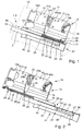
- FIGS. 1 to 4 show a preferred embodiment of the damping device 11 of the invention.
- the damping device is shown here by way of example when used for damping the opening movement of a movable furniture part 12 in the form of a drawer and described.
- the drawer by means of a guide device relative to a furniture body (not shown) slidably mounted.
- the guide device comprises a plurality of guide units (not shown), of which two guide units are assigned to mutually opposite side edges of the drawer.
- the guide units each have a carcass rail, which may be equipped, for example, as a bent sheet metal component.
- the carcass rail is fastened in a fixed position via suitable fastening means on an associated side wall of a drawer receiver formed in the furniture carcass.
- a middle rail (not shown) is displaceably mounted on which in turn a pull-out rail or rail is guided displaceably by means of bearing means.
- the drawer rail is assigned to the drawer and runs below the drawer bottom in the depth direction.
- the combination of carcase rail, center rail and pull-out rail is called full extension.
- the damping device 11 comprises a stationary base unit 13 having the furniture body of the furniture.
- the damping device 11 further comprises a drawer having the drawer movable base unit 14, wherein the movable base unit 14 is arranged to be movable relative to the stationary base unit 13.
- the stationary base unit 13 has an accessory carrier 15, which has at least one mounting interface 16 for tool-free attachment to the furniture component and at least one attachment interface for attachment of accessories to the accessory carrier 15.
- the accessory carrier 15 is formed as a flat body, for example in the form of a carrier plate.
- the accessory carrier 15 is expediently made of plastic.
- the accessory carrier 15 is a plastic injection molded part, with which it is often reproducible and can be produced in a simple and cost-effective manner.
- the mounting interface 16 is located on an upper side 18 of the accessory carrier 15.
- the mounting interface 16 has first and second holding means 19a, 19b, via which the accessory carrier 15 can be detachably fastened to a mounting section of an associated mounting bracket of the carcass rail.
- the first and second holding means 19a, 19b overlap in the assembled state of the accessory carrier 15, the mounting portion on the mounting bracket.
- the accessory carrier 15 has a transverse to the longitudinal extension slot 20 which is open to a longitudinal side of the accessory carrier 15 out.
- the slot 20 is formed by suitable demolding in the manufacture of the existing plastic material accessory carrier 15 with the same.
- the slot 20 diverges to the longitudinal side of the accessory carrier 15. In other words, the slot width of Slit 20 increases towards the longitudinal side of the accessory carrier 15 out.
- the slot 20 separates the accessory carrier 15 into a first and a second carrier part 21a, 21b.
- the two carrier parts 21a, 21b are movable relative to one another such that the distance between the two holding means 19a, 19b for mounting the accessory carrier 15 on the associated mounting portion of the mounting bracket of the carcass rail with enlargement of the slot 20 can be increased.
- the two carrier parts 21a, 21b are connected together at the bottom of the slot 20 via a solid-state joint 22.
- the spring means 23 are arranged, the spring force against the expansion of the slot 20 acts.
- the spring means 23 are integrally connected to the two support parts 21a, 21b.
- the spring means 23 comprise, in the example, two loop-shaped leaf springs 24a, 24b which are integrally formed at one end on the one and at the other end on the other support part 21a, 21b.
- the leaf springs 24 a, 24 b each have a loop portion 25 which is located in the slot width direction approximately in the center of the slot 20.
- the loop portions 25 of the leaf springs 24a, 24b face each other.
- the accessory carrier 15 has a plurality of attachment interfaces 17, one of which is on the longitudinal side of the accessory carrier 15, the longitudinal side, in addition, the slot 20 opens towards opposite, is formed.
- the attachment interface 17 on the longitudinal side of the accessory carrier 15 has a substantially in the entire length of the accessory carrier 15 extending holder in the form of a guide bar 26, on the a damper unit 27 of the damping device 11 is guided linearly movable.
- the guide rail 26 forms a sliding guide for guiding the damper unit 27 on the accessory carrier 15.
- the guide rail 26 has a guide rail 28 which forms the outer longitudinal end of the accessory carrier 15. In the direction of the center of the accessory carrier 15 is located on the top and bottom of the accessory carrier 15 each a parallel to the guide rail 28 extending guide groove 29th
- the damper unit 27 has a first damper component 30 and a second damper component 31, which are movable relative to each other.
- the first damper component is displaceably guided on the guide rail 26 of the accessory carrier 15 between a ready position 32 and a working position 33.
- the first damper component 30 has a slide-like guide element 34, which encompasses the guide rail 28 on its upper and lower sides and dips into the guide grooves 29 arranged behind it on the upper and lower sides of the accessory carrier 15.
- the carriage-like guide member 34 is, as the synopsis of FIGS. 1 to 4 shows, between the standby position 32 and the working position 33 linearly movably guided on the guide rail 26 of the accessory carrier 15.
- the first damper component 30 further has an elongated base unit 35, which is laterally attached to the carriage-like guide member 34, in particular integrally connected thereto.
- the base unit 35 is thus moved along during the movement of the guide element 34.
- the longitudinal extension the base unit 35 is significantly larger than that of the guide element 34.
- the base unit 35 has an in the longitudinal direction of the base unit 35 extending particular semi-cylindrical damper mount 36 for receiving and guiding the second damper component 31.
- the damper seat 36 has a transversely to the longitudinal extension of the damper recording aligned end stop 37, which is formed by a closure wall 38.
- the guide rail 26 has stop means 39 which define the working position 33 of the first damper component 30.
- To the stop means 39 count on the guide rail 28 at its upper and lower edges formed notches 40 which are arranged in pairs, that is, on the upper edge of the guide rail 28 has two notches, which are arranged spaced from each other in the longitudinal direction of the guide rail and of which one in the region of the front and the other is arranged in the region of the rear end of the guide rail, and which are respectively associated with the lower edge of the guide rail 28 corresponding notches 40.
- the notches 40 correspond to projections formed on the carriage-like guide member 34 (not shown).
- the first damper component 30 further comprises components of a linear damper 41, namely a damper piston assembly 42, with a piston rod 43, which is attached on the one hand to the end wall 38 of the base unit 35 and is stationary with respect to the base unit 35.
- a damper piston 44 At the other end of the piston rod 43 is a damper piston 44.
- the damper piston 44 is received in a damper housing 45, which forms the main component of the second damper component 31.
- the damper housing 45 is guided in the damper mount 36 linearly movable relative to the damper piston assembly 42 with piston rod 43 and damper piston 44.
- the movable base unit 14 has the drawer, to the drawer of which rear wall a driver element 46 projecting beyond the drawer bottom is arranged.
- the first damper component 30 with the base unit 35 and the damper piston assembly 42 becomes the standby position 32 displaced into the working position 33, which is predetermined by the rear notch pair in the displacement direction.
- damper housing 45 When the working position 33 of the first damper component 30 is reached, then the damper housing 45 is then moved relative to the damper piston assembly 42, that is, a damper function is triggered.
- the damper housing 45 moves while, as in the FIGS. 3 and 4 shown in the damper receptacle 36, wherein the damper piston 44 received in the damper piston 44 by displacement of damping medium, in particular hydraulic oil or air, generates a damping function, so that the retraction of the drawer is slowed down and damped in the open position.
- the rear of the drawer front comes into contact with the first damper component 30, whereby it is reset by the sliding guide of the carriage-like guide member 34 on the guide rail 28 from the working position 33 to the standby position 32.
- the damper housing 45 has already been reset by loss of contact with the driver element 46 in the starting position.
Landscapes
- Drawers Of Furniture (AREA)
Abstract
Description
- Die Erfindung betrifft eine Dämpfungsvorrichtung zur Dämpfung der Öffnungsbewegung eines bewegbaren Möbelteils, mit einer einen Möbelkorpus eines Möbels aufweisenden ortsfesten Basiseinheit und einer das bewegbare Möbelteil aufweisende beweglichen Basiseinheit, wobei die bewegliche Basiseinheit beweglich zur ortsfesten Basiseinheit angeordnet ist, und mit einer Dämpfereinheit, die erste und zweite, unter Ausführung einer Dämpfungsfunktion, relativ zueinander bewegliche Dämpferkomponenten aufweist, von denen die erste Dämpferkomponente an der einen Basiseinheit angeordnet ist und bei Annäherung der beweglichen Basiseinheit in seine Endlage ein Aufprall zwischen der zweiten Dämpferkomponente und der anderen Basiseinheit stattfindet, wobei die Dämpfungsfunktion auslösbar ist.
- Dämpfungsvorrichtungen zur Dämpfung der Öffnungs- und/oder Schließbewegung von bewegbaren Möbelteilen, beispielsweise Schubladen, Türen oder Klappen, sind bereits seit langem bekannt. Es ist beispielsweise bekannt, die Einfahrbewegung einer Schublade in die Schließstellung abzudämpfen. Hierbei trifft eine mit der Schublade mitbewegte Komponente auf eine Dämpferkomponente, beispielsweise ein verschiebliches Dämpfergehäuse oder einen verschieblichen Dämpferkolben und löst damit eine Dämpfungsfunktion aus. Bei der Dämpfung der Ausfahrbewegung der Schublade in die Offenstellung wird in der Regel dasselbe Prinzip verwendet.
- Die dabei eingesetzten Dämpfungsvorrichtungen besitzen stets relativ zueinander bewegliche Dämpferkomponenten, beispielsweise wie erwähnt, einen beweglichen Dämpferkolben, der beweglich in einem Dämpfergehäuse geführt ist oder ein bewegliches Dämpfergehäuse, das beweglich zu einem Dämpferkolben geführt ist. Das heißt, es wird eine bewegliche Dämpferkomponente und eine bezüglich des Möbelkorpus ortsfeste Dämpferkomponente eingesetzt.
- Angesichts beengter Platzverhältnisse ist es jedoch oftmals schwierig, geeignete Dämpfungsvorrichtungen unterzubringen. Insbesondere bei der Endlagendämpfung einer Schublade bei deren Öffnungsbewegung besteht der Bedarf, dass die Dämpfungsvorrichtung sich im Bereich der Schubladenöffnung befindet, sodass die Dämpfungsfunktion erst dann ausgelöst wird, wenn die Schublade in ihre Offenstellung einfährt. Jedoch besteht gerade hier das Problem, Dämpfungsvorrichtungen aufgrund beengter Platzverhältnisse unterzubringen.
- Aufgabe der Erfindung ist es, eine Dämpfungsvorrichtung der eingangs erwähnten Art zu schaffen, deren Einsatzgebiet gegenüber herkömmlichen Dämpfungsvorrichtungen vergrößert ist, insbesondere die auch bei beengten Platzverhältnissen funktional zuverlässig einsetzbar ist.
- Diese Aufgabe wird durch eine Dämpfungsvorrichtung mit den Merkmalen des unabhängigen Anspruchs 1 gelöst. Weiterbildungen der Erfindung sind in den Unteransprüchen dargestellt.
- Die erfindungsgemäße Dämpfungsvorrichtung zeichnet sich dadurch aus, dass die erste Dämpfungskomponente derart bewegbar an der zugeordneten Basiseinheit gelagert ist, dass sie beim Aufprall aus einer Bereitschaftsposition in eine durch Anschlagmittel abgestützte Arbeitsposition verlagerbar ist, in der die Dämpfungsfunktion ausführbar ist. Die betreffende Dämpferkomponente wird also zunächst von der Bereitschaftsposition in die Arbeitsposition verlagert, bevor die Dämpfungsfunktion ausgeführt wird. Es ist beispielsweise vorstellbar, dass die bewegliche Basiseinheit der Dämpfungsvorrichtung beim Einsatz zur Dämpfung der Öffnungsbewegung eines bewegbaren Möbelteils in Form einer Schublade zunächst die Bewegung der Schublade bis kurz vor die Offenstellung mitmacht, ohne dass eine Dämpfungsfunktion ausgelöst wird und diese dann bei Erreichen der Arbeitsposition kurz vor Erreichen der vollständig ausgefahrenen Offenstellung der Schublade ausgelöst wird. Beispielsweise kann die Dämpfereinheit der Dämpfungsvorrichtung zunächst im gesamten aus der Bereitschaftsposition in die Arbeitsposition verlagert werden, wobei dann in der Arbeitsposition die zweite Dämpferkomponente relativ beweglich zur ersten Dämpferkomponente zur Einleitung der Dämpfungsfunktion bewegt wird. Es ist beispielsweise möglich, dass die Dämpfereinheit der Dämpfungsvorrichtung zumindest teilweise aus der Schubladenaufnahme ausfährt, wodurch bei der anschließenden Dämpfung ein relativ großer Dämpfungshub verfügbar ist und die Schublade trotzdem fast komplett aus der Schubladenaufnahme ausfahrbar ist.
- Es ist möglich, dass die Dämpfereinheit der Dämpfungsvorrichtung an der ortsfesten Basiseinheit oder alternativ an der beweglichen Basiseinheit angeordnet ist. Bevorzugt ist jedoch die Anordnung der Dämpfereinheit an der ortsfesten Basiseinheit, beispielsweise an einer Korpusschiene einer Führungseinheit oder an einem Möbelkorpus eines Möbels.
- Bei einer Weiterbildung der Erfindung ist die erste Dämpferkomponente an einem an der zugeordneten Basiseinheit befestigten Halter beweglich gelagert.
- In besonders bevorzugter Weise weist der Halter die Anschlagmittel auf. In diesem Fall ist der Halter multifunktional und dient zum einen zur Führung der ersten Dämpferkomponente zwischen der Bereitschaftsposition und der Arbeitsposition und zum anderen wird durch ihn als Anschlag die Arbeitsposition definiert.
- Wie bereits erwähnt, ist es besonders bevorzugt, die erste Dämpferkomponente an der ortsfesten Basiseinheit anzuordnen. Alternativ wäre es jedoch auch möglich, die erste Dämpferkomponente an der beweglichen Basiseinheit anzuordnen. In diesem Fall würde die erste Dämpferkomponente bei der Bewegung des bewegbaren Möbelteils mitbewegt werden.
- Bei einer Weiterbildung der Erfindung weist die nicht der ersten Dämpferkomponente zugeordnete, insbesondere bewegliche Basiseinheit, ein Mitnehmerelement auf, das beim Öffnen die erste Dämpferkomponente von der Bereitschaftsposition in die Arbeitsposition verlagert. In diesem Fall kommt das Mitnehmerelement also beim Öffnen des bewegbaren Möbelteils in Kontakt mit der Dämpfereinheit und veranlasst die Bewegung der Dämpferkomponente von der Bereitschaftsposition in die Arbeitsposition.
- In besonders bevorzugter Weise löst das Mitnehmerelement die Dämpfungsfunktion aus. Es ist also möglich, dass das Mitnehmerelement in der Arbeitsposition der ersten Dämpferkomponente eine Verlagerung der ersten Dämpferkomponente relativ zur zweiten Dämpferkomponente veranlasst, wodurch eine Dämpfungsfunktion ausgelöst wird.
- Es ist möglich, dass das Mitnehmerelement auf die zweite Dämpferkomponente aufprallt und diese gemeinsam mit der ersten Dämpferkomponente verlagert, wobei letztere von der Bereitschaftsposition in die Arbeitsposition verlagert wird. Alternativ ist es jedoch auch möglich, dass das Mitnehmerelement auf die erste Dämpfungskomponente aufprallt, dies jedoch nicht eine Verlagerung der ersten Dämpferkomponente bezüglich der zweiten Dämpferkomponente und somit ein Auslösen der Dämpfungsfunktion bewirkt, sondern zunächst eine Verlagerung der gesamten Dämpfereinheit, also insbesondere der ersten Dämpferkomponente von der Bereitschaftsposition in die Arbeitsposition. Erst bei Erreichen der Arbeitsposition wird dann durch die Weiterbewegung des bewegbaren Möbelteils die erste Dämpferkomponente bezüglich der zweiten Dämpferkomponente verlagert und die Dämpfungsfunktion ausgelöst.
- Es ist also möglich, dass das Mitnehmerelement in der Arbeitsposition der ersten Dämpferkomponente zur Auslösung der Dämpfungsfunktion die zweite Dämpferkomponente gegenüber der ersten Dämpferkomponente bewegt.
- Bei einer Weiterbildung der Erfindung ist die Dämpfereinheit als Lineardämpfer mit zur Auslösung der Dämpfungsfunktion sich zueinander linear beweglichen Dämpferkomponenten oder als Rotationsdämpfer mit zur Auslösung der Dämpfungsfunktion sich zueinander rotatorisch beweglichen Dämpferkomponenten ausgebildet.
- Bei einer Weiterbildung der Erfindung sind Rückstellmittel zur Rückstellung der ersten Dämpferkomponente von der Arbeits- in die Bereitschaftsposition vorgesehen.
- Es ist möglich, dass die Rückstellmittel wenigstens ein Federelement aufweisen, deren Federkraft die erste Dämpferkomponente in die Bereitschaftsstellung zurückstellt, sobald die nicht der ersten Dämpferkomponente zugeordnete Basiseinheit außer Kontakt zur ersten Dämpferkomponente ist.
- Alternativ oder zusätzlich ist es möglich, dass die Rückstellmittel einen Funktionsabschnitt der nicht der ersten Dämpferkomponente zugeordneten Basiseinheit umfassen, der beim Schließen die erste Dämpferkomponente in die Bereitschaftsstellung verlagert.
- Die Erfindung umfasst ferner ein Möbel, mit wenigstens einem bewegbaren Möbelteil, insbesondere Schublade, gekennzeichnet durch eine Dämpfungsvorrichtung nach einem der Ansprüche 1 bis 12.
- Ein bevorzugtes Ausführungsbeispiel der Erfindung ist in der Zeichnung dargestellt und wird im Folgenden näher erläutert. In der Zeichnung zeigen:
- Figur 1
- Eine perspektivische Darstellung eines bevorzugten Ausführungsbeispiels der erfindungsgemäßen Dämpfungsvorrichtung mit der ersten Dämpferkomponente in der Bereitschaftsstellung,
- Figur 2
- eine perspektivische Darstellung der Dämpfungsvorrichtung von
Figur 1 , wobei die erste Dämpferkomponente in die Arbeitsposition verlagert ist, - Figur 3
- eine perspektivische Darstellung der Dämpfungsvorrichtungen gemäß
Figur 1 , wobei eine Dämpfungsfunktion eingeleitet ist und - Figur 4
- eine perspektivische Darstellung der Dämpfungsvorrichtung von
Figur 1 , wobei die zweite Dämpferkomponente den maximalen Dämpfungshub zurückgelegt hat. - Die
Figuren 1 bis 4 zeigen ein bevorzugtes Ausführungsbeispiel der erfindungsgemäßen Dämpfungsvorrichtung 11. Die Dämpfungsvorrichtung ist hier beispielhaft beim Einsatz zur Dämpfung der Öffnungsbewegung eines bewegbaren Möbelteils 12 in Form einer Schublade gezeigt und beschrieben. - Die Schublade ist mittels einer Führungseinrichtung (nicht dargestellt) relativ zu einem Möbelkorpus (nicht dargestellt) verschieblich gelagert. Die Führungsvorrichtung umfasst mehrere Führungseinheiten (nicht dargestellt), von denen zwei Führungseinheiten einander entgegengesetzt liegenden Seitenrändern der Schublade zugeordnet sind.
- Die Führungseinheiten besitzen jeweils eine Korpusschiene, die beispielsweise als umgebogenes Blechbauteil ausgestattet sein kann. Die Korpusschiene ist über geeignete Befestigungsmittel an einer zugeordneten Seitenwand einer im Möbelkorpus ausgebildeten Schubladenaufnahme positionsfest befestigt. An der Korpusschiene ist eine Mittelschiene (nicht dargestellt) verschieblich gelagert, an der wiederrum eine Auszugsschiene oder Laufschiene mittels Lagermitteln verschieblich geführt ist. Die Auszugsschiene ist der Schublade zugeordnet und verläuft unterhalb des Schubalden-Bodens in Tiefenrichtung. Die Kombination aus Korpusschiene, Mittelschiene und Auszugsschiene wird Vollauszug genannt. Es ist jedoch auf denkbar, Führungseinheiten ohne Mittelschiene zu verwenden.
- Die Dämpfungsvorrichtung 11 umfasst eine den Möbelkorpus des Möbels aufweisende ortsfeste Basiseinheit 13. Die Dämpfungsvorrichtung 11 umfasst ferner eine die Schublade aufweisende bewegliche Basiseinheit 14, wobei die bewegliche Basiseinheit 14 beweglich zur ortsfesten Basiseinheit 13 angeordnet ist.
- Die ortsfeste Basiseinheit 13 besitzt einen Zubehörträger 15, der wenigstens eine Montageschnittstelle 16 zur werkzeuglosen Befestigung an der Möbelkomponente und wenigstens eine Befestigungsschnittstelle zur Befestigung von Zubehörteilen am Zubehörträger 15 aufweist.
- Wie in den
Figuren 1 bis 4 gezeigt, ist der Zubehörträger 15 als Flachkörper ausgebildet, beispielsweise in Form einer Trägerplatte. Der Zubehörträger 15 besteht zweckmäßigerweise aus Kunststoff. Mit Vorteil ist der Zubehörträger 15 ein Kunststoffspritzgießteil, womit er vielfach reproduzierbar und in einfacher und kostengünstiger Weise herstellbar ist. - Im gezeigten Beispiel 2 befindet sich die Montageschnittstelle 16 an einer Oberseite 18 des Zubehörträgers 15. Die Montageschnittstelle 16 besitzt erste und zweite Haltemittel 19a, 19b, über die der Zubehörträger 15 lösbar an einem Montageabschnitt eines zugeordneten Montagewinkels der Korpusschiene befestigt werden kann.
- Die ersten und zweiten Haltemittel 19a, 19b übergreife im Montagezustand des Zubehörträgers 15 den Montageabschnitt am Montagewinkel.
- Der Zubehörträger 15 weist einen sich quer zu dessen Längserstreckung verlaufenden Schlitz 20 auf, der zu einer Längsseite des Zubehörträgers 15 hin offen ist. Der Schlitz 20 wird durch geeignete Entformung bei der Herstellung des aus Kunststoffmaterial bestehenden Zubehörträgers 15 gleich mit angeformt. Der Schlitz 20 divergiert zur Längsseite des Zubehörträgers 15. Mit anderen Worten, die Schlitzbreite des Schlitzes 20 vergrößert sich zur Längsseite des Zubehörträgers 15 hin.
- Der Schlitz 20 trennt den Zubehörträger 15 in ein erstes und zweites Trägerteil 21a, 21b. Die beiden Trägerteile 21a, 21b sind derart relativ zueinander bewegbar, dass der Abstand zwischen den beiden Haltemitteln 19a, 19b zur Montage des Zubehörträgers 15 an dem zugeordneten Montageabschnitt des Montagewinkels der Korpusschiene unter Aufweitung des Schlitzes 20 vergrößerbar ist. Die beiden Trägerteile 21a, 21b sind am Grund des Schlitzes 20 über ein Festkörpergelenk 22 miteinander verbunden.
- Im Schlitz 20 sind Federmittel 23 angeordnet, deren Federkraft gegen die Aufweitung des Schlitzes 20 wirkt. Die Federmittel 23 sind einstückig mit den beiden Trägerteilen 21a, 21b verbunden. Die Federmittel 23 umfassen im Beispielsfall zwei schlaufenförmig gestaltete Blattfedern 24a, 24b, die jeweils einenends am einen und andernends am anderen Trägerteil 21a, 21b angeformt sind. Die Blattfedern 24a, 24b besitzen jeweils einen Schlaufenabschnitt 25, der sich in Schlitz-Breitenrichtung etwa in der Mitte des Schlitzes 20 befindet. Die Schlaufenabschnitte 25 der Blattfedern 24a, 24b sind einander zugewandt.
- Wie in den
Figuren 1 bis 4 dargestellt, besitzt der Zubehörträger 15 mehrere Befestigungsschnittstellen 17, von denen eine an der Längsseite des Zubehörträgers 15, die der Längsseite, zudem sich der Schlitz 20 hin öffnet, gegenüberliegt, ausgebildet ist. Die Befestigungsschnittstelle 17 an der Längsseite des Zubehörträgers 15 besitzt einen sich im Wesentlichen über die gesamte Länge des Zubehörträgers 15 erstreckenden Halter in Form einer Führungsleiste 26, an der eine Dämpfereinheit 27 der Dämpfungsvorrichtung 11 linear beweglichen geführt ist. Die Führungsleiste 26 bildet eine Schiebeführung zur Führung der Dämpfereinheit 27 am Zubehörträger 15. Die Führungsleiste 26 besitzt eine Leitschiene 28, die den äußeren längsseitigen Abschluss des Zubehörträgers 15 bildet. In Richtung des Zentrums des Zubehörträgers 15 befindet sich an der Ober- und Unterseite des Zubehörträgers 15 jeweils eine parallel zur Leitschiene 28 verlaufende Führungsnut 29. - Wie insbesondere die Figuren zeigen, besitzt die Dämpfereinheit 27 eine erste Dämpferkomponente 30 und eine zweite Dämpferkomponente 31, die relativ zueinander beweglich sind.
- Im gezeigten Beispielsfall ist die erste Dämpferkomponente an der Führungsleiste 26 des Zubehörträgers 15 zwischen einer Bereitschaftsposition 32 und einer Arbeitsposition 33 verschieblich geführt.
- Die erste Dämpferkomponente 30 besitzt hierzu ein schlittenartiges Führungselement 34, das die Leitschiene 28 an ihrer Ober- und Unterseite umgreift und in die dahinter angeordneten Führungsnuten 29 an der Ober- und Unterseite des Zubehörträgers 15 eintaucht. Das schlittenartige Führungselement 34 ist, wie die Zusammenschau der
Figuren 1 bis 4 zeigt, zwischen der Bereitschaftsposition 32 und der Arbeitsposition 33 linear beweglich an der Führungsleiste 26 des Zubehörträgers 15 geführt. - Die erste Dämpferkomponente 30 besitzt ferner eine langgestreckte Basiseinheit 35, die seitlich an das schlittenartige Führungselement 34 angesetzt, insbesondere einstückig mit diesem verbunden ist. Die Basiseinheit 35 wird also bei der Bewegung des Führungselements 34 mitbewegt. Die Längserstreckung der Basiseinheit 35 ist deutlich größer als die des Führungselements 34.
- Die Basiseinheit 35 besitzt eine sich in Längsrichtung der Basiseinheit 35 erstreckende insbesondere halbzylindrische Dämpferaufnahme 36, zur Aufnahme und Führung der zweiten Dämpferkomponente 31. Die Dämpferaufnahme 36 besitzt einen sich quer zur Längserstreckung der Dämpferaufnahme ausgerichteten Endanschlag 37, der von einer Abschlusswand 38 gebildet wird.
- Wie insbesondere in
Figur 1 gezeigt, besitzt die Führungsleiste 26 Anschlagmittel 39, die die Arbeitsposition 33 der ersten Dämpferkomponente 30 definieren. Zu den Anschlagmitteln 39 zählen an der Leitschiene 28 an dessen Ober- und Unterkante ausgebildete Kerben 40, die insbesondere paarweise angeordnet sind, das heißt an der Oberkante der Leitschiene 28 sind zwei Kerben ausgebildet, die in Längsrichtung der Leitschiene beabstandet zueinander angeordnet sind und von denen die eine im Bereich der vorderen und die andere im Bereich des hinteren Endes der Leitschiene angeordnet ist, und denen jeweils an der Unterkante der Leitschiene 28 korrespondierende Kerben 40 zugeordnet sind. Die Kerben 40 korrespondieren mit an dem schlittenartigen Führungselement 34 ausgebildeten Vorsprüngen (nicht dargestellt). - Die erste Dämpferkomponente 30 umfasst ferner Komponenten eines Lineardämpfers 41, nämlich eine Dämpferkolbenanordnung 42, mit einer Kolbenstange 43, die einerseits an der Abschlusswand 38 der Basiseinheit 35 befestigt ist und ortsfest bezüglich der Basiseinheit 35 ausgebildet ist. Am anderen Ende der Kolbenstange 43 befindet sich ein Dämpferkolben 44. Der Dämpferkolben 44 ist in einem Dämpfergehäuse 45 aufgenommen, das den Hauptbestandteil der zweiten Dämpferkomponente 31 bildet. Das Dämpfergehäuse 45 ist in der Dämpferaufnahme 36 linear beweglich gegenüber der Dämpferkolbenanordnung 42 mit Kolbenstange 43 und Dämpferkolben 44 geführt.
- Wie insbesondere in
Figur 1 dargestellt, besitzt die bewegliche Basiseinheit 14 die Schublade, an dessen SchubladenRückwand ein über den Schubladen-Boden hinausragendes Mitnehmerelement 46 angeordnet ist. - Beim Öffnen der Schublade kommt das Mitnehmerelement 46 in Kontakt mit dem Dämpfergehäuse 45 der zweiten Dämpferkomponente 31 an der ortsfesten Basiseinheit 13. Diese Situation ist in
Figur 1 dargestellt. Beim Aufprall des Mitnehmerelements 46 auf die hintere Stirnseite des Dämpfergehäuses 45 wird die komplette Dämpfereinheit 27 und somit die in der Bereitschaftsposition 32 (Figur 1 ) befindliche erste Dämpferkomponente 30 mit der Basiseinheit 35 und der Dämpferkolbenanordnung 42 verschoben, indem das schlittenartige Führungselement 34 an der zugeordneten Leitschiene 28 der Führungsleiste 26 linear verlagert wird. Die Kraft, die zur Verlagerung der kompletten Dämpfereinheit 27 aufgewendet werden muss ist hierbei geringer, als diejenige, die zur Verschiebung des Dämpfergehäuses 45 bezüglich der Dämpferkolbenanordnung 42 benötigt wird. Daher wird beim Aufprall des Mitnehmerelements 46 auf die hintere Stirnseite des Dämpfergehäuses 45 noch keine Dämpfungsfunktion ausgelöst, sondern das Dämpfergehäuse 45 wird mitsamt der Dämpferkolbenanordnung 42 und der Basiseinheit 35 der ersten Dämpferkomponente 30 verlagert. - Die erste Dämpferkomponente 30 mit der Basiseinheit 35 und der Dämpferkolbenanordnung 42 wird von der Bereitschaftsposition 32 in die Arbeitsposition 33 verlagert, die durch das in Verlagerungsrichtung hintere Kerbenpaar vorgegeben ist.
- Charakteristisch ist, dass die Basiseinheit 35 in der Arbeitsposition 33 der ersten Dämpferkomponente 30 mit der Dämpferkolbenanordnung 42 aus der Schubladenaufnahme herausgefahren ist. Eine Dämpfungsfunktion hat also bisher nicht stattgefunden und die Schublade kann fast bis ganz zur Offenstellung gefahren werden, bis die Dämpfungsfunktion einsetzt.
- Ist die Arbeitsposition 33 der ersten Dämpferkomponente 30 erreicht, so wird anschließend das Dämpfergehäuse 45 relativ zur Dämpferkolbenanordnung 42 bewegt, das heißt, eine Dämpferfunktion wird ausgelöst. Das Dämpfergehäuse 45 fährt dabei, wie in den
Figuren 3 und 4 dargestellt, in die Dämpferaufnahme 36 ein, wobei der im Dämpfergehäuse 45 aufgenommene Dämpferkolben 44 durch Verdrängung von Dämpfungsmedium, insbesondere Hydrauliköl oder Luft, eine Dämpfungsfunktion erzeugt, sodass das Einfahren der Schublade in die Offenstellung abgebremst und gedämpft wird. - Beim Einfahren der Schublade kommt die Rückseite der Schubladen-Front mit der ersten Dämpferkomponente 30 in Kontakt, wodurch diese durch die Schiebeführung des schlittenartigen Führungselements 34 an der Leitschiene 28 von der Arbeitsposition 33 in die Bereitschaftsposition 32 rückgestellt wird. Zuvor wurde bereits das Dämpfergehäuse 45 durch Kontaktverlust mit dem Mitnehmerelement 46 in die Ausgangsstellung rückgestellt.
Claims (13)
- Dämpfungsvorrichtung zur Dämpfung der Öffnungsbewegung eines bewegbaren Möbelteils (12), mit einer einen Möbelkorpus eines Möbels aufweisenden ortsfesten Basiseinheit (13) und einer das bewegbare Möbelteil aufweisenden beweglichen Basiseinheit (14), wobei die bewegliche Basiseinheit (14) beweglich zur ortsfesten Basiseinheit (13) angeordnet ist, und mit einer Dämpfereinheit (27), die erste und zweite, unter Ausführung einer Dämpfungsfunktion, relativ zueinander bewegliche Dämpferkomponenten (30, 31) aufweist, von denen die erste Dämpferkomponente (30) an der einen Basiseinheit (13, 14) angeordnet ist und bei Annäherung der beweglichen Basiseinheit (14) in seine Endlage ein Aufprall zwischen der zweiten Dämpferkomponente (31) und der anderen Basiseinheit (13, 14) stattfindet, wobei die Dämpfungsfunktion auslösbar ist, dadurch gekennzeichnet, dass die erste Dämpferkomponente (30) derart bewegbar an der zugeordneten Basiseinheit (13, 14) gelagert ist, dass sie beim Aufprall aus einer Bereitschaftposition (32) in eine durch Anschlagmittel (39) abgestützte Arbeitsposition (33) verlagerbar ist, in der die Dämpfungsfunktion ausführbar ist.
- Dämpfungsvorrichtung nach Anspruch 1, dadurch gekennzeichnet, dass die erste Dämpferkomponente (30) an einem an der zugeordneten Basiseinheit (13, 14) befestigten Halter beweglich gelagert ist.
- Dämpfungsvorrichtung nach Anspruch 2, dadurch gekennzeichnet, dass der Halter die Anschlagmittel (39) aufweist.
- Dämpfungsvorrichtung nach einem der vorhergehenden Ansprüche, dadurch gekennzeichnet, dass die erste Dämpferkomponente (30) an der ortsfesten Basiseinheit (13) angeordnet ist.
- Dämpfungsvorrichtung nach einem der vorhergehenden Ansprüche, dadurch gekennzeichnet, dass die nicht der ersten Dämpferkomponente (30) zugeordnete, insbesondere bewegliche Basiseinheit (14), ein Mitnehmerelement (46) aufweist, das beim Öffnen die erste Dämpferkomponente (30) von der Bereitschaftsposition (32) in die Arbeitsposition (33) verlagert.
- Dämpfungsvorrichtung nach Anspruch 5, dadurch gekennzeichnet, dass das Mitnehmerelement (46) die Dämpfungsfunktion auslöst.
- Dämpfungsvorrichtung nach Anspruch 5 oder 6, dadurch gekennzeichnet, dass das Mitnehmerelement (46) auf die zweite Dämpferkomponente (31) aufprallt und diese gemeinsam mit der ersten Dämpferkomponente (30) verlagert, wobei letztere von der Bereitschaftsposition (32) in die Arbeitsposition (33) verlagert wird.
- Dämpfungsvorrichtung nach Anspruch 7, dadurch gekennzeichnet, dass das Mitnehmerelement (46) in der Arbeitsposition (33) der ersten Dämpferkomponente (30) die zweite Dämpferkomponente (31) gegenüber der ersten Dämpferkomponente (30) bewegt.
- Dämpfungsvorrichtung nach einem der vorhergehenden Ansprüche, dadurch gekennzeichnet, dass die Dämpfereinheit (27) als Lineardämpfer mit zur Auslösung der Dämpfungsfunktion sich zueinander linear beweglichen Dämpferkomponenten oder als Rotationsdämpfer mit zur Auslösung der Dämpfungsfunktion sich zueinander rotatorisch beweglichen Dämpferkomponenten ausgebildet ist.
- Dämpfungsvorrichtung nach einem der vorhergehenden Ansprüche, gekennzeichnet durch Rückstellmittel zur Rückstellung der ersten Dämpferkomponente (30) von der Arbeits- in die Bereitschaftsposition (33, 32).
- Dämpfungsvorrichtung nach Anspruch 10, dadurch gekennzeichnet, dass die Rückstellmittel wenigstens ein Federelement aufweisen, deren Federkraft die erste Dämpferkomponente (30) in die Bereitschaftsposition (32) zurückstellt, sobald die nicht der ersten Dämpferkomponente (30) zugeordnete Basiseinheit (13, 14) außer Kontakt zur ersten Dämpferkomponente (30) ist.
- Dämpfungsvorrichtung nach Anspruch 10 oder 11, dadurch gekennzeichnet, dass die Rückstellmittel einen Funktionsabschnitt, der nicht der ersten Dämpferkomponente (30) zugeordneten Basiseinheit (13) umfassen, der beim Schließen die ersten Dämpferkomponente (30) in die Bereitschaftsposition (32) verlagert.
- Möbel, mit wenigstens einem bewegbaren Möbelteil, insbesondere Schublade, gekennzeichnet durch eine Dämpfungsvorrichtung (11) nach einem der Ansprüche 1 bis 12.
Applications Claiming Priority (1)
| Application Number | Priority Date | Filing Date | Title |
|---|---|---|---|
| DE202015006279.2U DE202015006279U1 (de) | 2015-09-04 | 2015-09-04 | Dämpfungsvorrichtung zur Dämpfung der Öffnungsbewegung eines bewegbaren Möbelteils |
Publications (2)
| Publication Number | Publication Date |
|---|---|
| EP3138441A1 true EP3138441A1 (de) | 2017-03-08 |
| EP3138441B1 EP3138441B1 (de) | 2019-10-02 |
Family
ID=56683837
Family Applications (1)
| Application Number | Title | Priority Date | Filing Date |
|---|---|---|---|
| EP16184015.2A Active EP3138441B1 (de) | 2015-09-04 | 2016-08-12 | Dämpfungsvorrichtung zur dämpfung der öffnungsbewegung eines bewegbaren möbelteils |
Country Status (4)
| Country | Link |
|---|---|
| US (1) | US9885205B2 (de) |
| EP (1) | EP3138441B1 (de) |
| CN (1) | CN106617811B (de) |
| DE (1) | DE202015006279U1 (de) |
Families Citing this family (6)
| Publication number | Priority date | Publication date | Assignee | Title |
|---|---|---|---|---|
| EP3112570A4 (de) * | 2014-02-28 | 2017-11-29 | Sugatsune Kogyo CO., LTD. | Schliesssatz für schiebetür |
| DE202015006278U1 (de) * | 2015-09-04 | 2016-12-06 | Grass Gmbh | Führungsvorrichtung zur Führung eines relativ zu einem Möbelkorpus bewegbaren Möbelauszugs |
| TWI665983B (zh) | 2017-04-12 | 2019-07-21 | 川湖科技股份有限公司 | 滑軌總成 |
| CN108720380B (zh) * | 2017-04-19 | 2019-09-06 | 川湖科技股份有限公司 | 滑轨总成 |
| CN108720382B (zh) * | 2017-04-19 | 2019-10-25 | 川湖科技股份有限公司 | 滑轨总成 |
| TWI703917B (zh) * | 2019-12-23 | 2020-09-01 | 川湖科技股份有限公司 | 機架系統及其滑軌機構 |
Citations (3)
| Publication number | Priority date | Publication date | Assignee | Title |
|---|---|---|---|---|
| DE202004006410U1 (de) * | 2004-04-20 | 2005-09-01 | Alfit Ag | Einzugsautomatik mit Dämpfungsvorrichtung für Schubladen-Ausziehführungen |
| EP1625810A1 (de) * | 2004-08-10 | 2006-02-15 | Schock Metallwerk GmbH | Bewegungsdämpfungsvorrichtung |
| DE102012111551A1 (de) * | 2011-11-28 | 2013-05-29 | Paul Hettich Gmbh & Co. Kg | Auszugsführung |
Family Cites Families (8)
| Publication number | Priority date | Publication date | Assignee | Title |
|---|---|---|---|---|
| DE202007001897U1 (de) * | 2006-05-24 | 2007-09-27 | Paul Hettich Gmbh & Co. Kg | Schließ- und Haltevorrichtung für eine Ausziehführung |
| DK200700695A (da) * | 2007-05-09 | 2008-11-10 | Inter Ikea Sys Bv | Indretning til sikring af en blöd afslutning af en skuffes åbningsbevægelse |
| DE102010036741B4 (de) * | 2009-08-07 | 2020-10-08 | Paul Hettich Gmbh & Co. Kg | Auszugssystem |
| MY155806A (en) * | 2010-07-29 | 2015-11-30 | Harn Marketing Sdn Bhd | Drawer guide rail system |
| GB2496864B (en) * | 2011-11-22 | 2016-08-31 | Titus Int Ltd | Improvements in damper assemblies |
| AT512512B1 (de) * | 2012-07-10 | 2013-09-15 | Blum Gmbh Julius | Antriebsvorrichtung für ein bewegbares Möbelteil |
| DE202013011559U1 (de) * | 2013-12-23 | 2015-03-24 | Grass Gmbh | Dämpfungsvorrichtung |
| US8939525B1 (en) * | 2014-01-27 | 2015-01-27 | Martas Precision Slide Co., Ltd. | Self-closing buffer and automatic rebound mechanism for slide rail |
-
2015
- 2015-09-04 DE DE202015006279.2U patent/DE202015006279U1/de not_active Expired - Lifetime
-
2016
- 2016-08-12 EP EP16184015.2A patent/EP3138441B1/de active Active
- 2016-09-02 US US15/255,883 patent/US9885205B2/en active Active
- 2016-09-05 CN CN201610801695.2A patent/CN106617811B/zh active Active
Patent Citations (3)
| Publication number | Priority date | Publication date | Assignee | Title |
|---|---|---|---|---|
| DE202004006410U1 (de) * | 2004-04-20 | 2005-09-01 | Alfit Ag | Einzugsautomatik mit Dämpfungsvorrichtung für Schubladen-Ausziehführungen |
| EP1625810A1 (de) * | 2004-08-10 | 2006-02-15 | Schock Metallwerk GmbH | Bewegungsdämpfungsvorrichtung |
| DE102012111551A1 (de) * | 2011-11-28 | 2013-05-29 | Paul Hettich Gmbh & Co. Kg | Auszugsführung |
Also Published As
| Publication number | Publication date |
|---|---|
| US9885205B2 (en) | 2018-02-06 |
| DE202015006279U1 (de) | 2016-12-07 |
| CN106617811B (zh) | 2019-02-12 |
| EP3138441B1 (de) | 2019-10-02 |
| CN106617811A (zh) | 2017-05-10 |
| US20170067277A1 (en) | 2017-03-09 |
Similar Documents
| Publication | Publication Date | Title |
|---|---|---|
| EP3138441B1 (de) | Dämpfungsvorrichtung zur dämpfung der öffnungsbewegung eines bewegbaren möbelteils | |
| AT518136B1 (de) | Schubladenausziehführung | |
| DE102013101358B4 (de) | Auszugsführung für ein bewegbares Möbelteil | |
| EP3183997B1 (de) | Führungseinrichtung zur führung eines relativ zu einem möbelkorpus bewegbaren möbelteils | |
| AT519593A1 (de) | Verriegelungsvorrichtung | |
| EP3439505A2 (de) | Möbelantrieb | |
| EP1907657A1 (de) | Dämpfungselement | |
| EP3142516B1 (de) | Einzugsvorrichtung für möbel | |
| EP2534326B1 (de) | Einzugvorrichtung für schiebetüren | |
| EP3138442B1 (de) | Führungsvorrichtung zur führung eines relativ zu einem möbelkorpus bewegbaren möbelauszugs | |
| DE202004006410U1 (de) | Einzugsautomatik mit Dämpfungsvorrichtung für Schubladen-Ausziehführungen | |
| DE29616054U1 (de) | Möbelauszug mit Selbsteinzug | |
| EP2694765B1 (de) | Einzugvorrichtung | |
| EP3062661B1 (de) | Vorrichtung zum öffnen eines bewegbaren möbelteils | |
| EP2739807B1 (de) | Beschlagsystem zum führen einer verschlussklappe eines möbelstücks | |
| EP2848759B1 (de) | Dämpfungsvorrichtung | |
| EP1817984B1 (de) | Vorrichtung zur Beeinflussung der Bewegung von relativ zueinander bewegbaren Möbelteilen, insbesondere für Schubladenführungen sowie Schubladenführung mit einer solchen Vorrichtung | |
| EP3138443B1 (de) | Vorrichtung zur befestigung von zubehörteilen an einer möbelkomponente eines möbels | |
| DE202018105183U1 (de) | Kollisionsdämpfer für Möbelteile | |
| EP4473870A1 (de) | Vorrichtung zum öffnen und schliessen eines bewegbaren möbelteils | |
| EP3532690B1 (de) | Dämpfungseinheit für ein schiebeelement | |
| DE202010000143U1 (de) | Einzugvorrichtung für Schiebetüren | |
| DE202014105643U1 (de) | Ausziehführung für Schubkästen | |
| AT10534U1 (de) | Vorrichtung zur dämpfung eines stossvorganges beim zusammentreffen von zueinander bewegbaren möbelteilen eines möbels |
Legal Events
| Date | Code | Title | Description |
|---|---|---|---|
| PUAI | Public reference made under article 153(3) epc to a published international application that has entered the european phase |
Free format text: ORIGINAL CODE: 0009012 |
|
| STAA | Information on the status of an ep patent application or granted ep patent |
Free format text: STATUS: THE APPLICATION HAS BEEN PUBLISHED |
|
| AK | Designated contracting states |
Kind code of ref document: A1 Designated state(s): AL AT BE BG CH CY CZ DE DK EE ES FI FR GB GR HR HU IE IS IT LI LT LU LV MC MK MT NL NO PL PT RO RS SE SI SK SM TR |
|
| AX | Request for extension of the european patent |
Extension state: BA ME |
|
| STAA | Information on the status of an ep patent application or granted ep patent |
Free format text: STATUS: REQUEST FOR EXAMINATION WAS MADE |
|
| 17P | Request for examination filed |
Effective date: 20170906 |
|
| RBV | Designated contracting states (corrected) |
Designated state(s): AL AT BE BG CH CY CZ DE DK EE ES FI FR GB GR HR HU IE IS IT LI LT LU LV MC MK MT NL NO PL PT RO RS SE SI SK SM TR |
|
| STAA | Information on the status of an ep patent application or granted ep patent |
Free format text: STATUS: EXAMINATION IS IN PROGRESS |
|
| 17Q | First examination report despatched |
Effective date: 20180709 |
|
| REG | Reference to a national code |
Ref country code: DE Ref legal event code: R079 Ref document number: 502016006871 Country of ref document: DE Free format text: PREVIOUS MAIN CLASS: A47B0088400000 Ipc: E05F0005000000 |
|
| RIC1 | Information provided on ipc code assigned before grant |
Ipc: A47B 88/40 20170101ALI20190425BHEP Ipc: E05F 5/00 20170101AFI20190425BHEP Ipc: E05F 5/02 20060101ALN20190425BHEP |
|
| GRAP | Despatch of communication of intention to grant a patent |
Free format text: ORIGINAL CODE: EPIDOSNIGR1 |
|
| STAA | Information on the status of an ep patent application or granted ep patent |
Free format text: STATUS: GRANT OF PATENT IS INTENDED |
|
| RIC1 | Information provided on ipc code assigned before grant |
Ipc: E05F 5/00 20170101AFI20190513BHEP Ipc: E05F 5/02 20060101ALN20190513BHEP Ipc: A47B 88/40 20170101ALI20190513BHEP |
|
| INTG | Intention to grant announced |
Effective date: 20190607 |
|
| GRAS | Grant fee paid |
Free format text: ORIGINAL CODE: EPIDOSNIGR3 |
|
| GRAA | (expected) grant |
Free format text: ORIGINAL CODE: 0009210 |
|
| STAA | Information on the status of an ep patent application or granted ep patent |
Free format text: STATUS: THE PATENT HAS BEEN GRANTED |
|
| AK | Designated contracting states |
Kind code of ref document: B1 Designated state(s): AL AT BE BG CH CY CZ DE DK EE ES FI FR GB GR HR HU IE IS IT LI LT LU LV MC MK MT NL NO PL PT RO RS SE SI SK SM TR |
|
| REG | Reference to a national code |
Ref country code: GB Ref legal event code: FG4D Free format text: NOT ENGLISH |
|
| REG | Reference to a national code |
Ref country code: CH Ref legal event code: EP Ref country code: AT Ref legal event code: REF Ref document number: 1186351 Country of ref document: AT Kind code of ref document: T Effective date: 20191015 |
|
| REG | Reference to a national code |
Ref country code: DE Ref legal event code: R096 Ref document number: 502016006871 Country of ref document: DE |
|
| REG | Reference to a national code |
Ref country code: IE Ref legal event code: FG4D Free format text: LANGUAGE OF EP DOCUMENT: GERMAN |
|
| REG | Reference to a national code |
Ref country code: NL Ref legal event code: MP Effective date: 20191002 |
|
| REG | Reference to a national code |
Ref country code: LT Ref legal event code: MG4D |
|
| PG25 | Lapsed in a contracting state [announced via postgrant information from national office to epo] |
Ref country code: PT Free format text: LAPSE BECAUSE OF FAILURE TO SUBMIT A TRANSLATION OF THE DESCRIPTION OR TO PAY THE FEE WITHIN THE PRESCRIBED TIME-LIMIT Effective date: 20200203 Ref country code: GR Free format text: LAPSE BECAUSE OF FAILURE TO SUBMIT A TRANSLATION OF THE DESCRIPTION OR TO PAY THE FEE WITHIN THE PRESCRIBED TIME-LIMIT Effective date: 20200103 Ref country code: BG Free format text: LAPSE BECAUSE OF FAILURE TO SUBMIT A TRANSLATION OF THE DESCRIPTION OR TO PAY THE FEE WITHIN THE PRESCRIBED TIME-LIMIT Effective date: 20200102 Ref country code: FI Free format text: LAPSE BECAUSE OF FAILURE TO SUBMIT A TRANSLATION OF THE DESCRIPTION OR TO PAY THE FEE WITHIN THE PRESCRIBED TIME-LIMIT Effective date: 20191002 Ref country code: NO Free format text: LAPSE BECAUSE OF FAILURE TO SUBMIT A TRANSLATION OF THE DESCRIPTION OR TO PAY THE FEE WITHIN THE PRESCRIBED TIME-LIMIT Effective date: 20200102 Ref country code: SE Free format text: LAPSE BECAUSE OF FAILURE TO SUBMIT A TRANSLATION OF THE DESCRIPTION OR TO PAY THE FEE WITHIN THE PRESCRIBED TIME-LIMIT Effective date: 20191002 Ref country code: LV Free format text: LAPSE BECAUSE OF FAILURE TO SUBMIT A TRANSLATION OF THE DESCRIPTION OR TO PAY THE FEE WITHIN THE PRESCRIBED TIME-LIMIT Effective date: 20191002 Ref country code: NL Free format text: LAPSE BECAUSE OF FAILURE TO SUBMIT A TRANSLATION OF THE DESCRIPTION OR TO PAY THE FEE WITHIN THE PRESCRIBED TIME-LIMIT Effective date: 20191002 Ref country code: LT Free format text: LAPSE BECAUSE OF FAILURE TO SUBMIT A TRANSLATION OF THE DESCRIPTION OR TO PAY THE FEE WITHIN THE PRESCRIBED TIME-LIMIT Effective date: 20191002 Ref country code: PL Free format text: LAPSE BECAUSE OF FAILURE TO SUBMIT A TRANSLATION OF THE DESCRIPTION OR TO PAY THE FEE WITHIN THE PRESCRIBED TIME-LIMIT Effective date: 20191002 Ref country code: ES Free format text: LAPSE BECAUSE OF FAILURE TO SUBMIT A TRANSLATION OF THE DESCRIPTION OR TO PAY THE FEE WITHIN THE PRESCRIBED TIME-LIMIT Effective date: 20191002 |
|
| PG25 | Lapsed in a contracting state [announced via postgrant information from national office to epo] |
Ref country code: IS Free format text: LAPSE BECAUSE OF FAILURE TO SUBMIT A TRANSLATION OF THE DESCRIPTION OR TO PAY THE FEE WITHIN THE PRESCRIBED TIME-LIMIT Effective date: 20200224 Ref country code: CZ Free format text: LAPSE BECAUSE OF FAILURE TO SUBMIT A TRANSLATION OF THE DESCRIPTION OR TO PAY THE FEE WITHIN THE PRESCRIBED TIME-LIMIT Effective date: 20191002 Ref country code: RS Free format text: LAPSE BECAUSE OF FAILURE TO SUBMIT A TRANSLATION OF THE DESCRIPTION OR TO PAY THE FEE WITHIN THE PRESCRIBED TIME-LIMIT Effective date: 20191002 Ref country code: HR Free format text: LAPSE BECAUSE OF FAILURE TO SUBMIT A TRANSLATION OF THE DESCRIPTION OR TO PAY THE FEE WITHIN THE PRESCRIBED TIME-LIMIT Effective date: 20191002 |
|
| PG25 | Lapsed in a contracting state [announced via postgrant information from national office to epo] |
Ref country code: AL Free format text: LAPSE BECAUSE OF FAILURE TO SUBMIT A TRANSLATION OF THE DESCRIPTION OR TO PAY THE FEE WITHIN THE PRESCRIBED TIME-LIMIT Effective date: 20191002 |
|
| REG | Reference to a national code |
Ref country code: DE Ref legal event code: R097 Ref document number: 502016006871 Country of ref document: DE |
|
| PG2D | Information on lapse in contracting state deleted |
Ref country code: IS |
|
| PG25 | Lapsed in a contracting state [announced via postgrant information from national office to epo] |
Ref country code: DK Free format text: LAPSE BECAUSE OF FAILURE TO SUBMIT A TRANSLATION OF THE DESCRIPTION OR TO PAY THE FEE WITHIN THE PRESCRIBED TIME-LIMIT Effective date: 20191002 Ref country code: EE Free format text: LAPSE BECAUSE OF FAILURE TO SUBMIT A TRANSLATION OF THE DESCRIPTION OR TO PAY THE FEE WITHIN THE PRESCRIBED TIME-LIMIT Effective date: 20191002 Ref country code: RO Free format text: LAPSE BECAUSE OF FAILURE TO SUBMIT A TRANSLATION OF THE DESCRIPTION OR TO PAY THE FEE WITHIN THE PRESCRIBED TIME-LIMIT Effective date: 20191002 Ref country code: IS Free format text: LAPSE BECAUSE OF FAILURE TO SUBMIT A TRANSLATION OF THE DESCRIPTION OR TO PAY THE FEE WITHIN THE PRESCRIBED TIME-LIMIT Effective date: 20200202 |
|
| PLBE | No opposition filed within time limit |
Free format text: ORIGINAL CODE: 0009261 |
|
| STAA | Information on the status of an ep patent application or granted ep patent |
Free format text: STATUS: NO OPPOSITION FILED WITHIN TIME LIMIT |
|
| PG25 | Lapsed in a contracting state [announced via postgrant information from national office to epo] |
Ref country code: SM Free format text: LAPSE BECAUSE OF FAILURE TO SUBMIT A TRANSLATION OF THE DESCRIPTION OR TO PAY THE FEE WITHIN THE PRESCRIBED TIME-LIMIT Effective date: 20191002 Ref country code: SK Free format text: LAPSE BECAUSE OF FAILURE TO SUBMIT A TRANSLATION OF THE DESCRIPTION OR TO PAY THE FEE WITHIN THE PRESCRIBED TIME-LIMIT Effective date: 20191002 |
|
| 26N | No opposition filed |
Effective date: 20200703 |
|
| PG25 | Lapsed in a contracting state [announced via postgrant information from national office to epo] |
Ref country code: SI Free format text: LAPSE BECAUSE OF FAILURE TO SUBMIT A TRANSLATION OF THE DESCRIPTION OR TO PAY THE FEE WITHIN THE PRESCRIBED TIME-LIMIT Effective date: 20191002 |
|
| PG25 | Lapsed in a contracting state [announced via postgrant information from national office to epo] |
Ref country code: MC Free format text: LAPSE BECAUSE OF FAILURE TO SUBMIT A TRANSLATION OF THE DESCRIPTION OR TO PAY THE FEE WITHIN THE PRESCRIBED TIME-LIMIT Effective date: 20191002 |
|
| REG | Reference to a national code |
Ref country code: CH Ref legal event code: PL |
|
| GBPC | Gb: european patent ceased through non-payment of renewal fee |
Effective date: 20200812 |
|
| PG25 | Lapsed in a contracting state [announced via postgrant information from national office to epo] |
Ref country code: LU Free format text: LAPSE BECAUSE OF NON-PAYMENT OF DUE FEES Effective date: 20200812 Ref country code: LI Free format text: LAPSE BECAUSE OF NON-PAYMENT OF DUE FEES Effective date: 20200831 Ref country code: CH Free format text: LAPSE BECAUSE OF NON-PAYMENT OF DUE FEES Effective date: 20200831 |
|
| REG | Reference to a national code |
Ref country code: BE Ref legal event code: MM Effective date: 20200831 |
|
| PG25 | Lapsed in a contracting state [announced via postgrant information from national office to epo] |
Ref country code: FR Free format text: LAPSE BECAUSE OF NON-PAYMENT OF DUE FEES Effective date: 20200831 |
|
| PG25 | Lapsed in a contracting state [announced via postgrant information from national office to epo] |
Ref country code: BE Free format text: LAPSE BECAUSE OF NON-PAYMENT OF DUE FEES Effective date: 20200831 Ref country code: GB Free format text: LAPSE BECAUSE OF NON-PAYMENT OF DUE FEES Effective date: 20200812 Ref country code: IE Free format text: LAPSE BECAUSE OF NON-PAYMENT OF DUE FEES Effective date: 20200812 |
|
| PG25 | Lapsed in a contracting state [announced via postgrant information from national office to epo] |
Ref country code: TR Free format text: LAPSE BECAUSE OF FAILURE TO SUBMIT A TRANSLATION OF THE DESCRIPTION OR TO PAY THE FEE WITHIN THE PRESCRIBED TIME-LIMIT Effective date: 20191002 Ref country code: MT Free format text: LAPSE BECAUSE OF FAILURE TO SUBMIT A TRANSLATION OF THE DESCRIPTION OR TO PAY THE FEE WITHIN THE PRESCRIBED TIME-LIMIT Effective date: 20191002 Ref country code: CY Free format text: LAPSE BECAUSE OF FAILURE TO SUBMIT A TRANSLATION OF THE DESCRIPTION OR TO PAY THE FEE WITHIN THE PRESCRIBED TIME-LIMIT Effective date: 20191002 |
|
| PG25 | Lapsed in a contracting state [announced via postgrant information from national office to epo] |
Ref country code: MK Free format text: LAPSE BECAUSE OF FAILURE TO SUBMIT A TRANSLATION OF THE DESCRIPTION OR TO PAY THE FEE WITHIN THE PRESCRIBED TIME-LIMIT Effective date: 20191002 |
|
| P01 | Opt-out of the competence of the unified patent court (upc) registered |
Effective date: 20230519 |
|
| PGFP | Annual fee paid to national office [announced via postgrant information from national office to epo] |
Ref country code: DE Payment date: 20250820 Year of fee payment: 10 |
|
| PGFP | Annual fee paid to national office [announced via postgrant information from national office to epo] |
Ref country code: IT Payment date: 20250808 Year of fee payment: 10 |
|
| PGFP | Annual fee paid to national office [announced via postgrant information from national office to epo] |
Ref country code: AT Payment date: 20250821 Year of fee payment: 10 |