EP3136587A2 - Vibrationsmotorsteuerung und linsenvorrichtung und bildaufnahmevorrichtung damit - Google Patents
Vibrationsmotorsteuerung und linsenvorrichtung und bildaufnahmevorrichtung damit Download PDFInfo
- Publication number
- EP3136587A2 EP3136587A2 EP16001794.3A EP16001794A EP3136587A2 EP 3136587 A2 EP3136587 A2 EP 3136587A2 EP 16001794 A EP16001794 A EP 16001794A EP 3136587 A2 EP3136587 A2 EP 3136587A2
- Authority
- EP
- European Patent Office
- Prior art keywords
- frequency
- phase difference
- velocity
- vibration motor
- relationship
- Prior art date
- Legal status (The legal status is an assumption and is not a legal conclusion. Google has not performed a legal analysis and makes no representation as to the accuracy of the status listed.)
- Withdrawn
Links
- 230000003287 optical effect Effects 0.000 claims description 10
- 230000004913 activation Effects 0.000 description 18
- 230000008859 change Effects 0.000 description 14
- 238000000034 method Methods 0.000 description 10
- 230000002411 adverse Effects 0.000 description 5
- 230000000694 effects Effects 0.000 description 5
- 230000006870 function Effects 0.000 description 5
- 230000007423 decrease Effects 0.000 description 4
- 230000001747 exhibiting effect Effects 0.000 description 3
- 239000002184 metal Substances 0.000 description 2
- 230000004044 response Effects 0.000 description 2
- 239000007787 solid Substances 0.000 description 2
- 230000001133 acceleration Effects 0.000 description 1
- 238000005352 clarification Methods 0.000 description 1
- 238000001514 detection method Methods 0.000 description 1
- 230000004048 modification Effects 0.000 description 1
- 238000012986 modification Methods 0.000 description 1
- 230000009467 reduction Effects 0.000 description 1
- 230000007704 transition Effects 0.000 description 1
Images


Classifications
-
- G—PHYSICS
- G03—PHOTOGRAPHY; CINEMATOGRAPHY; ANALOGOUS TECHNIQUES USING WAVES OTHER THAN OPTICAL WAVES; ELECTROGRAPHY; HOLOGRAPHY
- G03B—APPARATUS OR ARRANGEMENTS FOR TAKING PHOTOGRAPHS OR FOR PROJECTING OR VIEWING THEM; APPARATUS OR ARRANGEMENTS EMPLOYING ANALOGOUS TECHNIQUES USING WAVES OTHER THAN OPTICAL WAVES; ACCESSORIES THEREFOR
- G03B13/00—Viewfinders; Focusing aids for cameras; Means for focusing for cameras; Autofocus systems for cameras
- G03B13/32—Means for focusing
- G03B13/34—Power focusing
-
- H—ELECTRICITY
- H02—GENERATION; CONVERSION OR DISTRIBUTION OF ELECTRIC POWER
- H02P—CONTROL OR REGULATION OF ELECTRIC MOTORS, ELECTRIC GENERATORS OR DYNAMO-ELECTRIC CONVERTERS; CONTROLLING TRANSFORMERS, REACTORS OR CHOKE COILS
- H02P25/00—Arrangements or methods for the control of AC motors characterised by the kind of AC motor or by structural details
- H02P25/02—Arrangements or methods for the control of AC motors characterised by the kind of AC motor or by structural details characterised by the kind of motor
- H02P25/032—Reciprocating, oscillating or vibrating motors
-
- G—PHYSICS
- G02—OPTICS
- G02B—OPTICAL ELEMENTS, SYSTEMS OR APPARATUS
- G02B7/00—Mountings, adjusting means, or light-tight connections, for optical elements
- G02B7/02—Mountings, adjusting means, or light-tight connections, for optical elements for lenses
- G02B7/04—Mountings, adjusting means, or light-tight connections, for optical elements for lenses with mechanism for focusing or varying magnification
-
- H—ELECTRICITY
- H02—GENERATION; CONVERSION OR DISTRIBUTION OF ELECTRIC POWER
- H02N—ELECTRIC MACHINES NOT OTHERWISE PROVIDED FOR
- H02N2/00—Electric machines in general using piezoelectric effect, electrostriction or magnetostriction
- H02N2/0005—Electric machines in general using piezoelectric effect, electrostriction or magnetostriction producing non-specific motion; Details common to machines covered by H02N2/02 - H02N2/16
- H02N2/0075—Electrical details, e.g. drive or control circuits or methods
- H02N2/008—Means for controlling vibration frequency or phase, e.g. for resonance tracking
-
- H—ELECTRICITY
- H04—ELECTRIC COMMUNICATION TECHNIQUE
- H04N—PICTORIAL COMMUNICATION, e.g. TELEVISION
- H04N23/00—Cameras or camera modules comprising electronic image sensors; Control thereof
- H04N23/60—Control of cameras or camera modules
-
- G—PHYSICS
- G02—OPTICS
- G02B—OPTICAL ELEMENTS, SYSTEMS OR APPARATUS
- G02B7/00—Mountings, adjusting means, or light-tight connections, for optical elements
- G02B7/02—Mountings, adjusting means, or light-tight connections, for optical elements for lenses
- G02B7/04—Mountings, adjusting means, or light-tight connections, for optical elements for lenses with mechanism for focusing or varying magnification
- G02B7/08—Mountings, adjusting means, or light-tight connections, for optical elements for lenses with mechanism for focusing or varying magnification adapted to co-operate with a remote control mechanism
Definitions
- the present invention relates to a vibration motor controller, and a lens apparatus and an image pickup apparatus that include the vibration motor controller.
- the technique disclosed in Japanese Application Laid-Open No. 2011-067035 is a technique that enables use of a wide dynamic range of the driving velocity of the vibration motor.
- the frequency at phase difference control may be set to a lower frequency. In this case, however, the controllability at a low velocity region tends to be lowered.
- An object of the present invention is to provide a vibration motor controller that can achieve both of controllability and stability with a small phase difference while maintaining a wide dynamic range of the driving velocity.
- the vibration motor controller of the present invention controls driving velocity of a vibration motor that relatively moves a vibrator and a contactor in contact with the vibrator, the vibrator oscillated by an electromechanical energy transducer to which a first frequency signal and a second frequency signal having a phase difference are applied.
- the vibration motor controller includes a phase difference determiner that stores a relationship between frequency and phase difference between the first and second frequency signals, and determines the phase difference with respect to the frequency based on the relationship, and a controller that controls velocity of the vibration motor based on the frequency of the first and second frequency signals and the phase difference determined by the phase difference determiner based on the frequency.
- the relationship between the frequency and the phase difference stored in the phase difference determiner does not include a relationship between a frequency lower than a resonance frequency in frequency-velocity characteristics of the vibration motor, and the phase difference.
- both of controllability and stability with a small phase difference can be achieved while maintaining a wide dynamic range of the driving velocity.
- a vibration motor includes a vibrator formed of a metal elastic body or the like to which an electromechanical energy transducer (piezoelectric element or electrostrictive element) is bonded, and a contactor in pressure contact with the vibrator.
- an electromechanical energy transducer piezoelectric element or electrostrictive element
- Driving of the vibration motor is controlled by a method of changing the frequency of the frequency signals applied to the piezoelectric element (also referred to simply as the frequency) (referred to as frequency control) or a method of changing the phase difference between the plural frequency signals applied to the piezoelectric element (also referred to simply as phase difference) (referred to as phase difference control).
- Frequency control and phase difference control are publicly known and thus, detailed description thereof is omitted.
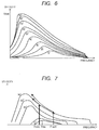
- FIG. 6 illustrates relationships between frequency and phase difference, and driving velocity of the vibration motor (referred to as frequency-velocity characteristic curve). Using a horizontal axis as frequency and a vertical axis as driving velocity, FIG. 6 illustrates frequency-velocity characteristic curves of the vibration motor in the case where the frequency varies with the phase difference fixed to 10 to 90 degrees.
- the driving velocity sharply changes relative to the frequency on a lower-frequency side from a frequency at which the highest velocity is reached (hereinafter also referred to as resonance frequency) with each phase difference. Therefore, to improve the controllability, it is generally desirable to control the vibration motor without using this frequency range.
- FIG. 7 illustrates loci of the driving velocity using both of phase difference control and frequency control in velocity characteristics of the vibration motor in the case where a frequency as a starting point (hereinafter also referred to as an activation frequency) is changed.
- FIG. 7 is drawn in the same manner as FIG. 6 .
- the frequency at phase difference control is set to a frequency FresH that is higher than a resonance frequency Fres with the phase difference of 10 degrees, and phase difference control is switched to frequency control with the phase difference of 90 degrees.
- the driving velocity follows a frequency-velocity locus as represented by a broken arrow.
- the broken arrow is located higher than the resonance frequency Fres also with the phase difference of 10 degrees, leading to stable control.
- the broken arrow follows a nonlinear locus. That is, in the frequency control domain, even when the frequency rises or lowers by a certain amount, the driving velocity of the vibration motor does not increase or decrease by a corresponding certain amount, which lowers the controllability.
- the frequency at phase difference control is set to a frequency FresL that is lower than the frequency FresH for the purpose of reducing the adverse effect of nonlinearity on the controllability in the frequency control domain
- the driving velocity follows a locus as represented by a solid arrow.
- the solid arrow has a narrower frequency control domain than the broken arrow, enabling reduction of the adverse effect of nonlinearity at frequency control.
- the frequency FresL at phase difference control is lower than the resonance frequency Fres with the phase difference of 10 degrees. For this reason, if the frequency is set to FresL at phase difference control, the operation of the vibration motor with a small phase difference may become unstable. Generally, the resonance frequency in frequency-velocity characteristics of the vibration motor is higher with the phase difference at which the low velocity is attained (phase difference of 10 degrees in FIG. 7 ) than with the phase difference at which the high velocity is attained (phase difference of 90 degrees in FIG. 7 ). For this reason, when the activation frequency is set in a low frequency region, there may be no choice but to perform control by using a frequency region lower than the resonance frequency in the frequency-velocity characteristic curve.
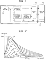
- FIG. 1 illustrates configuration of a vibration motor controller in accordance with this embodiment.
- FIG. 1 illustrates configuration of a vibration motor controller in accordance with this embodiment.
- main components of the present invention are described, and description of components that do not form features present invention is omitted.
- a vibration motor controller 100 controls driving of a vibration motor 103.
- a frequency determiner 101 determines frequency of a plurality of frequency signals inputted to the vibration motor 103. For example, the frequency is determined based on a difference between an output of a position detector 105 that detects the position of the vibration motor 103 and an output of a target input unit 106. Further, the lower-frequency side is determined from the activation frequency stored in an activation frequency memory 107.
- a phase difference determiner 102 determines the phase difference between plural frequency signals according to the frequency determined by the frequency determiner 101. A determination method will be described later in detail.
- An output unit 104 (controller) outputs the plurality of frequency signals to the vibration motor 103 based on the frequency determined by the frequency determiner 101 and the phase difference determined by the phase difference determiner 102.
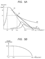
- FIG. 2 illustrates relationships between frequency and driving velocity of two frequency signals applied to the vibration motor, by using the phase difference as a parameter.
- the gradient of the driving velocity relative to the frequency is large in a frequency region lower than the resonance frequency, and thus this region is not used for driving control in consideration of the controllability.
- the driving velocity rapidly decreases at an end on the high-frequency side as illustrated in FIG. 2 (hereinafter also referred to as "steep drop characteristic” or “cliff drop phenomenon”) and therefore, this region is also not used for driving control in consideration of controllability.
- the region in the frequency-velocity characteristic curve, in which the driving velocity does not largely change with the change of the frequency is used for controlling, achieving good controllability.
- a range of the phase difference used for control is determined.
- the range of the phase difference for control is set to 0 to 90 degrees.
- a point P0 indicating a frequency F0 that is higher than the resonance frequency, out of frequencies (F0' F0) indicating a highest velocity V0 in a target control velocity range is identified ( FIG. 3A ).
- An activation frequency Fa2 that is higher than the resonance frequencies in all the frequency-velocity characteristic curves with respective phase differences and is lower than the high-frequency side exhibiting the steep drop characteristic is set, and a point P1 of the activation frequency Fa2 at the driving velocity of 0 is connected to the point P0 on the frequency-velocity characteristic curve with the predetermined phase difference (90 degrees).
- the activation frequency Fa2 is set such that a straight line P0-P1 does not cross any of the frequency-velocity characteristic curves with the respective phase differences in the frequency region lower than their resonance frequencies (ex. the line P0-P1 crosses if a frequency Fa1 is selected), and does not cross the frequency-velocity characteristic curve with the phase difference (here, 90 degrees) at which a highest velocity Vmax is attained (ex. the line P0-P1 crosses if a frequency Fa3 is selected).
- the straight line P1-P0 thus determined represents the linear relationship between frequency and driving velocity
- the driving velocity is controlled based on this relationship by changing the frequency, and therefore high controllability of the driving velocity relative to the frequency can be achieved.
- the phase difference needs to be changed with the change of the frequency so as to satisfy the relationship between frequency and phase difference on the straight line as illustrated in FIGS. 2 , 3A and 3B .
- the relationship between frequency and phase difference in the range of the frequency Fa2 to the frequency F0 (driving velocity 0 to V0), which satisfies the straight line P1-P0 as the control line ( FIG. 3B ), is held in the phase difference determiner 102.
- the relationship between frequency and phase difference in FIG. 3B in the form of a table, a formula, or the like, is held in the phase difference determiner 102, and the phase difference determiner 102 determines the phase difference outputted to the vibration motor according to the frequency, thereby linearly controlling the driving velocity in response to an input of frequency.
- the straight line P1-P0 that is the frequency-velocity control line illustrated in FIG. 3A should be set so as not to cross any of the frequency-velocity characteristic curves with respective phase differences in the frequency region lower than the resonance frequency, and not to cross the frequency-velocity characteristic curve with the phase difference at which the highest velocity is attained. Since the relationship between driving velocity and frequency is linear, the frequency corresponding to the highest velocity is the lowest frequency in the control frequency range.
- the phase difference corresponding to the highest velocity is not limited to the largest phase difference, as illustrated in FIG. 3B .
- the phase difference (70 degrees in FIG. 4A ) of the frequency-velocity characteristic curve at which the highest velocity is attained is not the phase difference (90 degrees in FIG. 4A ) of on the frequency-velocity characteristic curve at which the highest velocity is attained in the phase difference range used as the control range
- the phase difference is not necessarily largest at the highest velocity V0 in the control range, as illustrated in FIG. 4B .
- FIG. 4B as the frequency is lowered from the activation frequency, the phase difference increases once and then decreases, so that the frequency and the phase difference correspond to the highest velocity. Based on such frequency-velocity control line, the frequency and the driving velocity can be linearly controlled with high controllability.
- a vibration motor 103 in accordance with embodiment 2 of the present invention will be described below with reference to FIGS. 5A and 5B .
- the desired highest velocity V0 to the lowest velocity cannot be linearly controlled with respect to frequency.
- Configuration of the vibration motor in this embodiment is the same as that in Embodiment 1 and thus, description thereof is omitted.
- the range of the phase difference for control is set to 0 to 90 degrees.
- frequencies (F0', F0) indicating the highest velocity V0 on the frequency-velocity characteristic curve with a phase difference (here, 90 degrees) attaining the highest velocity are identified first, and then a point P0 indicating the frequency F0 that is higher than the resonance frequency is identified from the frequencies (F0', F0).
- an activation frequency that is higher than the resonance frequency and is lower than the high-frequency side exhibiting the steep drop characteristic is set.
- a straight line P0-P1 that connects the point P1 at the activation frequency and the driving velocity of 0 to the point P0 on the frequency-velocity characteristic curve with the phase difference of 90 degrees can linearly control the range of the driving velocity 0 to the highest velocity V0 with respect to the frequency in a following case.
- the straight line P0-P1 does not cross any of the frequency-velocity characteristic curves with respective phase differences in the frequency region lower than the resonance frequency (the line P0-P1 crosses in the case of selecting a frequency Fb2), and does not cross the frequency-velocity characteristic curve with the phase difference at which the highest velocity is attained (the line P0-P1 crosses in the case of selecting a frequency Fb3).
- the vibration motor having frequency-velocity characteristics as illustrated in FIG. 5A have no straight line P0-P1 that satisfies the above condition, a following frequency-velocity control line is adopted.
- an activation frequency Fb3 that is higher than the resonance frequency in any of frequency-velocity characteristic curves with respective phase differences and is lower than the high-frequency side exhibiting the steep drop characteristic is set, and a point P2 at the highest velocity is found such that a straight line connecting the point P1 to the point P1 at the activation frequency Fb3 does not cross the frequency-velocity characteristic curve with the phase difference of 90 degrees that exhibits the highest velocity, but makes contact with the straight line.
- the straight line P1-P2 is a tangent line of the frequency-velocity characteristic curve with the phase difference of 90 degrees at which the highest velocity is attained.
- this straight line is used as the frequency-velocity control line to control velocity
- the frequency-velocity characteristic curve with the phase difference of 90 degrees is used as the control line to change frequency with the phase difference kept constant (here, 90 degrees).
- a relationship between frequency and driving velocity in the range of the frequency Fb3 to the frequency Fb1 is linear.
- the relationship between frequency and driving velocity is not linear in the range of the frequency Fb1 to the frequency F0 (driving velocity V1 (first velocity) to V0) and however, can achieve controllability that can be acquired in the section of the straight line P1-P2.
- the straight line P1-P2 is tangent to the curve P2-P0, the straight line P1-P2 can be transitioned to the curve P2-P0 without causing sharp acceleration or deceleration, which enables smooth transition between the control domains.
- the phase difference needs to be changed with change of frequency so as to satisfy the relationship between frequency and phase difference on the control line P1-P0 as illustrated in FIG. 5A .
- the relationship between frequency and phase difference in the range of the frequency Fb3 to the frequency F0 (driving velocity 0 to V0), which satisfies the straight line P1-P0 as the control line ( FIG. 5B ) is held in the form of a table, formula, or the like in the phase difference determiner 102.
- phase difference determiner 102 determines the phase difference outputted to the vibration motor according to the frequency, thereby controlling the driving velocity on the lower-velocity side linearly and controlling the driving velocity on the higher-velocity side substantially linearly, in response to an input of frequency.
- the controller of the present invention can achieve both of controllability and stability with a small phase difference can be achieved while maintaining a wide dynamic range of the driving velocity.
- control line in Embodiment 1 as illustrated in FIG. 4A may be used as the frequency-velocity control line in the straight line P1-P2 in Embodiment 2.
- phase difference by determining phase difference according to the frequency, while using frequency-velocity characteristics higher than the resonance frequency even with a small phase difference, driving velocity can be controlled according to the frequency linearly or substantially linearly in the whole velocity control domain.
- the dynamic range of driving velocity can be made large by changing phase difference while changing the frequency from the activation frequency to the lower-frequency side.
- the used phase difference is 90 degrees (0 degrees to 90 degrees)
- the present invention is not limited to this.
- 80 degrees or 70 degrees can achieve the advantages of the present invention.
- phase difference is changed in the range of 0 degrees to 90 degrees
- any phase difference that can be changed to exhibit low velocity to high velocity may be used.
- a range of 90 degrees to 180 degrees or -90 degrees to 0 degrees can achieve the advantages of the present invention.
- phase difference at the frequency Fb3 in FIGS. 5A and 5B is set to 0 degree
- any phase difference that can acquire the lowest velocity necessary for the controller may be used, and the control velocity for achieving the advantages of the present invention does not necessarily include 0.
- the phase difference of 10 degrees may be set at the frequency Fb3, and a curve or straight line that is similar to that in FIG. 5A may be acquired based on a straight line connecting the point to the point P2 to achieve the advantages of the present invention.
- the activation frequency is set to Fb3
- any activation frequency that satisfies the above condition may be used.
- a frequency between the resonance frequency with the phase difference of 10 degrees and the frequency Fb3 is set as the activation frequency, and a straight line connecting the point to the point P2 as described above is a straight line that passes higher than the resonance frequency with each phase difference on frequency-velocity characteristics of the vibration motor, the advantages of the present invention can be achieved.
- the vibration motor controller in Embodiment 1 or 2 may be used as a driving motor controller for a lens apparatus including a movable optical member, and a vibration motor for driving the movable optical member as a driving unit.
- a driving motor controller for a lens apparatus including a movable optical member, and a vibration motor for driving the movable optical member as a driving unit.
- the movable optical member is a movable lens group
- an operating ring or an operating knob corresponds to the target input unit 106
- the frequency determiner 101 determines a frequency based on a difference between a target value from the target input unit 106 and a detection value from the detector 105 for detecting position of the movable lens group.
- the determined frequency is inputted to the phase difference determiner 102, the phase difference is determined based on the stored relationship between frequency and phase difference, and the vibration motor 103 is controlled based on the phase difference.
- the vibration motor controller in Embodiment 1 or 2 may be used as a driving motor controller for an image pickup apparatus including a lens apparatus that has a movable optical member and a vibration motor for driving the movable optical member as a driving unit, and an image pickup element for picking up an optical image formed by the lens apparatus. Also in this case, as in the case of applying the controller of the present invention to the lens apparatus, it is possible to provide the image pickup apparatus capable of producing the advantages present invention, that is, achieving both of controllability and stability with a small phase difference can be achieved while maintaining a wide dynamic range of the driving velocity.
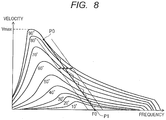
- Linear control of driving velocity in each embodiment of the present invention is not necessarily linear in a strict mathematical sense, and phase difference control and frequency control may be repeated in a range delimited by a double-headed arrow and oblique lines in FIG. 8 .
- the range illustrated in FIG. 8 is the range having a predetermined width on each of a lower frequency side and a higher frequency side of a straight line connecting P0 to P1.
- this range is the range having a width of ⁇ 10% or less, more preferably, ⁇ 6% or less of the width of the use frequency range with respect to the straight line connecting P0 to P1.
- the range illustrated in FIG. 8 is the range of ⁇ 0.4 kHz from the straight line connecting P0 to P1. Further, the range illustrated in FIG.
- this range is a range of ⁇ 10% or less, more preferably, ⁇ 6% or less of the highest velocity with respect to the straight line connecting P0 to P1.
- Linear control of the driving velocity in each embodiment of the present invention refers to characteristic that, in a qualitative manner, when the vibration motor is used for driving of the focus lens and the frequency determiner changes the frequency with a minimum resolution that can be determined by the frequency determiner, focal depth changing due to the change of velocity does not depart from a predetermined focal depth when the focus lens ideally drives.
- Embodiment(s) of the present invention can also be realized by a computer of a system or apparatus that reads out and executes computer executable instructions (e.g., one or more programs) recorded on a storage medium (which may also be referred to more fully as a 'non-transitory computer-readable storage medium') to perform the functions of one or more of the above-described embodiment(s) and/or that includes one or more circuits (e.g., application specific integrated circuit (ASIC)) for performing the functions of one or more of the above-described embodiment(s), and by a method performed by the computer of the system or apparatus by, for example, reading out and executing the computer executable instructions from the storage medium to perform the functions of one or more of the above-described embodiment(s) and/or controlling the one or more circuits to perform the functions of one or more of the above-described embodiment(s).
- computer executable instructions e.g., one or more programs
- a storage medium which may also be referred to more fully as
- the computer may comprise one or more processors (e.g., central processing unit (CPU), micro processing unit (MPU)) and may include a network of separate computers or separate processors to read out and execute the computer executable instructions.
- the computer executable instructions may be provided to the computer, for example, from a network or the storage medium.
- the storage medium may include, for example, one or more of a hard disk, a random-access memory (RAM), a read only memory (ROM), a storage of distributed computing systems, an optical disk (such as a compact disc (CD), digital versatile disc (DVD), or Blu-ray Disc (BD)TM), a flash memory device, a memory card, and the like.
Landscapes
- Physics & Mathematics (AREA)
- Engineering & Computer Science (AREA)
- General Physics & Mathematics (AREA)
- Power Engineering (AREA)
- Multimedia (AREA)
- Signal Processing (AREA)
- Optics & Photonics (AREA)
- General Electrical Machinery Utilizing Piezoelectricity, Electrostriction Or Magnetostriction (AREA)
- Lens Barrels (AREA)
Applications Claiming Priority (2)
| Application Number | Priority Date | Filing Date | Title |
|---|---|---|---|
| JP2015161869 | 2015-08-19 | ||
| JP2016149906A JP6723858B2 (ja) | 2015-08-19 | 2016-07-29 | 振動型モータ制御装置及びそれを有するレンズ装置及び撮像装置 |
Publications (2)
| Publication Number | Publication Date |
|---|---|
| EP3136587A2 true EP3136587A2 (de) | 2017-03-01 |
| EP3136587A3 EP3136587A3 (de) | 2017-05-03 |
Family
ID=56686610
Family Applications (1)
| Application Number | Title | Priority Date | Filing Date |
|---|---|---|---|
| EP16001794.3A Withdrawn EP3136587A3 (de) | 2015-08-19 | 2016-08-12 | Vibrationsmotorsteuerung und linsenvorrichtung und bildaufnahmevorrichtung damit |
Country Status (2)
| Country | Link |
|---|---|
| US (1) | US9715162B2 (de) |
| EP (1) | EP3136587A3 (de) |
Families Citing this family (1)
| Publication number | Priority date | Publication date | Assignee | Title |
|---|---|---|---|---|
| JP6720070B2 (ja) * | 2016-12-16 | 2020-07-08 | キヤノン株式会社 | 撮像装置及びその制御方法、プログラム |
Citations (3)
| Publication number | Priority date | Publication date | Assignee | Title |
|---|---|---|---|---|
| JP2008067441A (ja) * | 2006-09-05 | 2008-03-21 | Mizoue Project Japan:Kk | 超音波モータの制御装置、該方法、該プログラム及び記録媒体並びに超音波モータシステム |
| JP2011067035A (ja) | 2009-09-18 | 2011-03-31 | Canon Inc | 振動型モータ制御装置および光学機器 |
| US20140191691A1 (en) * | 2010-06-07 | 2014-07-10 | Canon Kabushiki Kaisha | Control apparatus of vibration-type actuator and control method of vibration-type actuator |
Family Cites Families (9)
| Publication number | Priority date | Publication date | Assignee | Title |
|---|---|---|---|---|
| JPS63178774A (ja) * | 1987-01-19 | 1988-07-22 | Canon Inc | 振動波モ−タ−の駆動回路 |
| JPH07170768A (ja) * | 1993-12-14 | 1995-07-04 | Nikon Corp | 超音波モータ |
| US5644199A (en) * | 1994-07-20 | 1997-07-01 | Matsushita Electric Industrial Co., Ltd. | Method for driving an ultrasonic motor |
| JP3437359B2 (ja) | 1996-01-08 | 2003-08-18 | キヤノン株式会社 | 振動波駆動装置の制御装置 |
| US5955819A (en) * | 1996-05-15 | 1999-09-21 | Canon Kabushiki Kaisha | Standing-wave vibration motor |
| JP4483899B2 (ja) * | 2007-06-21 | 2010-06-16 | 日産自動車株式会社 | アキシャルギャップ型回転電機の交流制御装置 |
| JP2010166736A (ja) | 2009-01-16 | 2010-07-29 | Olympus Corp | 超音波モータ |
| JP2011030285A (ja) * | 2009-07-21 | 2011-02-10 | Olympus Corp | 超音波モータ |
| JP6478680B2 (ja) * | 2015-02-12 | 2019-03-06 | キヤノン株式会社 | 制御装置、レンズ装置、および撮像装置 |
-
2016
- 2016-08-11 US US15/234,228 patent/US9715162B2/en not_active Expired - Fee Related
- 2016-08-12 EP EP16001794.3A patent/EP3136587A3/de not_active Withdrawn
Patent Citations (3)
| Publication number | Priority date | Publication date | Assignee | Title |
|---|---|---|---|---|
| JP2008067441A (ja) * | 2006-09-05 | 2008-03-21 | Mizoue Project Japan:Kk | 超音波モータの制御装置、該方法、該プログラム及び記録媒体並びに超音波モータシステム |
| JP2011067035A (ja) | 2009-09-18 | 2011-03-31 | Canon Inc | 振動型モータ制御装置および光学機器 |
| US20140191691A1 (en) * | 2010-06-07 | 2014-07-10 | Canon Kabushiki Kaisha | Control apparatus of vibration-type actuator and control method of vibration-type actuator |
Also Published As
| Publication number | Publication date |
|---|---|
| EP3136587A3 (de) | 2017-05-03 |
| US20170052429A1 (en) | 2017-02-23 |
| US9715162B2 (en) | 2017-07-25 |
Similar Documents
| Publication | Publication Date | Title |
|---|---|---|
| US11762189B2 (en) | Liquid lenses | |
| US20160226402A1 (en) | Drive control circuit that drives vibrator, driving method, vibration-type driving apparatus, and image pickup apparatus | |
| US10615719B2 (en) | Vibration motor controller, lens apparatus including the same, and image pickup apparatus including the same | |
| US10447176B2 (en) | Vibration type actuator control apparatus, apparatus having the same, and storage medium storing vibration type actuator control program | |
| US20130169854A1 (en) | Camera module, electronic device comprising the same and auto focus method | |
| JP6539048B2 (ja) | レンズ駆動装置及び駆動方法 | |
| JP7108451B2 (ja) | 駆動制御装置、デバイス、光学モジュール、駆動制御方法、およびプログラム | |
| JP6591662B2 (ja) | 速い自動焦点のためのレンズ駆動制御方法及びこれのための装置 | |
| EP3136587A2 (de) | Vibrationsmotorsteuerung und linsenvorrichtung und bildaufnahmevorrichtung damit | |
| US11967914B2 (en) | Vibration actuator control apparatus | |
| US9628694B2 (en) | Image pickup apparatus that drivingly controls lenses and control method therefor | |
| CN106469997B (zh) | 振动马达控制器以及透镜装置和图像拾取装置 | |
| EP3062507B1 (de) | Bildaufnahmegerät und methode zum kontrollieren eines bildaufnahmegeräts | |
| EP2841988B1 (de) | System und verfahren zu implementieren eine aktive dämpfung von schwingungen und vibrationen eines linseneinheit | |
| CN117111380A (zh) | 驱动控制装置、系统及方法、镜头装置及存储介质 | |
| KR20100033689A (ko) | 카메라모듈용 피에조 액추에이터의 구동장치 및 구동방법 | |
| US9979877B2 (en) | Image capturing apparatus, control method of the same, and storage medium | |
| US11463022B2 (en) | Driving control apparatus, driving apparatus and driving control method | |
| US11611294B2 (en) | Vibration driving device, apparatus equipped with vibration driving device, control device and control method for vibration actuator | |
| US20250080854A1 (en) | Control apparatus and control method therefor | |
| US20210099106A1 (en) | Control apparatus for vibration motor, vibration apparatus having the same, and control method of vibration motor | |
| US11689120B2 (en) | Control apparatus, control method, and driving apparatus of vibration type actuator | |
| JP2022148633A5 (de) | ||
| JP6378609B2 (ja) | 振動型モータ制御装置及びそれを有するレンズ装置、撮像装置、及び振動型モータの制御方法 | |
| US20260031746A1 (en) | Piezo actuator system and operating method thereof |
Legal Events
| Date | Code | Title | Description |
|---|---|---|---|
| PUAI | Public reference made under article 153(3) epc to a published international application that has entered the european phase |
Free format text: ORIGINAL CODE: 0009012 |
|
| AK | Designated contracting states |
Kind code of ref document: A2 Designated state(s): AL AT BE BG CH CY CZ DE DK EE ES FI FR GB GR HR HU IE IS IT LI LT LU LV MC MK MT NL NO PL PT RO RS SE SI SK SM TR |
|
| AX | Request for extension of the european patent |
Extension state: BA ME |
|
| PUAL | Search report despatched |
Free format text: ORIGINAL CODE: 0009013 |
|
| AK | Designated contracting states |
Kind code of ref document: A3 Designated state(s): AL AT BE BG CH CY CZ DE DK EE ES FI FR GB GR HR HU IE IS IT LI LT LU LV MC MK MT NL NO PL PT RO RS SE SI SK SM TR |
|
| AX | Request for extension of the european patent |
Extension state: BA ME |
|
| RIC1 | Information provided on ipc code assigned before grant |
Ipc: H04N 5/00 20110101ALI20170325BHEP Ipc: H02N 2/00 20060101ALI20170325BHEP Ipc: H02P 25/032 20160101AFI20170325BHEP Ipc: G02B 7/08 20060101ALI20170325BHEP Ipc: H04N 5/225 20060101ALI20170325BHEP Ipc: G02B 15/00 20060101ALI20170325BHEP Ipc: G02B 27/00 20060101ALI20170325BHEP Ipc: G02B 7/04 20060101ALI20170325BHEP |
|
| 17P | Request for examination filed |
Effective date: 20171103 |
|
| RBV | Designated contracting states (corrected) |
Designated state(s): AL AT BE BG CH CY CZ DE DK EE ES FI FR GB GR HR HU IE IS IT LI LT LU LV MC MK MT NL NO PL PT RO RS SE SI SK SM TR |
|
| 17Q | First examination report despatched |
Effective date: 20190722 |
|
| STAA | Information on the status of an ep patent application or granted ep patent |
Free format text: STATUS: THE APPLICATION HAS BEEN WITHDRAWN |
|
| 18W | Application withdrawn |
Effective date: 20201127 |