EP3136012A1 - Dispositif de depoussierage mobile - Google Patents
Dispositif de depoussierage mobile Download PDFInfo
- Publication number
- EP3136012A1 EP3136012A1 EP16185651.3A EP16185651A EP3136012A1 EP 3136012 A1 EP3136012 A1 EP 3136012A1 EP 16185651 A EP16185651 A EP 16185651A EP 3136012 A1 EP3136012 A1 EP 3136012A1
- Authority
- EP
- European Patent Office
- Prior art keywords
- filter
- fan
- dedusting device
- housing
- room air
- Prior art date
- Legal status (The legal status is an assumption and is not a legal conclusion. Google has not performed a legal analysis and makes no representation as to the accuracy of the status listed.)
- Pending
Links
Images

Classifications
-
- F—MECHANICAL ENGINEERING; LIGHTING; HEATING; WEAPONS; BLASTING
- F24—HEATING; RANGES; VENTILATING
- F24F—AIR-CONDITIONING; AIR-HUMIDIFICATION; VENTILATION; USE OF AIR CURRENTS FOR SCREENING
- F24F8/00—Treatment, e.g. purification, of air supplied to human living or working spaces otherwise than by heating, cooling, humidifying or drying
- F24F8/10—Treatment, e.g. purification, of air supplied to human living or working spaces otherwise than by heating, cooling, humidifying or drying by separation, e.g. by filtering
- F24F8/108—Treatment, e.g. purification, of air supplied to human living or working spaces otherwise than by heating, cooling, humidifying or drying by separation, e.g. by filtering using dry filter elements
-
- F—MECHANICAL ENGINEERING; LIGHTING; HEATING; WEAPONS; BLASTING
- F24—HEATING; RANGES; VENTILATING
- F24F—AIR-CONDITIONING; AIR-HUMIDIFICATION; VENTILATION; USE OF AIR CURRENTS FOR SCREENING
- F24F13/00—Details common to, or for air-conditioning, air-humidification, ventilation or use of air currents for screening
- F24F13/20—Casings or covers
-
- F—MECHANICAL ENGINEERING; LIGHTING; HEATING; WEAPONS; BLASTING
- F24—HEATING; RANGES; VENTILATING
- F24F—AIR-CONDITIONING; AIR-HUMIDIFICATION; VENTILATION; USE OF AIR CURRENTS FOR SCREENING
- F24F8/00—Treatment, e.g. purification, of air supplied to human living or working spaces otherwise than by heating, cooling, humidifying or drying
- F24F8/10—Treatment, e.g. purification, of air supplied to human living or working spaces otherwise than by heating, cooling, humidifying or drying by separation, e.g. by filtering
-
- B—PERFORMING OPERATIONS; TRANSPORTING
- B01—PHYSICAL OR CHEMICAL PROCESSES OR APPARATUS IN GENERAL
- B01D—SEPARATION
- B01D46/00—Filters or filtering processes specially modified for separating dispersed particles from gases or vapours
- B01D46/0002—Casings; Housings; Frame constructions
- B01D46/0005—Mounting of filtering elements within casings, housings or frames
-
- B—PERFORMING OPERATIONS; TRANSPORTING
- B01—PHYSICAL OR CHEMICAL PROCESSES OR APPARATUS IN GENERAL
- B01D—SEPARATION
- B01D46/00—Filters or filtering processes specially modified for separating dispersed particles from gases or vapours
- B01D46/0027—Filters or filtering processes specially modified for separating dispersed particles from gases or vapours with additional separating or treating functions
- B01D46/0028—Filters or filtering processes specially modified for separating dispersed particles from gases or vapours with additional separating or treating functions provided with antibacterial or antifungal means
-
- B—PERFORMING OPERATIONS; TRANSPORTING
- B01—PHYSICAL OR CHEMICAL PROCESSES OR APPARATUS IN GENERAL
- B01D—SEPARATION
- B01D46/00—Filters or filtering processes specially modified for separating dispersed particles from gases or vapours
- B01D46/56—Filters or filtering processes specially modified for separating dispersed particles from gases or vapours with multiple filtering elements, characterised by their mutual disposition
- B01D46/62—Filters or filtering processes specially modified for separating dispersed particles from gases or vapours with multiple filtering elements, characterised by their mutual disposition connected in series
Definitions
- the present invention relates to a mobile dedusting device for cleaning polluted room air, comprising a housing in which at least one filter element is received, with at least one fan for sucking the polluted room air, with an inlet opening for the polluted room air and with an outlet opening for purified room air.
- a generic mobile dedusting device is from the German utility model DE 92 06 851 U1 known. This dust removal device operates in a first main filter stage according to the cyclone principle. In an additional filter stage a fine dust filter is connected downstream. This known dedusting device is complex and has comparatively large external dimensions due to the numerous components installed.
- the object of the present invention is to develop a generic dedusting device such that it works as efficiently as possible with a simple, compact design and low energy consumption.
- the inlet opening extends over the qeticianen cross-section of the housing, that the outlet opening is formed as at least one housing wall open clean air space and disposed above a lower floor of the housing, that in the housing above the clean air space an intermediate bottom is received, in which the at least one fan is mounted, that in the housing above the false floor a support shoulder is provided, on which rests at least one main filter filter holder, and that on the filter holder at least one in a Frame held pre-filter rests.
- the main advantage of the dedusting device according to the invention is that no pipe or hose lines are provided for the transport of the room air, along which pressure losses can occur. Rather, the polluted room air over the entire cross-section of the housing of the dedusting device according to the invention (that is, over the entire outwardly facing surface of the prefilter) sucked, and the purified room air is delivered near the ground in the radial direction to the outside, the clean air space as an outlet for the purified room air is effective.
- the only pressure losses during operation of the dedusting device according to the invention are essentially caused by the main filter.
- This constructive measure according to the invention has the consequence that the "system characteristic point", i. the optimum operating point of the mobile dedusting device according to the invention is not adversely affected by such, caused by pipe or hose lines pressure losses. Rather, in the dedusting device according to the invention, the "system characteristic point" corresponds completely to the characteristic curve of the fan used.
- the dedusting device according to the invention operates with minimum power consumption particularly efficient and quiet.
- the cleaned, comparatively warm room air flows out of the dedusting device according to the invention near the bottom, it contributes at least in the discharge area to an improved heat distribution of the room air as a whole.
- a cavity enclosed by a bottom plate cavity for receiving mechanical and electrical components for operating the dedusting device is formed below the subfloor, so that for the dedusting device according to the invention a particularly compact design can be realized.
- a pressure measuring device operatively connected to the fan is provided above the intermediate bottom in order to signal a timely filter change in the event of an excessive pressure loss caused by a clogged filter.
- the fan is designed as a radial fan with backward curved blades.
- Such fans have proven to be particularly efficient and for the deduster according to the invention as outstandingly suitable.
- the main filter used is preferably a fine dust filter and / or particle filter, depending on the quality of the room air to be cleaned.
- the pre-filter is expediently a coarse dust filter.
- a further advantageous embodiment provides that a device for emitting UV radiation is provided below the main filter in order to prevent any possible contamination of the filter.
- the efficiency of the dedusting device according to the invention is optimized in such a way that the entire dedusting device is dimensioned according to the characteristics of the fan used. It is desirable that at least one 1: 1 room air exchange occur, i. Within one hour, the entire room air of a room is exchanged.
- the filter elements with filter surface and the housing dimensions are ultimately aligned with the characteristic curve of the fan.
- the filter area or the filter volume of freshly inserted main filter are designed so that during operation of the fan with 75% to 90% of its maximum power, a pressure loss determined by the main filter is generated. This pressure loss corresponds to the characteristic curve of the fan to the manufacturer defined first operating point of the fan.
- the filter area or the filter volume of the main filter is designed so that this operating point defines an added filter capacity of the main filter and pre-filter in cubic meters of room air per hour, which is below the possible maximum throughput of the filters for the room air is.
- a higher separation efficiency is generated than previously known at a lower pressure loss, the energy consumption of the dedusting device according to the invention is significantly reduced.
- the desired pressure build-up thus takes place with minimal power consumption and at the same time with minimal noise in db (A).
- Another advantage is that a possibly existing warning display for changing the main filter based on the characteristic curve of the fan can be set.
- Based on a pressure measuring device provided in the housing the pressure loss at which a filter change should take place can be measured accurately.
- the warning display is activated.
- An additional advantage of the de-dusting device operated according to the invention is that it can be built much more compact than known in the prior art. This is possible both due to the efficiency with which the dedusting device according to the invention works, as well as due to the simple design without pipe or hose lines.
- a mobile dedusting apparatus according to the invention is obtained, which operates efficiently, quietly and energy-saving.
- the dedusting device according to the invention also allows flexible use by the customer, who can combine two or more mobile dedusting devices according to the invention, depending on the size of the room, due to the high degree of effectiveness. This is usually much cheaper than providing a single large appliance.
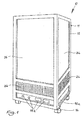
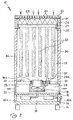
- FIGS. 1 and 2 show the basic structure of an embodiment of a mobile dedusting device 10 according to the invention.
- the dedusting device 10 has a housing 11.
- the housing 11 has a housing frame 12, which consists in the embodiment of an aluminum material.
- a bottom plate 13 is provided, which closes the housing 11 to the outside and is provided in the embodiment with rollers 14 in order to move the dedusting device 10 comfortably.
- an underbody 15 is received in the housing frame 12.
- a cavity 16 is formed, in which mechanical and electrical components are included for operation of the dedusting device 10.
- the cavity 16 is closed on all sides by wall elements 16a, wherein a wall element 16a is provided with controls 16b, for example.
- an intermediate bottom 17 is received in the housing frame 12.
- a fan 18 is fixed, which projects into the filter chamber 19 formed above the intermediate bottom 17.
- the fan 18 is sealed by a seal 18a to prevent ambient air outside the fan 18 from flowing into the clean air space 23 (see below).
- the fan 18 is in the embodiment of a centrifugal fan with backward curved blades.
- Such fans are, for example, commercially available as EC centrifugal fans from the series "GreenTech" of the company ebm-pabst Germany.
- a pressure gauge 21 is fixed in the intermediate bottom 17, which is in operative connection with the fan 18 in a conventional manner.
- one or more UV lamps 22 may further be arranged, which evtll to kill. serve germs occurring.
- the pressure gauge 21 is like the fan 18 with a seal 21 a provided.
- the cavity formed by the underbody 15 and the intermediate bottom 17 is designed as a clean air space 23, since the fan 18 transports the cleaned room air through the intermediate bottom 17 into the clean air space 23.
- the clean air space 23 is provided in the exemplary embodiment on three of its sides with a grid 24 through which the purified room air flows into the open air. The clean air space 23 thus acts as an outlet for the purified room air.
- a circumferential support shoulder 25 is provided in the embodiment in the vicinity of the upper end of the housing frame 12.
- the support shoulder 25 is formed integrally with a filter frame 26, which forms the upper part of the housing frame 12.
- the support shoulder 25 serves to support a filter holder 27, which carries a main filter 28.
- the main filter 28 is designed in the embodiment as a fine dust filter of the particle filter class F9, preferably as a pocket filter.
- the particle filter class is of course freely selectable depending on the requirements of the individual case.
- the filter frame 26 also receives a pre-filter 29, which in turn sits in a frame 31 which rests on the filter holder 27.
- the pre-filter 29 is designed in the embodiment as a coarse dust filter of the particle filter class G4.
- the particle filter class (eg G3 to M5) is, of course, freely selectable depending on the requirements of the individual case.
- the filters used correspond in the exemplary embodiment of DIN EN 779: 2012 and DIN EN 1822 according to the provisions of VDI 6022-4.3.9 .. They are particularly water-repellent to prevent microbial contamination.
- Such filters are manufactured, for example, by the German companies HS Gutbau GmbH, Kiel and Kalthoff Gutfilter und Filtermedien GmbH, Selm.
- the pre-filter 29 is covered with a cover grille 32. Since the air-permeable grille extends over the entire cross-section of the housing frame 12, this acts at its upper free end as an inlet opening 33 for the polluted room air.
- the filter chamber 19 is closed by means of housing walls 34 to the outside.
- the housing walls 34 in the exemplary embodiment of aluminum composite plates with a core made of a plastic.
- Such aluminum composite panels are, for example, under the brand "DIBOND ⁇ " of the company 3A Composites GmbH, Singen, commercially available.
- the room air is thus transported over a large area in the vertical direction from top to bottom during the cleaning process, with pipe or hose lines are not needed.
- the cleaned room air is directed radially outward and flows on three sides of the dedusting device 10 (over an angle of 270 degrees) near the ground to the outside.
- the pressure gauge 21 is used to measure the pressure loss in the filter chamber 19, which increases with increasing contamination of the main filter 28. At a defined, preset pressure loss sends the pressure gauge 21 in a conventional manner, a signal to a warning device, which indicates the necessary change of the main filter 28 optically and / or acoustically. The degree of contamination of the pre-filter 29, however, is optically controlled.
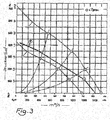
- a radial fan with a backward curved blade which shows the performance characteristics according to line B in FIG. 3 has and reaches a maximum flow rate of 1,400 m 3 / h, is optimally suitable for a mobile dedusting device 10 according to the invention of the following design: External dimensions (L ⁇ W ⁇ H) in cm: 46 ⁇ 46 ⁇ 89 Volume of filter chamber 19: 0.11 m 3 Dimensions of pre-filter 29 (G4, filter cell) in mm: 390 ⁇ 390 ⁇ 47 Dimensions of the main filter 28 (F9, Pocket Feeder) in mm: 390 ⁇ 390 ⁇ 500 Initial filter performance of both filters combined: 1,200 m 3 / h
- the dimensions of the main filter 28 and the filter chamber 19 are dimensioned so that an initial filter performance of 1,200 m 3 air per hour is achieved and an initial pressure drop of 130 Pascal (+/- 20 Pascal) results.
- This starting point corresponds to the point 2 of the line B in FIG. 3 ,
- the fan 18 reaches only 75% to 90% of its rated power and develops a noise level of only 61 to 66 db (A).
- the point 2 on the line B moves to the left, that is, due to the increasing pollution of the main filter 28, the pressure loss increases.
- the power of the fan 18 must be continuously increased.
- the pressure gauge 21 transmits a signal to a warning device to indicate the necessary change of the main filter 28.
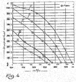
- a radial fan with a backward curved blade which shows the performance characteristics according to line B in FIG. 4 and reaches a maximum flow rate of 3,700 m 3 / h, is optimally suitable for a mobile dedusting device 10 according to the invention of the following design: External dimensions (L ⁇ W ⁇ H) in cm: 66 ⁇ 66 ⁇ 120 Volume of filter chamber 19: 0.29 m 3 Dimensions of pre-filter 29 (G4, filter cell) in mm: 592 ⁇ 592 ⁇ 47 Dimensions of main filter 28 (F9, pocket filter) in mm: 592 ⁇ 592 ⁇ 600 Initial filter performance of both filters combined: 3,000 m 3 / h
- the dimensions of the main filter 28 and the filter chamber 19 are dimensioned so that an initial filter capacity of 3,000 m 3 of air per hour is achieved and an initial pressure loss of 150 Pascal (+/- 20 Pascal) results.
- This starting point corresponds to the point 2 of the line B in FIG. 4 .
- the fan 18 reaches only 75% to 90% of its rated power and develops a noise level of only 63 to 68 db (A).
- the point 2 on the line B moves to the left, that is, due to the increasing contamination of the main filter 28, the pressure loss increases.
- the power of the fan 18 must be continuously increased.
- the pressure gauge 21 transmits a signal to a warning device to indicate the necessary change of the main filter 28.
- this dedusting device 10 With two or more copies of this dedusting device 10 according to the invention, in particular the room air of large rooms can be cleaned efficiently, quietly and energy-saving. With a room size of, for example, 6000m 3 , two of these dedusting devices 10 are much better than a large, in doubt stationary system with an initial filter capacity of 6000m 3 / h.
- a centrifugal fan with a backward curved blade, which shows the performance characteristics according to line A in FIG. 5 has a maximum flow of 700 m 3 / h is optimal suitable for a mobile dedusting device 10 according to the invention of the following design: External dimensions (L ⁇ W ⁇ H) in cm: 34 ⁇ 34 ⁇ 67 Volume of filter chamber 19: 0.042 m 3 Dimensions of pre-filter 29 (G4, filter cell) in mm: 287 ⁇ 287 ⁇ 47 Dimensions of main filter 28 (F9, pocket filter) in mm: 287 ⁇ 287 ⁇ 300 Initial filter performance of both filters combined: 500 m 3 / h
- the dimensions of the main filter 28 and the filter chamber 19 are dimensioned so that an initial filter performance of 500 m 3 air per hour is achieved and an initial pressure drop of 140 Pascal (+/- 20 Pascal) results.
- This starting point corresponds to the point 2 of the line A in FIG. 5 .
- the fan 18 reaches only 75% to 90% of its rated power and develops a noise level of just 59 db (A).
- the point 2 on the line A moves to the left, that is, due to the increasing contamination of the main filter 28, the pressure loss increases.
- the power of the fan 18 must be continuously increased.
- the pressure gauge 21 transmits a signal to a warning device to indicate the necessary change of the main filter 28.
- This small device is particularly well suited for the use of a Schwebstofffilters, eg. A HEPA filter as the main filter.
- This dedusting device 10 according to the invention can also be used as a table device without rollers 14.
Landscapes
- Engineering & Computer Science (AREA)
- Chemical & Material Sciences (AREA)
- Combustion & Propulsion (AREA)
- Mechanical Engineering (AREA)
- General Engineering & Computer Science (AREA)
- Filtering Of Dispersed Particles In Gases (AREA)
Applications Claiming Priority (1)
| Application Number | Priority Date | Filing Date | Title |
|---|---|---|---|
| DE102015010979.0A DE102015010979A1 (de) | 2015-08-26 | 2015-08-26 | Mobile Entstaubungsvorrichtung |
Publications (1)
| Publication Number | Publication Date |
|---|---|
| EP3136012A1 true EP3136012A1 (fr) | 2017-03-01 |
Family
ID=56800224
Family Applications (1)
| Application Number | Title | Priority Date | Filing Date |
|---|---|---|---|
| EP16185651.3A Pending EP3136012A1 (fr) | 2015-08-26 | 2016-08-25 | Dispositif de depoussierage mobile |
Country Status (2)
| Country | Link |
|---|---|
| EP (1) | EP3136012A1 (fr) |
| DE (1) | DE102015010979A1 (fr) |
Cited By (3)
| Publication number | Priority date | Publication date | Assignee | Title |
|---|---|---|---|---|
| CN108548244A (zh) * | 2018-04-12 | 2018-09-18 | 徐波 | 新型自控除尘空气净化装置 |
| GB2597827A (en) * | 2020-06-08 | 2022-02-09 | Spark Product Creation Ltd | Air-conditioner |
| US11708986B1 (en) * | 2022-07-12 | 2023-07-25 | Intellytic Ventures Ltd | Smart IoT energy saving sound wave air filter system and use for air purifiers and a method of air filtration thereof |
Families Citing this family (1)
| Publication number | Priority date | Publication date | Assignee | Title |
|---|---|---|---|---|
| DE102019112992A1 (de) * | 2019-05-16 | 2020-11-19 | Keller Lufttechnik Gmbh + Co. Kg | Filtereinheit |
Citations (3)
| Publication number | Priority date | Publication date | Assignee | Title |
|---|---|---|---|---|
| DE9206851U1 (fr) | 1992-05-21 | 1992-08-06 | Bhsu Luft- Und Umwelttechnik Gmbh, 3418 Uslar, De | |
| US20100058927A1 (en) * | 2006-07-14 | 2010-03-11 | Freshman Ab | Air filter arrangement and a method for manufacturing the same |
| US20140238243A1 (en) * | 2013-02-27 | 2014-08-28 | Kip Jardine | Apparatus for filtering air |
Family Cites Families (3)
| Publication number | Priority date | Publication date | Assignee | Title |
|---|---|---|---|---|
| US5399319A (en) * | 1993-08-02 | 1995-03-21 | Vector Technologies Ltd. | Apparatus for filtering air and for creating a positive/negative pressure |
| US7531141B2 (en) * | 2006-10-12 | 2009-05-12 | Airinspace B.V. | Mobile air decontamination and purification unit |
| DE102009053505A1 (de) * | 2009-11-16 | 2011-05-19 | Wu, Fu-Chi, Northridge | Luftreiniger |
-
2015
- 2015-08-26 DE DE102015010979.0A patent/DE102015010979A1/de not_active Withdrawn
-
2016
- 2016-08-25 EP EP16185651.3A patent/EP3136012A1/fr active Pending
Patent Citations (3)
| Publication number | Priority date | Publication date | Assignee | Title |
|---|---|---|---|---|
| DE9206851U1 (fr) | 1992-05-21 | 1992-08-06 | Bhsu Luft- Und Umwelttechnik Gmbh, 3418 Uslar, De | |
| US20100058927A1 (en) * | 2006-07-14 | 2010-03-11 | Freshman Ab | Air filter arrangement and a method for manufacturing the same |
| US20140238243A1 (en) * | 2013-02-27 | 2014-08-28 | Kip Jardine | Apparatus for filtering air |
Cited By (4)
| Publication number | Priority date | Publication date | Assignee | Title |
|---|---|---|---|---|
| CN108548244A (zh) * | 2018-04-12 | 2018-09-18 | 徐波 | 新型自控除尘空气净化装置 |
| CN108548244B (zh) * | 2018-04-12 | 2020-06-16 | 谢飞鹏 | 自控除尘空气净化装置 |
| GB2597827A (en) * | 2020-06-08 | 2022-02-09 | Spark Product Creation Ltd | Air-conditioner |
| US11708986B1 (en) * | 2022-07-12 | 2023-07-25 | Intellytic Ventures Ltd | Smart IoT energy saving sound wave air filter system and use for air purifiers and a method of air filtration thereof |
Also Published As
| Publication number | Publication date |
|---|---|
| DE102015010979A1 (de) | 2017-03-02 |
Similar Documents
| Publication | Publication Date | Title |
|---|---|---|
| DE102013110631B4 (de) | Vorrichtung zum Reinigen der Raumluft | |
| EP3052866B1 (fr) | Appareil de purification d'air à purification de l'ozone et des poussières fines | |
| EP3136012A1 (fr) | Dispositif de depoussierage mobile | |
| DE102005020400A1 (de) | Einrichtung zum Filtern von extrem feinem Staub | |
| DE102015005865B4 (de) | Gerät zur Trocknung von Dämmschichten von Fußböden im Unterdruckverfahren | |
| DE60130105T2 (de) | Verfahren und vorrichtung zur luftfiltration | |
| EP0332605B1 (fr) | Dispositif de ventilation pour vêtement de protection | |
| DE1148725B (de) | Klimaanlage | |
| DE202020105240U1 (de) | Luftreinigungsvorrichtung zum Filtern von Raumluft | |
| DE1604296C3 (de) | Lüftungsanlage | |
| DE4300830A1 (de) | Steinstaubabsaugung | |
| DE202020106913U1 (de) | Luftreinigungsvorrichtung zur Reinigung von Raumluft | |
| EP1891846A2 (fr) | Armoire electrique | |
| EP2645009A2 (fr) | Installation dýaération | |
| DE3719734A1 (de) | Filteraggregat | |
| EP2181583A2 (fr) | Procédé et dispositif d'aération | |
| EP3984566B1 (fr) | Dispositif d'éclairage d'hygiène | |
| EP2375180A2 (fr) | Dispositif de déshumidification | |
| DE19750276A1 (de) | Filteranlage | |
| DE19601486A1 (de) | Lufttechnische Einrichtung für die Konditionierung der Atemluft an einem industriellen Arbeitsplatz | |
| DE102015108698A1 (de) | Luftreiniger zum Reinigen von Raumluft und von Frischluft | |
| DE102021200212A1 (de) | Raumluftreinigungsvorrichtung | |
| DE102020002180A1 (de) | System zur belüftung von individuellen arbeitsplätzen zur vermeidung von tröpfcheninfektionen | |
| AT411490B (de) | Befestigungsanordnung für ventilator | |
| DE102022119859A1 (de) | Dunstabzugseinrichtung und Verfahren zum Betreiben |
Legal Events
| Date | Code | Title | Description |
|---|---|---|---|
| PUAI | Public reference made under article 153(3) epc to a published international application that has entered the european phase |
Free format text: ORIGINAL CODE: 0009012 |
|
| STAA | Information on the status of an ep patent application or granted ep patent |
Free format text: STATUS: THE APPLICATION HAS BEEN PUBLISHED |
|
| AK | Designated contracting states |
Kind code of ref document: A1 Designated state(s): AL AT BE BG CH CY CZ DE DK EE ES FI FR GB GR HR HU IE IS IT LI LT LU LV MC MK MT NL NO PL PT RO RS SE SI SK SM TR |
|
| AX | Request for extension of the european patent |
Extension state: BA ME |
|
| STAA | Information on the status of an ep patent application or granted ep patent |
Free format text: STATUS: REQUEST FOR EXAMINATION WAS MADE |
|
| 17P | Request for examination filed |
Effective date: 20170831 |
|
| RBV | Designated contracting states (corrected) |
Designated state(s): AL AT BE BG CH CY CZ DE DK EE ES FI FR GB GR HR HU IE IS IT LI LT LU LV MC MK MT NL NO PL PT RO RS SE SI SK SM TR |
|
| STAA | Information on the status of an ep patent application or granted ep patent |
Free format text: STATUS: EXAMINATION IS IN PROGRESS |
|
| 17Q | First examination report despatched |
Effective date: 20200710 |
|
| STAA | Information on the status of an ep patent application or granted ep patent |
Free format text: STATUS: EXAMINATION IS IN PROGRESS |