EP3136012A1 - Mobile dedusting device - Google Patents
Mobile dedusting device Download PDFInfo
- Publication number
- EP3136012A1 EP3136012A1 EP16185651.3A EP16185651A EP3136012A1 EP 3136012 A1 EP3136012 A1 EP 3136012A1 EP 16185651 A EP16185651 A EP 16185651A EP 3136012 A1 EP3136012 A1 EP 3136012A1
- Authority
- EP
- European Patent Office
- Prior art keywords
- filter
- fan
- dedusting device
- housing
- room air
- Prior art date
- Legal status (The legal status is an assumption and is not a legal conclusion. Google has not performed a legal analysis and makes no representation as to the accuracy of the status listed.)
- Withdrawn
Links
- 238000011045 prefiltration Methods 0.000 claims abstract description 15
- 238000004140 cleaning Methods 0.000 claims abstract description 4
- 239000000428 dust Substances 0.000 claims description 10
- 230000005855 radiation Effects 0.000 claims description 2
- 239000003570 air Substances 0.000 description 39
- 239000002245 particle Substances 0.000 description 7
- 238000011109 contamination Methods 0.000 description 6
- 238000005265 energy consumption Methods 0.000 description 5
- 238000010276 construction Methods 0.000 description 4
- 238000000926 separation method Methods 0.000 description 4
- XAGFODPZIPBFFR-UHFFFAOYSA-N aluminium Chemical compound [Al] XAGFODPZIPBFFR-UHFFFAOYSA-N 0.000 description 3
- 229910052782 aluminium Inorganic materials 0.000 description 3
- 239000002131 composite material Substances 0.000 description 3
- 230000032258 transport Effects 0.000 description 2
- 101150103877 Selenom gene Proteins 0.000 description 1
- 230000002411 adverse Effects 0.000 description 1
- 239000012080 ambient air Substances 0.000 description 1
- 244000052616 bacterial pathogen Species 0.000 description 1
- 238000011161 development Methods 0.000 description 1
- 230000018109 developmental process Effects 0.000 description 1
- 238000010410 dusting Methods 0.000 description 1
- 239000012535 impurity Substances 0.000 description 1
- 239000000463 material Substances 0.000 description 1
- 238000000034 method Methods 0.000 description 1
- 230000000813 microbial effect Effects 0.000 description 1
- 239000005871 repellent Substances 0.000 description 1
Images

Classifications
-
- F—MECHANICAL ENGINEERING; LIGHTING; HEATING; WEAPONS; BLASTING
- F24—HEATING; RANGES; VENTILATING
- F24F—AIR-CONDITIONING; AIR-HUMIDIFICATION; VENTILATION; USE OF AIR CURRENTS FOR SCREENING
- F24F8/00—Treatment, e.g. purification, of air supplied to human living or working spaces otherwise than by heating, cooling, humidifying or drying
- F24F8/10—Treatment, e.g. purification, of air supplied to human living or working spaces otherwise than by heating, cooling, humidifying or drying by separation, e.g. by filtering
- F24F8/108—Treatment, e.g. purification, of air supplied to human living or working spaces otherwise than by heating, cooling, humidifying or drying by separation, e.g. by filtering using dry filter elements
-
- F—MECHANICAL ENGINEERING; LIGHTING; HEATING; WEAPONS; BLASTING
- F24—HEATING; RANGES; VENTILATING
- F24F—AIR-CONDITIONING; AIR-HUMIDIFICATION; VENTILATION; USE OF AIR CURRENTS FOR SCREENING
- F24F13/00—Details common to, or for air-conditioning, air-humidification, ventilation or use of air currents for screening
- F24F13/20—Casings or covers
-
- F—MECHANICAL ENGINEERING; LIGHTING; HEATING; WEAPONS; BLASTING
- F24—HEATING; RANGES; VENTILATING
- F24F—AIR-CONDITIONING; AIR-HUMIDIFICATION; VENTILATION; USE OF AIR CURRENTS FOR SCREENING
- F24F8/00—Treatment, e.g. purification, of air supplied to human living or working spaces otherwise than by heating, cooling, humidifying or drying
- F24F8/10—Treatment, e.g. purification, of air supplied to human living or working spaces otherwise than by heating, cooling, humidifying or drying by separation, e.g. by filtering
-
- B—PERFORMING OPERATIONS; TRANSPORTING
- B01—PHYSICAL OR CHEMICAL PROCESSES OR APPARATUS IN GENERAL
- B01D—SEPARATION
- B01D46/00—Filters or filtering processes specially modified for separating dispersed particles from gases or vapours
- B01D46/0002—Casings; Housings; Frame constructions
- B01D46/0005—Mounting of filtering elements within casings, housings or frames
-
- B—PERFORMING OPERATIONS; TRANSPORTING
- B01—PHYSICAL OR CHEMICAL PROCESSES OR APPARATUS IN GENERAL
- B01D—SEPARATION
- B01D46/00—Filters or filtering processes specially modified for separating dispersed particles from gases or vapours
- B01D46/0027—Filters or filtering processes specially modified for separating dispersed particles from gases or vapours with additional separating or treating functions
- B01D46/0028—Filters or filtering processes specially modified for separating dispersed particles from gases or vapours with additional separating or treating functions provided with antibacterial or antifungal means
-
- B—PERFORMING OPERATIONS; TRANSPORTING
- B01—PHYSICAL OR CHEMICAL PROCESSES OR APPARATUS IN GENERAL
- B01D—SEPARATION
- B01D46/00—Filters or filtering processes specially modified for separating dispersed particles from gases or vapours
- B01D46/56—Filters or filtering processes specially modified for separating dispersed particles from gases or vapours with multiple filtering elements, characterised by their mutual disposition
- B01D46/62—Filters or filtering processes specially modified for separating dispersed particles from gases or vapours with multiple filtering elements, characterised by their mutual disposition connected in series
Definitions
- the present invention relates to a mobile dedusting device for cleaning polluted room air, comprising a housing in which at least one filter element is received, with at least one fan for sucking the polluted room air, with an inlet opening for the polluted room air and with an outlet opening for purified room air.
- a generic mobile dedusting device is from the German utility model DE 92 06 851 U1 known. This dust removal device operates in a first main filter stage according to the cyclone principle. In an additional filter stage a fine dust filter is connected downstream. This known dedusting device is complex and has comparatively large external dimensions due to the numerous components installed.
- the object of the present invention is to develop a generic dedusting device such that it works as efficiently as possible with a simple, compact design and low energy consumption.
- the inlet opening extends over the qeticianen cross-section of the housing, that the outlet opening is formed as at least one housing wall open clean air space and disposed above a lower floor of the housing, that in the housing above the clean air space an intermediate bottom is received, in which the at least one fan is mounted, that in the housing above the false floor a support shoulder is provided, on which rests at least one main filter filter holder, and that on the filter holder at least one in a Frame held pre-filter rests.
- the main advantage of the dedusting device according to the invention is that no pipe or hose lines are provided for the transport of the room air, along which pressure losses can occur. Rather, the polluted room air over the entire cross-section of the housing of the dedusting device according to the invention (that is, over the entire outwardly facing surface of the prefilter) sucked, and the purified room air is delivered near the ground in the radial direction to the outside, the clean air space as an outlet for the purified room air is effective.
- the only pressure losses during operation of the dedusting device according to the invention are essentially caused by the main filter.
- This constructive measure according to the invention has the consequence that the "system characteristic point", i. the optimum operating point of the mobile dedusting device according to the invention is not adversely affected by such, caused by pipe or hose lines pressure losses. Rather, in the dedusting device according to the invention, the "system characteristic point" corresponds completely to the characteristic curve of the fan used.
- the dedusting device according to the invention operates with minimum power consumption particularly efficient and quiet.
- the cleaned, comparatively warm room air flows out of the dedusting device according to the invention near the bottom, it contributes at least in the discharge area to an improved heat distribution of the room air as a whole.
- a cavity enclosed by a bottom plate cavity for receiving mechanical and electrical components for operating the dedusting device is formed below the subfloor, so that for the dedusting device according to the invention a particularly compact design can be realized.
- a pressure measuring device operatively connected to the fan is provided above the intermediate bottom in order to signal a timely filter change in the event of an excessive pressure loss caused by a clogged filter.
- the fan is designed as a radial fan with backward curved blades.
- Such fans have proven to be particularly efficient and for the deduster according to the invention as outstandingly suitable.
- the main filter used is preferably a fine dust filter and / or particle filter, depending on the quality of the room air to be cleaned.
- the pre-filter is expediently a coarse dust filter.
- a further advantageous embodiment provides that a device for emitting UV radiation is provided below the main filter in order to prevent any possible contamination of the filter.
- the efficiency of the dedusting device according to the invention is optimized in such a way that the entire dedusting device is dimensioned according to the characteristics of the fan used. It is desirable that at least one 1: 1 room air exchange occur, i. Within one hour, the entire room air of a room is exchanged.
- the filter elements with filter surface and the housing dimensions are ultimately aligned with the characteristic curve of the fan.
- the filter area or the filter volume of freshly inserted main filter are designed so that during operation of the fan with 75% to 90% of its maximum power, a pressure loss determined by the main filter is generated. This pressure loss corresponds to the characteristic curve of the fan to the manufacturer defined first operating point of the fan.
- the filter area or the filter volume of the main filter is designed so that this operating point defines an added filter capacity of the main filter and pre-filter in cubic meters of room air per hour, which is below the possible maximum throughput of the filters for the room air is.
- a higher separation efficiency is generated than previously known at a lower pressure loss, the energy consumption of the dedusting device according to the invention is significantly reduced.
- the desired pressure build-up thus takes place with minimal power consumption and at the same time with minimal noise in db (A).
- Another advantage is that a possibly existing warning display for changing the main filter based on the characteristic curve of the fan can be set.
- Based on a pressure measuring device provided in the housing the pressure loss at which a filter change should take place can be measured accurately.
- the warning display is activated.
- An additional advantage of the de-dusting device operated according to the invention is that it can be built much more compact than known in the prior art. This is possible both due to the efficiency with which the dedusting device according to the invention works, as well as due to the simple design without pipe or hose lines.
- a mobile dedusting apparatus according to the invention is obtained, which operates efficiently, quietly and energy-saving.
- the dedusting device according to the invention also allows flexible use by the customer, who can combine two or more mobile dedusting devices according to the invention, depending on the size of the room, due to the high degree of effectiveness. This is usually much cheaper than providing a single large appliance.
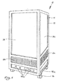
- FIGS. 1 and 2 show the basic structure of an embodiment of a mobile dedusting device 10 according to the invention.
- the dedusting device 10 has a housing 11.
- the housing 11 has a housing frame 12, which consists in the embodiment of an aluminum material.
- a bottom plate 13 is provided, which closes the housing 11 to the outside and is provided in the embodiment with rollers 14 in order to move the dedusting device 10 comfortably.
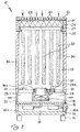
- an underbody 15 is received in the housing frame 12.
- a cavity 16 is formed, in which mechanical and electrical components are included for operation of the dedusting device 10.
- the cavity 16 is closed on all sides by wall elements 16a, wherein a wall element 16a is provided with controls 16b, for example.
- an intermediate bottom 17 is received in the housing frame 12.
- a fan 18 is fixed, which projects into the filter chamber 19 formed above the intermediate bottom 17.
- the fan 18 is sealed by a seal 18a to prevent ambient air outside the fan 18 from flowing into the clean air space 23 (see below).
- the fan 18 is in the embodiment of a centrifugal fan with backward curved blades.
- Such fans are, for example, commercially available as EC centrifugal fans from the series "GreenTech" of the company ebm-pabst Germany.
- a pressure gauge 21 is fixed in the intermediate bottom 17, which is in operative connection with the fan 18 in a conventional manner.
- one or more UV lamps 22 may further be arranged, which evtll to kill. serve germs occurring.
- the pressure gauge 21 is like the fan 18 with a seal 21 a provided.
- the cavity formed by the underbody 15 and the intermediate bottom 17 is designed as a clean air space 23, since the fan 18 transports the cleaned room air through the intermediate bottom 17 into the clean air space 23.
- the clean air space 23 is provided in the exemplary embodiment on three of its sides with a grid 24 through which the purified room air flows into the open air. The clean air space 23 thus acts as an outlet for the purified room air.
- a circumferential support shoulder 25 is provided in the embodiment in the vicinity of the upper end of the housing frame 12.
- the support shoulder 25 is formed integrally with a filter frame 26, which forms the upper part of the housing frame 12.
- the support shoulder 25 serves to support a filter holder 27, which carries a main filter 28.
- the main filter 28 is designed in the embodiment as a fine dust filter of the particle filter class F9, preferably as a pocket filter.
- the particle filter class is of course freely selectable depending on the requirements of the individual case.
- the filter frame 26 also receives a pre-filter 29, which in turn sits in a frame 31 which rests on the filter holder 27.
- the pre-filter 29 is designed in the embodiment as a coarse dust filter of the particle filter class G4.
- the particle filter class (eg G3 to M5) is, of course, freely selectable depending on the requirements of the individual case.
- the filters used correspond in the exemplary embodiment of DIN EN 779: 2012 and DIN EN 1822 according to the provisions of VDI 6022-4.3.9 .. They are particularly water-repellent to prevent microbial contamination.
- Such filters are manufactured, for example, by the German companies HS Gutbau GmbH, Kiel and Kalthoff Gutfilter und Filtermedien GmbH, Selm.
- the pre-filter 29 is covered with a cover grille 32. Since the air-permeable grille extends over the entire cross-section of the housing frame 12, this acts at its upper free end as an inlet opening 33 for the polluted room air.
- the filter chamber 19 is closed by means of housing walls 34 to the outside.
- the housing walls 34 in the exemplary embodiment of aluminum composite plates with a core made of a plastic.
- Such aluminum composite panels are, for example, under the brand "DIBOND ⁇ " of the company 3A Composites GmbH, Singen, commercially available.
- the room air is thus transported over a large area in the vertical direction from top to bottom during the cleaning process, with pipe or hose lines are not needed.
- the cleaned room air is directed radially outward and flows on three sides of the dedusting device 10 (over an angle of 270 degrees) near the ground to the outside.
- the pressure gauge 21 is used to measure the pressure loss in the filter chamber 19, which increases with increasing contamination of the main filter 28. At a defined, preset pressure loss sends the pressure gauge 21 in a conventional manner, a signal to a warning device, which indicates the necessary change of the main filter 28 optically and / or acoustically. The degree of contamination of the pre-filter 29, however, is optically controlled.
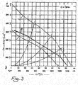
- a radial fan with a backward curved blade which shows the performance characteristics according to line B in FIG. 3 has and reaches a maximum flow rate of 1,400 m 3 / h, is optimally suitable for a mobile dedusting device 10 according to the invention of the following design: External dimensions (L ⁇ W ⁇ H) in cm: 46 ⁇ 46 ⁇ 89 Volume of filter chamber 19: 0.11 m 3 Dimensions of pre-filter 29 (G4, filter cell) in mm: 390 ⁇ 390 ⁇ 47 Dimensions of the main filter 28 (F9, Pocket Feeder) in mm: 390 ⁇ 390 ⁇ 500 Initial filter performance of both filters combined: 1,200 m 3 / h
- the dimensions of the main filter 28 and the filter chamber 19 are dimensioned so that an initial filter performance of 1,200 m 3 air per hour is achieved and an initial pressure drop of 130 Pascal (+/- 20 Pascal) results.
- This starting point corresponds to the point 2 of the line B in FIG. 3 ,
- the fan 18 reaches only 75% to 90% of its rated power and develops a noise level of only 61 to 66 db (A).
- the point 2 on the line B moves to the left, that is, due to the increasing pollution of the main filter 28, the pressure loss increases.
- the power of the fan 18 must be continuously increased.
- the pressure gauge 21 transmits a signal to a warning device to indicate the necessary change of the main filter 28.
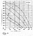
- a radial fan with a backward curved blade which shows the performance characteristics according to line B in FIG. 4 and reaches a maximum flow rate of 3,700 m 3 / h, is optimally suitable for a mobile dedusting device 10 according to the invention of the following design: External dimensions (L ⁇ W ⁇ H) in cm: 66 ⁇ 66 ⁇ 120 Volume of filter chamber 19: 0.29 m 3 Dimensions of pre-filter 29 (G4, filter cell) in mm: 592 ⁇ 592 ⁇ 47 Dimensions of main filter 28 (F9, pocket filter) in mm: 592 ⁇ 592 ⁇ 600 Initial filter performance of both filters combined: 3,000 m 3 / h
- the dimensions of the main filter 28 and the filter chamber 19 are dimensioned so that an initial filter capacity of 3,000 m 3 of air per hour is achieved and an initial pressure loss of 150 Pascal (+/- 20 Pascal) results.
- This starting point corresponds to the point 2 of the line B in FIG. 4 .
- the fan 18 reaches only 75% to 90% of its rated power and develops a noise level of only 63 to 68 db (A).
- the point 2 on the line B moves to the left, that is, due to the increasing contamination of the main filter 28, the pressure loss increases.
- the power of the fan 18 must be continuously increased.
- the pressure gauge 21 transmits a signal to a warning device to indicate the necessary change of the main filter 28.
- this dedusting device 10 With two or more copies of this dedusting device 10 according to the invention, in particular the room air of large rooms can be cleaned efficiently, quietly and energy-saving. With a room size of, for example, 6000m 3 , two of these dedusting devices 10 are much better than a large, in doubt stationary system with an initial filter capacity of 6000m 3 / h.
- a centrifugal fan with a backward curved blade, which shows the performance characteristics according to line A in FIG. 5 has a maximum flow of 700 m 3 / h is optimal suitable for a mobile dedusting device 10 according to the invention of the following design: External dimensions (L ⁇ W ⁇ H) in cm: 34 ⁇ 34 ⁇ 67 Volume of filter chamber 19: 0.042 m 3 Dimensions of pre-filter 29 (G4, filter cell) in mm: 287 ⁇ 287 ⁇ 47 Dimensions of main filter 28 (F9, pocket filter) in mm: 287 ⁇ 287 ⁇ 300 Initial filter performance of both filters combined: 500 m 3 / h
- the dimensions of the main filter 28 and the filter chamber 19 are dimensioned so that an initial filter performance of 500 m 3 air per hour is achieved and an initial pressure drop of 140 Pascal (+/- 20 Pascal) results.
- This starting point corresponds to the point 2 of the line A in FIG. 5 .
- the fan 18 reaches only 75% to 90% of its rated power and develops a noise level of just 59 db (A).
- the point 2 on the line A moves to the left, that is, due to the increasing contamination of the main filter 28, the pressure loss increases.
- the power of the fan 18 must be continuously increased.
- the pressure gauge 21 transmits a signal to a warning device to indicate the necessary change of the main filter 28.
- This small device is particularly well suited for the use of a Schwebstofffilters, eg. A HEPA filter as the main filter.
- This dedusting device 10 according to the invention can also be used as a table device without rollers 14.
Landscapes
- Engineering & Computer Science (AREA)
- Chemical & Material Sciences (AREA)
- Combustion & Propulsion (AREA)
- Mechanical Engineering (AREA)
- General Engineering & Computer Science (AREA)
- Filtering Of Dispersed Particles In Gases (AREA)
Abstract
Die vorliegende Erfindung betrifft eine mobile Entstaubungsvorrichtung (10) zur Reinigung von verschmutzter Raumluft, mit einem Gehäuse (11), in dem mindestens ein Filterelement (28, 29) aufgenommen ist, mit mindestens einem Ventilator (18) zum Ansaugen der verschmutzten Raumluft, mit einer Einlassöffnung (33) für die verschmutzte Raumluft und mit einer Auslassöffnung für gereinigte Raumluft. Erfindungsgemäß ist vorgesehen, dass die Einlassöffnung (33) sich über den gesamten Querschnitt des Gehäuses (11) erstreckt, dass die Auslassöffnung als an mindestens einer Gehäusewand (34) offener Reinluftraum (23) ausgebildet und oberhalb eines Unterbodens (15) des Gehäuses (11) angeordnet ist, dass im Gehäuse (11) oberhalb des Reinluftraums (23) ein Zwischenboden (17) aufgenommen ist, in dem der mindestens eine Ventilator (18) befestigt ist, dass im Gehäuse (11) oberhalb des Zwischenbodens (17) eine Auflageschulter (25) vorgesehen ist, auf der ein mindestens einen Hauptfilter (28) tragender Filterhalter (27) aufliegt, und dass auf dem Filterhalter (27) mindestens ein in einem Rahmen (31) gehaltener Vorfilter (29) aufliegt.The present invention relates to a mobile dedusting device (10) for cleaning soiled room air, comprising a housing (11) in which at least one filter element (28, 29) is accommodated, with at least one fan (18) for drawing in the polluted room air an inlet opening (33) for the polluted room air and with an outlet opening for purified room air. According to the invention, the inlet opening (33) extends over the entire cross section of the housing (11), the outlet opening being designed as a clean air space (23) open at at least one housing wall (34) and above a lower floor (15) of the housing (11 ) is arranged, that in the housing (11) above the clean air space (23) an intermediate bottom (17) is received, in which the at least one fan (18) is fixed, that in the housing (11) above the intermediate bottom (17) has a support shoulder (25) is provided, on which a at least one main filter (28) carrying the filter holder (27) rests, and in that on the filter holder (27) at least one in a frame (31) held pre-filter (29) rests.
Description
Die vorliegende Erfindung betrifft eine mobile Entstaubungsvorrichtung zur Reinigung von verschmutzter Raumluft, mit einem Gehäuse, in dem mindestens ein Filterelement aufgenommen ist, mit mindestens einem Ventilator zum Ansaugen der verschmutzten Raumluft, mit einer Einlassöffnung für die verschmutzte Raumluft und mit einer Auslassöffnung für gereinigte Raumluft.The present invention relates to a mobile dedusting device for cleaning polluted room air, comprising a housing in which at least one filter element is received, with at least one fan for sucking the polluted room air, with an inlet opening for the polluted room air and with an outlet opening for purified room air.
Eine gattungsgemäße mobile Entstaubungsvorrichtung ist aus der deutschen Gebrauchsmusterschrift
Die Aufgabe der vorliegenden Erfindung besteht darin, eine gattungsgemäße Entstaubungsvorrichtung derart weiterzubilden, dass sie bei einfachem, kompaktem Aufbau und geringem Energieverbrauch möglichst effizient arbeitet.The object of the present invention is to develop a generic dedusting device such that it works as efficiently as possible with a simple, compact design and low energy consumption.
Die Lösung besteht in einer mobilen Entstaubungsvorrichtung mit den Merkmalen des Patentanspruchs 1. Erfindungsgemäß ist vorgesehen, dass die Einlassöffnung sich über den qesamten Querschnitt des Gehäuses erstreckt, dass die Auslassöffnung als an mindestens einer Gehäusewand offener Reinluftraum ausgebildet und oberhalb eines Unterbodens des Gehäuses angeordnet ist, dass im Gehäuse oberhalb des Reinluftraums ein Zwischenboden aufgenommen ist, in dem der mindestens eine Ventilator befestigt ist, dass im Gehäuse oberhalb des Zwischenbodens eine Auflageschulter vorgesehen ist, auf der ein mindestens einen Hauptfilter tragender Filterhalter aufliegt, und dass auf dem Filterhalter mindestens ein in einem Rahmen gehaltener Vorfilter aufliegt.The solution consists in a mobile dedusting device with the features of claim 1. According to the invention, the inlet opening extends over the qesamten cross-section of the housing, that the outlet opening is formed as at least one housing wall open clean air space and disposed above a lower floor of the housing, that in the housing above the clean air space an intermediate bottom is received, in which the at least one fan is mounted, that in the housing above the false floor a support shoulder is provided, on which rests at least one main filter filter holder, and that on the filter holder at least one in a Frame held pre-filter rests.
Der wesentliche Vorteil der erfindungsgemäßen Entstaubungsvorrichtung besteht darin, dass keine Rohr- oder Schlauchleitungen für den Transport der Raumluft vorgesehen sind, entlang derer Druckverluste auftreten können. Vielmehr wird die verschmutzte Raumluft über den gesamten Querschnitt des Gehäuses der erfindungsgemäßen Entstaubungsvorrichtung (das heißt, über die gesamte nach außen gerichtete Oberfläche des Vorfilters) angesaugt, und die gereinigte Raumluft wird in Bodennähe in radialer Richtung nach außen abgegeben, wobei der Reinluftraum als Auslass für die gereinigte Raumluft wirkt. Die einzigen Druckverluste beim Betrieb der erfindungsgemäßen Entstaubungsvorrichtung werden im Wesentlichen vom Hauptfilter verursacht.The main advantage of the dedusting device according to the invention is that no pipe or hose lines are provided for the transport of the room air, along which pressure losses can occur. Rather, the polluted room air over the entire cross-section of the housing of the dedusting device according to the invention (that is, over the entire outwardly facing surface of the prefilter) sucked, and the purified room air is delivered near the ground in the radial direction to the outside, the clean air space as an outlet for the purified room air is effective. The only pressure losses during operation of the dedusting device according to the invention are essentially caused by the main filter.
Diese erfindungsgemäße konstruktive Maßnahme hat zur Folge, dass der "Anlagenkennpunkt", d.h. der optimale Betriebspunkt der erfindungsgemäßen mobilen Entstaubungsvorrichtung nicht von derartigen, von Rohr- oder Schlauchleitungen verursachten Druckverlusten negativ beeinflusst wird. Vielmehr entspricht bei der erfindungsgemäßen Entstaubungsvorrichtung der "Anlagenkennpunkt" vollständig der Kennkurve des verwendeten Ventilators.This constructive measure according to the invention has the consequence that the "system characteristic point", i. the optimum operating point of the mobile dedusting device according to the invention is not adversely affected by such, caused by pipe or hose lines pressure losses. Rather, in the dedusting device according to the invention, the "system characteristic point" corresponds completely to the characteristic curve of the fan used.
Dies bedeutet, dass die erfindungsgemäße Entstaubungsvorrichtung bei minimalem Stromverbrauch besonders effizient und geräuscharm arbeitet.This means that the dedusting device according to the invention operates with minimum power consumption particularly efficient and quiet.
Da die gereinigte, vergleichsweise warme Raumluft in Bodennähe aus der erfindungsgemäßen Entstaubungsvorrichtung ausströmt, trägt sie zumindest im Ausströmbereich zu einer verbesserten Wärmeverteilung der Raumluft insgesamt bei.Since the cleaned, comparatively warm room air flows out of the dedusting device according to the invention near the bottom, it contributes at least in the discharge area to an improved heat distribution of the room air as a whole.
Vorteilhafte Weiterbildungen ergeben sich aus den Unteransprüchen.Advantageous developments emerge from the subclaims.
Zweckmäßigerweise ist unterhalb des Unterbodens ein durch eine Bodenplatte abgeschlossener Hohlraum zur Aufnahme mechanischer und elektrischer Komponenten zum Betrieb der Entstaubungsvorrichtung ausgebildet, so dass für die erfindungsgemäße Entstaubungsvorrichtung eine besonders kompakte Bauweise verwirklicht werden kann.Conveniently, a cavity enclosed by a bottom plate cavity for receiving mechanical and electrical components for operating the dedusting device is formed below the subfloor, so that for the dedusting device according to the invention a particularly compact design can be realized.
Vorteilhafterweise ist oberhalb des Zwischenbodens ein mit dem Ventilator in Wirkverbindung stehendes Druckmessgerät vorgesehen um bei von einem verstopften Filter verursachten übermäßigem Druckverlust einen rechtzeitigen Filterwechsel zu signalisieren.Advantageously, a pressure measuring device operatively connected to the fan is provided above the intermediate bottom in order to signal a timely filter change in the event of an excessive pressure loss caused by a clogged filter.
Vorzugsweise ist der Ventilator als Radialventilator mit rückwärts gekrümmten Schaufeln ausgebildet. Derartige Ventilatoren haben sich als besonders leistungsfähig und für die erfindungsgemäße Entstaubungsvorrichtung als hervorragend geeignet erwiesen.Preferably, the fan is designed as a radial fan with backward curved blades. Such fans have proven to be particularly efficient and for the deduster according to the invention as outstandingly suitable.
Als Hauptfilter wird vorzugsweise ein Feinstaubfilter und/oder Schwebstofffilter verwendet, abhängig von der Qualität der zu reinigenden Raumluft. Der Vorfilter ist zweckmäßigerweise ein Grobstaubfilter.The main filter used is preferably a fine dust filter and / or particle filter, depending on the quality of the room air to be cleaned. The pre-filter is expediently a coarse dust filter.
Eine weitere vorteilhafte Weiterbildung sieht vor, dass unterhalb des Hauptfilters eine Vorrichtung zur Abgabe von UV-Strahlung vorgesehen ist, um einer eventuellen Verkeimung der Filter vorzubeugen.A further advantageous embodiment provides that a device for emitting UV radiation is provided below the main filter in order to prevent any possible contamination of the filter.
Vorzugsweise wird die Effizienz der erfindungsgemäßen Entstaubungsvorrichtung in der Weise optimiert, dass die gesamte Entstaubungsvorrichtung gemäß den Eigenschaften des verwendeten Ventilators dimensioniert ist. Es ist erwünscht, dass mindestens ein 1:1-Raumluftaustausch erfolgt, d.h. innerhalb einer Stunde wird die komplette Raumluft eines Raumes ausgetauscht.Preferably, the efficiency of the dedusting device according to the invention is optimized in such a way that the entire dedusting device is dimensioned according to the characteristics of the fan used. It is desirable that at least one 1: 1 room air exchange occur, i. Within one hour, the entire room air of a room is exchanged.
Die Filterelemente mit Filterfläche sowie die Gehäusemaße sind letztlich an der Kennkurve des Ventilators ausgerichtet. Die Filterfläche bzw. das Filtervolumen frisch eingesetzter Hauptfilter sind so ausgelegt, dass bei beim Betrieb des Ventilators mit 75% bis 90% seiner maximalen Leistung ein durch den Hauptfilter bestimmter Druckverlust erzeugt wird. Dieser Druckverlust entspricht auf der Kennkurve des Ventilators dem herstellerseitig definierten ersten Betriebspunkt des Ventilators. Die Filterfläche bzw. das Filtervolumen des Hauptfilter ist so ausgelegt, dass dieser Betriebspunkt eine addierte Filterleistung von Hauptfilter und Vorfilter in Kubikmeter Raumluft je Stunde definiert, die unter dem möglichen maximalen Durchsatz der Filter für die Raumluft liegt. Bei dieser Auslegung wird bei einem niedrigeren Druckverlust eine höhere Abscheideleistung als bisher bekannt erzeugt, wobei der Energieverbrauch der erfindungsgemäßen Entstaubungsvorrichtung deutlich reduziert ist. Der gewünschte Druckaufbau erfolgt somit bei minimalem Stromverbrauch und zugleich mit minimaler Geräuschentwicklung in db(A).The filter elements with filter surface and the housing dimensions are ultimately aligned with the characteristic curve of the fan. The filter area or the filter volume of freshly inserted main filter are designed so that during operation of the fan with 75% to 90% of its maximum power, a pressure loss determined by the main filter is generated. This pressure loss corresponds to the characteristic curve of the fan to the manufacturer defined first operating point of the fan. The filter area or the filter volume of the main filter is designed so that this operating point defines an added filter capacity of the main filter and pre-filter in cubic meters of room air per hour, which is below the possible maximum throughput of the filters for the room air is. In this design, a higher separation efficiency is generated than previously known at a lower pressure loss, the energy consumption of the dedusting device according to the invention is significantly reduced. The desired pressure build-up thus takes place with minimal power consumption and at the same time with minimal noise in db (A).
Ein weiterer Vorteil besteht darin, dass eine ggf. vorhandene Warnanzeige zum Wechsel des Hauptfilters anhand der Kennkurve des Ventilators eingestellt werden kann. Je stärker der Filter verschmutzt ist, desto weiter wandern die Kenndaten des Ventilators auf seiner Kennkurve in Richtung höherer Druckverluste. Anhand einer im Gehäuse vorgesehenen Druckmessvorrichtung kann der Druckverlust, bei dem ein Filterwechsel erfolgen sollte, genau gemessen werden. Bei Erreichen des anhand der Kennkurve des Ventilators voreingestellten Druckverlusts wird die Warnanzeige aktiviert.Another advantage is that a possibly existing warning display for changing the main filter based on the characteristic curve of the fan can be set. The more the filter is contaminated, the further the characteristic data of the fan travel on its characteristic curve in the direction of higher pressure losses. Based on a pressure measuring device provided in the housing, the pressure loss at which a filter change should take place can be measured accurately. When the pressure loss preset on the basis of the characteristic curve of the fan is reached, the warning display is activated.
Ein zusätzlicher Vorteil der erfindungsgemäß betriebenen Entstaubungsvorrichtung besteht darin, dass sie wesentlich kompakter gebaut werden kann als im Stand der Technik bekannt. Dies ist sowohl aufgrund der Effizienz, mit der die erfindungsgemäße Entstaubungsvorrichtung arbeitet, als auch aufgrund der einfachen Bauweise ohne Rohr- oder Schlauchleitungen möglich.An additional advantage of the de-dusting device operated according to the invention is that it can be built much more compact than known in the prior art. This is possible both due to the efficiency with which the dedusting device according to the invention works, as well as due to the simple design without pipe or hose lines.
Im Ergebnis wird eine erfindungsgemäße mobile Entstaubungsvorrichtung erhalten, die effizient, geräuscharm und energiesparend arbeitet. Die erfindungsgemäße Entstaubungsvorrichtung ermöglicht ferner eine flexible Anwendung beim Kunden, der aufgrund der hohen Effektivität je nach Raumgröße zwei oder mehrere erfindungsgemäße mobile Entstaubungsvorrichtungen kombinieren kann. Dies ist in der Regel wesentlich günstiger als die Bereitstellung eines einzigen Großgeräts.As a result, a mobile dedusting apparatus according to the invention is obtained, which operates efficiently, quietly and energy-saving. The dedusting device according to the invention also allows flexible use by the customer, who can combine two or more mobile dedusting devices according to the invention, depending on the size of the room, due to the high degree of effectiveness. This is usually much cheaper than providing a single large appliance.
Ausführungsbeispiele der Erfindung werden im Folgenden anhand der beigefügten Zeichnungen näher erläutert. Es zeigen in einer schematischen, nicht maßstabsgetreuen Darstellung:
- Figur 1
- ein Ausführungsbeispiel des Aufbaus einer erfindungsgemäßen mobilen Entstaubungsvorrichtung in einer perspektivischen Darstellung;
- Figur 2
- das Ausführungsbeispiel gemäß
Figur 1 im Schnitt; Figur 3- Leistungskenndaten eines Ventilators für ein erstes Ausführungsbeispiel einer erfindungsgemäßen mobilen Entstaubungsvorrichtung in der Bauweise gemäßen den
Figuren 1 und2 ; - Figur 4
- Leistungskenndaten eines Ventilators für ein weiteres Ausführungsbeispiel einer erfindungsgemäßen mobilen Entstaubungsvorrichtung in der Bauweise gemäßen den
Figuren 1 und2 ; - Figur 5
- Leistungskenndaten eines Ventilators für ein weiteres Ausführungsbeispiel einer erfindungsgemäßen mobilen Entstaubungsvorrichtung in der Bauweise gemäßen den
Figuren 1 und2 .
- FIG. 1
- an embodiment of the construction of a mobile dedusting device according to the invention in a perspective view;
- FIG. 2
- the embodiment according to
FIG. 1 on average; - FIG. 3
- Performance characteristics of a fan for a first embodiment of a mobile dedusting device according to the invention in the construction according to the
FIGS. 1 and2 ; - FIG. 4
- Performance characteristics of a fan for a further embodiment of a mobile dedusting device according to the invention in the construction according to the
FIGS. 1 and2 ; - FIG. 5
- Performance characteristics of a fan for a further embodiment of a mobile dedusting device according to the invention in the construction according to the
FIGS. 1 and2 ,
Die
Oberhalb des Unterbodens 15 und beabstandet zu diesem ist ein Zwischenboden 17 in den Gehäuserahmen 12 aufgenommen. Im Zwischenboden 17 ist ein Ventilator 18 befestigt, der in den über dem Zwischenboden 17 gebildeten Filterraum 19 hineinragt. Der Ventilator 18 ist mittels einer Dichtung 18a abgedichtet, um zu verhindern, dass Raumluft außerhalb des Ventilators 18 in den Reinluftraum 23 (siehe unten) strömt. Der Ventilator 18 ist im Ausführungsbeispiel ein Radialventilator mit rückwärts gekrümmten Schaufeln. Derartige Ventilatoren sind bspw. als EC-Radialventilatoren aus der Serie "GreenTech" des Unternehmens ebm-pabst Deutschland im Handel zu erwerben.Above the
Ferner ist im Zwischenboden 17 ein Druckmessgerät 21 befestigt, welches mit dem Ventilator 18 in an sich bekannter Weise in Wirkverbindung steht. Auf dem Zwischenboden 17 können ferner ein oder mehrere UV-Strahler 22 angeordnet sein, welche zur Abtötung evtll. auftretender Keime dienen. Das Druckmessgerät 21 ist wie der Ventilator 18 mit einer Abdichtung 21 a versehen.Further, a
Der von dem Unterboden 15 und dem Zwischenboden 17 gebildete Hohlraum ist als Reinluftraum 23 ausgebildet, da der Ventilator 18 die gereinigte Raumluft durch den Zwischenboden 17 hindurch in den Reinluftraum 23 transportiert. Der Reinluftraum 23 ist im Ausführungsbeispiel auf drei seiner Seiten mit einem Gitter 24 versehen, durch welches die gereinigte Raumluft ins Freie strömt. Der Reinluftraum 23 wirkt also als Auslass für die gereinigte Raumluft.The cavity formed by the
Im Filterraum 19 ist im Ausführungsbeispiel in der Nähe des oberen Endes des Gehäuserahmens 12 eine umlaufende Auflageschulter 25 vorgesehen. Im Ausführungsbeispiel ist die Auflageschulter 25 einstückig mit einem Filterrahmen 26 ausgebildet, der den oberen Teil des Gehäuserahmens 12 bildet. Die Auflageschulter 25 dient zur Auflage eines Filterhalters 27, der einen Hauptfilter 28 trägt. Der Hauptfilter 28 ist im Ausführungsbeispiel als Feinstaubfilter der Partikelfilterklasse F9 ausgelegt, vorzugsweise als Taschenfilter. Die Partikelfilterklasse ist je nach den Anforderungen des Einzelfalls selbstverständlich frei wählbar.In the
Der Filterrahmen 26 nimmt ferner einen Vorfilter 29 auf, der seinerseits in einem Rahmen 31 sitzt, welcher auf dem Filterhalter 27 aufliegt. Der Vorfilter 29 ist im Ausführungsbeispiel als Grobstaubfilter der Partikelfilterklasse G4 ausgelegt. Die Partikelfilterklasse (bspw. G3 bis M5) ist je nach den Anforderungen des Einzelfalls selbstverständlich frei wählbar.The
Die verwendeten Filter entsprechen im Ausführungsbeispiel der DIN EN 779:2012 bzw. der DIN EN 1822 gemäß den Vorschriften des VDI 6022-4.3.9.. Sie sind insbesondere wasserabweisend, um eine Verkeimung zu vermeiden. Derartige Filter werden bspw. von den deutschen Unternehmen HS Luftfilterbau GmbH, Kiel und Kalthoff Luftfilter und Filtermedien GmbH, Selm, hergestellt.The filters used correspond in the exemplary embodiment of DIN EN 779: 2012 and DIN EN 1822 according to the provisions of VDI 6022-4.3.9 .. They are particularly water-repellent to prevent microbial contamination. Such filters are manufactured, for example, by the German companies HS Luftfilterbau GmbH, Kiel and Kalthoff Luftfilter und Filtermedien GmbH, Selm.
Der Vorfilter 29 ist mit einem Abdeckgitter 32 bedeckt. Da das luftdurchlässige Abdeckgitter sich über den gesamten Querschnitt des Gehäuserahmens 12 erstreckt, wirkt dieser an seinem oberen freien Ende als Einlassöffnung 33 für die verschmutzte Raumluft.The pre-filter 29 is covered with a
Der Filterraum 19 ist mittels Gehäusewänden 34 nach außen abgeschlossen. Die Gehäusewände 34 bestehen im Ausführungsbeispiel aus Aluminiumverbundplatten mit einem Kern aus einem Kunststoff. Derartige Aluminiumverbundplatten sind bspw. unter der Marke "DIBOND©" des Unternehmens 3A Composites GmbH, Singen, im Handel erhältlich.The
Die erfindungsgemäße Entstaubungsvorrichtung 10 arbeitet wie folgt:
Der Ventilator 18 saugt im Betriebdurch das Abdeckgitter 32 und dieEinlassöffnung 33, d.h. über den gesamten Querschnitt des Gehäuses 11, verschmutzte Raumluft an. Die Raumluft tritt durchden Vorfilter 29 und wird dabei im Ausführungsbeispiel von groben Verunreinigungen (Partikelgröße über 10 µm) befreit. Anschließend strömt die Raumluftdurch den Hauptfilter 28, wo sie von Feinstaub bzw. Schwebstoffen (Partikelgröße im Ausführungsbeispiel zwischen 0,4 µm und 1 µm) befreit wird. Die gereinigte Raumluft tritt durchden Ventilator 18 inden Reinluftraum 23 ein und strömt durch dieGitter 24 ins Freie.
- The
fan 18 sucks in operation through thecover grille 32 and theinlet opening 33, ie over the entire cross section of thehousing 11, soiled room air. The room air passes through the pre-filter 29 and is freed in the embodiment of coarse impurities (particle size above 10 microns). Subsequently, the room air flows through themain filter 28, where it is freed of fine dust or suspended matter (particle size in the embodiment between 0.4 .mu.m and 1 .mu.m). The cleaned room air enters through thefan 18 in theclean air space 23 and flows through thegrid 24 into the open.
Die Raumluft wird somit während des Reinigungsprozesses großflächig in vertikaler Richtung von oben nach unten transportiert, wobei Rohr- oder Schlauchleitungen nicht benötigt werden. Vor dem Austreten aus der Entstaubungsvorrichtung 10 wird die gereinigte Raumluft radial nach außen geleitet und strömt auf drei Seiten der Entstaubungsvorrichtung 10 (über einen Winkel von 270 Winkelgrad) in Bodennähe ins Freie.The room air is thus transported over a large area in the vertical direction from top to bottom during the cleaning process, with pipe or hose lines are not needed. Before exiting the
Der Druckmesser 21 dient zur Messung des Druckverlusts im Filterraum 19, der mit zunehmender Verschmutzung des Hauptfilters 28 ansteigt. Bei einem definierten, voreingestellten Druckverlust sendet der Druckmesser 21 in an sich bekannter Weise ein Signal an eine Warneinrichtung, die optisch und/oder akustisch auf den notwendigen Wechsel des Hauptfilters 28 hinweist. Der Verschmutzungsgrad des Vorfilters 29 wird hingegen optisch kontrolliert.The
Im Folgenden werden drei Ausführungsbeispiele für drei erfindungsgemäße Auslegungen der erfindungsgemäßen Entstaubungsvorrichtung 10 beschrieben. Diese drei Ausführungsbeispiele weisen den soeben beschriebenen Aufbau und die soeben beschriebene Funktionsweise auf. Daher wird für diese drei Ausführungsbeispiele auf die
Ein Radialventilator mit rückwärts gekrümmten Schaufel, der die Leistungskenndaten gemäß Linie B in
Die Maße des Hauptfilter 28 und des Filterraums 19 sind so bemessen, dass eine Anfangs-Filterleistung von 1.200 m3 Luft pro Stunde erzielt wird sowie ein Anfangsdruckverlust von 130 Pascal (+/- 20 Pascal) resultiert. Dieser Startpunkt entspricht dem Punkt 2 der Linie B in
Bei dieser Auslegung wird bei einem niedrigeren Druckverlust eine höhere Abscheideleistung als bisher bekannt erzeugt, wobei der Energieverbrauch der erfindungsgemäßen Entstaubungsvorrichtung deutlich reduziert ist. Der gewünschte Druckaufbau erfolgt somit bei minimalem Stromverbrauch und zugleich mit minimaler Geräuschentwicklung in db(A).In this design, a higher separation efficiency is generated than previously known at a lower pressure loss, the energy consumption of the dedusting device according to the invention is significantly reduced. The desired pressure build-up thus takes place with minimal power consumption and at the same time with minimal noise in db (A).
Ein Radialventilator mit rückwärts gekrümmten Schaufel, der die Leistungskenndaten gemäß Linie B in
Die Maße des Hauptfilter 28 und des Filterraums 19 sind so bemessen, dass eine Anfangs-Filterleistung von 3.000 m3 Luft pro Stunde erzielt wird sowie ein Anfangsdruckverlust von 150 Pascal (+/- 20 Pascal) resultiert. Dieser Startpunkt entspricht dem Punkt 2 der Linie B in
Bei dieser Auslegung wird bei einem niedrigeren Druckverlust eine höhere Abscheideleistung als bisher bekannt erzeugt, wobei der Energieverbrauch der erfindungsgemäßen Entstaubungsvorrichtung deutlich reduziert ist. Der gewünschte Druckaufbau erfolgt somit bei minimalem Stromverbrauch und zugleich mit minimaler Geräuschentwicklung in db(A).In this design, a higher separation efficiency is generated than previously known at a lower pressure loss, the energy consumption of the dedusting device according to the invention is significantly reduced. The desired pressure build-up thus takes place with minimal power consumption and at the same time with minimal noise in db (A).
Mit zwei oder mehr Exemplaren dieser erfindungsgemäßen Entstaubungsvorrichtung 10 kann insbesondere die Raumluft großer Räume effizient, leise und energiesparend gereinigt werden. Bei einer Raumgröße von bspw. 6000m3 eignen sich zwei dieser Entstaubungsvorrichtungen 10 wesentlich besser als eine große, im Zweifel stationäre Anlage mit einer Anfangs-Filterleistung von 6000m3/h.With two or more copies of this
Ein Radialventilator mit rückwärts gekrümmten Schaufel, der die Leistungskenndaten gemäß Linie A in
Die Maße des Hauptfilters 28 und des Filterraums 19 sind so bemessen, dass eine Anfangs-Filterleistung von 500 m3 Luft pro Stunde erzielt wird sowie ein Anfangsdruckverlust von 140 Pascal (+/- 20 Pascal) resultiert. Dieser Startpunkt entspricht dem Punkt 2 der Linie A in
Bei dieser Auslegung wird bei einem niedrigeren Druckverlust eine höhere Abscheideleistung als bisher bekannt erzeugt, wobei der Energieverbrauch der erfindungsgemäßen Entstaubungsvorrichtung deutlich reduziert ist. Der gewünschte Druckaufbau erfolgt somit bei minimalem Stromverbrauch und zugleich mit minimaler Geräuschentwicklung in db(A).In this design, a higher separation efficiency is generated than previously known at a lower pressure loss, the energy consumption of the dedusting device according to the invention is significantly reduced. The desired pressure build-up thus takes place with minimal power consumption and at the same time with minimal noise in db (A).
Dieses Kleingerät ist besonders gut für die Verwendung eines Schwebstofffilters, bspw. eines HEPA-Filters als Hauptfilter geeignet. Diese erfindungsgemäße Entstaubungsvorrichtung 10 kann auch als Tischgerät ohne Rollen 14 verwendet werden.This small device is particularly well suited for the use of a Schwebstofffilters, eg. A HEPA filter as the main filter. This
Claims (10)
Applications Claiming Priority (1)
| Application Number | Priority Date | Filing Date | Title |
|---|---|---|---|
| DE102015010979.0A DE102015010979A1 (en) | 2015-08-26 | 2015-08-26 | Mobile dedusting device |
Publications (1)
| Publication Number | Publication Date |
|---|---|
| EP3136012A1 true EP3136012A1 (en) | 2017-03-01 |
Family
ID=56800224
Family Applications (1)
| Application Number | Title | Priority Date | Filing Date |
|---|---|---|---|
| EP16185651.3A Withdrawn EP3136012A1 (en) | 2015-08-26 | 2016-08-25 | Mobile dedusting device |
Country Status (2)
| Country | Link |
|---|---|
| EP (1) | EP3136012A1 (en) |
| DE (1) | DE102015010979A1 (en) |
Cited By (3)
| Publication number | Priority date | Publication date | Assignee | Title |
|---|---|---|---|---|
| CN108548244A (en) * | 2018-04-12 | 2018-09-18 | 徐波 | Novel automatic control dust-collecting air purifier |
| GB2597827A (en) * | 2020-06-08 | 2022-02-09 | Spark Product Creation Ltd | Air-conditioner |
| US11708986B1 (en) * | 2022-07-12 | 2023-07-25 | Intellytic Ventures Ltd | Smart IoT energy saving sound wave air filter system and use for air purifiers and a method of air filtration thereof |
Families Citing this family (1)
| Publication number | Priority date | Publication date | Assignee | Title |
|---|---|---|---|---|
| DE102019112992A1 (en) * | 2019-05-16 | 2020-11-19 | Keller Lufttechnik Gmbh + Co. Kg | Filter unit |
Citations (3)
| Publication number | Priority date | Publication date | Assignee | Title |
|---|---|---|---|---|
| DE9206851U1 (en) | 1992-05-21 | 1992-08-06 | BHSU Luft- und Umwelttechnik GmbH, 3418 Uslar | Mobile dust extractor |
| US20100058927A1 (en) * | 2006-07-14 | 2010-03-11 | Freshman Ab | Air filter arrangement and a method for manufacturing the same |
| US20140238243A1 (en) * | 2013-02-27 | 2014-08-28 | Kip Jardine | Apparatus for filtering air |
Family Cites Families (3)
| Publication number | Priority date | Publication date | Assignee | Title |
|---|---|---|---|---|
| US5399319A (en) * | 1993-08-02 | 1995-03-21 | Vector Technologies Ltd. | Apparatus for filtering air and for creating a positive/negative pressure |
| US7531141B2 (en) * | 2006-10-12 | 2009-05-12 | Airinspace B.V. | Mobile air decontamination and purification unit |
| DE102009053505A1 (en) * | 2009-11-16 | 2011-05-19 | Wu, Fu-Chi, Northridge | Air cleaner, has fan controlled to pass outside air to air outlet such that low pressure is produced around space below housing and high pressure is produced around space above housing, so that convection of air takes place |
-
2015
- 2015-08-26 DE DE102015010979.0A patent/DE102015010979A1/en not_active Withdrawn
-
2016
- 2016-08-25 EP EP16185651.3A patent/EP3136012A1/en not_active Withdrawn
Patent Citations (3)
| Publication number | Priority date | Publication date | Assignee | Title |
|---|---|---|---|---|
| DE9206851U1 (en) | 1992-05-21 | 1992-08-06 | BHSU Luft- und Umwelttechnik GmbH, 3418 Uslar | Mobile dust extractor |
| US20100058927A1 (en) * | 2006-07-14 | 2010-03-11 | Freshman Ab | Air filter arrangement and a method for manufacturing the same |
| US20140238243A1 (en) * | 2013-02-27 | 2014-08-28 | Kip Jardine | Apparatus for filtering air |
Cited By (4)
| Publication number | Priority date | Publication date | Assignee | Title |
|---|---|---|---|---|
| CN108548244A (en) * | 2018-04-12 | 2018-09-18 | 徐波 | Novel automatic control dust-collecting air purifier |
| CN108548244B (en) * | 2018-04-12 | 2020-06-16 | 谢飞鹏 | Automatic control dust removal air purification device |
| GB2597827A (en) * | 2020-06-08 | 2022-02-09 | Spark Product Creation Ltd | Air-conditioner |
| US11708986B1 (en) * | 2022-07-12 | 2023-07-25 | Intellytic Ventures Ltd | Smart IoT energy saving sound wave air filter system and use for air purifiers and a method of air filtration thereof |
Also Published As
| Publication number | Publication date |
|---|---|
| DE102015010979A1 (en) | 2017-03-02 |
Similar Documents
| Publication | Publication Date | Title |
|---|---|---|
| DE102013110631B4 (en) | Device for cleaning the room air | |
| EP3136012A1 (en) | Mobile dedusting device | |
| CH708655A1 (en) | Air purifier with ozone and particulate matter cleaning. | |
| EP0839538A2 (en) | Air purifying apparatus | |
| DE60130105T2 (en) | METHOD AND DEVICE FOR AIR FILTRATION | |
| DE102005020400A1 (en) | Device for filtering extremely fine dust | |
| DE102015005865B4 (en) | Apparatus for drying insulating layers of floors in a vacuum process | |
| DE202016105466U1 (en) | Multilayered ionizing dedusting combined fresh air air cleaning system | |
| WO1991010392A1 (en) | Vacuum cleaner | |
| DE202020105240U1 (en) | Air purification device for filtering room air | |
| DE1604296C3 (en) | Ventilation system | |
| DE202020106913U1 (en) | Air cleaning device for cleaning room air | |
| EP2790742B1 (en) | Indoor air purification apparatus with plasma generator and radial exhaust | |
| EP2645009A2 (en) | Ventilation system | |
| DE3719734A1 (en) | Filter unit | |
| DE202021101555U1 (en) | Device for filtering air | |
| EP2181583A2 (en) | Device and method for venting or removing air | |
| DE20018765U1 (en) | Mobile laminar box (laminar flow system) | |
| DE202015102781U1 (en) | Ventilation system for clean rooms | |
| EP3984566B1 (en) | Hygiene light | |
| EP2375180A2 (en) | Dehumidifying device | |
| DE19750276A1 (en) | Filter for domestic chimneys | |
| DE19601486A1 (en) | Air conditioner for breathing air in work environment | |
| DE102015108698A1 (en) | Air purifier for cleaning room air and fresh air | |
| DE102018130602A1 (en) | Air purification device |
Legal Events
| Date | Code | Title | Description |
|---|---|---|---|
| PUAI | Public reference made under article 153(3) epc to a published international application that has entered the european phase |
Free format text: ORIGINAL CODE: 0009012 |
|
| STAA | Information on the status of an ep patent application or granted ep patent |
Free format text: STATUS: THE APPLICATION HAS BEEN PUBLISHED |
|
| AK | Designated contracting states |
Kind code of ref document: A1 Designated state(s): AL AT BE BG CH CY CZ DE DK EE ES FI FR GB GR HR HU IE IS IT LI LT LU LV MC MK MT NL NO PL PT RO RS SE SI SK SM TR |
|
| AX | Request for extension of the european patent |
Extension state: BA ME |
|
| STAA | Information on the status of an ep patent application or granted ep patent |
Free format text: STATUS: REQUEST FOR EXAMINATION WAS MADE |
|
| 17P | Request for examination filed |
Effective date: 20170831 |
|
| RBV | Designated contracting states (corrected) |
Designated state(s): AL AT BE BG CH CY CZ DE DK EE ES FI FR GB GR HR HU IE IS IT LI LT LU LV MC MK MT NL NO PL PT RO RS SE SI SK SM TR |
|
| STAA | Information on the status of an ep patent application or granted ep patent |
Free format text: STATUS: EXAMINATION IS IN PROGRESS |
|
| 17Q | First examination report despatched |
Effective date: 20200710 |
|
| STAA | Information on the status of an ep patent application or granted ep patent |
Free format text: STATUS: EXAMINATION IS IN PROGRESS |
|
| STAA | Information on the status of an ep patent application or granted ep patent |
Free format text: STATUS: THE APPLICATION IS DEEMED TO BE WITHDRAWN |
|
| 18D | Application deemed to be withdrawn |
Effective date: 20240301 |