EP3135897B1 - Kraftstoffzufuhrvorrichtung und kraftstoffrücklaufnutzungspuffergefäss - Google Patents
Kraftstoffzufuhrvorrichtung und kraftstoffrücklaufnutzungspuffergefäss Download PDFInfo
- Publication number
- EP3135897B1 EP3135897B1 EP16169755.2A EP16169755A EP3135897B1 EP 3135897 B1 EP3135897 B1 EP 3135897B1 EP 16169755 A EP16169755 A EP 16169755A EP 3135897 B1 EP3135897 B1 EP 3135897B1
- Authority
- EP
- European Patent Office
- Prior art keywords
- fuel
- port
- hole
- return
- outlet port
- Prior art date
- Legal status (The legal status is an assumption and is not a legal conclusion. Google has not performed a legal analysis and makes no representation as to the accuracy of the status listed.)
- Not-in-force
Links
- 239000000446 fuel Substances 0.000 title claims description 186
- 238000004891 communication Methods 0.000 claims description 21
- 239000012528 membrane Substances 0.000 claims description 15
- 238000009423 ventilation Methods 0.000 claims description 14
- 238000011084 recovery Methods 0.000 claims description 13
- 239000007788 liquid Substances 0.000 claims description 12
- 230000008878 coupling Effects 0.000 claims description 6
- 238000010168 coupling process Methods 0.000 claims description 6
- 238000005859 coupling reaction Methods 0.000 claims description 6
- 230000014759 maintenance of location Effects 0.000 claims description 6
- 230000002265 prevention Effects 0.000 claims description 5
- 230000000717 retained effect Effects 0.000 claims description 2
- 238000007789 sealing Methods 0.000 claims description 2
- 239000002828 fuel tank Substances 0.000 description 6
- 238000002347 injection Methods 0.000 description 4
- 239000007924 injection Substances 0.000 description 4
- 238000000034 method Methods 0.000 description 4
- 241000282414 Homo sapiens Species 0.000 description 3
- 230000007613 environmental effect Effects 0.000 description 3
- 238000003915 air pollution Methods 0.000 description 2
- 238000002485 combustion reaction Methods 0.000 description 2
- 238000001514 detection method Methods 0.000 description 2
- 238000002156 mixing Methods 0.000 description 2
- 230000008569 process Effects 0.000 description 2
- 230000009467 reduction Effects 0.000 description 2
- 238000000889 atomisation Methods 0.000 description 1
- 230000006835 compression Effects 0.000 description 1
- 238000007906 compression Methods 0.000 description 1
- 239000002283 diesel fuel Substances 0.000 description 1
- 238000005265 energy consumption Methods 0.000 description 1
- 238000005516 engineering process Methods 0.000 description 1
- 230000006872 improvement Effects 0.000 description 1
- 230000013011 mating Effects 0.000 description 1
- 239000002184 metal Substances 0.000 description 1
- 238000004064 recycling Methods 0.000 description 1
- 239000000243 solution Substances 0.000 description 1
- 238000009834 vaporization Methods 0.000 description 1
- 230000008016 vaporization Effects 0.000 description 1
- 239000002699 waste material Substances 0.000 description 1
Images


Classifications
-
- F—MECHANICAL ENGINEERING; LIGHTING; HEATING; WEAPONS; BLASTING
- F02—COMBUSTION ENGINES; HOT-GAS OR COMBUSTION-PRODUCT ENGINE PLANTS
- F02M—SUPPLYING COMBUSTION ENGINES IN GENERAL WITH COMBUSTIBLE MIXTURES OR CONSTITUENTS THEREOF
- F02M37/00—Apparatus or systems for feeding liquid fuel from storage containers to carburettors or fuel-injection apparatus; Arrangements for purifying liquid fuel specially adapted for, or arranged on, internal-combustion engines
- F02M37/0047—Layout or arrangement of systems for feeding fuel
- F02M37/0052—Details on the fuel return circuit; Arrangement of pressure regulators
-
- F—MECHANICAL ENGINEERING; LIGHTING; HEATING; WEAPONS; BLASTING
- F02—COMBUSTION ENGINES; HOT-GAS OR COMBUSTION-PRODUCT ENGINE PLANTS
- F02M—SUPPLYING COMBUSTION ENGINES IN GENERAL WITH COMBUSTIBLE MIXTURES OR CONSTITUENTS THEREOF
- F02M33/00—Other apparatus for treating combustion-air, fuel or fuel-air mixture
- F02M33/02—Other apparatus for treating combustion-air, fuel or fuel-air mixture for collecting and returning condensed fuel
-
- F—MECHANICAL ENGINEERING; LIGHTING; HEATING; WEAPONS; BLASTING
- F02—COMBUSTION ENGINES; HOT-GAS OR COMBUSTION-PRODUCT ENGINE PLANTS
- F02M—SUPPLYING COMBUSTION ENGINES IN GENERAL WITH COMBUSTIBLE MIXTURES OR CONSTITUENTS THEREOF
- F02M37/00—Apparatus or systems for feeding liquid fuel from storage containers to carburettors or fuel-injection apparatus; Arrangements for purifying liquid fuel specially adapted for, or arranged on, internal-combustion engines
- F02M37/0011—Constructional details; Manufacturing or assembly of elements of fuel systems; Materials therefor
- F02M37/0023—Valves in the fuel supply and return system
-
- F—MECHANICAL ENGINEERING; LIGHTING; HEATING; WEAPONS; BLASTING
- F02—COMBUSTION ENGINES; HOT-GAS OR COMBUSTION-PRODUCT ENGINE PLANTS
- F02M—SUPPLYING COMBUSTION ENGINES IN GENERAL WITH COMBUSTIBLE MIXTURES OR CONSTITUENTS THEREOF
- F02M37/00—Apparatus or systems for feeding liquid fuel from storage containers to carburettors or fuel-injection apparatus; Arrangements for purifying liquid fuel specially adapted for, or arranged on, internal-combustion engines
- F02M37/0011—Constructional details; Manufacturing or assembly of elements of fuel systems; Materials therefor
- F02M37/0017—Constructional details; Manufacturing or assembly of elements of fuel systems; Materials therefor related to fuel pipes or their connections, e.g. joints or sealings
-
- F—MECHANICAL ENGINEERING; LIGHTING; HEATING; WEAPONS; BLASTING
- F02—COMBUSTION ENGINES; HOT-GAS OR COMBUSTION-PRODUCT ENGINE PLANTS
- F02M—SUPPLYING COMBUSTION ENGINES IN GENERAL WITH COMBUSTIBLE MIXTURES OR CONSTITUENTS THEREOF
- F02M37/00—Apparatus or systems for feeding liquid fuel from storage containers to carburettors or fuel-injection apparatus; Arrangements for purifying liquid fuel specially adapted for, or arranged on, internal-combustion engines
- F02M37/22—Arrangements for purifying liquid fuel specially adapted for, or arranged on, internal-combustion engines, e.g. arrangements in the feeding system
- F02M37/32—Arrangements for purifying liquid fuel specially adapted for, or arranged on, internal-combustion engines, e.g. arrangements in the feeding system characterised by filters or filter arrangements
Definitions
- the present invention relates generally to an automobile accessory, and more particularly to a fuel supply device and a return fuel utilization buffer jar.
- Patent document GB 1 433 875 A discloses a recirculatory liquid supply system that comprise a main storage reservoir from which fuel is supplied to an engine and a subsidiary storage reservoir that receives recirculated fuel from the engine and comprises a shut-off valve controlled by a float.
- the subsidiary storage reservoir comprises a vent pipe through which air is allowed to enter or leave the subsidiary storage reservoir.
- Patent document US 4 205 643 A disclose a device for supplying fuel to an internal combustion engine in which an intermediate chamber is connected to a recovery chamber having an opening extending into a carburetor and the intermediate chamber comprises a cylindrical chamber in which a perforated cylinder is mounted and a float having a base of a conical shape is movably received in the cylinder.
- the intermediate chamber is connected via a return duct to the carburetor.
- Patent document US 4 502 450 A discloses a diesel fuel control valve and system in which a mixing valve is connected between a fuel tank and a diesel engine.
- the mixing valve comprises a chamber in which a buoyant member is received and comprises a closure element that partly located in a port to close the port unless there is a sufficient volume of fuel in the chamber to cause the buoyant member rise in the chamber. Fuel flowing through the port is allowed to mix with fuel supplied from the fuel tank to get into the engine.
- an object of the present invention is to provide a fuel supply device and a return fuel utilization buffer jar, which enable effective use of high temperature fuel returning from an engine to achieve the purposes of saving energy and increasing engine operation efficiency.
- the present invention provides a fuel supply device, which supplies fuel necessary for an operation of a rotary high-pressure fuel distribution engine.
- the fuel supply device comprises a first three-way valve, a second three-way valve, and a return fuel utilization buffer jar.
- the return fuel utilization buffer jar comprises a hollow jar portion and a buoy arranged in interior of the hollow jar portion.
- the hollow jar portion has a lower portion in which a return fuel inlet port and a return fuel outlet port in communication with the interior are formed.
- the hollow jar portion has an upper portion in which a fuel vapor recovery hole in communication with the interior is formed.
- the return fuel inlet port functions to conduct in return fuel from the rotary high-pressure fuel distribution engine and vapor of the return fuel vapor is conducted out, through the fuel vapor recovery hole.
- the first three-way valve comprises a fuel inlet port, a fuel outlet port, and a return fuel receiving port.
- a reversal flow prevention device is arranged between the fuel inlet port and the fuel outlet port that constrains fuel to flow, in one direction, from the fuel inlet port to the fuel outlet port.
- the fuel outlet port and the return fuel receiving port are connected to and in communication with each other.
- the return fuel in the hollow jar portion flowing through the return fuel outlet port is conducted through the return fuel receiving port of the first three-way valve to the rotary high-pressure fuel distribution engine.
- the second three-way valve comprises a gas inlet port, a gas outlet port, and a ventilation port.
- a one-way reversal flow prevention device is arranged between the ventilation port and the gas inlet port that constrains flow in one direction from the ventilation port to the gas inlet port.
- the gas inlet port and the gas outlet port are connected to and in communication with each other.
- the vapor of the return fuel vapor that is conducted out through the fuel vapor recovery hole is conducted through the gas inlet port of the second three-way valve.
- the return fuel utilization buffer jar comprises a connection rod.
- the connection rod has an end that is in a conical form.
- the hollow jar portion comprises a jar body, an upper cap, a lower cap, and a guide post.
- the upper cap is coupled to and closes the jar body and comprises an upper shaft hole and the fuel vapor recovery hole formed therein.
- the lower cap is mounted to the lower end of the jar body and comprises the return fuel inlet port and a post hole formed therein.
- the guide post is retained in a post hole and comprises a central hole and the return fuel outlet port formed therein.
- the central hole has a lower end that is located in the return fuel outlet port and is in a conical form such that when the connection rod is set up in the upper shaft hole and the central hole, upward/downward movement the buoy selectively opens/closes the passage that is established between the return fuel outlet port and the lower end of the central hole.
- each of the upper cap and the lower cap comprises an O-ring for sealing against the hollow jar portion and preventing leakage of fuel.
- the upper cap and the lower cap comprise a transparent fuel tube connected therebetween for observation of the liquid level in the hollow jar portion.
- the lower cap is provided with a temperature sensor coupling seat mounted thereto for coupling with a temperature sensor, such that the temperature sensor so coupled may detect a fuel temperature of return fuel in the return fuel utilization buffer jar.
- the first three-way valve of the fuel supply device comprises a holed seat and a valve seat.
- the holed seat comprises a holed seat junction surface, a holed seat external surface, and a holed seat lateral surface.
- the fuel outlet port is formed and arranged on the holed seat lateral surface.
- the return fuel receiving port is formed and arranged on the holed seat external surface.
- the holed seat junction surface comprises a passage trough formed therein and connected between and in communication with the return fuel receiving port and the fuel outlet por.
- the valve seat comprises a valve seat junction surface, a valve seat external surface, and a valve seat lateral surface.
- the fuel inlet port is formed and arranged on the valve seat external surface.
- the valve seat junction surface comprises a circling groove formed therein and corresponding to a circumference of the passage trough, a threaded hole formed inboard the circling groove, and a valve hole in communication with the fuel inlet port.
- the circling groove receives an O-ring disposed therein.
- the threaded hole receives a membrane spring, which selectively covers and closes the valve hole, and a retention board, which limits an opening angle of the membrane spring, to be sequentially fixed thereto.
- the second three-way valve of the fuel supply device comprises a holed seat and a valve seat.
- the holed seat comprises a holed seat junction surface, a holed seat external surface, and a holed seat lateral surface.
- the gas inlet port is formed and arranged on the holed seat lateral surface.
- the gas outlet port is formed and arranged on the holed seat external surface.
- the holed seat junction surface comprises a passage trough formed therein and connected between and in communication with the gas inlet port and the gas outlet port.
- the valve seat comprises a valve seat junction surface, a valve seat external surface, and a valve seat lateral surface.
- the ventilation port is formed and arranged on the valve seat external surface.
- the valve seat junction surface comprises a circling groove formed therein and corresponding to a circumference of the passage trough, a threaded hole formed inboard the circling groove, and a valve hole in communication with the ventilation port.
- the circling groove comprises an O-ring disposed therein.
- the threaded hole receives a membrane spring, which selectively covers and closes the valve hole, and a retention board, which limits an opening angle of the membrane spring, to be sequentially fixed thereto.
- the present invention provides a fuel supply device and a return fuel utilization buffer jar thereof, which allows high temperature fuel collected and recovered from an engine to be directly re-supplied to the engine for recycling and reuse so as to prevent waste resulting from vaporization during the process of recovery of the high temperature fuel thereby achieving the purposes of saving energy and improving engine operation efficiency.
- the fuel supply device 10 comprises three-way valves 11, 12 and a return fuel utilization buffer jar 13, which is applicable to supplying fuel necessary for an operation of a rotary high-pressure fuel distribution engine 40.
- fuel contained in a fuel tank 20 is first filtered by a fuel filter 30 and is then supplied to an injection pump of the rotary high-pressure fuel distribution engine 40 to be pressurized by the injection pump for distributing and feeding to injection nozzles of the rotary high-pressure fuel distribution engine 40 for atomization and combustion to generate power.
- an injection pump of the rotary high-pressure fuel distribution engine 40 to be pressurized by the injection pump for distributing and feeding to injection nozzles of the rotary high-pressure fuel distribution engine 40 for atomization and combustion to generate power.
- excessive fuel is returned to the fuel tank 20 as return fuel.
- the return fuel which has been pressurized, generally has a fuel temperature that is higher than a fuel temperature of the fuel supplied from the fuel tank 20.
- the fuel temperature of the return fuel is often between 72 to 75 degrees Celsius and may exhibit a phenomenon of being vaporized, making it inadequate to be directly fed into and used by the rotary high-pressure fuel distribution engine 40.
- the present invention provides the fuel supply device 10 that is arranged between the fuel tank 20 and the rotary high-pressure fuel distribution engine 40 in order to effectively collect and recover the return fuel for re-use for achieving the purposes of saving energy and improving engine operation efficiency.
- the three-way valve 11 comprises a holed seat 110 and a valve seat 120.
- the holed seat 110 comprises a holed seat junction surface 1101, a holed seat lateral surface, and a holed seat external surface 1103.
- a fuel outlet port 112 is formed and arranged on the holed seat lateral surface.
- a return fuel receiving port 113 is formed and arranged on the holed seat external surface 1103.
- the holed seat junction surface 1101 comprises a passage trough 1104 formed therein and connected between and communicating with the return fuel receiving port 113 and the fuel outlet port 112.
- the valve seat 120 comprises a valve seat external surface 1201, a valve seat lateral surface 1202, and a valve seat junction surface 1203.
- a fuel inlet port 111 is formed and arranged on the valve seat external surface 1201.
- the valve seat junction surface 1203 comprises a circling groove 1204 formed therein to correspond to an outer circumference of the passage trough 1104, a threaded hole 1205 that is formed inboard the circling groove 1204, and a valve hole 1206 in communication with the fuel inlet port 111.
- the circling groove 1204 receives an O-ring 1207 disposed therein.
- Fixed, in sequence, to the threaded hole 1205 by a screw 1200 are a retention board 1209 that limits an opening angle of a membrane spring 1208 and the membrane spring 1208 that selectively covers and closes the valve hole 1206.
- the three-way valve 11 comprises the fuel inlet port 111, the fuel outlet port 112, and the return fuel receiving port 113.
- the membrane spring 1208 that selectively covers and closes the valve hole 1206 provides a function of a check valve to limit fuel to be fed uni-directionally from the fuel inlet port 111 to the fuel outlet port 112.
- the fuel outlet port 112 and the return fuel receiving port 113 are connected and in communication with each other by through the passage trough 1104.
- the membrane spring 1208 is a temperature-resistant metal film and is preferably capable of resisting negative suction pressure of 0.05-0.1Pa and also resisting positive suction pressure of 2-5 Pa so as to exhibit properties of low resistance, reversal prevention, and large flow rate.
- the three-way valve 12 comprises a holed seat 110 and a valve seat 120.
- the holed seat 110 comprises a holed seat junction surface 1101, a holed seat lateral surface, and a holed seat external surface 1103.
- An gas inlet port 122 is formed and arranged on the holed seat lateral surface.
- a gas outlet port 123 is formed and arranged on the holed seat external surface 1103.
- the holed seat junction surface 1101 comprises a passage trough 1104 formed therein and connected between and communicating with the gas inlet port 122 and the gas outlet port 123.
- the valve seat 120 comprises a valve seat junction surface 1203, a valve seat external surface 1201, and a valve seat lateral surface 1202.
- a ventilation port 121 is formed and arranged on the valve seat external surface 1201.
- the valve seat junction surface 1203 comprises a circling groove 1204 formed therein to correspond to an outer circumference of the passage trough 1104, a threaded hole 1205 that is formed in board the circling groove 1204, and a valve hole 1206 in communication with the ventilation port 121.
- the circling groove 1204 receives an O-ring 1207 disposed therein.
- Fixed, in sequence, to the threaded hole 1205 by a screw 1210 are a retention board 1209 that limits an opening angle of a membrane spring 1208 and the membrane spring 1208 that selectively covers and closes the valve hole 1206.
- the three-way valve 12 comprises the gas inlet port 122, the gas outlet port 123, and the ventilation port 121.
- the membrane spring 1208 that selectively covers and closes the valve hole 1206 provides a function of a one-way check valve constraining flow in one direction from the ventilation port 121 to the gas inlet port 12 in order to regulate fuel vapor pressure in the return fuel utilization buffer jar 13.
- the gas inlet port 122 and the gas outlet port 123 are connected to and in communication with each other through the passage trough 1104.
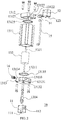
- the return fuel utilization buffer jar 13 comprises a hollow jar portion 131 and a buoy 132 arranged in the hollow jar portion 131.
- the buoy 132 comprises a connection rod 1321.
- the connection rod 1321 has an end 13211 that is in a conical form.
- the hollow jar portion 131 comprises a jar body 1311, an upper cap 1312, a lower cap 1313, and a guide post 1314.
- the upper cap 1312 is hermetically coupled, through an O-ring 13125, to the jar body 1311 and comprises an upper shaft hole 13121, a fuel vapor recovery hole 13122, and an upper liquid level hole 13123 formed therein.
- the fuel vapor recovery hole 13122 and the upper liquid level hole 13123 are arranged to provide communication between inside and outside of the hollow jar portion 131 in order to conduct the vapor of return fuel contained inside the hollow jar portion 131 from the fuel vapor recovery hole 13122, through a double-end-threaded adaptor 14, to the gas inlet port 122 of the three-way valve 12.
- the lower cap 1313 is hermetically coupled, through an O-ring 13135, to a bottom of the jar body 1311 and comprises a return fuel inlet port 13131, a post hole 13132, a lower liquid level hole 13133, and a seat hole 13134 formed therein for communication between the inside and outside of the hollow jar portion 131 in order to conduct return fuel from the rotary high-pressure fuel distribution engine 40 into the hollow jar portion 131.
- a transparent fuel tube 15 is connected between the upper liquid level hole 13123 and the lower liquid level hole 13133 for observation and recognition of liquid level inside the hollow jar portion 131.
- the seat hole 13134 is provided with a temperature sensor coupling seat 16 mounted thereto for coupling with a temperature sensor for temperature detection when detection of the fuel temperature of the return fuel inside the return fuel utilization buffer jar 13 is desired.
- the guide post 1314 is fixed, in a hermetical manner, to and received in the post hole 13132 of the lower cap 1313 and comprises a central hole 13141 and a return fuel outlet port 13142 formed therein.
- the central hole 13141 has a lower end 13143 that is located in the return fuel outlet port 13142 and is in a conical form for mating the conical end 13211 of the connection rod 1321 of the buoy 132 when the connection rod 1321 is set up in the upper shaft hole 13121 and the central hole 13141, so that a passage may be selectively established or blocked between the return fuel outlet port 13142 and the lower end 13143 of the central hole 13141 by means of upward/downward movement of the buoy 132.
- the buoy 132 when the liquid level of the return fuel received in the hollow jar portion 13 is higher than a threshold level, the buoy 132 is moved by buoyance to open the passage. In this condition, the return fuel inside the hollow jar portion 13 is allowed to flow through the return fuel outlet port 13142 of the guide post 1314 to the conical lower end 13143 of the central hole 13141 to further flow from the return fuel receiving port 113 of the three-way valve 11, via the fuel outlet port 112, into the rotary high-pressure fuel distribution engine 40 for recovery and re-use.
Landscapes
- Engineering & Computer Science (AREA)
- Chemical & Material Sciences (AREA)
- Combustion & Propulsion (AREA)
- Mechanical Engineering (AREA)
- General Engineering & Computer Science (AREA)
- Cooling, Air Intake And Gas Exhaust, And Fuel Tank Arrangements In Propulsion Units (AREA)
- Fuel-Injection Apparatus (AREA)
- Check Valves (AREA)
Claims (7)
- Eine Kraftstoffzufuhrvorrichtung, die Kraftstoff für den Betrieb eines Dreh-Hochdruck-Kraftstoffverteilungsmotors liefert, mit:einem Kraftstoffrücklaufnutzungs-Puffergefäß (13), das ein hohles Gefäßteil (131) und einen Schwimmkörper (132) im Innern des hohlen Gefäßteils (131) umfasst, wobei das hohle Gefäßteil (131) einen unteren Teil umfasst, in dem eine Kraftstoffrücklauf-Einlassöffnung (13131) und eine Kraftstoffrücklauf-Auslassöffnung (13142) in Verbindung mit dem Innern gebildet sind, wobei das hohle Gefäßteil (131) einen oberen Teil umfasst, in dem ein Kraftstoffdampf-Rückgewinnungsloch (13122) in Verbindung mit dem Innern gebildet ist,wobei die Kraftstoffrücklauf-Einlassöffnung (13131) Rücklaufkraftstoff von dem Dreh-Hochdruck-Kraftstoffverteilungsmotor einleitet und Dampf des Rücklaufkraftstoffdampfes hinausgeleitet wird, durch das Kraftstoffdampf-Rückgewinnungsloch (13122) hindurch, und wobei, wenn ein Flüssigkeitsstand des Kraftstoffrücklaufs in dem hohlen Gefäßteil (131) höher ist als eine Schwellenhöhe, der Schwimmkörper (132) vom Auftrieb bewegt wird, um einen Durchgang zu öffnen, damit der Rücklaufkraftstoff in dem hohlen Gefäßteil (131) durch die Kraftstoffrücklauf-Auslassöffnung (13142) fließt; gekennzeichnet dadurch, dassein erstes Dreiwegeventil (11) eine Kraftstoffeinlassöffnung (111), eine Kraftstoffauslassöffnung (112) und eine Kraftstoffrücklauf-Empfangsöffhung (113) umfasst, wobei eine Umkehrströmungsverhinderungs-Vorrichtung zwischen der Kraftstoffeinlassöffnung (111) und der Kraftstoffauslassöffnung (112) angeordnet ist, die den Kraftstoff zwingt, in einer Richtung, von der Kraftstoffeinlassöffnung (111) zur Kraftstoffauslassöffnung (112) zu strömen,die Kraftstoffauslassöffnung (112) und die Kraftstoffrücklauf-Empfangsöffnung (113) sind miteinander verbunden, wobei der Kraftstoffrücklauf in dem hohlen Gefäßteil (131), der durch die Kraftstoffrücklauf-Auslassöffnung (13142) fließt, durch die Kraftstoffrücklauf-Empfangsöffnung (113) des ersten Dreiwegeventils (11) hindurch zu dem Dreh-Hochdruck-Kraftstoffverteilungsmotor geführt wird; undein zweites Dreiwegeventil (12) umfasst eine Gaseinlassöffnung (122), eine Gasauslassöffnung (123), und eine Belüftungsöffnung (121), wobei eine Einweg-Umkehrströmungsverhinderungs-Vorrichtung zwischen der Belüftungsöffnung (121) und der Gaseinlassöffnung (122) angeordnet ist.
- Die Kraftstoffzufuhrvorrichtung nach Anspruch 1, wobei der Schwimmkörper (132) einen Verbindungsstab (1321) umfasst, dessen eines Ende konische Form hat, wobei das hohle Gefäßteil (131) folgendes umfasst:einen Gefäßkörper (1311),eine obere Kappe (1312), die mit dem Gefäßkörper (1311) verbunden ist und ihn verschließt und ein oberes Schaftloch (13121) und das darin gebildete Kraftstoffdampf-Rückgewinnungsloch (13122) umfasst;eine untere Kappe (1313), die an das untere Ende des Gefäßkörpers (1311) montiert ist und die Kraftstoffrücklauf-Einlassöffnung (13131) und ein darin gebildetes Pfostenloch (13132) umfasst; undeinen Führungspfosten (1314), der in einem Pfostenloch (13132) gehalten wird und ein mittleres Loch (13141) und die darin gebildete Kraftstoffrücklauf-Auslassöffnung (13142) umfasst, das mittlere Loch (13141) umfasst ein unteres Ende, das sich in der Kraftstoffrücklauf-Auslassöffnung (13142) befindet und von konischer Form ist, so dass, wenn der Verbindungsstab (1321) in dem oberen Schaftloch (13121) und dem mittleren Loch (13141) aufgebaut wird, die Bewegung des Schwimmkörpers (132) nach oben/nach unten den Durchgang zwischen der Kraftstoffrücklauf-Auslassöffnung (13142) und dem unteren Ende des mittleren Loches (13141) wahlweise öffnet/schließt.
- Die Kraftstoffzufuhrvorrichtung nach Anspruch 2, wobei sowohl die obere Kappe (1312) als auch die untere Kappe (1313) einen Dichtungsring (13125, 13135) zur Abdichtung gegen das hohle Gefäßteil (131) umfasst.
- Die Kraftstoffzufuhrvorrichtung nach Anspruch 2, wobei die obere Kappe (1312) und die untere Kappe (1313) ein transparentes Kraftstoffrohr (15) umfassen, das dazwischen zur Beobachtung des Flüssigkeitsstandes in dem hohlen Gefäßteil (131) angeschlossen ist.
- Die Kraftstoffzufuhrvorrichtung nach Anspruch 2, wobei die untere Kappe (1313) einen Temperatursensorkuppelsitz (16) aufweist, der daran montiert ist, zur Kupplung mit einem Temperatursensor.
- Die Kraftstoffzufuhrvorrichtung nach Anspruch 1, wobei das erste Dreiwegeventil (11) folgendes umfasst:eine durchlochte Aufnahme (110), die eine Verbindungsoberfläche für die durchlochte Aufnahme (1101) umfasst, eine Außenfläche für die durchlochte Aufnahme (1103) und eine Seitenfläche für die durchlochte Aufnahme, wobei die Kraftstoffauslassöffnung (112) auf der Seitenfläche für die durchlochte Aufnahme gebildet und angeordnet ist,die Kraftstoffrücklauf-Empfangsöffnung (113) ist auf der durchlochten Aufnahmeaußenfläche (1103) gebildet und angeordnet, die durchlochte Aufnahmeverbindungs-Oberfläche (1101) umfasst einen Durchgangstrog (1104), der darin gebildet und mit der Kraftstoffrücklauf-Empfangsöffnung (113) und der Kraftstoffauslassöffnung (112) verbunden ist; undeinen Ventilsitz (120), der eine Ventilsitzverbindungsfläche (1203), eine Ventilsitzaußenfläche (1201) und eine Ventilsitzseitenfläche (1202) umfasst, die Kraftstoffeinlassöffnung (111) ist auf der Ventilsitzaußenfläche (1201) gebildet und angeordnet, die Ventilsitzverbindungsfläche (1203) umfasst eine kreisförmige Nut (1204), die darin gebildet ist und einem Umfang des Durchgangstrogs (1104) entspricht, ein Gewindeloch (1205) in der kreisförmigen Nut (1204), und ein Ventilloch (1206), das in Verbindung mit der Kraftstoffeinlassöffnung (111) steht, die kreisförmige Nut (1204) nimmt einen Dichtungsring (1207) auf, der darin angeordnet ist, das Gewindeloch (1205) nimmt eine Membranfeder (1208) auf, die wahlweise das Ventilloch (1206) bedeckt und schließt, und eine Rückhaltetafel (1209), die einen Öffnungswinkel der Membranfeder (1208) begrenzt, zur folgenden Befestigung daran.
- Die Kraftstoffzufuhrvorrichtung nach Anspruch 1, wobei das zweite Dreiwegeventil (12) folgendes umfasst:eine durchlochte Aufnahme (110), die eine Verbindungsfläche für die durchlochte Aufnahme (1101) umfasst, eine Außenfläche (1103) für die durchlochte Aufnahme und eine Seitenfläche für die durchlochte Aufnahme, wobei die Gaseinlassöffnung (122) auf der Seitenfläche für die durchlochte Aufnahme gebildet und angeordnet ist,die Gasauslassöffnung (123) ist auf der Außenfläche für die durchlochte Aufnahme (1103) gebildet und angeordnet, die Verbindungsfläche für die durchlochte Aufnahme (1101) umfasst einen Durchgangstrog (1104), der darin gebildet und mit der Gaseinlassöffnung (122) und der Gasauslassöffnung (123) verbunden ist; undeinen Ventilsitz (120), der eine Ventilsitzverbindungsfläche (1203), eine Ventilsitzaußenfläche (1201) und eine Ventilsitzseitenfläche (1202) umfasst, wobei die Belüftungsöffnung (121) auf der Ventilsitzaußenfläche (1201) gebildet und angeordnet ist,Die Ventilsitzverbindungsfläche (1203) umfasst eine kreisförmige Nut (1204), die darin gebildet ist und einem Umfang des Durchgangstrogs (1104) entspricht, ein Gewindeloch (1205) in der kreisförmigen Nut (1204) und ein Ventilloch (1206), das in Verbindung mit der Belüftungsöffnung (121) steht,
die kreisförmige Nut (1204) umfasst einen Dichtungsring (1207), der darin angeordnet ist, das Gewindeloch (1205) nimmt eine Membranfeder (1208) auf, die selektiv das Ventilloch (1206) bedeckt und schließt, und eine Rückhaltetafel (1209), die einen Öffnungswinkel der Membranfeder (1208) begrenzt, um danach daran befestigt zu sein.
Applications Claiming Priority (1)
| Application Number | Priority Date | Filing Date | Title |
|---|---|---|---|
| TW104213956U TWM514516U (zh) | 2015-08-28 | 2015-08-28 | 燃油供給裝置及其中之回油利用緩衝瓶 |
Publications (2)
| Publication Number | Publication Date |
|---|---|
| EP3135897A1 EP3135897A1 (de) | 2017-03-01 |
| EP3135897B1 true EP3135897B1 (de) | 2018-04-11 |
Family
ID=55409450
Family Applications (1)
| Application Number | Title | Priority Date | Filing Date |
|---|---|---|---|
| EP16169755.2A Not-in-force EP3135897B1 (de) | 2015-08-28 | 2016-05-16 | Kraftstoffzufuhrvorrichtung und kraftstoffrücklaufnutzungspuffergefäss |
Country Status (5)
| Country | Link |
|---|---|
| US (1) | US9945336B2 (de) |
| EP (1) | EP3135897B1 (de) |
| JP (1) | JP3205535U (de) |
| CN (1) | CN205503320U (de) |
| TW (1) | TWM514516U (de) |
Families Citing this family (1)
| Publication number | Priority date | Publication date | Assignee | Title |
|---|---|---|---|---|
| ES2988511T3 (es) * | 2019-04-04 | 2024-11-20 | Optos Plc | Predicción de una condición patológica a partir de una imagen médica |
Family Cites Families (10)
| Publication number | Priority date | Publication date | Assignee | Title |
|---|---|---|---|---|
| GB1433875A (en) * | 1972-08-18 | 1976-04-28 | Bishop B L H | Liquid supply and measuring systems |
| US4205643A (en) * | 1975-12-01 | 1980-06-03 | Societe Anonyme Pour L'equipement Electrique Des Vehicules S.E.V. Marchal | Device for supplying fuel to an internal combustion engine |
| US4502450A (en) * | 1979-07-13 | 1985-03-05 | Standard-Thomson Corporation | Diesel fuel control valve and system |
| JPS59165854A (ja) * | 1983-03-09 | 1984-09-19 | Aisan Ind Co Ltd | 燃料蒸発損失防止装置 |
| US5471964A (en) * | 1993-12-30 | 1995-12-05 | Hurner; Erwin E. | Apparatus and process for blending and treating fuel |
| GB2327979A (en) * | 1997-08-01 | 1999-02-10 | Ford Global Tech Inc | I.c. engine fuel vapour extraction system |
| BE1012697A3 (fr) * | 1999-06-01 | 2001-02-06 | Solvay | Reservoir a carburant. |
| US7188610B2 (en) * | 2002-06-21 | 2007-03-13 | Ti Group Automotive Systems, L.L.C. | No-return loop fuel system |
| TW200636156A (en) * | 2005-03-25 | 2006-10-16 | Mikuni Kogyo Kk | A fuel injection device for the combustion circulation tank and fuel circulation system |
| US7281525B2 (en) * | 2006-02-27 | 2007-10-16 | Briggs & Stratton Corporation | Filter canister family |
-
2015
- 2015-08-28 TW TW104213956U patent/TWM514516U/zh not_active IP Right Cessation
-
2016
- 2016-04-14 CN CN201620312337.0U patent/CN205503320U/zh not_active Expired - Fee Related
- 2016-05-16 EP EP16169755.2A patent/EP3135897B1/de not_active Not-in-force
- 2016-05-16 US US15/155,080 patent/US9945336B2/en active Active
- 2016-05-19 JP JP2016002299U patent/JP3205535U/ja not_active Expired - Fee Related
Non-Patent Citations (1)
| Title |
|---|
| None * |
Also Published As
| Publication number | Publication date |
|---|---|
| CN205503320U (zh) | 2016-08-24 |
| EP3135897A1 (de) | 2017-03-01 |
| US20170058848A1 (en) | 2017-03-02 |
| TWM514516U (zh) | 2015-12-21 |
| JP3205535U (ja) | 2016-07-28 |
| US9945336B2 (en) | 2018-04-17 |
Similar Documents
| Publication | Publication Date | Title |
|---|---|---|
| KR101610464B1 (ko) | 유체 분리용 세퍼레이터 및 이를 이용한 scr 요소수 주입 시스템 | |
| WO2007091079A8 (en) | Device for preventing full introduction of a first conduit into a second conduit | |
| WO2006067586A3 (en) | Controlling vapor emission in a small engine fuel tank system | |
| WO2010048504A3 (en) | Vapor vent control apparatus, system and outboard marine engine therewith | |
| CN107840301A (zh) | 无压自封油气回收加油枪 | |
| CN203754406U (zh) | 油气回收自封加油枪 | |
| EP3135897B1 (de) | Kraftstoffzufuhrvorrichtung und kraftstoffrücklaufnutzungspuffergefäss | |
| CN209159416U (zh) | 用于汽车油箱上的可以精确调节关闭高度的内置式组合阀 | |
| WO2016033924A1 (zh) | 一种带有碳罐的空滤器总成 | |
| CN203023148U (zh) | 集成有泄压阀的喷射泵喷嘴 | |
| CN206570023U (zh) | 轻型环保油气回收自封加油枪 | |
| CN105922862B (zh) | 一种用于马鞍形油箱的车载油气回收装置及方法 | |
| CA2365831A1 (en) | Quick-close tank vent control system | |
| CN103663339B (zh) | 油气回收自封加油枪 | |
| US20150136091A1 (en) | Jet pump of fuel pump module for vehicle | |
| CN201170148Y (zh) | 电控燃油喷射发动机的燃油箱 | |
| CN201560872U (zh) | 低油位供油电动燃油泵总成 | |
| WO2017059929A1 (en) | A fuel tank arrangement for a dual fuel internal combustion engine | |
| CN201739044U (zh) | 一种汽车发动机辅助进气装置 | |
| CN204399483U (zh) | 一种无人机供油系统 | |
| CN210460898U (zh) | 一种高压燃气喷射控制驱动阀、燃气喷射系统及发动机 | |
| CN202209243U (zh) | 压力调节器 | |
| CN203702410U (zh) | 一种柴油发电机油箱的出油结构 | |
| CN207145108U (zh) | 油气分离器、供油系统以及车辆 | |
| US20120006839A1 (en) | Fuel tank vent system |
Legal Events
| Date | Code | Title | Description |
|---|---|---|---|
| PUAI | Public reference made under article 153(3) epc to a published international application that has entered the european phase |
Free format text: ORIGINAL CODE: 0009012 |
|
| STAA | Information on the status of an ep patent application or granted ep patent |
Free format text: STATUS: REQUEST FOR EXAMINATION WAS MADE |
|
| 17P | Request for examination filed |
Effective date: 20160516 |
|
| AK | Designated contracting states |
Kind code of ref document: A1 Designated state(s): AL AT BE BG CH CY CZ DE DK EE ES FI FR GB GR HR HU IE IS IT LI LT LU LV MC MK MT NL NO PL PT RO RS SE SI SK SM TR |
|
| AX | Request for extension of the european patent |
Extension state: BA ME |
|
| GRAP | Despatch of communication of intention to grant a patent |
Free format text: ORIGINAL CODE: EPIDOSNIGR1 |
|
| STAA | Information on the status of an ep patent application or granted ep patent |
Free format text: STATUS: GRANT OF PATENT IS INTENDED |
|
| RIC1 | Information provided on ipc code assigned before grant |
Ipc: B60K 15/03 20060101ALN20171027BHEP Ipc: B60K 15/035 20060101ALN20171027BHEP Ipc: F02M 37/00 20060101AFI20171027BHEP Ipc: F16K 11/08 20060101ALI20171027BHEP Ipc: F02M 33/02 20060101ALI20171027BHEP Ipc: F02M 37/22 20060101ALI20171027BHEP Ipc: F02M 33/00 20060101ALI20171027BHEP |
|
| INTG | Intention to grant announced |
Effective date: 20171205 |
|
| GRAS | Grant fee paid |
Free format text: ORIGINAL CODE: EPIDOSNIGR3 |
|
| GRAA | (expected) grant |
Free format text: ORIGINAL CODE: 0009210 |
|
| STAA | Information on the status of an ep patent application or granted ep patent |
Free format text: STATUS: THE PATENT HAS BEEN GRANTED |
|
| AK | Designated contracting states |
Kind code of ref document: B1 Designated state(s): AL AT BE BG CH CY CZ DE DK EE ES FI FR GB GR HR HU IE IS IT LI LT LU LV MC MK MT NL NO PL PT RO RS SE SI SK SM TR |
|
| REG | Reference to a national code |
Ref country code: GB Ref legal event code: FG4D |
|
| REG | Reference to a national code |
Ref country code: CH Ref legal event code: EP |
|
| REG | Reference to a national code |
Ref country code: AT Ref legal event code: REF Ref document number: 988300 Country of ref document: AT Kind code of ref document: T Effective date: 20180415 |
|
| REG | Reference to a national code |
Ref country code: IE Ref legal event code: FG4D |
|
| REG | Reference to a national code |
Ref country code: DE Ref legal event code: R096 Ref document number: 602016002316 Country of ref document: DE |
|
| REG | Reference to a national code |
Ref country code: FR Ref legal event code: PLFP Year of fee payment: 3 |
|
| REG | Reference to a national code |
Ref country code: NL Ref legal event code: MP Effective date: 20180411 |
|
| REG | Reference to a national code |
Ref country code: LT Ref legal event code: MG4D |
|
| PG25 | Lapsed in a contracting state [announced via postgrant information from national office to epo] |
Ref country code: NL Free format text: LAPSE BECAUSE OF FAILURE TO SUBMIT A TRANSLATION OF THE DESCRIPTION OR TO PAY THE FEE WITHIN THE PRESCRIBED TIME-LIMIT Effective date: 20180411 |
|
| PG25 | Lapsed in a contracting state [announced via postgrant information from national office to epo] |
Ref country code: ES Free format text: LAPSE BECAUSE OF FAILURE TO SUBMIT A TRANSLATION OF THE DESCRIPTION OR TO PAY THE FEE WITHIN THE PRESCRIBED TIME-LIMIT Effective date: 20180411 Ref country code: SE Free format text: LAPSE BECAUSE OF FAILURE TO SUBMIT A TRANSLATION OF THE DESCRIPTION OR TO PAY THE FEE WITHIN THE PRESCRIBED TIME-LIMIT Effective date: 20180411 Ref country code: AL Free format text: LAPSE BECAUSE OF FAILURE TO SUBMIT A TRANSLATION OF THE DESCRIPTION OR TO PAY THE FEE WITHIN THE PRESCRIBED TIME-LIMIT Effective date: 20180411 Ref country code: FI Free format text: LAPSE BECAUSE OF FAILURE TO SUBMIT A TRANSLATION OF THE DESCRIPTION OR TO PAY THE FEE WITHIN THE PRESCRIBED TIME-LIMIT Effective date: 20180411 Ref country code: BG Free format text: LAPSE BECAUSE OF FAILURE TO SUBMIT A TRANSLATION OF THE DESCRIPTION OR TO PAY THE FEE WITHIN THE PRESCRIBED TIME-LIMIT Effective date: 20180711 Ref country code: NO Free format text: LAPSE BECAUSE OF FAILURE TO SUBMIT A TRANSLATION OF THE DESCRIPTION OR TO PAY THE FEE WITHIN THE PRESCRIBED TIME-LIMIT Effective date: 20180711 Ref country code: PL Free format text: LAPSE BECAUSE OF FAILURE TO SUBMIT A TRANSLATION OF THE DESCRIPTION OR TO PAY THE FEE WITHIN THE PRESCRIBED TIME-LIMIT Effective date: 20180411 Ref country code: LT Free format text: LAPSE BECAUSE OF FAILURE TO SUBMIT A TRANSLATION OF THE DESCRIPTION OR TO PAY THE FEE WITHIN THE PRESCRIBED TIME-LIMIT Effective date: 20180411 |
|
| PG25 | Lapsed in a contracting state [announced via postgrant information from national office to epo] |
Ref country code: GR Free format text: LAPSE BECAUSE OF FAILURE TO SUBMIT A TRANSLATION OF THE DESCRIPTION OR TO PAY THE FEE WITHIN THE PRESCRIBED TIME-LIMIT Effective date: 20180712 Ref country code: LV Free format text: LAPSE BECAUSE OF FAILURE TO SUBMIT A TRANSLATION OF THE DESCRIPTION OR TO PAY THE FEE WITHIN THE PRESCRIBED TIME-LIMIT Effective date: 20180411 Ref country code: HR Free format text: LAPSE BECAUSE OF FAILURE TO SUBMIT A TRANSLATION OF THE DESCRIPTION OR TO PAY THE FEE WITHIN THE PRESCRIBED TIME-LIMIT Effective date: 20180411 Ref country code: RS Free format text: LAPSE BECAUSE OF FAILURE TO SUBMIT A TRANSLATION OF THE DESCRIPTION OR TO PAY THE FEE WITHIN THE PRESCRIBED TIME-LIMIT Effective date: 20180411 |
|
| REG | Reference to a national code |
Ref country code: AT Ref legal event code: MK05 Ref document number: 988300 Country of ref document: AT Kind code of ref document: T Effective date: 20180411 |
|
| PG25 | Lapsed in a contracting state [announced via postgrant information from national office to epo] |
Ref country code: PT Free format text: LAPSE BECAUSE OF FAILURE TO SUBMIT A TRANSLATION OF THE DESCRIPTION OR TO PAY THE FEE WITHIN THE PRESCRIBED TIME-LIMIT Effective date: 20180813 |
|
| REG | Reference to a national code |
Ref country code: DE Ref legal event code: R097 Ref document number: 602016002316 Country of ref document: DE |
|
| REG | Reference to a national code |
Ref country code: BE Ref legal event code: MM Effective date: 20180531 |
|
| PG25 | Lapsed in a contracting state [announced via postgrant information from national office to epo] |
Ref country code: RO Free format text: LAPSE BECAUSE OF FAILURE TO SUBMIT A TRANSLATION OF THE DESCRIPTION OR TO PAY THE FEE WITHIN THE PRESCRIBED TIME-LIMIT Effective date: 20180411 Ref country code: AT Free format text: LAPSE BECAUSE OF FAILURE TO SUBMIT A TRANSLATION OF THE DESCRIPTION OR TO PAY THE FEE WITHIN THE PRESCRIBED TIME-LIMIT Effective date: 20180411 Ref country code: EE Free format text: LAPSE BECAUSE OF FAILURE TO SUBMIT A TRANSLATION OF THE DESCRIPTION OR TO PAY THE FEE WITHIN THE PRESCRIBED TIME-LIMIT Effective date: 20180411 Ref country code: DK Free format text: LAPSE BECAUSE OF FAILURE TO SUBMIT A TRANSLATION OF THE DESCRIPTION OR TO PAY THE FEE WITHIN THE PRESCRIBED TIME-LIMIT Effective date: 20180411 Ref country code: MC Free format text: LAPSE BECAUSE OF FAILURE TO SUBMIT A TRANSLATION OF THE DESCRIPTION OR TO PAY THE FEE WITHIN THE PRESCRIBED TIME-LIMIT Effective date: 20180411 Ref country code: SK Free format text: LAPSE BECAUSE OF FAILURE TO SUBMIT A TRANSLATION OF THE DESCRIPTION OR TO PAY THE FEE WITHIN THE PRESCRIBED TIME-LIMIT Effective date: 20180411 |
|
| PLBE | No opposition filed within time limit |
Free format text: ORIGINAL CODE: 0009261 |
|
| STAA | Information on the status of an ep patent application or granted ep patent |
Free format text: STATUS: NO OPPOSITION FILED WITHIN TIME LIMIT |
|
| REG | Reference to a national code |
Ref country code: IE Ref legal event code: MM4A |
|
| PG25 | Lapsed in a contracting state [announced via postgrant information from national office to epo] |
Ref country code: SM Free format text: LAPSE BECAUSE OF FAILURE TO SUBMIT A TRANSLATION OF THE DESCRIPTION OR TO PAY THE FEE WITHIN THE PRESCRIBED TIME-LIMIT Effective date: 20180411 Ref country code: IT Free format text: LAPSE BECAUSE OF FAILURE TO SUBMIT A TRANSLATION OF THE DESCRIPTION OR TO PAY THE FEE WITHIN THE PRESCRIBED TIME-LIMIT Effective date: 20180411 |
|
| 26N | No opposition filed |
Effective date: 20190114 |
|
| PG25 | Lapsed in a contracting state [announced via postgrant information from national office to epo] |
Ref country code: LU Free format text: LAPSE BECAUSE OF NON-PAYMENT OF DUE FEES Effective date: 20180516 |
|
| PG25 | Lapsed in a contracting state [announced via postgrant information from national office to epo] |
Ref country code: IE Free format text: LAPSE BECAUSE OF NON-PAYMENT OF DUE FEES Effective date: 20180516 |
|
| PG25 | Lapsed in a contracting state [announced via postgrant information from national office to epo] |
Ref country code: BE Free format text: LAPSE BECAUSE OF NON-PAYMENT OF DUE FEES Effective date: 20180531 Ref country code: SI Free format text: LAPSE BECAUSE OF FAILURE TO SUBMIT A TRANSLATION OF THE DESCRIPTION OR TO PAY THE FEE WITHIN THE PRESCRIBED TIME-LIMIT Effective date: 20180411 |
|
| REG | Reference to a national code |
Ref country code: CH Ref legal event code: PL |
|
| PG25 | Lapsed in a contracting state [announced via postgrant information from national office to epo] |
Ref country code: LI Free format text: LAPSE BECAUSE OF NON-PAYMENT OF DUE FEES Effective date: 20190531 Ref country code: MT Free format text: LAPSE BECAUSE OF NON-PAYMENT OF DUE FEES Effective date: 20180516 Ref country code: CH Free format text: LAPSE BECAUSE OF NON-PAYMENT OF DUE FEES Effective date: 20190531 |
|
| PG25 | Lapsed in a contracting state [announced via postgrant information from national office to epo] |
Ref country code: TR Free format text: LAPSE BECAUSE OF FAILURE TO SUBMIT A TRANSLATION OF THE DESCRIPTION OR TO PAY THE FEE WITHIN THE PRESCRIBED TIME-LIMIT Effective date: 20180411 |
|
| PG25 | Lapsed in a contracting state [announced via postgrant information from national office to epo] |
Ref country code: HU Free format text: LAPSE BECAUSE OF FAILURE TO SUBMIT A TRANSLATION OF THE DESCRIPTION OR TO PAY THE FEE WITHIN THE PRESCRIBED TIME-LIMIT; INVALID AB INITIO Effective date: 20160516 Ref country code: CY Free format text: LAPSE BECAUSE OF FAILURE TO SUBMIT A TRANSLATION OF THE DESCRIPTION OR TO PAY THE FEE WITHIN THE PRESCRIBED TIME-LIMIT Effective date: 20180411 Ref country code: MK Free format text: LAPSE BECAUSE OF NON-PAYMENT OF DUE FEES Effective date: 20180411 |
|
| PG25 | Lapsed in a contracting state [announced via postgrant information from national office to epo] |
Ref country code: IS Free format text: LAPSE BECAUSE OF FAILURE TO SUBMIT A TRANSLATION OF THE DESCRIPTION OR TO PAY THE FEE WITHIN THE PRESCRIBED TIME-LIMIT Effective date: 20180811 |
|
| PGFP | Annual fee paid to national office [announced via postgrant information from national office to epo] |
Ref country code: GB Payment date: 20220408 Year of fee payment: 7 Ref country code: FR Payment date: 20220524 Year of fee payment: 7 Ref country code: DE Payment date: 20220408 Year of fee payment: 7 Ref country code: CZ Payment date: 20220513 Year of fee payment: 7 |
|
| REG | Reference to a national code |
Ref country code: DE Ref legal event code: R119 Ref document number: 602016002316 Country of ref document: DE |
|
| GBPC | Gb: european patent ceased through non-payment of renewal fee |
Effective date: 20230516 |
|
| PG25 | Lapsed in a contracting state [announced via postgrant information from national office to epo] |
Ref country code: CZ Free format text: LAPSE BECAUSE OF NON-PAYMENT OF DUE FEES Effective date: 20230516 |
|
| PG25 | Lapsed in a contracting state [announced via postgrant information from national office to epo] |
Ref country code: DE Free format text: LAPSE BECAUSE OF NON-PAYMENT OF DUE FEES Effective date: 20231201 Ref country code: GB Free format text: LAPSE BECAUSE OF NON-PAYMENT OF DUE FEES Effective date: 20230516 |
|
| PG25 | Lapsed in a contracting state [announced via postgrant information from national office to epo] |
Ref country code: FR Free format text: LAPSE BECAUSE OF NON-PAYMENT OF DUE FEES Effective date: 20230531 |