EP3135823B1 - Engin automobile et procede d'affichage de l'environnement d'un chargeur frontal ou arriere - Google Patents
Engin automobile et procede d'affichage de l'environnement d'un chargeur frontal ou arriere Download PDFInfo
- Publication number
- EP3135823B1 EP3135823B1 EP16180881.1A EP16180881A EP3135823B1 EP 3135823 B1 EP3135823 B1 EP 3135823B1 EP 16180881 A EP16180881 A EP 16180881A EP 3135823 B1 EP3135823 B1 EP 3135823B1
- Authority
- EP
- European Patent Office
- Prior art keywords
- hand
- image
- machine frame
- stitching
- incline
- Prior art date
- Legal status (The legal status is an assumption and is not a legal conclusion. Google has not performed a legal analysis and makes no representation as to the accuracy of the status listed.)
- Active
Links
- 238000010276 construction Methods 0.000 title claims description 112
- 238000000034 method Methods 0.000 title claims description 16
- 235000004522 Pentaglottis sempervirens Nutrition 0.000 claims description 30
- 238000003801 milling Methods 0.000 claims description 27
- 238000001514 detection method Methods 0.000 claims description 19
- 230000007423 decrease Effects 0.000 claims description 17
- 238000005096 rolling process Methods 0.000 description 3
- 230000001419 dependent effect Effects 0.000 description 2
- 238000003384 imaging method Methods 0.000 description 2
- 238000001454 recorded image Methods 0.000 description 2
- 239000002689 soil Substances 0.000 description 2
- 239000003381 stabilizer Substances 0.000 description 2
- 240000004050 Pentaglottis sempervirens Species 0.000 description 1
- 238000004364 calculation method Methods 0.000 description 1
- 238000006073 displacement reaction Methods 0.000 description 1
- 230000012447 hatching Effects 0.000 description 1
- 229910052500 inorganic mineral Inorganic materials 0.000 description 1
- 239000000463 material Substances 0.000 description 1
- 239000011707 mineral Substances 0.000 description 1
- 238000005065 mining Methods 0.000 description 1
- 238000003672 processing method Methods 0.000 description 1
Images


Classifications
-
- E—FIXED CONSTRUCTIONS
- E01—CONSTRUCTION OF ROADS, RAILWAYS, OR BRIDGES
- E01C—CONSTRUCTION OF, OR SURFACES FOR, ROADS, SPORTS GROUNDS, OR THE LIKE; MACHINES OR AUXILIARY TOOLS FOR CONSTRUCTION OR REPAIR
- E01C23/00—Auxiliary devices or arrangements for constructing, repairing, reconditioning, or taking-up road or like surfaces
- E01C23/06—Devices or arrangements for working the finished surface; Devices for repairing or reconditioning the surface of damaged paving; Recycling in place or on the road
- E01C23/08—Devices or arrangements for working the finished surface; Devices for repairing or reconditioning the surface of damaged paving; Recycling in place or on the road for roughening or patterning; for removing the surface down to a predetermined depth high spots or material bonded to the surface, e.g. markings; for maintaining earth roads, clay courts or like surfaces by means of surface working tools, e.g. scarifiers, levelling blades
- E01C23/085—Devices or arrangements for working the finished surface; Devices for repairing or reconditioning the surface of damaged paving; Recycling in place or on the road for roughening or patterning; for removing the surface down to a predetermined depth high spots or material bonded to the surface, e.g. markings; for maintaining earth roads, clay courts or like surfaces by means of surface working tools, e.g. scarifiers, levelling blades using power-driven tools, e.g. vibratory tools
- E01C23/088—Rotary tools, e.g. milling drums
-
- E—FIXED CONSTRUCTIONS
- E01—CONSTRUCTION OF ROADS, RAILWAYS, OR BRIDGES
- E01C—CONSTRUCTION OF, OR SURFACES FOR, ROADS, SPORTS GROUNDS, OR THE LIKE; MACHINES OR AUXILIARY TOOLS FOR CONSTRUCTION OR REPAIR
- E01C23/00—Auxiliary devices or arrangements for constructing, repairing, reconditioning, or taking-up road or like surfaces
- E01C23/06—Devices or arrangements for working the finished surface; Devices for repairing or reconditioning the surface of damaged paving; Recycling in place or on the road
- E01C23/09—Devices or arrangements for working the finished surface; Devices for repairing or reconditioning the surface of damaged paving; Recycling in place or on the road for forming cuts, grooves, or recesses, e.g. for making joints or channels for markings, for cutting-out sections to be removed; for cleaning, treating, or filling cuts, grooves, recesses, or fissures; for trimming paving edges
-
- B—PERFORMING OPERATIONS; TRANSPORTING
- B60—VEHICLES IN GENERAL
- B60R—VEHICLES, VEHICLE FITTINGS, OR VEHICLE PARTS, NOT OTHERWISE PROVIDED FOR
- B60R1/00—Optical viewing arrangements; Real-time viewing arrangements for drivers or passengers using optical image capturing systems, e.g. cameras or video systems specially adapted for use in or on vehicles
- B60R1/20—Real-time viewing arrangements for drivers or passengers using optical image capturing systems, e.g. cameras or video systems specially adapted for use in or on vehicles
- B60R1/22—Real-time viewing arrangements for drivers or passengers using optical image capturing systems, e.g. cameras or video systems specially adapted for use in or on vehicles for viewing an area outside the vehicle, e.g. the exterior of the vehicle
- B60R1/23—Real-time viewing arrangements for drivers or passengers using optical image capturing systems, e.g. cameras or video systems specially adapted for use in or on vehicles for viewing an area outside the vehicle, e.g. the exterior of the vehicle with a predetermined field of view
- B60R1/27—Real-time viewing arrangements for drivers or passengers using optical image capturing systems, e.g. cameras or video systems specially adapted for use in or on vehicles for viewing an area outside the vehicle, e.g. the exterior of the vehicle with a predetermined field of view providing all-round vision, e.g. using omnidirectional cameras
-
- B—PERFORMING OPERATIONS; TRANSPORTING
- B62—LAND VEHICLES FOR TRAVELLING OTHERWISE THAN ON RAILS
- B62D—MOTOR VEHICLES; TRAILERS
- B62D55/00—Endless track vehicles
- B62D55/08—Endless track units; Parts thereof
- B62D55/104—Suspension devices for wheels, rollers, bogies or frames
- B62D55/116—Attitude or position control of chassis by action on suspension, e.g. to compensate for a slope
-
- E—FIXED CONSTRUCTIONS
- E01—CONSTRUCTION OF ROADS, RAILWAYS, OR BRIDGES
- E01C—CONSTRUCTION OF, OR SURFACES FOR, ROADS, SPORTS GROUNDS, OR THE LIKE; MACHINES OR AUXILIARY TOOLS FOR CONSTRUCTION OR REPAIR
- E01C23/00—Auxiliary devices or arrangements for constructing, repairing, reconditioning, or taking-up road or like surfaces
- E01C23/06—Devices or arrangements for working the finished surface; Devices for repairing or reconditioning the surface of damaged paving; Recycling in place or on the road
- E01C23/12—Devices or arrangements for working the finished surface; Devices for repairing or reconditioning the surface of damaged paving; Recycling in place or on the road for taking-up, tearing-up, or full-depth breaking-up paving, e.g. sett extractor
- E01C23/122—Devices or arrangements for working the finished surface; Devices for repairing or reconditioning the surface of damaged paving; Recycling in place or on the road for taking-up, tearing-up, or full-depth breaking-up paving, e.g. sett extractor with power-driven tools, e.g. oscillated hammer apparatus
- E01C23/127—Devices or arrangements for working the finished surface; Devices for repairing or reconditioning the surface of damaged paving; Recycling in place or on the road for taking-up, tearing-up, or full-depth breaking-up paving, e.g. sett extractor with power-driven tools, e.g. oscillated hammer apparatus rotary, e.g. rotary hammers
-
- E—FIXED CONSTRUCTIONS
- E02—HYDRAULIC ENGINEERING; FOUNDATIONS; SOIL SHIFTING
- E02F—DREDGING; SOIL-SHIFTING
- E02F9/00—Component parts of dredgers or soil-shifting machines, not restricted to one of the kinds covered by groups E02F3/00 - E02F7/00
- E02F9/02—Travelling-gear, e.g. associated with slewing gears
- E02F9/024—Travelling-gear, e.g. associated with slewing gears with laterally or vertically adjustable wheels or tracks
-
- E—FIXED CONSTRUCTIONS
- E02—HYDRAULIC ENGINEERING; FOUNDATIONS; SOIL SHIFTING
- E02F—DREDGING; SOIL-SHIFTING
- E02F9/00—Component parts of dredgers or soil-shifting machines, not restricted to one of the kinds covered by groups E02F3/00 - E02F7/00
- E02F9/02—Travelling-gear, e.g. associated with slewing gears
- E02F9/028—Travelling-gear, e.g. associated with slewing gears with arrangements for levelling the machine
-
- E—FIXED CONSTRUCTIONS
- E02—HYDRAULIC ENGINEERING; FOUNDATIONS; SOIL SHIFTING
- E02F—DREDGING; SOIL-SHIFTING
- E02F9/00—Component parts of dredgers or soil-shifting machines, not restricted to one of the kinds covered by groups E02F3/00 - E02F7/00
- E02F9/26—Indicating devices
- E02F9/261—Surveying the work-site to be treated
-
- E—FIXED CONSTRUCTIONS
- E21—EARTH OR ROCK DRILLING; MINING
- E21C—MINING OR QUARRYING
- E21C47/00—Machines for obtaining or the removal of materials in open-pit mines
-
- H—ELECTRICITY
- H04—ELECTRIC COMMUNICATION TECHNIQUE
- H04N—PICTORIAL COMMUNICATION, e.g. TELEVISION
- H04N23/00—Cameras or camera modules comprising electronic image sensors; Control thereof
- H04N23/60—Control of cameras or camera modules
- H04N23/698—Control of cameras or camera modules for achieving an enlarged field of view, e.g. panoramic image capture
-
- H—ELECTRICITY
- H04—ELECTRIC COMMUNICATION TECHNIQUE
- H04N—PICTORIAL COMMUNICATION, e.g. TELEVISION
- H04N23/00—Cameras or camera modules comprising electronic image sensors; Control thereof
- H04N23/90—Arrangement of cameras or camera modules, e.g. multiple cameras in TV studios or sports stadiums
-
- H—ELECTRICITY
- H04—ELECTRIC COMMUNICATION TECHNIQUE
- H04N—PICTORIAL COMMUNICATION, e.g. TELEVISION
- H04N5/00—Details of television systems
- H04N5/222—Studio circuitry; Studio devices; Studio equipment
- H04N5/262—Studio circuits, e.g. for mixing, switching-over, change of character of image, other special effects ; Cameras specially adapted for the electronic generation of special effects
- H04N5/265—Mixing
-
- H—ELECTRICITY
- H04—ELECTRIC COMMUNICATION TECHNIQUE
- H04N—PICTORIAL COMMUNICATION, e.g. TELEVISION
- H04N7/00—Television systems
- H04N7/18—Closed-circuit television [CCTV] systems, i.e. systems in which the video signal is not broadcast
- H04N7/181—Closed-circuit television [CCTV] systems, i.e. systems in which the video signal is not broadcast for receiving images from a plurality of remote sources
-
- B—PERFORMING OPERATIONS; TRANSPORTING
- B60—VEHICLES IN GENERAL
- B60R—VEHICLES, VEHICLE FITTINGS, OR VEHICLE PARTS, NOT OTHERWISE PROVIDED FOR
- B60R2300/00—Details of viewing arrangements using cameras and displays, specially adapted for use in a vehicle
- B60R2300/10—Details of viewing arrangements using cameras and displays, specially adapted for use in a vehicle characterised by the type of camera system used
- B60R2300/105—Details of viewing arrangements using cameras and displays, specially adapted for use in a vehicle characterised by the type of camera system used using multiple cameras
-
- B—PERFORMING OPERATIONS; TRANSPORTING
- B60—VEHICLES IN GENERAL
- B60R—VEHICLES, VEHICLE FITTINGS, OR VEHICLE PARTS, NOT OTHERWISE PROVIDED FOR
- B60R2300/00—Details of viewing arrangements using cameras and displays, specially adapted for use in a vehicle
- B60R2300/30—Details of viewing arrangements using cameras and displays, specially adapted for use in a vehicle characterised by the type of image processing
- B60R2300/303—Details of viewing arrangements using cameras and displays, specially adapted for use in a vehicle characterised by the type of image processing using joined images, e.g. multiple camera images
-
- B—PERFORMING OPERATIONS; TRANSPORTING
- B60—VEHICLES IN GENERAL
- B60R—VEHICLES, VEHICLE FITTINGS, OR VEHICLE PARTS, NOT OTHERWISE PROVIDED FOR
- B60R2300/00—Details of viewing arrangements using cameras and displays, specially adapted for use in a vehicle
- B60R2300/60—Details of viewing arrangements using cameras and displays, specially adapted for use in a vehicle characterised by monitoring and displaying vehicle exterior scenes from a transformed perspective
- B60R2300/607—Details of viewing arrangements using cameras and displays, specially adapted for use in a vehicle characterised by monitoring and displaying vehicle exterior scenes from a transformed perspective from a bird's eye viewpoint
-
- E—FIXED CONSTRUCTIONS
- E01—CONSTRUCTION OF ROADS, RAILWAYS, OR BRIDGES
- E01C—CONSTRUCTION OF, OR SURFACES FOR, ROADS, SPORTS GROUNDS, OR THE LIKE; MACHINES OR AUXILIARY TOOLS FOR CONSTRUCTION OR REPAIR
- E01C2301/00—Machine characteristics, parts or accessories not otherwise provided for
Definitions
- the invention relates to a self-propelled front-loading construction machine and a rear-loading construction machine, in particular a road milling machine, recycler or surface miner, which has an image display device for displaying an image of the surroundings of the construction machine.
- the invention also relates to a method for displaying an image of the surroundings of a self-propelled front loader construction machine and a rear loader construction machine.
- the known construction machines have a machine frame which is carried by a chassis that has front and rear drives, and a working device arranged on the machine frame for processing the soil, for example for removing damaged road layers (road milling machine), preparing the soil for road construction or reconditioning existing road surfaces (stabilizers, recyclers) or mining of mineral resources (surface miners).
- the working device can have a milling and / or cutting roller.
- Lifting devices are assigned to the individual drives of the construction machine, which can each be retracted or extended so that the machine frame together with the working device can be lowered or raised relative to the ground surface or its inclination can be aligned with the ground surface.
- the height and orientation of the machine frame relative to the ground surface can change.
- the machine frame can be lowered so that the work roll of the work device is in engagement with the ground, while the machine frame can be raised to move or transport the construction machine so that the work roll is arranged at a sufficient distance from the ground.
- the machine frame can also be tilted sharply forwards or backwards and / or to the side.
- the problem for the machine operator is that the area around the construction machine can only be viewed to a limited extent from the operator's platform.
- Unloading transport device is limited, which extends in the working direction for front-loading road milling machines to the front and rear-loading road milling machines to the rear. Consequently, from the operator's platform, the driver of a road milling machine cannot see objects that are covered by the transport device in the machine operator's field of vision.
- objects located not only below, but also next to or in front of the transport device can be covered.
- construction machines which are equipped with one or more cameras.
- Known road milling machines have, for example, a camera that records an image of a rear area of the construction machine, which is displayed on a display unit arranged on the operator's platform. This makes it easier for the machine operator to reset the milling machine.
- the DE 10 2013 002 079 A1 describes an excavator that has several surveillance cameras that are arranged on different sides of the machine frame at different heights above the ground surface.
- the individual cameras which can be mounted displaceably or rotatably on the machine frame for adjustment, record partial images of the surroundings, which are combined by means of image processing to form an overall image of a specific area of the surroundings.
- driver assistance systems which provide the driver of the motor vehicle with a complete image of the vehicle environment from a virtual point of view that is above the vehicle.
- driver assistance systems Such an all-round view of the surroundings (surround view) is also referred to as a bird's-eye view.
- the DE 10 2011 077 143 A1 describes a driver assistance system for motor vehicles that has a front camera in the radiator grille, a side camera in each of the two exterior mirrors and a rear camera at the rear of the vehicle in the area of the recessed grip of the trunk lid.
- the front camera takes a front image area and the Rear camera a rear image area, while the side cameras record lateral image areas, which are transformed with a suitable imaging model to an overall image composed of four image sections.
- Complete coverage of the entire area around the vehicle is to be achieved by equipping the cameras with optics that enable a horizontal opening angle of more than 180 ° (fish-eye optics) so that the individual image areas overlap.
- the DE 10 2011 088 332 A1 describes a method for improving object detection in multi-camera systems for motor vehicles.
- the document deals with the problem of capturing raised objects in critical areas of an overall image from a bird's eye view.
- the method provides for the recording of a front and rear and two side viewing areas, which are combined to form an overall image from a bird's eye view.
- the areas critical for object detection should be in the area of the seams (stitching).
- a permanently implemented and unchangeable proximity point is defined within the overlap area of the images, the known method provides for a displacement of the interface such that the proximity point is not in the area of raised objects. This is to prevent objects from lying in the area of the interface that is critical for object detection.
- a method for combining several image recordings to form an overall image in a bird's eye view is also from the DE 10 2006 003 538 B3 known.
- the known method should also be suitable for use in trucks, buses, or construction vehicles.
- the DE 2014 013 155 A1 describes an image display system for mobile work machines such as trucks for earth transport, wheel bearings or excavators, which allows the detection of objects in the restricted field of vision of the vehicle driver.
- the image display system also provides a bird's eye view.
- the type of display depends on a certain state of the machine that is detected by sensors.
- the direction of movement and speed of the work machine are recorded as the state of the work machine in order to monitor the spatial relationship between the machine and the object can. For example, an object should not be displayed if it is outside the range of motion of the machine,
- an excavator with front and rear crawler tracks which has a camera system with several cameras for recording individual overlapping image areas of the environment from different image recording positions.
- the individual image sections of the different image areas are combined to form an overall image from a bird's eye view.
- the US 2015/009329 A1 deals with the height of the cameras or the machine frame in relation to the ground.
- the calculation of the image sections takes into account the height of each camera above the ground surface. If the height of the machine frame changes in relation to the ground, the image section also changes.
- the known driver assistance systems preferably intended for cars or trucks, meet the special requirements that self-propelled construction machinery with a height and / or inclination adjustable Machine frames, in particular road milling machines, stabilizers, recyclers and surface miners, are generally not fair to driver assistance systems, since these construction machines differ fundamentally from motor vehicles in that a motor vehicle does not have a work device that is arranged on a machine frame Height and / or inclination with respect to the ground surface can be changed.
- the invention is based on the object of creating a self-propelled construction machine with a machine frame that is adjustable in height and / or inclination, in particular road milling machine, recycler and surface miner, which offers the machine operator a high level of operating comfort.
- the construction machine has an image display device for displaying an image of the surroundings of the construction machine in a bird's eye view, which has a camera system with several cameras provided on the machine frame for recording individual overlapping image areas of the construction machine surroundings from different image recording positions and an image processing system.
- the image processing system is designed in such a way that image details of the individual image areas are combined to form an overall image from a bird's eye view.
- the construction machine has a position detection device that detects the height and / or the inclination of the machine frame relative to the ground surface on. The inclination of the machine frame in relation to the ground surface is to be distinguished from the inclination in relation to the horizontal. It is irrelevant to the invention how the position of the machine frame relative to the floor surface is detected. All known devices and methods for position detection can therefore be used.
- the construction machine according to the invention is characterized in that the image processing system interacts with the position detection device in such a way that when the image sections of the individual image areas are combined to form an overall image in a bird's eye view, the course of the seams located between the image sections and which lie within the overlapping areas of the image areas, is determined depending on the height and / or the inclination of the machine frame relative to the ground surface.
- the inclination of the machine frame can be an inclination with respect to the ground surface in a direction transverse to the working direction of the construction machine and / or in the longitudinal direction of the construction machine.
- the construction machine does not provide for the definition of permanently implemented and unchangeable near points within the overlapping areas of the image areas, but can optimally adapt the cut of the image sections to the position of the machine frame relative to the ground.
- a complete and unambiguous all-round view is therefore guaranteed for the machine operator even if the construction machine is tilted sharply forwards or backwards and / or to the side.
- the change in the height of the machine frame in relation to the ground surface is also taken into account when displaying the surroundings of the construction machine. Defining the course of the seams as a function of the height and / or the inclination of the machine frame allows the individual images to be combined relatively easily with relatively little computing effort, so that the image data required to display the overall image can be generated in real time. Compensating for the height and / or inclination of the machine frame also has the advantage that objects in the area of the seams that may be reproduced twice or not at all due to imaging errors can be captured better.
- the position detection device is preferably configured in such a way that height data describing the height of the machine frame relative to the ground surface and / or the inclination of the machine frame relative to the ground surface in one direction transverse inclination data describing transverse inclination data and / or longitudinal inclination data describing the inclination of the machine frame relative to the ground surface in the longitudinal direction of the construction machine are generated.
- a transverse inclination is understood to mean a rotary movement about the longitudinal axis of the construction machine
- a longitudinal inclination is understood to mean a rotary movement about the transverse axis of the construction machine.
- the rotary motion around the longitudinal axis is also known as rolling and the rotary motion around the transverse axis as the pitching of the construction machine.
- the height and inclination data can be obtained from the lifting position of the lifting devices assigned to the individual drives.
- sensors for example cable sensors
- the position of the machine frame with respect to the floor can also be determined with distance sensors, for example infrared or ultrasonic distance sensors. It is also possible to determine the position of an edge protection and / or hold-down device and / or scraper of a construction machine to determine the position.
- the viewing angles of the cameras arranged on the machine frame change, so that the image areas of the environment recorded by the cameras change.
- a change in the height or inclination of the machine frame leads to an enlargement or reduction of the recorded image area, with the outlines of the image area shifting.
- the image processing system is preferably configured in such a way that the outlines of the individual image areas of the cameras are determined on the basis of the height data and / or cross slope data and / or pitch data and the overlap areas of the image areas are determined on the basis of the outlines.
- the outlines of the individual image areas of the cameras are determined on the basis of the height data and / or cross slope data and / or pitch data and the overlap areas of the image areas are determined on the basis of the outlines.
- there are different areas of overlap there are different areas of overlap.
- the spatial position and extent of the overlapping areas determines the dimensions of the image details to be selected, which are combined to form the overall image in a bird's eye view. This also determines the course of the seams between the image sections.
- the image processing system is configured in such a way that the course of the seams between the image sections is determined as a function of the height and / or inclination of the machine frame in such a way that a complete and unambiguous all-round image of the construction machine environment is displayed.
- the seams can be arranged differently within the overlap areas. Depending on the arrangement of the seams within the overlap areas, different views of the surroundings can result. For example, the view can be expanded to one side of the machine frame at the expense of the front or rear view.
- the image processing system can make optimal specifications under certain criteria.
- a preferred embodiment provides that the image processing system is configured in such a way that image details of the individual image areas are combined to form a rectangular overall image in a bird's eye view.
- This representation proves to be particularly clear for the machine operator, since construction machines generally also have a rectangular outline.
- a non-rectangular representation of the surroundings is also possible.
- an overall image from the bird's eye view that is at least partially delimited by round outlines can be advantageous.
- the image processing system is configured in such a way that a section of the overall image that is symmetrical with respect to the longitudinal sides and / or transverse sides of the machine frame is displayed in the bird's eye view. This prevents the view of the environment from changing with the position of the machine frame. For this display, a section from the overall image that is symmetrical with respect to the machine frame is selected, in which the area around the construction machine is displayed seamlessly and clearly, taking into account the maximum possible or expected changes in position of the machine frame.
- the image display device preferably has an input unit with which the machine operator can select different display modes. For example, if the machine operator wants the broadest possible all-round view, he can select a non-symmetrical display mode or, at the expense of the extended all-round view, a symmetrical view with a smaller section.
- the cameras can basically be arranged at different points on the machine frame. It would be advantageous if the viewing direction of the cameras when the machine frame is aligned parallel to the surface of the floor is orthogonal to the floor surface. For this purpose, the camera would have to be arranged on an arm of the machine frame with the direction of view of the ground. Otherwise, the orientation of the camera is inclined to the ground, even if the machine frame is parallel. An inclined position of the camera axes to the ground surface inevitably leads to distortions in the display of the camera image in the rectangular image plane. However, these distortions can be at least partially compensated for with the known image processing methods.
- the construction machine is, for example, a road milling machine that has a transport device that projects far to the front or back, an image display device with five cameras is advantageous.
- the front-loading road milling machine according to the invention with a transport device on the front of the machine frame has two cameras which are front in the working direction and which are arranged on both sides of the transport device. With the two cameras, two image areas extending forward in the working direction can be recorded on both sides of the transport device, which overlap in the area of the transport device so that the surroundings in the area of the transport device can also be mapped.
- a front-loading road milling machine has a left camera on the left long side of the construction machine in the working direction and a right camera on the right long side of the construction machine in the working direction, so that a left and right image area is recorded, and a rear camera in the working direction, so that a rear portion of the image is recorded.
- Several cameras can be provided on the long sides of particularly long construction machines, for example a front and rear camera on each long side.
- the cameras can be arranged analogously to the front loader construction machine.
- the camera system has two rear cameras in the working direction, which are arranged on both sides of the transport device, so that two rear image areas are recorded which overlap.
- the camera system has a left camera on the long side of the construction machine on the left in the working direction and a right camera on the right long side of the construction machine in the working direction, so that a left and right image area is recorded, and a front camera in the working direction on the front of the Machine frame so that a front image area is recorded.
- the construction machine according to the invention and the method according to the invention preferably provide for a definition of the course of the seams as a function of the height and inclination of the machine frame relative to the ground surface in such a way that when the machine frame (rollers) is transversely inclined from an alignment parallel to the ground surface of the seams the left lateral image section and / or the seams of the right lateral image section spanned opening angle with increasing inclination of the machine frame in the transverse direction increases on one side of the machine frame or decreases on the other side of the machine frame.
- the course of the front or rear seams is determined in such a way that with increasing inclination of the Machine frame in the longitudinal direction of the opening angle spanned by the front seams increases or decreases with increasing inclination of the machine frame, while the opening angle spanned by the rear seams decreases or increases.
- the spatial arrangement of the seam i. H. understood the line along which the seam runs.
- the definition of the course of the seams can be done with the known algorithms, which calculate a shift of the seam line depending on the geometric conditions that result at a certain height and / or inclination of the machine frame relative to the floor surface.
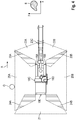
- the Figures 1 and 2 show in the side and top view, as an example of a self-propelled construction machine, a road milling machine for milling road surfaces, which is a front-loading road milling machine.
- the construction machine has a machine frame 2 carried by a chassis 1 on which a work device 3 is arranged.
- the work device 3 has a work roll, which is a milling roll.
- Milling drum 4 which is only indicated in outline, is arranged in a milling drum housing 5.
- the milling drum housing 5 is closed by an edge protection 6 on the left and right-hand side in the working direction A.
- the milling drum housing 5 On the front side in working direction A, the milling drum housing 5 is closed by a hold-down device and on the rear side by a scraper, which is shown in FIG Fig. 1 are not recognizable.
- a display unit 9 with a display 9A is located on the control panel 8.
- the milled milled material is carried away with a conveyor device 10 which extends forward in the working direction A and which is arranged on the front of the machine frame 2 so as to be pivotable in the vertical and horizontal planes.
- the construction machine has a front left drive 11A and a front right drive 11B and a rear left drive 12A and a rear right drive 12B in the working direction A, which have a front, left and right drive in the working direction A
- Lifting device 13 A, B and a rear, left and right lifting device 14 A, B are assigned, so that the height and inclination of the machine frame 2 relative to the floor surface B can be changed by retracting or extending the lifting devices.
- the drives of the construction machine can be track drives as well as wheels. With the height adjustment of the machine frame 2, the position of the edge protection floating on the floor as well as the hold-down device and the scraper relative to the machine frame, which are movably arranged on the machine frame, are also adjusted.
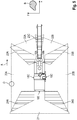
- Fig. 3 shows the components of the construction machine according to the invention that are essential for the invention in a simplified schematic representation.
- the construction machine has a position detection device 15 for detecting the height and / or inclination of the machine frame 2 with respect to the ground surface B, which can be part of a central control and computing unit 16 of the construction machine.
- the position of the machine frame 2 can be calculated from data obtained from the lifting position of the lifting devices 13 A, B and 14 A, B and / or the position of the edge protection, hold-down device or scraper.
- the positions of the individual units can be recorded with suitable sensors.
- the position detection device 15 has a computing unit 15A which receives the data from the sensors 15B.
- the computing unit 15A is configured in such a way that the height and inclination of the machine frame 2 with respect to the ground surface B are determined from the data from the sensors.
- the position detection device 15 is configured in such a way that the height of the machine frame 2 relative to the floor surface B and the inclination are derived from the stroke position of the lifting devices 13 A, B and 14 A, B detected by the sensors 15B, for example with cable sensors of the machine frame relative to the ground surface in a direction transverse to the working direction of the construction machine (rollers) and the inclination of the machine frame in the longitudinal direction of the construction machine (pitching).
- the position detection device 15 generates corresponding height, cross slope and pitch data.
- the construction machine has an image display device 17 for displaying an image of the surroundings of the construction machine in a bird's eye view, which has a camera system 18 and an image processing system 19. The image is displayed on the display 9A of the display unit 9 on the operator's platform 7 in the machine operator's field of vision.
- the structure and function of the image display device 16 are described in detail below.
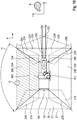
- Fig. 4 shows the construction machine in parallel alignment to the ground surface B, with all lifting devices 13 A, B and 14 A, B fully retracted and the machine frame 2 lowered into the lowest position
- Fig. 5 shows the construction machine in parallel alignment to the ground surface B, with all lifting devices 13 A, B and 14 A, B fully extended and the machine frame 2 raised to the top position.
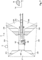
- Fig. 6 shows the construction machine inclined in the transverse direction to the left.
- the left lifting devices 13A, 14A assume the same lifting position and the right lifting devices 13B, 14B assume the same lifting position, but the right lifting devices are extended by a greater distance than the left lifting devices.
- Fig. 7 shows the construction machine tilted backwards in the longitudinal direction. In this position, the rear lifting devices 14 A, B assume the same lifting position and the front lifting devices 13 A, B assume the same lifting position, but the front lifting devices are extended by a greater distance than the rear lifting devices.
- the camera system 18 comprises several cameras 18 A, B, C, D, E provided on the machine frame 2 for recording individual, overlapping image areas of the surroundings of the construction machine from different image recording positions.
- the cameras each record a specific image area of the ground surface B.
- the position and size of the image area recorded by the camera depends on the arrangement and orientation of the Camera on the machine frame and the camera optics, in particular the focal length of the lens of the camera.
- the Figures 8A to 8D show a camera 18A of the camera system 18 in a simplified schematic illustration, which is attached to the machine frame 2.
- the camera is attached to the machine frame opposite the plane of the machine frame at a certain angle of incidence, so that the viewing direction 29 (camera axis) of the camera 18A is inclined downwards to the floor surface B when the machine frame 2 is aligned parallel to the floor surface.
- the ground surface B can be assumed to be a plane if the changes in height in the relevant area of the terrain are negligible, which is the case in practice.
- FIGS Figures 8A to 8D make it clear that a change in the distance and / or the inclination of the camera 18A to the ground surface leads to a change in the area of the ground surface B captured by the camera.
- the Figures 8A and 8B show different height positions of the machine frame 2, which is aligned parallel to the floor surface B, and FIGS Figures 8C and 8D show different inclinations of the machine frame 2 at the same height. It can be seen that, depending on the distance and / or the inclination of the camera 18A, an object O is not detected ( Figures 8A and 8C ) or is recorded ( Figures 8B and 8D ).
- a left camera 18A and a front right camera 18B preferably in the middle between the left, front and rear corner areas of the machine frame, a left side camera 18C and preferably in the middle between the right are located at the front corner areas of the machine frame 2 , front and rear corner areas of the machine frame, a right side camera 18D and preferably a rear camera 18E in the middle between the rear corner areas of the machine frame.
- each camera 18 A, B, C, D, E would record a substantially rectangular image section of the floor surface B if the viewing direction 29 of the camera (camera axis) were orthogonal to the floor surface. Due to the angle of attack, however, the camera creates a trapezoidal image area the ground surface, ie the area of the terrain lying outside the trapezoidal area is not recorded by the camera.
- the camera axes 29 (viewing directions) of the side cameras 18C and 18D and the rear camera 18E are preferably orthogonal to the long sides or the narrow side of the machine frame 2, the side cameras having a trapezoidal, side image area 20A, 20B and the rear camera a trapezoidal, record rear image area 21.
- the camera axes 29 can, however, also be directed forwards or backwards in order to capture a larger front or rear area of the terrain. Then the image areas cannot be described by isosceles trapezoids if the machine frame is aligned parallel to the ground surface.
- the camera axis 29 of the front left camera 18A runs obliquely to the left and the front right camera 18B obliquely to the right outside, so that the front left camera captures a front left image area 22A and the front right camera captures a front right image area 22B.
- Fig. 5 shows the construction machine in parallel alignment to the ground surface, with all lifting devices 13 A, B and 14 A, B fully extended and the machine frame 2 raised to the top position.
- the size of the image areas 20A, 20B, 21, 22A, 22B also changes when the machine frame 2 is inclined (rolling, pitching).
- the size of the right side image area 20B increases while the size of the left side image area 20A decreases because the left camera 18C is more inclined than the ground surface B the right camera 18D ( Fig. 6 ).
- the Figures 4 to 7 show that a change in the size of the image areas 20A, 20B, 22A, 22B, 21 can result in certain areas of the ground surface B not being detected by the image display device 17.
- an object O lying on the left is not detected ( Fig. 4 ), while the object O is detected in the top position ( Fig. 5 ).
- an object O lying on the left can no longer be detected when the construction machine rolls to the left ( Figures 5 and 6th ).
- the changes in position of the machine frame 2 to which the cameras 18 A, B, C, D, E are attached are limited by the lifting positions of the lifting devices 13 A, B and 14 A, B and the changes in the terrain to be expected.
- the arrangement or alignment and optics of the cameras is such that the image areas 20A, 20B, 21, 22A, 22B assumed to be trapezoidal overlap each other under all possible positions of the machine frame 2 when the terrain changes to be expected.
- a rear left overlap area 24A of the image areas of the side left camera 28C and the rear camera 18E and a rear right overlap area 24B of the image areas of the side right camera 18D and the rear camera 18E result.
- the position detection device 15 is connected to the image processing system 19 via a data line 25, so that the image processing system 19 can receive the height data, bank and pitch data.
- the image processing system 19 is preferably a data processing unit (CPU) on which a data processing program (software) runs.
- the image processing system 19 taking into account the height and inclination of the machine frame 2, first determines the position of the outline of the individual image areas 20A, 20B, 21, 22A, 22B shown in dotted lines, the position and size of which changes when the height and inclination of the machine frame 2 change change.
- the position of the straight outlines can be described in a Cartesian X / Y coordinate system, which lies on the surface of the ground, by their starting and end points.
- the coordinates of these points are calculated in the image processing system 19 using an algorithm which takes into account the height and inclination of the machine frame.
- the image processing system 19 determines the position and size of the overlapping areas 23A, 23B, 23C, 24A , 24B of the adjacent image areas.
- the overlapping areas can be determined, for example, by calculating an intersection of adjacent image areas.
- the image processing system 19 is configured in such a way that in the individual image areas 20A, 20B, 21, 22A, 22B, image sections 20A ', 20B', 21 ', 22A', 22B '( Figures 9 to 12 ), that is to say, suitable excerpts from the recorded image areas of the ground surface B, which can be seamlessly combined to form an overall image from a bird's eye view.
- the course of the seams depends on the position and size of the overlapping trapezoidal image sections.
- the image processing system determines the coordinates of the start and end points of the outlines of the front left overlap area 23A, the front right overlap area 23B, the front middle overlap area 23C, the rear left overlap area 24A and the rear right overlap area 24B in the X / Y coordinate system.
- the overlap areas are in the Figures 4 to 7 represented by hatching.
- the image processing system then defines the course of the seams (stitching) 26A, 26B, 26C, 27A, 27B, the following criteria being taken into account.
- the position and size of the image areas 20A, 20B, 21, 22A, 22B and thus also of the overlapping areas 23A, 23B, 23C, 24A, 24B is dependent on the height and inclination of the machine frame 2 relative to the ground surface B.
- the course of the seams 26A, 26B, 26C, 27A, 27B is determined by the image processing system 19 such that the seams run within the overlap areas 23A, 23B, 23C, 24A, 24B of the image areas 20A, 20B, 21, 22A, 22B. Consequently, the seams located within the overlap areas between the image details 20A ', 20B', 21 ', 22A', 22B 'are determined as a function of the height and inclination of the machine frame relative to the ground surface.
- the course of the seams and the position and size of the image sections is in the Figures 9 to 12 shown.
- the image processing system 19 places a left front seam 26A in the front left overlap area 23A, a right front seam 26B in the front right overlap area 23B, a middle front seam 26C in the front middle overlap area 23C, a left rear seam 27A in the rear left overlap area 24A and a right back seam 27B in the back right overlap area 24B.
- the start and end points of the seams are again described in the X / Y coordinate system by coordinates for the left front seam 26A, right front seam 26B, middle front seam 26C, left rear seam 27A and right rear seam 27B.
- FIGS 9 to 12 show how the course of the seams 26A, 26B, 26C, 27A, 27B changes as a function of the height and / or inclination of the machine frame 2. It can be seen that the opening angle ⁇ spanned by the seams increases or decreases as the inclination of the machine frame 2 increases.
- the image processing unit 19 is therefore configured in such a way that when the machine frame 2 is tilted from an orientation parallel to the floor surface B to the left, the course of the left, front and rear seams 26A, 27A of the left lateral image section, and / or the right, front and rear seam 26B, 27B of the right lateral image section is determined such that with increasing inclination of the machine frame to the left side, the opening angle ⁇ spanned by the left seams 26A, 27A decreases and that of the right seams 26B, 27B spanned opening angle ⁇ increases ( Fig.
- the course of the front seams 26A, 26B, 26C is determined by the image processing system 19 in such a way that with increasing inclination of the machine frame 2 the opening angle ⁇ spanned by the left and middle seam 26A, 26C and that of the right and middle seam 26B, 26C spanned opening angle ⁇ increases, and the course of the rear seams 17A, 27B is determined such that with increasing inclination of the machine frame 2, the opening angle ⁇ spanned by the left and right rear seam 27A, 27B decreases.
- the course of the front seams 26A, 26B, 26C is determined in such a way that, with increasing inclination of the machine frame 2, the opening angle spanned by the left and central seams 26A, 26C ⁇ and the opening angle ⁇ spanned by the right and middle seams 26B, 26C decreases, and the course of the rear seams 27A, 27B is determined in such a way that with increasing inclination of the machine frame, the opening angle spanned by the left and right, rear seam 27A, 27B ⁇ increases.
- the course of the seams is set in such a way that the starting points of the left and right, front seams 26A, 26B and the starting points of the left and right, rear seams 27A, 27B are on the corner points regardless of the height and inclination of the machine frame 2 of the machine frame.
- the starting point of the center front seam 26C is midway between the starting points of the left and right front seams Seam 26A, 26B on the longitudinal axis X of the machine frame. If the machine is banked, the starting point of the center front seam 26C is shifted to the respective side. It is approximately assumed that the starting points of the seams at the corner points of the machine frame 2 in all positions of the machine frame are always in the area of the overlap areas 23A, 23B, 23C, 24A, 24B.
- the image processing system preferably defines the end points P in such a way that the largest possible area of the environment is recorded with all cameras without gaps.
- Different criteria can be specified in this regard. For example, the forward view can be expanded at the expense of the rearward view, or vice versa. However, the view to the left can also be expanded at the expense of the view to the right, or vice versa.
- the course of the seams 26A, 26B, 26C, 27A, 27B also determines the position and size of the image details 20A ', 20B', 21 ', 22A', 22B 'to be selected depending on the height and inclination of the machine frame 2.
- the overall image is preferably a rectangular image which can be displayed on the rectangular display 9A of the display unit 9, the image details being the details of the image areas in the overall image lying between the seams.
- the image processing system 19 generates an overall image by joining the image details, the corner points of the overall image being on the end points of the seams.
- the overall image shown with the display unit 9 is identified by a dashed line 28. It shows in the Figures 9 to 12 that the overall picture 28 when lifting and lowering the machine frame 2 ( Figures 9 and 10 ) becomes larger or smaller, but maintains its symmetry with respect to the machine frame. Rolling or nodding the construction machine leads to a shift of the overall image 28 forwards or backwards or to the left or right side ( Figures 11 and 12 ).
- the image processing system 19 therefore provides different display modes that can be selected by the machine operator with an input unit on the control panel 7.
- the machine operator can specify a display mode in which only a section 28 'of the overall image 28 is shown in a bird's eye view.
- the image section 28 'from the overall image 28 is preferably again a rectangular section that is in the Figures 9 to 12 is shown in dashed lines 28 '.
- This section 28 ' is determined in such a way that for all possible positions of the construction machine a shift of the image displayed with the display unit 9 does not occur, ie areas not captured in individual positions lie outside the displayed image area.
- the section 28 ′ from the overall image 28 is dimensioned correspondingly smaller by the image processing system 19.
Landscapes
- Engineering & Computer Science (AREA)
- Mining & Mineral Resources (AREA)
- Civil Engineering (AREA)
- Structural Engineering (AREA)
- Multimedia (AREA)
- Mechanical Engineering (AREA)
- General Engineering & Computer Science (AREA)
- Signal Processing (AREA)
- Architecture (AREA)
- Chemical & Material Sciences (AREA)
- Combustion & Propulsion (AREA)
- Transportation (AREA)
- Life Sciences & Earth Sciences (AREA)
- General Life Sciences & Earth Sciences (AREA)
- Geochemistry & Mineralogy (AREA)
- Geology (AREA)
- Component Parts Of Construction Machinery (AREA)
- Closed-Circuit Television Systems (AREA)
- Image Processing (AREA)
Claims (17)
- Engin de chantier autopropulsé à chargeur frontal, en particulier fraiseuse sur route, recycleuse ou mineuse de surface, avec
un châssis d'engin (2) qui est porté par un mécanisme de déplacement (1) qui présente des mécanismes de roulement avant et arrière (11A, B ; 12A, B),
un dispositif de transport (10) dans le sens de travail (A) au niveau du côté avant du châssis d'engin (2),
un dispositif de travail (3) agencé au niveau du châssis d'engin (2) pour l'usinage du sol,
des dispositifs de levage (13A, B ; 14A, B) associés aux mécanismes de roulement individuels qui peuvent être entrés ou sortis respectivement pour le levage ou l'abaissement des mécanismes de roulement (11A, B ; 12A, B) par rapport au châssis d'engin (2) de sorte que la hauteur et/ou l'inclinaison du châssis d'engin puisse être modifiée par rapport à la surface de sol (B),
un dispositif de détection de position (15) détectant la hauteur et/ou l'inclinaison du châssis d'engin (2) par rapport à la surface de sol (B) et
un dispositif d'affichage d'image (17) pour l'affichage d'une image de l'environnement de l'engin de chantier qui est réalisé comme un dispositif d'affichage d'image pour l'affichage d'une image de l'environnement de l'engin de chantier dans la perspective à vol d'oiseau qui présente un système de caméra (18) avec plusieurs caméras (18, 18B, 18C, 18D, 18E) prévues au niveau du châssis d'engin pour l'acquisition de zones d'image (20A, 20B, 21, 22A, 22B) individuelles de l'environnement d'engin de chantier se chevauchant à partir de différentes positions d'acquisition d'image et un système de traitement d'image (19) coagissant avec le dispositif de détection de position (17) qui est configuré de telle manière que des sections d'image (20A', 20B', 21', 22A', 22B') des zones d'image individuelles (20A, 20B, 21, 22A, 22B) soient réunies en une image globale (28) dans la perspective à vol d'oiseau, dans lequel le tracé des joints (26A, 26B, 26C, 27A, 27B) entre les sections d'image (20A', 20B', 21', 22A', 22B') est fixé en fonction de la hauteur et/ou de l'inclinaison du châssis d'engin (2) par rapport à la surface de sol (B),
dans lequel le système de caméra (18) présente :deux caméras avant (18A, 18B) dans le sens de travail qui sont agencées des deux côtés du dispositif de transport (10) de sorte que deux zones d'image avant (22A, 22B) soient acquises, lesquelles se chevauchent,une caméra gauche (18C) au niveau du côté longitudinal gauche dans le sens de travail de l'engin de chantier et une caméra droite (18D) au niveau du côté longitudinal droit dans le sens de travail (A) de l'engin de chantier de sorte que des zones d'image gauche et droite (20A, 20B) soient acquises, etune caméra arrière (18E) dans le sens de travail (A) de sorte qu'une zone d'image arrière (21) soit acquise. - Engin de chantier autopropulsé à chargeur arrière, en particulier fraiseuse sur route, recycleuse ou mineuse de surface, avec
un châssis d'engin (2) qui est porté par un mécanisme de déplacement (1) qui présente des mécanismes de roulement avant et arrière (11A, B ; 12A, B),
un dispositif de transport (10) dans le sens de travail (A) au niveau du côté arrière du châssis d'engin (2),
un dispositif de travail (3) agencé au niveau du châssis d'engin (2) pour l'usinage du sol,
des dispositifs de levage (13A, B ; 14A, B) associés aux mécanismes de roulement individuels qui peuvent être entrés ou sortis respectivement pour le levage ou l'abaissement des mécanismes de roulement (11A, B ; 12A, B) par rapport au châssis d'engin (2) de sorte que la hauteur et/ou l'inclinaison du châssis d'engin puisse être modifiée par rapport à la surface de sol (B),
un dispositif de détection de position (15) détectant la hauteur et/ou l'inclinaison du châssis d'engin (2) par rapport à la surface de sol (B) et
un dispositif d'affichage d'image (17) pour l'affichage d'une image de l'environnement de l'engin de chantier qui est réalisé comme un dispositif d'affichage d'image pour l'affichage d'une image de l'environnement de l'engin de chantier dans la perspective à vol d'oiseau qui présente un système de caméra (18) avec plusieurs caméras (18, 18B, 18C, 18D, 18E) prévues au niveau du châssis d'engin pour l'acquisition de zones d'image (20A, 20B, 21, 22A, 22B) individuelles de l'environnement d'engin de chantier se chevauchant à partir de différentes positions d'acquisition d'image et un système de traitement d'image (19) coagissant avec le dispositif de détection de position (17) qui est configuré de telle manière que des sections d'image (20A', 20B', 21', 22A', 22B') des zones d'image individuelles (20A, 20B, 21, 22A, 22B) soient réunies en une image globale (28) dans la perspective à vol d'oiseau, dans lequel le tracé des joints (26A, 26B, 26C, 27A, 27B) entre les sections d'image (20A', 20B', 21', 22A', 22B') est fixé en fonction de la hauteur et/ou de l'inclinaison du châssis d'engin (2) par rapport à la surface de sol (B),
dans lequel le système de caméra (18) présente :deux caméras arrière (18A, 18B) dans le sens de travail qui sont agencées des deux côtés du dispositif de transport (10) de sorte que deux zones d'image arrière (22A, 22B) soient acquises, lesquelles se chevauchent,une caméra gauche (18C) au niveau du côté longitudinal gauche dans le sens de travail de l'engin de chantier et une caméra droite (18D) au niveau du côté longitudinal droit dans le sens de travail (A) de l'engin de chantier de sorte que des zones d'image gauche et droite (20A, 20B) soient acquises, etune caméra avant (18E) dans le sens de travail (A) de sorte qu'une zone d'image avant (21) soit acquise. - Engin de chantier autopropulsé selon la revendication 1 ou 2, caractérisé en ce que le dispositif de détection de position (15) est configuré de telle manière que des données de hauteur décrivant la hauteur du châssis d'engin (2) par rapport à la surface de sol (B) et/ou des données d'inclinaison transversale décrivant l'inclinaison du châssis d'engin (2) par rapport à la surface de sol (B) dans une direction transversale au sens de travail (A) de l'engin de chantier et/ou des données d'inclinaison longitudinale décrivant l'inclinaison du châssis d'engin par rapport à la surface de sol dans la direction longitudinale de l'engin de chantier soient générées, et le système de traitement d'image (19) est configuré de telle manière que sur la base des données de hauteur et/ou des données d'inclinaison transversale et/ou des données d'inclinaison longitudinale le tracé des joints (26A, 26B, 26C, 27A, 27B) entre les sections d'image soit fixé de telle manière que les joints se trouvent dans les zones de chevauchement.
- Engin de chantier autopropulsé selon la revendication 3, caractérisé en ce que le système de traitement d'image (19) est configuré de telle manière que les lignes de contour des zones d'image individuelles (20A, 20B, 21, 22A, 22B) des caméras (18A, 18B, 18C, 18D, 18E) sont déterminées sur la base des données de hauteur et/ou des données d'inclinaison transversale et/ou des données d'inclinaison longitudinale pour la fixation du tracé des joints (26A, 26B, 26C, 27A, 27B) entre les sections d'image et des zones d'image sont déterminées sur la base des lignes de contour les zones de chevauchement (23A, 23B, 23C, 24A, 24B).
- Engin de chantier autopropulsé selon l'une des revendications 1 à 4, caractérisé en ce que le système de traitement d'image (19) est configuré de telle manière que des sections d'image (20A', 20B', 21', 22A', 22B') des zones d'image (20A, 20B, 21, 22A, 22B) individuelles soient assemblées en une image globale (28) dans la perspective à vol d'oiseau sensiblement rectangulaire.
- Engin de chantier autopropulsé selon l'une des revendications 1 à 5, caractérisé en ce que le système de traitement d'image (19) est configuré de telle manière qu'une section (28') de l'image globale (28) dans la perspective à vol d'oiseau symétrique par rapport aux côtés longitudinaux et/ou aux côtés transversaux du châssis d'engin (2) soit affichée.
- Engin de chantier autopropulsé selon la revendication 1, caractérisé en ce que les deux caméras avant (18A, 18B) sont agencées au niveau des zones de coin avant du châssis d'engin (2) et/ou les caméras gauche et droite (18C, 18D) sont agencées au milieu entre les zones de coin avant et arrière du châssis d'engin (2) et la caméra arrière (18E) est agencée au milieu entre les zones de coin arrière du châssis d'engin (2).
- Engin de chantier autopropulsé selon la revendication 7, caractérisé en ce que le système de traitement d'image (19) est configuré de telle manière que le tracé des joints (26A, 26B, 26C, 27A, 27B) soit fixé de telle manière qu'une section d'image (22A', 22B') avant, gauche et droite dans la direction de travail (A) soit définie, dans lequel la section d'image (22A') avant gauche est délimitée latéralement par un joint avant gauche (26A) qui s'étend depuis la zone de coin avant gauche, et un joint médian avant (26C) qui s'étend depuis le côté avant, et la section d'image avant droite (22B') est délimitée latéralement par un joint avant droit (26B) qui s'étend depuis la zone de coin avant droite, et le joint médian avant (26C),
qu'une section d'image (20A', 20B') latérale, gauche et droite dans la direction de travail (A) soit définie, dans lequel la section d'image (20A') latérale gauche est délimitée latéralement par un joint (27A) arrière gauche qui s'étend depuis la zone de coin arrière gauche, et le joint avant gauche (26A), et la section d'image (20B') latérale droite est délimitée par un joint arrière droit (27B) qui s'étend depuis la zone de coin arrière droit, et le joint avant droit (26B), et
qu'une section d'image (21') arrière dans la direction de travail (A) soit définie, laquelle est délimitée latéralement par les joints arrière, gauche et droit (27A, 27B). - Engin de chantier autopropulsé selon la revendication 8, caractérisé en ce que le système de traitement d'image (19) est configuré de telle manière que, en cas d'inclinaison transversale du châssis d'engin (2) à partir d'une orientation parallèle à la surface de sol (B) sur le côté gauche, le tracé des joints gauches, avant et arrière (26A, 27A) de la section d'image (20A') latérale gauche, et/ou des joints droits, avant et arrière (26B, 27B) de la section d'image (20B') latérale droite soit fixé de telle manière qu'avec une inclinaison croissante du châssis d'engin (2) sur le côté gauche l'angle d'ouverture (α) défini par les joints gauches (26A, 27A) diminue et l'angle d'ouverture défini par les joints droits (26B, 27B) augmente, et, en cas d'inclinaison transversale du châssis d'engin (2) à partir d'une orientation parallèle à la surface de sol (B) sur le côté droit, soit fixé de telle manière qu'avec une inclinaison croissante du châssis d'engin (2) sur le côté droit l'angle d'ouverture (α) défini par les joints gauches (26A, 27A) augmente et l'angle d'ouverture (α) défini par les joints droits (26B, 27B) diminue.
- Engin de chantier autopropulsé selon la revendication 8 ou 9, caractérisé en ce que le système de traitement d'image (19) est configuré de telle manière qu'en cas d'inclinaison longitudinale du châssis d'engin (2) vers l'avant à partir d'une orientation parallèle à la surface de sol (B), le tracé des joints avant (26A, 26B, 26C) soit fixé de telle manière qu'avec une inclinaison croissante du châssis d'engin (2) vers l'avant l'angle d'ouverture (α) défini par les joints gauche et médian (26A, 26C) et l'angle d'ouverture (26A, 27A) défini par les joints droit et médian (26B, 26C) diminue, et le tracé des joints arrière soit fixé de telle manière qu'avec une inclinaison croissante du châssis d'engin vers l'avant l'angle d'ouverture (α) défini par les joints arrière, gauche et droit (27A, 27B) augmente et qu'en cas d'inclinaison longitudinale du châssis d'engin (2) vers l'arrière à partir d'une orientation parallèle à la surface de sol (B), le tracé des joints avant soit fixé de telle manière qu'avec une inclinaison croissante du châssis d'engin (2) vers l'arrière l'angle d'ouverture (α) défini par les joints avant, gauche et médian (26A, 26C) et l'angle d'ouverture (α) défini par les joints avant, droit et médian (26B, 26C) augmente, et le tracé des joints arrière soit fixé de telle manière qu'avec une inclinaison croissante du châssis d'engin (2) vers l'arrière l'angle d'ouverture (α) défini par les joints arrière, gauche et droit (27A, 27B) diminue.
- Engin de chantier autopropulsé selon l'une des revendications 1 à 10, caractérisé en ce que le dispositif de détection de position (15) présente des capteurs (15A) détectant les positions de levage des dispositifs de levage (13A,
B ; 14A, B) et une unité de calcul (15B) qui est configurée de telle manière qu'à partir des positions de levage des dispositifs de levage les données de hauteur et/ou les données d'inclinaison transversale et/ou les données d'inclinaison longitudinale soient calculées. - Procédé d'affichage de l'image de l'environnement d'un engin de chantier autopropulsé à chargeur avant, en particulier fraiseuse sur route, recycleuse, mineuse de surface qui présente :un châssis d'engin qui est porté par un mécanisme de déplacement qui présente des mécanismes de roulement avant et arrière,un dispositif de transport (10) dans la direction de travail (A) au niveau du côté avant du châssis d'engin (2),au moins un dispositif de travail agencé au niveau du châssis d'engin pour l'usinage du sol,des dispositifs de levage associés aux mécanismes de roulement individuels qui peuvent être entrés ou sortis respectivement pour le levage ou l'abaissement des mécanismes de roulement par rapport au châssis d'engin de sorte que la hauteur et/ou l'inclinaison du châssis d'engin puisse être modifiée par rapport à la surface de sol,dans lequella hauteur et/ou l'inclinaison du châssis d'engin par rapport à la surface de sol est détectée et une image de l'environnement de l'engin de chantier dans la perspective à vol d'oiseau est affichée, dans lequel avec plusieurs caméras prévues au niveau du châssis d'engin des zones d'image individuelles de l'environnement d'engin de chantier se chevauchant sont acquises à partir de différentes positions d'acquisition d'image et des sections d'image des zones d'image individuelles sont réunies en une image globale dans la perspective à vol d'oiseau, dans lequel le tracé des joints entre les sections d'image est fixé en fonction de la hauteur et/ou de l'inclinaison du châssis d'engin par rapport à la surface de sol, etdans lequella direction de travail, deux zones d'image avant qui se chevauchent sont acquises avec deux caméras avant dans la direction de travail qui sont agencées des deux côtés du dispositif de transport, la direction de travailla direction de travail des zones d'image gauche et droite sont acquises , avec une caméra gauche au niveau du côté longitudinal gauche dans la direction de travail de l'engin de chantier et une caméra droite au niveau du côté longitudinal droit dans la direction de travail de l'engin de chantier et la direction de travail une zone d'image arrière est acquise avec une caméra arrière dans la direction de travail.
- Procédé pour l'affichage de l'image de l'environnement d'un engin de chantier autopropulsé à chargeur arrière, en particulier fraiseuse sur route, recycleuse, mineuse de surface qui présente :un châssis d'engin qui est porté par un mécanisme de déplacement qui présente des mécanismes de roulement avant et arrière,un dispositif de transport (10) dans la direction de travail (A) au niveau du côté arrière du châssis d'engin (2),au moins un dispositif de travail agencé au niveau du châssis d'engin pour l'usinage du sol,des dispositifs de levage associés aux mécanismes de roulement individuels qui peuvent être entrés ou sortis respectivement pour le levage ou l'abaissement des mécanismes de roulement par rapport au châssis d'engin de sorte que la hauteur et/ou l'inclinaison du châssis d'engin puisse être modifiée par rapport à la surface de sol,dans lequella hauteur et/ou l'inclinaison du châssis d'engin par rapport à la surface de sol est détectée et une image de l'environnement de l'engin de chantier dans la perspective à vol d'oiseau est affichée, dans lequel avec plusieurs caméras prévues au niveau du châssis d'engin des zones d'image individuelles de l'environnement d'engin de chantier se chevauchant sont acquises à partir de différentes positions d'acquisition d'image et des sections d'image des zones d'image individuelles sont réunies en une image globale dans la perspective à vol d'oiseau, dans lequel le tracé des joints entre les sections d'image est fixé en fonction de la hauteur et/ou de l'inclinaison du châssis d'engin par rapport à la surface de sol, etdans lequel deux zones d'image arrière qui se chevauchent sont acquises avec deux caméras arrière dans la direction de travail qui sont agencées des deux côtés du dispositif de transport, la direction de travailla direction de travaildes zones d'image gauche et droite sont acquises avec une caméra gauche au niveau du côté longitudinal gauche dans la direction de travail de l'engin de chantier et une caméra droite au niveau du côté longitudinal droit dans la direction de travail de l'engin de chantier, et une zone d'image avant est acquise avec une caméra avant.
- Procédé selon la revendication 12 ou 13, caractérisé en ce que les sections d'image des zones d'image individuelles sont assemblées en une image globale dans la perspective à vol d'oiseau sensiblement rectangulaire.
- Procédé selon l'une des revendications 12 à 14, caractérisé en ce qu'une section de l'image globale dans la perspective à vol d'oiseau symétrique par rapport aux côtés longitudinaux et/ou aux côtés transversaux du châssis d'engin est affichée.
- Procédé selon la revendication 12, caractérisé en ce qu'en cas d'inclinaison transversale du châssis d'engin à partir d'une orientation parallèle à la surface de sol sur le côté gauche le tracé des joints gauches, avant et arrière de la section d'image latérale gauche, et/ou des joints droits, avant et arrière de la section d'image latérale droite est fixé de telle manière qu'avec une inclinaison croissante du châssis d'engin sur le côté gauche l'angle d'ouverture défini par les joints gauches diminue et l'angle d'ouverture défini par les joints droit augmente, et en cas d'inclinaison transversale du châssis d'engin à partir d'une orientation parallèle à la surface de sol sur le côté droit est fixé de telle manière qu'avec une inclinaison croissante du châssis d'engin sur le côté droit l'angle d'ouverture défini par les joints gauches augmente et l'angle d'ouverture défini par les joints droit diminue.
- Procédé selon la revendication 12 ou 16, caractérisé en ce que
en cas d'inclinaison longitudinale du châssis d'engin vers l'avant à partir d'une orientation parallèle à la surface de sol, le tracé des joints avant est fixé de telle manière qu'avec une inclinaison croissante du châssis d'engin vers l'avant l'angle d'ouverture défini par les joints gauche et médian et l'angle d'ouverture défini par les joints droit et médian diminue, et le tracé des joints arrière est fixé de telle manière qu'avec une inclinaison croissante du châssis d'engin vers l'avant l'angle d'ouverture défini par les joints arrières, gauche et droit augmente et
qu'en cas d'inclinaison longitudinale du châssis d'engin vers l'arrière à partir d'une orientation parallèle à la surface de sol, le tracé des joints avant est fixé de telle manière qu'avec une inclinaison croissante du châssis d'engin vers l'arrière l'angle d'ouverture défini par les joints gauche et médian et l'angle d'ouverture défini par les joints droit et médian augmente, et le tracé des joints arrière est fixé de telle manière qu'avec une inclinaison croissante du châssis d'engin vers l'arrière l'angle d'ouverture défini par les joints arrière, gauche et droit diminue.
Applications Claiming Priority (1)
| Application Number | Priority Date | Filing Date | Title |
|---|---|---|---|
| DE102015010009.2A DE102015010009A1 (de) | 2015-08-05 | 2015-08-05 | Selbstfahrende Baumaschine und Verfahren zur Anzeige der Umgebung einer selbstfahrenden Baumaschine |
Publications (2)
| Publication Number | Publication Date |
|---|---|
| EP3135823A1 EP3135823A1 (fr) | 2017-03-01 |
| EP3135823B1 true EP3135823B1 (fr) | 2020-12-02 |
Family
ID=56511415
Family Applications (1)
| Application Number | Title | Priority Date | Filing Date |
|---|---|---|---|
| EP16180881.1A Active EP3135823B1 (fr) | 2015-08-05 | 2016-07-22 | Engin automobile et procede d'affichage de l'environnement d'un chargeur frontal ou arriere |
Country Status (4)
| Country | Link |
|---|---|
| US (1) | US10378162B2 (fr) |
| EP (1) | EP3135823B1 (fr) |
| CN (2) | CN206279433U (fr) |
| DE (1) | DE102015010009A1 (fr) |
Families Citing this family (10)
| Publication number | Priority date | Publication date | Assignee | Title |
|---|---|---|---|---|
| DE102015010009A1 (de) * | 2015-08-05 | 2017-02-09 | Wirtgen Gmbh | Selbstfahrende Baumaschine und Verfahren zur Anzeige der Umgebung einer selbstfahrenden Baumaschine |
| WO2017191853A1 (fr) * | 2017-06-28 | 2017-11-09 | 株式会社小松製作所 | Dispositif et système d'affichage pour engin de chantier |
| US10526766B2 (en) * | 2017-07-31 | 2020-01-07 | Deere & Company | Work machines and methods and systems to control and determine a position of an associated implement |
| JP6900897B2 (ja) * | 2017-12-25 | 2021-07-07 | コベルコ建機株式会社 | 建設機械の障害物検出装置 |
| US20210363732A1 (en) * | 2018-04-30 | 2021-11-25 | Volvo Construction Equipment Ab | System and method for selectively displaying image data in a working machine |
| DE102018005117A1 (de) | 2018-06-28 | 2018-12-20 | Daimler Ag | Verfahren zum Betreiben eines Fahrerassistenzsystems sowie Fahrerassistenzsystem |
| JP7267755B2 (ja) * | 2019-01-23 | 2023-05-02 | 株式会社小松製作所 | 作業機械のためのシステム及び方法 |
| JP7458850B2 (ja) | 2020-03-26 | 2024-04-01 | 住友重機械建機クレーン株式会社 | 作業機械の周囲表示装置 |
| US11640715B2 (en) | 2021-06-21 | 2023-05-02 | Caterpillar Paving Products Inc. | Birds eye view camera for an asphalt paver |
| US11680387B1 (en) | 2022-04-21 | 2023-06-20 | Deere & Company | Work vehicle having multi-purpose camera for selective monitoring of an area of interest |
Family Cites Families (19)
| Publication number | Priority date | Publication date | Assignee | Title |
|---|---|---|---|---|
| DE102006003538B3 (de) | 2006-01-24 | 2007-07-19 | Daimlerchrysler Ag | Verfahren zum Zusammenfügen mehrerer Bildaufnahmen zu einem Gesamtbild in der Vogelperspektive |
| JP4859652B2 (ja) * | 2006-12-15 | 2012-01-25 | アルパイン株式会社 | 画像表示装置 |
| DE202007005756U1 (de) * | 2007-04-19 | 2008-08-28 | Wirtgen Gmbh | Selbstfahrende Baumaschine |
| JP2008312004A (ja) | 2007-06-15 | 2008-12-25 | Sanyo Electric Co Ltd | カメラシステム及び機械装置 |
| JP2010241548A (ja) | 2009-04-03 | 2010-10-28 | Kansai Electric Power Co Inc:The | クレーンの安全確認装置 |
| KR20120053713A (ko) * | 2010-11-18 | 2012-05-29 | 에스엘 주식회사 | 차량용 카메라의 제어 장치 및 방법 |
| DE102011077143A1 (de) | 2011-06-07 | 2012-12-13 | Robert Bosch Gmbh | Fahrzeugkamerasystem und Verfahren zur Bereitstellung eines lückenlosen Bildes der Fahrzeugumgebung |
| WO2013058093A1 (fr) * | 2011-10-18 | 2013-04-25 | 日立建機株式会社 | Dispositif pour surveiller l'environnement de machines |
| DE102011088332B4 (de) | 2011-12-13 | 2021-09-02 | Robert Bosch Gmbh | Verfahren zur Verbesserung der Objektdetektion bei Multikamerasystemen |
| JP5888956B2 (ja) | 2011-12-13 | 2016-03-22 | 住友建機株式会社 | ショベル及び該ショベルの周囲画像表示方法 |
| CN102493325B (zh) * | 2011-12-17 | 2013-10-23 | 于健 | 一种路面铣刨机 |
| DE102013006464B4 (de) * | 2012-04-16 | 2020-03-19 | Bomag Gmbh | Baumaschine mit einer Manövriereinrichtung, Verfahren zur Erleichterung des Manövrierens einer Baumaschine und Manövriereinrichtung für eine Baumaschine |
| JP2013253402A (ja) | 2012-06-06 | 2013-12-19 | Hitachi Constr Mach Co Ltd | 作業機械の周囲監視装置 |
| CN104380724B (zh) * | 2012-06-08 | 2017-09-12 | 日立建机株式会社 | 自行式工业机械的显示装置 |
| DE102012020655A1 (de) * | 2012-10-19 | 2014-04-24 | Wirtgen Gmbh | Selbstfahrende Baumaschine |
| DE102013002079A1 (de) | 2013-02-06 | 2014-08-07 | Volvo Construction Equipment Germany GmbH | Baumaschine |
| US10179543B2 (en) * | 2013-02-27 | 2019-01-15 | Magna Electronics Inc. | Multi-camera dynamic top view vision system |
| US20150070498A1 (en) | 2013-09-06 | 2015-03-12 | Caterpillar Inc. | Image Display System |
| DE102015010009A1 (de) * | 2015-08-05 | 2017-02-09 | Wirtgen Gmbh | Selbstfahrende Baumaschine und Verfahren zur Anzeige der Umgebung einer selbstfahrenden Baumaschine |
-
2015
- 2015-08-05 DE DE102015010009.2A patent/DE102015010009A1/de active Pending
-
2016
- 2016-07-22 EP EP16180881.1A patent/EP3135823B1/fr active Active
- 2016-07-26 US US15/219,597 patent/US10378162B2/en active Active
- 2016-08-05 CN CN201620844986.5U patent/CN206279433U/zh not_active Withdrawn - After Issue
- 2016-08-05 CN CN201610635378.8A patent/CN106436544B/zh active Active
Non-Patent Citations (1)
| Title |
|---|
| None * |
Also Published As
| Publication number | Publication date |
|---|---|
| DE102015010009A1 (de) | 2017-02-09 |
| EP3135823A1 (fr) | 2017-03-01 |
| CN106436544B (zh) | 2020-05-19 |
| CN106436544A (zh) | 2017-02-22 |
| US10378162B2 (en) | 2019-08-13 |
| CN206279433U (zh) | 2017-06-27 |
| US20170037586A1 (en) | 2017-02-09 |
Similar Documents
| Publication | Publication Date | Title |
|---|---|---|
| EP3135823B1 (fr) | Engin automobile et procede d'affichage de l'environnement d'un chargeur frontal ou arriere | |
| EP3135822B1 (fr) | Engin automobile et procede d'affichage de l'environnement d'un engin automobile | |
| EP3501897B1 (fr) | Système de visualisation permettant d'apprehender l'environnement d'un véhicule | |
| EP2700748B1 (fr) | Fraiseuse automotrice et procédé de conduite d'une fraiseuse automotrice | |
| DE102013006464B4 (de) | Baumaschine mit einer Manövriereinrichtung, Verfahren zur Erleichterung des Manövrierens einer Baumaschine und Manövriereinrichtung für eine Baumaschine | |
| EP2441888B1 (fr) | Engin automobile | |
| DE112013002543B4 (de) | Displayvorrichtung für Industriemaschine mit Eigenantrieb | |
| EP2954120B1 (fr) | Engin de chantier comportant un dispositif de surveillance | |
| DE112013000873T5 (de) | Peripherieüberwachungsvorrichtung für Transportfahrzeug | |
| DE112015006349T5 (de) | Arbeitsfahrzeug | |
| DE102019126417A1 (de) | Sensor für einen motorgrader | |
| EP3323940A1 (fr) | Fraiseuse automotrice et procédé de commande d'une fraiseuse automotrice | |
| DE112015006343T5 (de) | Verfahren zum Erzeugen von Bilddaten | |
| DE112015006347T5 (de) | Bildaufnahmevorrichtung | |
| DE102019119008A1 (de) | System zur objekterfassung und arbeitsaufsatzstellungserfassung | |
| DE102018132546A1 (de) | System und verfahren zur visuellen schneidwerkzeug-verlaufsdarstellung | |
| DE102018200060B4 (de) | Verfahren zum Betreiben einer mobilen Arbeitsmaschine und mobile Arbeitsmaschine | |
| EP3794927A1 (fr) | Machine de travail agricole | |
| WO2021078711A1 (fr) | Procédé de délivrance d'un signal de commande à une unité d'un véhicule | |
| DE102021201728A1 (de) | System und verfahren zur übermittlung des vorhandenseins von nahegelegenen objekten in einem arbeitsbereich | |
| DE112020007380T5 (de) | Klappbare maschine, panoramischesrundumsicht-system und kalibrierungsverfahren für dieses system | |
| DE102014107810A1 (de) | Verfahren zur Visualisierung der Abstützposition und/oder des Ausfahrweges zumindest einer Stütze eines Fahrzeuges sowie Fahrzeug mit zumindest einer Stütze | |
| DE102021208874A1 (de) | Arbeitsfahrzeug | |
| DE102021203109A1 (de) | Mehrdimensionales visualisierungs- und steuersystem für mobile maschinenpfade | |
| DE112015006346T5 (de) | Bildaufnahmevorrichtung |
Legal Events
| Date | Code | Title | Description |
|---|---|---|---|
| PUAI | Public reference made under article 153(3) epc to a published international application that has entered the european phase |
Free format text: ORIGINAL CODE: 0009012 |
|
| STAA | Information on the status of an ep patent application or granted ep patent |
Free format text: STATUS: THE APPLICATION HAS BEEN PUBLISHED |
|
| AK | Designated contracting states |
Kind code of ref document: A1 Designated state(s): AL AT BE BG CH CY CZ DE DK EE ES FI FR GB GR HR HU IE IS IT LI LT LU LV MC MK MT NL NO PL PT RO RS SE SI SK SM TR |
|
| AX | Request for extension of the european patent |
Extension state: BA ME |
|
| STAA | Information on the status of an ep patent application or granted ep patent |
Free format text: STATUS: REQUEST FOR EXAMINATION WAS MADE |
|
| 17P | Request for examination filed |
Effective date: 20170829 |
|
| RBV | Designated contracting states (corrected) |
Designated state(s): AL AT BE BG CH CY CZ DE DK EE ES FI FR GB GR HR HU IE IS IT LI LT LU LV MC MK MT NL NO PL PT RO RS SE SI SK SM TR |
|
| GRAP | Despatch of communication of intention to grant a patent |
Free format text: ORIGINAL CODE: EPIDOSNIGR1 |
|
| STAA | Information on the status of an ep patent application or granted ep patent |
Free format text: STATUS: GRANT OF PATENT IS INTENDED |
|
| INTG | Intention to grant announced |
Effective date: 20200610 |
|
| GRAS | Grant fee paid |
Free format text: ORIGINAL CODE: EPIDOSNIGR3 |
|
| GRAA | (expected) grant |
Free format text: ORIGINAL CODE: 0009210 |
|
| STAA | Information on the status of an ep patent application or granted ep patent |
Free format text: STATUS: THE PATENT HAS BEEN GRANTED |
|
| AK | Designated contracting states |
Kind code of ref document: B1 Designated state(s): AL AT BE BG CH CY CZ DE DK EE ES FI FR GB GR HR HU IE IS IT LI LT LU LV MC MK MT NL NO PL PT RO RS SE SI SK SM TR |
|
| REG | Reference to a national code |
Ref country code: GB Ref legal event code: FG4D Free format text: NOT ENGLISH |
|
| REG | Reference to a national code |
Ref country code: AT Ref legal event code: REF Ref document number: 1341099 Country of ref document: AT Kind code of ref document: T Effective date: 20201215 Ref country code: CH Ref legal event code: EP |
|
| REG | Reference to a national code |
Ref country code: IE Ref legal event code: FG4D Free format text: LANGUAGE OF EP DOCUMENT: GERMAN |
|
| REG | Reference to a national code |
Ref country code: DE Ref legal event code: R096 Ref document number: 502016011819 Country of ref document: DE |
|
| PG25 | Lapsed in a contracting state [announced via postgrant information from national office to epo] |
Ref country code: RS Free format text: LAPSE BECAUSE OF FAILURE TO SUBMIT A TRANSLATION OF THE DESCRIPTION OR TO PAY THE FEE WITHIN THE PRESCRIBED TIME-LIMIT Effective date: 20201202 Ref country code: NO Free format text: LAPSE BECAUSE OF FAILURE TO SUBMIT A TRANSLATION OF THE DESCRIPTION OR TO PAY THE FEE WITHIN THE PRESCRIBED TIME-LIMIT Effective date: 20210302 Ref country code: GR Free format text: LAPSE BECAUSE OF FAILURE TO SUBMIT A TRANSLATION OF THE DESCRIPTION OR TO PAY THE FEE WITHIN THE PRESCRIBED TIME-LIMIT Effective date: 20210303 Ref country code: FI Free format text: LAPSE BECAUSE OF FAILURE TO SUBMIT A TRANSLATION OF THE DESCRIPTION OR TO PAY THE FEE WITHIN THE PRESCRIBED TIME-LIMIT Effective date: 20201202 |
|
| REG | Reference to a national code |
Ref country code: NL Ref legal event code: MP Effective date: 20201202 |
|
| PG25 | Lapsed in a contracting state [announced via postgrant information from national office to epo] |
Ref country code: BG Free format text: LAPSE BECAUSE OF FAILURE TO SUBMIT A TRANSLATION OF THE DESCRIPTION OR TO PAY THE FEE WITHIN THE PRESCRIBED TIME-LIMIT Effective date: 20210302 Ref country code: LV Free format text: LAPSE BECAUSE OF FAILURE TO SUBMIT A TRANSLATION OF THE DESCRIPTION OR TO PAY THE FEE WITHIN THE PRESCRIBED TIME-LIMIT Effective date: 20201202 Ref country code: SE Free format text: LAPSE BECAUSE OF FAILURE TO SUBMIT A TRANSLATION OF THE DESCRIPTION OR TO PAY THE FEE WITHIN THE PRESCRIBED TIME-LIMIT Effective date: 20201202 Ref country code: PL Free format text: LAPSE BECAUSE OF FAILURE TO SUBMIT A TRANSLATION OF THE DESCRIPTION OR TO PAY THE FEE WITHIN THE PRESCRIBED TIME-LIMIT Effective date: 20201202 |
|
| PG25 | Lapsed in a contracting state [announced via postgrant information from national office to epo] |
Ref country code: HR Free format text: LAPSE BECAUSE OF FAILURE TO SUBMIT A TRANSLATION OF THE DESCRIPTION OR TO PAY THE FEE WITHIN THE PRESCRIBED TIME-LIMIT Effective date: 20201202 Ref country code: NL Free format text: LAPSE BECAUSE OF FAILURE TO SUBMIT A TRANSLATION OF THE DESCRIPTION OR TO PAY THE FEE WITHIN THE PRESCRIBED TIME-LIMIT Effective date: 20201202 |
|
| REG | Reference to a national code |
Ref country code: LT Ref legal event code: MG9D |
|
| PG25 | Lapsed in a contracting state [announced via postgrant information from national office to epo] |
Ref country code: EE Free format text: LAPSE BECAUSE OF FAILURE TO SUBMIT A TRANSLATION OF THE DESCRIPTION OR TO PAY THE FEE WITHIN THE PRESCRIBED TIME-LIMIT Effective date: 20201202 Ref country code: CZ Free format text: LAPSE BECAUSE OF FAILURE TO SUBMIT A TRANSLATION OF THE DESCRIPTION OR TO PAY THE FEE WITHIN THE PRESCRIBED TIME-LIMIT Effective date: 20201202 Ref country code: SM Free format text: LAPSE BECAUSE OF FAILURE TO SUBMIT A TRANSLATION OF THE DESCRIPTION OR TO PAY THE FEE WITHIN THE PRESCRIBED TIME-LIMIT Effective date: 20201202 Ref country code: LT Free format text: LAPSE BECAUSE OF FAILURE TO SUBMIT A TRANSLATION OF THE DESCRIPTION OR TO PAY THE FEE WITHIN THE PRESCRIBED TIME-LIMIT Effective date: 20201202 Ref country code: RO Free format text: LAPSE BECAUSE OF FAILURE TO SUBMIT A TRANSLATION OF THE DESCRIPTION OR TO PAY THE FEE WITHIN THE PRESCRIBED TIME-LIMIT Effective date: 20201202 Ref country code: SK Free format text: LAPSE BECAUSE OF FAILURE TO SUBMIT A TRANSLATION OF THE DESCRIPTION OR TO PAY THE FEE WITHIN THE PRESCRIBED TIME-LIMIT Effective date: 20201202 Ref country code: PT Free format text: LAPSE BECAUSE OF FAILURE TO SUBMIT A TRANSLATION OF THE DESCRIPTION OR TO PAY THE FEE WITHIN THE PRESCRIBED TIME-LIMIT Effective date: 20210405 |
|
| REG | Reference to a national code |
Ref country code: DE Ref legal event code: R097 Ref document number: 502016011819 Country of ref document: DE |
|
| PG25 | Lapsed in a contracting state [announced via postgrant information from national office to epo] |
Ref country code: IS Free format text: LAPSE BECAUSE OF FAILURE TO SUBMIT A TRANSLATION OF THE DESCRIPTION OR TO PAY THE FEE WITHIN THE PRESCRIBED TIME-LIMIT Effective date: 20210402 |
|
| PLBE | No opposition filed within time limit |
Free format text: ORIGINAL CODE: 0009261 |
|
| STAA | Information on the status of an ep patent application or granted ep patent |
Free format text: STATUS: NO OPPOSITION FILED WITHIN TIME LIMIT |
|
| PG25 | Lapsed in a contracting state [announced via postgrant information from national office to epo] |
Ref country code: AL Free format text: LAPSE BECAUSE OF FAILURE TO SUBMIT A TRANSLATION OF THE DESCRIPTION OR TO PAY THE FEE WITHIN THE PRESCRIBED TIME-LIMIT Effective date: 20201202 |
|
| 26N | No opposition filed |
Effective date: 20210903 |
|
| PG25 | Lapsed in a contracting state [announced via postgrant information from national office to epo] |
Ref country code: DK Free format text: LAPSE BECAUSE OF FAILURE TO SUBMIT A TRANSLATION OF THE DESCRIPTION OR TO PAY THE FEE WITHIN THE PRESCRIBED TIME-LIMIT Effective date: 20201202 Ref country code: ES Free format text: LAPSE BECAUSE OF FAILURE TO SUBMIT A TRANSLATION OF THE DESCRIPTION OR TO PAY THE FEE WITHIN THE PRESCRIBED TIME-LIMIT Effective date: 20201202 Ref country code: SI Free format text: LAPSE BECAUSE OF FAILURE TO SUBMIT A TRANSLATION OF THE DESCRIPTION OR TO PAY THE FEE WITHIN THE PRESCRIBED TIME-LIMIT Effective date: 20201202 |
|
| REG | Reference to a national code |
Ref country code: CH Ref legal event code: PL |
|
| PG25 | Lapsed in a contracting state [announced via postgrant information from national office to epo] |
Ref country code: MC Free format text: LAPSE BECAUSE OF FAILURE TO SUBMIT A TRANSLATION OF THE DESCRIPTION OR TO PAY THE FEE WITHIN THE PRESCRIBED TIME-LIMIT Effective date: 20201202 |
|
| REG | Reference to a national code |
Ref country code: BE Ref legal event code: MM Effective date: 20210731 |
|
| PG25 | Lapsed in a contracting state [announced via postgrant information from national office to epo] |
Ref country code: LI Free format text: LAPSE BECAUSE OF NON-PAYMENT OF DUE FEES Effective date: 20210731 Ref country code: CH Free format text: LAPSE BECAUSE OF NON-PAYMENT OF DUE FEES Effective date: 20210731 |
|
| PG25 | Lapsed in a contracting state [announced via postgrant information from national office to epo] |
Ref country code: IS Free format text: LAPSE BECAUSE OF FAILURE TO SUBMIT A TRANSLATION OF THE DESCRIPTION OR TO PAY THE FEE WITHIN THE PRESCRIBED TIME-LIMIT Effective date: 20210402 Ref country code: LU Free format text: LAPSE BECAUSE OF NON-PAYMENT OF DUE FEES Effective date: 20210722 |
|
| PG25 | Lapsed in a contracting state [announced via postgrant information from national office to epo] |
Ref country code: IE Free format text: LAPSE BECAUSE OF NON-PAYMENT OF DUE FEES Effective date: 20210722 Ref country code: BE Free format text: LAPSE BECAUSE OF NON-PAYMENT OF DUE FEES Effective date: 20210731 |
|
| REG | Reference to a national code |
Ref country code: AT Ref legal event code: MM01 Ref document number: 1341099 Country of ref document: AT Kind code of ref document: T Effective date: 20210722 |
|
| PG25 | Lapsed in a contracting state [announced via postgrant information from national office to epo] |
Ref country code: AT Free format text: LAPSE BECAUSE OF NON-PAYMENT OF DUE FEES Effective date: 20210722 |
|
| PG25 | Lapsed in a contracting state [announced via postgrant information from national office to epo] |
Ref country code: HU Free format text: LAPSE BECAUSE OF FAILURE TO SUBMIT A TRANSLATION OF THE DESCRIPTION OR TO PAY THE FEE WITHIN THE PRESCRIBED TIME-LIMIT; INVALID AB INITIO Effective date: 20160722 |
|
| PG25 | Lapsed in a contracting state [announced via postgrant information from national office to epo] |
Ref country code: CY Free format text: LAPSE BECAUSE OF FAILURE TO SUBMIT A TRANSLATION OF THE DESCRIPTION OR TO PAY THE FEE WITHIN THE PRESCRIBED TIME-LIMIT Effective date: 20201202 |
|
| P01 | Opt-out of the competence of the unified patent court (upc) registered |
Effective date: 20230525 |
|
| PGFP | Annual fee paid to national office [announced via postgrant information from national office to epo] |
Ref country code: IT Payment date: 20230731 Year of fee payment: 8 Ref country code: GB Payment date: 20230724 Year of fee payment: 8 |
|
| PGFP | Annual fee paid to national office [announced via postgrant information from national office to epo] |
Ref country code: FR Payment date: 20230724 Year of fee payment: 8 Ref country code: DE Payment date: 20230720 Year of fee payment: 8 |
|
| PG25 | Lapsed in a contracting state [announced via postgrant information from national office to epo] |
Ref country code: MK Free format text: LAPSE BECAUSE OF FAILURE TO SUBMIT A TRANSLATION OF THE DESCRIPTION OR TO PAY THE FEE WITHIN THE PRESCRIBED TIME-LIMIT Effective date: 20201202 |