EP2700748B1 - Fraiseuse automotrice et procédé de conduite d'une fraiseuse automotrice - Google Patents
Fraiseuse automotrice et procédé de conduite d'une fraiseuse automotrice Download PDFInfo
- Publication number
- EP2700748B1 EP2700748B1 EP13181254.7A EP13181254A EP2700748B1 EP 2700748 B1 EP2700748 B1 EP 2700748B1 EP 13181254 A EP13181254 A EP 13181254A EP 2700748 B1 EP2700748 B1 EP 2700748B1
- Authority
- EP
- European Patent Office
- Prior art keywords
- angle
- transport conveyor
- steering
- milling machine
- accordance
- Prior art date
- Legal status (The legal status is an assumption and is not a legal conclusion. Google has not performed a legal analysis and makes no representation as to the accuracy of the status listed.)
- Active
Links
- 238000003801 milling Methods 0.000 title claims description 110
- 238000000034 method Methods 0.000 title claims description 24
- 238000001514 detection method Methods 0.000 claims description 26
- 239000000463 material Substances 0.000 claims description 18
- 230000001105 regulatory effect Effects 0.000 claims 1
- 230000033001 locomotion Effects 0.000 description 4
- 230000003287 optical effect Effects 0.000 description 4
- 238000012937 correction Methods 0.000 description 3
- 238000012546 transfer Methods 0.000 description 3
- 238000006073 displacement reaction Methods 0.000 description 2
- 238000003306 harvesting Methods 0.000 description 2
- 230000004807 localization Effects 0.000 description 2
- 240000003517 Elaeocarpus dentatus Species 0.000 description 1
- 238000006243 chemical reaction Methods 0.000 description 1
- 239000012141 concentrate Substances 0.000 description 1
- 238000010276 construction Methods 0.000 description 1
- 230000001419 dependent effect Effects 0.000 description 1
- 238000011161 development Methods 0.000 description 1
- 238000003703 image analysis method Methods 0.000 description 1
- 238000005259 measurement Methods 0.000 description 1
- 238000012545 processing Methods 0.000 description 1
- 238000010008 shearing Methods 0.000 description 1
- 238000002604 ultrasonography Methods 0.000 description 1
Images
Classifications
-
- E—FIXED CONSTRUCTIONS
- E01—CONSTRUCTION OF ROADS, RAILWAYS, OR BRIDGES
- E01C—CONSTRUCTION OF, OR SURFACES FOR, ROADS, SPORTS GROUNDS, OR THE LIKE; MACHINES OR AUXILIARY TOOLS FOR CONSTRUCTION OR REPAIR
- E01C23/00—Auxiliary devices or arrangements for constructing, repairing, reconditioning, or taking-up road or like surfaces
- E01C23/06—Devices or arrangements for working the finished surface; Devices for repairing or reconditioning the surface of damaged paving; Recycling in place or on the road
- E01C23/08—Devices or arrangements for working the finished surface; Devices for repairing or reconditioning the surface of damaged paving; Recycling in place or on the road for roughening or patterning; for removing the surface down to a predetermined depth high spots or material bonded to the surface, e.g. markings; for maintaining earth roads, clay courts or like surfaces by means of surface working tools, e.g. scarifiers, levelling blades
- E01C23/085—Devices or arrangements for working the finished surface; Devices for repairing or reconditioning the surface of damaged paving; Recycling in place or on the road for roughening or patterning; for removing the surface down to a predetermined depth high spots or material bonded to the surface, e.g. markings; for maintaining earth roads, clay courts or like surfaces by means of surface working tools, e.g. scarifiers, levelling blades using power-driven tools, e.g. vibratory tools
- E01C23/088—Rotary tools, e.g. milling drums
-
- B—PERFORMING OPERATIONS; TRANSPORTING
- B65—CONVEYING; PACKING; STORING; HANDLING THIN OR FILAMENTARY MATERIAL
- B65G—TRANSPORT OR STORAGE DEVICES, e.g. CONVEYORS FOR LOADING OR TIPPING, SHOP CONVEYOR SYSTEMS OR PNEUMATIC TUBE CONVEYORS
- B65G41/00—Supporting frames or bases for conveyors as a whole, e.g. transportable conveyor frames
- B65G41/001—Supporting frames or bases for conveyors as a whole, e.g. transportable conveyor frames with the conveyor adjustably mounted on the supporting frame or base
- B65G41/002—Pivotably mounted
-
- E—FIXED CONSTRUCTIONS
- E01—CONSTRUCTION OF ROADS, RAILWAYS, OR BRIDGES
- E01C—CONSTRUCTION OF, OR SURFACES FOR, ROADS, SPORTS GROUNDS, OR THE LIKE; MACHINES OR AUXILIARY TOOLS FOR CONSTRUCTION OR REPAIR
- E01C23/00—Auxiliary devices or arrangements for constructing, repairing, reconditioning, or taking-up road or like surfaces
- E01C23/06—Devices or arrangements for working the finished surface; Devices for repairing or reconditioning the surface of damaged paving; Recycling in place or on the road
- E01C23/12—Devices or arrangements for working the finished surface; Devices for repairing or reconditioning the surface of damaged paving; Recycling in place or on the road for taking-up, tearing-up, or full-depth breaking-up paving, e.g. sett extractor
- E01C23/122—Devices or arrangements for working the finished surface; Devices for repairing or reconditioning the surface of damaged paving; Recycling in place or on the road for taking-up, tearing-up, or full-depth breaking-up paving, e.g. sett extractor with power-driven tools, e.g. oscillated hammer apparatus
- E01C23/127—Devices or arrangements for working the finished surface; Devices for repairing or reconditioning the surface of damaged paving; Recycling in place or on the road for taking-up, tearing-up, or full-depth breaking-up paving, e.g. sett extractor with power-driven tools, e.g. oscillated hammer apparatus rotary, e.g. rotary hammers
-
- E—FIXED CONSTRUCTIONS
- E21—EARTH OR ROCK DRILLING; MINING
- E21C—MINING OR QUARRYING
- E21C27/00—Machines which completely free the mineral from the seam
- E21C27/20—Mineral freed by means not involving slitting
- E21C27/24—Mineral freed by means not involving slitting by milling means acting on the full working face, i.e. the rotary axis of the tool carrier being substantially parallel to the working face
Definitions
- the invention relates to a self-propelled milling machine according to the preamble of claim 1, and to a method for steering a self-propelled milling machine according to the preamble of claim 8.
- the self-propelled milling machine in particular road milling machine or surface miner, has a machine frame with a longitudinal axis, a chassis with wheels or crawler tracks that carry the machine frame, as well as a controller for the driving, steering and milling operation and a height-adjustable work roll on.
- a pivotable last or single conveyor belt of predetermined length is arranged, wherein the conveyor belt at least about a substantially vertically extending first axis laterally pivotable at a pivot angle.
- Such a milling machine is from the DE 20 2007 005 756 U known.
- the milling machine has a control for the driving and milling operation and a work roll for milling z.
- B a road surface.
- a conveyor belt device with at least one conveyor belt.
- the last or only conveyor belt in the transport direction of the conveyor belt device can be pivoted laterally relative to the longitudinal axis of the milling machine at a predefinable pivoting angle to the left or right and over a predefinable elevation angle be height adjustable.
- the conveyor belt device has a discharge end on which the milled material is unloaded on the loading surface of a transport vehicle via a trajectory in the form of a trajectory parcel due to the conveying speed and the elevation angle.
- the milled material is thrown forward onto the preceding transport vehicle.
- the operator for the milling machine must signal to the driver of the transport vehicle, when the transport vehicle should continue to move forward. This causes problems because the operator basically has to focus on the milling operation while avoiding a collision with the preceding transport vehicle.
- Another problem is that the operator for the milling machine and the loading of the loading surface by adjusting the pivot angle, the elevation angle and the conveying speed of the transport direction last or single conveyor belt of the conveyor belt device must take over and thereby deflected by their actual task to perform the milling operation becomes.
- a correction of the swivel angle may be necessary, for example, when changing the direction of travel of the milling machine.
- the conveyor belt can be longer than the actual milling machine and usually has a length of about 5 m to about 8 m.
- From the EP 2 100 495 A is an agricultural harvester for picking up and processing of crop, with a pivotable about a horizontal and vertical axis transfer device for transferring crop on a transport vehicle, the transfer device of the harvesting machine located in the harvesting machine depending on operating criteria of the harvester manually and / or automatically contrary the direction of travel of the harvester is pivoted.
- a method for controlling a loading operation of a transport vehicle by a milling operation located in the milling device and a road milling machine in which by means of a sensor device, the position and in part the level of the transport container of the transport vehicle can be determined.
- the relative position of the transport container in the loading of the milling device is detected by means of a sensor device, wherein for controlling the loading process several parameters, including the driving speed of the milling device in the milling operation and the 9.verstellwinkel of the conveyor belt is taken into account.
- the invention has for its object to provide a self-propelled milling machine, and a method for steering the milling machine, in which the operator of the road milling machine can drive the milling machine in milling or when moving the milling machine without constantly make a correction of the swing angle of the conveyor belt when cornering to have, regardless of the direction of travel of the milling machine and the arrangement of the conveyor belt in the direction of travel in front of or behind the milling machine.
- the invention advantageously provides that the controller has a detection and control system which detects at least the steering angle of the steering control for the chassis, or at least the steering angle of the steering control and the distance covered or the vehicle speed, and in dependence of this at least one parameter Swing angle of the conveyor belt controls. From the steering angle of the current radius of curvature can be determined when cornering and from the current radius of curvature, a possibly necessary adjustment of the swivel angle.
- Such an automatic control of the swivel angle makes it possible for the operator of the milling machine to concentrate on the milling operation and the travel along a predetermined milling track or to move the milling machine to another location as desired without a constant correction of the set swivel angle of the conveyor belt got to.
- the milling machine can be moved in this way in the direction of travel as a vehicle with a pulled uniaxial trailer.
- In the milling operation can also be achieved in this way that the end of the conveyor belt or the discharge point always along the center line of the trajectory trajectory of the milling track or along an equidistant to the center line or within a traction curve (Traktix) of the self-propelled milling machine is held.
- the operator is relieved that they do not have to worry about an adjustment of the swing angle of the conveyor belt, especially when cornering.
- the detection and control system automatically controls the pivoting angle of the conveyor belt in such a way that the pivotable conveyor belt assumes a swivel angle in each steering position when driving forwards or backwards, which essentially corresponds to the swivel angle of the longitudinal axis of a pivotable fictitious linkage to the first axis uniaxial trailer when driving forward corresponds.
- the controller can thus for the conveyor belt a swivel behavior when cornering, both forward and reverse, pretend that corresponds to that of a fictitious uniaxial trailer when driving forward.
- the operator can drive the milling machine also backwards, without the conveyor belt behaves like a trailer when reversing.
- the detection and control system specifies a pivoting angle for the pivotable conveyor belt, which substantially corresponds to the pivoting angle of the longitudinal axis of a hinged to the first axis pivotable trailer when moving forward, the position of the center of rotation about the axis of the fictitious trailer is selectable in the longitudinal direction.
- the center of rotation may have a distance from the first axis in the range between one-third and the entire length of the pivotable conveyor belt or the length to the discharge point, preferably in the range between 40% and 60% of the total length.
- the controller can also calculate the presettable swivel angle from the currently specified steering angle (or averaged over a certain distance) and the constant geometric conditions by calculating the current curvature radius from the steering angle and from the curve radius of the swing angle of the conveyor belt (as secant ) is calculated relative to the longitudinal axis of the milling machine in the circular current traffic lane.
- the detection and control system continuously controls the pivot angle of the pivotable conveyor belt in such a way that the pivotable conveyor belt in each steering situation Moving forward or reversing assumes a predetermined pivoting angle at which the end of the conveyor belt is guided substantially along the center line or an equidistant to the center line of the lane already overrun or still to be traveled over.
- the conveyor belt about a orthogonal to the first axis extending second axis is pivotable at a predetermined elevation angle, wherein the conveyor belt lays the milled material with a predetermined conveying speed on a loading area of a transport vehicle, and the detection and control system the Position of the cargo area and / or the conveyor belt locates continuously, and performs a continuous control of the angle of elevation of the conveyor belt and / or a continuous speed control for the conveying speed to a point of impact on the loading area always within the loading area or at least along the longitudinal center plane of the loading area or along the Center line of already overrun or still to be driven lane to keep.
- the pivot angle of the conveyor belt device is controlled in dependence on the steering angle of the self-propelled milling machine.
- the detection and control system comprises at least one detector which detects directly or indirectly the predetermined steering angle of the steering control for the chassis or the steering angle and the traveled distance or speed, as well as other detectors that directly or indirectly the swivel angle and detect the elevation angle.
- the detection and control system comprises a distance measuring device with which the distance to a following in the conveying direction of the conveyor belt transport vehicle is detectable, wherein the detection and control system for the Vehicle driver of the transport vehicle recognizable, preferably visible start / stop signals generated for the transport vehicle.
- a programmable or teach-in readable distance range is entered, which is shorter than the maximum length of the bed of the respective transport vehicle, depending on the measured distance when leaving the predetermined distance range the Start or stop signal can be controlled.
- Movement control signals for the transport vehicle are basically in the DE 10 2009 041 842 A1 described.
- the inventive method relates to a method for steering a self-propelled milling machine, in particular road milling machine or surface miner along a predetermined lane, which has a control for the driving, steering, and milling operation.
- the milling machine with a longitudinal axis is carried by a steerable chassis with wheels or crawler tracks, wherein the processed from a work roll milled material is removed in milling with a arranged in the direction of travel of the milling machine in front of or behind the milling machine conveyor belt.
- the last or only conveyor belt can be swiveled laterally.
- At least the steering angle of the steering control for the chassis, or at least the steering angle of the steering control and the distance traveled or the driving speed are detected and depending on this at least one parameter, the pivot angle of the conveyor belt is controlled.
- the pivoting angle of the conveyor belt can be continuously controlled in such a way that the pivotable conveyor belt assumes a predetermined pivot angle in each steering position when driving forwards or backwards, which essentially corresponds to the pivoting angle of the longitudinal axis of a fictitious trailer pivoting about the first axis when driving forward.
- the pivoting angle for the pivotable conveyor belt is continuously controlled such that the predetermined pivoting angle substantially corresponds to the pivoting angle of the longitudinal axis of a pivotable about the first axis fictitious trailer when driving forward, the position of the center of rotation of the trailer along the longitudinal axis of the conveyor belt can be freely selected to calculate and set a current swing angle.
- the loading area is located and the elevation angle and / or the conveying speed of the conveyor belt are controlled such that the point of impact is held on the truck bed even when cornering along the median longitudinal plane of the truck bed or on the center line of the lane.
- the following description refers to self-propelled milling machines, especially on road milling machines, and also to surface miners.
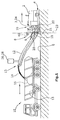
- Fig. 1 shows the example of a back-loader milling machine 1b, in which the transport vehicle 10 travels behind in reverse drive behind the milling machine.
- the transport vehicle 10 can also be moved in forward motion next to the milling machine 1.
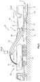
- Fig. 2 shows a milling machine using the example of a front-end road milling machine 1a.
- the road construction machine 1 has a machine frame 2, which is supported by an existing example of crawler tracks or wheels chassis 4, which is connected via at least three height adjustment devices in the form of lifting columns 5 with the machine frame 2.
- four lifting columns 5 are provided, with which the machine frame 2 can be brought into a predetermined plane, which preferably runs parallel to the road surface 6, on which the crawler tracks of the chassis 4 are.
- Fig. 2 Road milling machine has a work roll 22 in the longitudinal direction of the milling machine 1a between the crawler tracks of the chassis 4.
- the work roll can be height-adjustable via the lifting frame 5 carrying the machine frame 2 or relative to the machine frame 2.
- the milling machines 1a, 1b may have crawler tracks and / or wheels.
- the milling machines 1a, 1b may have a single steerable axle as a steerable axle, or a steerable front axle in combination with at least one rear steerable wheel or track drive.
- a conveyor belt device with at least one conveyor belt 11, 12 for removal of the milled milled material at the front 7 or rear end 8 of the milling machine 1a, 1b may be arranged.
- the milled material milled by the work roll 22 is loaded onto the loading surface 15 of the transport vehicle 10 via a first stationary conveyor belt 11 of the conveyor belt device, which transfers the milled material 14 to a second pivotable conveyor belt 12. Due to the speed of the conveyor belt 12 of the conveyor belt device, the milled material 14 is not unloaded directly at the end of the conveyor belt 12, but the milled material follows a throw parabola, so that the point of impact 16 is located on the bed 15 at a distance from the free end 13 of the conveyor belt 12.
- the conveyor belt 12 can be pivoted from a central position to the left or to the right via piston-cylinder units 18 to dump the material to be milled 14 even when cornering or when tracked driving the transport vehicle 10 on the bed 15 or to the milling machine during conversion maneuvering to another place better. Furthermore, the operator of the milling machine 1a, 1b adjust the elevation angle of the conveyor belt 12 by means of a piston-cylinder unit 20. The elevation angle as well as the conveying speed of the conveyor belt 12, the parabolas of the milled material 14 and the position of the impact point 16 are influenced.
- the currently set elevation angle about a horizontal axis 21 or pivot angle about a vertical axis 23 and the current steering angle is reported to a detection and control system 24, which may further comprise at least one detector 26, the position of the loading surface 15 and / or of the transport direction last or single conveyor belt 12 of the conveyor belt device continuously detected.
- This detector 26 can either be arranged on the milling machine 1a, 1b at the end facing the conveyor belt 12 or at the free end 13 of the conveyor belt 12.
- the detection and control system 24 may be integrated into the operator-operated control 3 for the driving, steering and milling operation or at least connected to it, possibly also data on the driving speed, the distance covered and / or a detected steering angle the milling machine 1a, 1b and the conveying speed of the conveyor belt 12 to obtain.
- the controller 3 has a detection and control system 24 which detects the steering angle of the steering control for the chassis and automatically controls the pivot angle of the conveyor belt 12 in response to this parameter.
- the steering angle of the steering control and the distance traveled can be detected and controlled in dependence of these parameters, the pivot angle of the conveyor belt 12 automatically.
- the driving speed can be detected and the traveled distance can be calculated from the driving speed.
- Another possibility is to make a change in the swivel angle corresponding to the steering angle only when a minimum speed is exceeded.
- the pivot angle of the conveyor belt 12 thus follows the currently set or the average set over a certain distance traveled steering angle, which can be detected, for example, characterized in that the current steering angle z. B. is permanently detected at the wheels or crawler tracks of the front axle of the chassis or is taken directly from the steering control.
- the detection and control system 24 automatically control the pivoting angle of the conveyor belt 12 in such a way that the pivotable conveyor belt 12 assumes a pivoting angle calculated and predetermined by the control in each steering position during forward or reverse travel.
- the fictional trailer is provided with a wheel axle, which forms a center of rotation.
- the position of the center of rotation can be chosen freely, preferably in the range between one third and the entire length of the pivotable conveyor belt 12, or between one third and the entire length up to the point of impact 16 on a loading surface 15 of the transport vehicle.
- the detection and control system 24 can automatically control the pivoting angle of the conveyor belt 12 continuously such that the pivotable conveyor belt 12 in each steering position during forward or reverse travel assumes a pivot angle at which the end of the conveyor belt 12 or alternatively the point of impact 16 is guided on the loading surface 15 substantially along the center line 34 of the lane 32 which has already been driven over or is still to be driven over.
- the end of the conveyor belt 12 may also be guided along an equidistant to the center line 34 of the lane 32 already crossed or still to be driven over, namely when a transport vehicle 10 is moved next to the lane 32.
- the detection and control system 24 may have a distance measuring device 40, with which the distance to a following in the conveying direction of the conveyor belt 12 transport vehicle 10 is detectable. It can the detection and control system 24 for the driver of the transport vehicle 10 detectable, preferably visible start / stop signals generate.
- a programmable or teach-in readable distance range can be entered into the detection and control system 24 that is shorter than the maximum length of the loading surface 15 of the respective transport vehicle 10.
- the starting distance may depend on the measured distance. or stop signal is displayed.
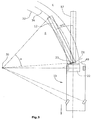
- Fig. 3 shows a milling machine 1b according to Fig. 1 when cornering along a center line 34 of a lane 32.
- the conveyor belt 12 takes the position shown in dashed lines. It is understood that when starting from such a straight ahead cornering about a center of rotation 36 is initiated, the conveyor belt 12 would far out without a pivot angle control and on the one hand at a displacement of the milling machine with obstacles, such. As masts or traffic lights, could collide on the roadside, or could not unload in milling operation to a desired point of impact 16 on the bed of a transport vehicle 15 if the tilt angle would not be corrected.
- the conveyor belt 12 with a solid line shows the situation with an automatic swivel angle control, in which the free end of the conveyor belt 12 is guided along the center line 34.
- the calculation of the swivel angle by the controller 3, however, can also be such that the free end of the conveyor belt 12 can also follow an equidistant to the center line 34 of the lane 32, for example, to load a moving next to the lane 32 transport vehicle 10 can.
- the detection and control system 24 can also locate the variable position of the loading surface 15 of the transport vehicle 10 and the transport belt in the last or single conveyor belt 12 of the conveyor belt relative to the machine frame 2 and the positioning of the impact point 16 of the material to be milled 14 on the elevation angle and / or the conveying speed the conveyor belt device continuously and automatically control, so that the discarded Milling material 14 strikes at least within the loading area 15.
- the variable position of the loading area 15 of the transport vehicle 10 relative to the transport direction in the last or single conveyor belt 12 can be continuously located to perform the control.
- the detection and control system 24 can continuously detect the position of the loading area 15 and / or the last or single conveyor belt 12 in the transport direction with the aid of an image acquisition system 28 or a non-optical electronic location system, the data for determining the position of the loading area 15 in relation to the machine frame 2 or to the last or single conveyor belt 12 in the transport direction.
- the information of the image acquisition system 28 can be evaluated by known image analysis methods.
- An example of a non-optical electronic positioning system is a radio-frequency identification system (RFID), which additionally allows the possibility of identifying a specific loading area 15 of a specific transport vehicle 10.
- RFID radio-frequency identification system
- stationary RFID tags can be used on the transport vehicle 10, in particular on the loading surface 15.
- sensor nodes distributed in space are used as markers and the signal field strength, which is dependent on the distance, is measured.
- the distance measurement can be realized with the above measuring method, or with conventional measuring methods such. B. by means of ultrasound.
- the desired position data can be determined by a teach-in method by varying the positions of the vehicles 1a, 1b, 10 in accordance with realistic situations and storing the respectively required parameters, namely elevation angle and conveying speed of the conveyor belt 12. In the same way, a loading program can be created. It also variations of the control, z. B. caused by cornering, are taken into account.
- the read by the reading data can also distinguish whether the transport vehicle 10 is left or right next to the milling track 32 or in the milling track 32 of the milling machine 1a, 1b.
Landscapes
- Engineering & Computer Science (AREA)
- Mining & Mineral Resources (AREA)
- Mechanical Engineering (AREA)
- Architecture (AREA)
- Civil Engineering (AREA)
- Structural Engineering (AREA)
- Life Sciences & Earth Sciences (AREA)
- General Life Sciences & Earth Sciences (AREA)
- Geochemistry & Mineralogy (AREA)
- Geology (AREA)
- Control Of Position, Course, Altitude, Or Attitude Of Moving Bodies (AREA)
- Road Repair (AREA)
Claims (15)
- Fraiseuse automotrice (1a, 1b), en particulier engin de fraisage routier ou engin pour mine à ciel ouvert, comprenant- un châssis (2) ayant un axe longitudinal,- un mécanisme de roulement équipé de roues ou de chenilles, qui supportent le châssis (2),- un dispositif de commande (3) destiné à la conduite, à la direction et au fraisage,- un rouleau de travail (22) réglable en hauteur,- une dernière ou unique bande transporteuse pivotante (12) de longueur prédéterminée disposée en amont ou en aval du rouleau de travail (22) par référence au sens de roulement de la fraiseuse (1a, 1b),- la bande transporteuse (12) pouvant pivoter latéralement avec un angle de pivotement au moins autour d'un premier axe (23) orienté sensiblement verticalement,caractérisé en ce que
le dispositif de commande (3) comprend un système de détection et de commande (24) qui détecte au moins l'angle de direction de la commande de direction du mécanisme de roulement, ou au moins l'angle de direction de la commande de direction et la distance parcourue ou l'angle de direction de la commande de direction et la vitesse de roulement et qui commande l'angle de pivotement de la bande transporteuse (12) en fonction de cet au moins un paramètre ou ensemble de paramètres. - Dispositif selon la revendication 1, caractérisé en ce que le système de détection et de commande commande automatiquement en continu l'angle de pivotement de la bande transporteuse (12) de telle sorte que la bande transporteuse pivotante (12) occupe dans chaque situation de direction pour marche avant ou arrière un angle de pivotement qui correspond en marche avant sensiblement à l'angle de pivotement de l'axe longitudinal d'une remorque fictive pivotante à un seul essieu qui est articulée au niveau d'un premier axe (23).
- Dispositif selon la revendication 1 ou 2, caractérisé en ce que le système de détection et de commande définit un angle de pivotement de la bande transporteuse pivotante (12) qui correspond en marche avant sensiblement à l'angle de pivotement de l'axe longitudinal d'une remorque fictive articulée au niveau du premier axe (23), la position du centre de rotation autour de l'axe de la remorque fictive dans direction longitudinale pouvant être choisie.
- Dispositif selon la revendication 3, caractérisé en ce que le centre de rotation se trouve à une distance du premier axe (23) dans la gamme comprise entre un tiers et la longueur totale de la bande transporteuse pivotante (12) ou de la longueur jusqu'au point de décharge (16), de préférence dans la gamme comprise entre 40% et 60% de la longueur totale.
- Dispositif selon l'une des revendications 1 à 4, caractérisé en ce que le système de détection et de commande commande automatiquement en continu l'angle de pivotement de la bande transporteuse pivotante (12) de telle sorte que la bande transporteuse pivotante (12) occupe dans chaque situation de direction en marche avant ou arrière un angle de pivotement prédéterminé pour lequel l'extrémité de la bande transporteuse (12) est guidée sensiblement le long de la ligne médiane (34) ou à équidistance de la ligne médiane (34) du chemin de roulement (32) déjà parcouru ou encore à parcourir.
- Dispositif selon l'une des revendications 1 à 5, caractérisé en ce que la bande transporteuse (12) est apte à pivoter avec un angle de hauteur prédéterminé autour d'un second axe (21) orthogonal au premier axe (23),
la bande transporteuse (12) déchargeant le matériau fraisé (14) à une vitesse de transport prédéterminée sur une surface de chargement (15) d'un véhicule de transport (10), et
le système de détection et de commande (24) détectant en continu la position de la surface de chargement (15) et/ou de la bande transporteuse (12), et effectuant une commande en continu de l'angle de hauteur de la bande transporteuse (12) et/ou une commande en continu de la vitesse de transport pour maintenir un point d'impact (16) sur la surface de chargement (15) toujours à l'intérieur de la zone de chargement (15) ou au moins le long du plan médian longitudinal de la surface de chargement (15) ou le long de la ligne médiane (34) au milieu du chemin de roulement (32) déjà parcouru ou encore à parcourir. - Dispositif selon l'une des revendications 1 à 6, caractérisé en ce que le système de détection et de commande (24) comprend au moins un détecteur qui détecte directement ou indirectement l'angle de direction prédéterminé de la commande de direction du mécanisme de roulement ou l'angle de direction et la distance parcourue ou la vitesse de roulement et d'autres détecteurs qui détectent directement ou indirectement l'angle de pivotement actuel et l'angle de hauteur.
- Procédé de direction d'une fraiseuse automotrice (1a, 1b), et en particulier un engin de fraisage routier ou engin pour mine à ciel ouvert, le long d'un chemin de roulement prédéterminé, dans lequel- le roulement, la direction, et le fraisage sont commandés par un dispositif de commande (3),- la fraiseuse (1a, 1b) est supportée par un mécanisme de roulement orientable à roues ou à chenilles,- le matériau fraisé (14) retiré par un rouleau de travail (22) pendant le fraisage est transporté par une bande transporteuse (12) disposée en amont ou en aval de la fraiseuse (1a, 1b) par référence au sens de roulement de la fraiseuse (1a, 1b), et- une dernière ou unique bande transporteuse (12) pouvant être pivotée au moins latéralement avec un angle de pivotement autour d'un premier axe (23) orienté sensiblement verticalement,caractérisé en ce que
au moins l'angle de direction de la commande de direction du mécanisme de roulement, ou au moins l'angle de direction de la commande de direction et la distance parcourue ou l'angle de direction de la commande de direction et la vitesse de roulement sont détectés et l'angle de pivotement de la bande transporteuse (12) est commandé en fonction de cet au moins un paramètre ou ensemble de paramètres. - Procédé selon la revendication 8, caractérisé en ce que l'angle de pivotement de la bande transporteuse (12) est commandé automatiquement en continu, en ce que la bande transporteuse pivotante (12) occupe dans chaque situation de direction en marche avant ou arrière un angle de pivotement qui correspond en marche avant sensiblement à l'angle de pivotement de l'axe longitudinal d'une remorque fictive pivotante à un seul essieu articulée au niveau du premier axe (23).
- Procédé selon la revendication 8 ou 9, caractérisé en ce que l'angle de pivotement de la bande transporteuse pivotante (12) est commandé automatiquement en continu, en ce que l'angle de pivotement prédéterminé correspondant en marche avant sensiblement à l'angle de pivotement de l'axe longitudinal d'une remorque fictive pivotante sur le premier axe (23), la position du centre de rotation de la remorque fictive le long de l'axe longitudinal de la bande transporteuse pouvant être choisi librement pour calculer et ajuster l'angle de pivotement.
- Procédé selon l'une des revendications 8 à 10, caractérisé en ce que l'angle de pivotement de la bande transporteuse pivotante (12) est commandé automatiquement en continu, en ce que la bande transporteuse pivotante (12) occupe dans chaque situation de direction en marche avant ou arrière un angle de pivotement prédéterminé pour lequel l'extrémité de la bande transporteuse (12) est guidée sensiblement le long de la ligne médiane (34) ou à équidistance de la ligne médiane (34) du chemin de roulement (32) parcouru ou à parcourir.
- Procédé selon l'une des revendications 8 à 11, caractérisé en ce que le matériau fraisé (14) est déchargé sur une surface de chargement (15) d'un véhicule de transport (10) à une vitesse de transport prédéterminée et à un angle de hauteur prédéterminé autour d'un second axe (21) orthogonal au premier axe (23) et l'angle de hauteur et/ou la vitesse de transport de la bande transporteuse (12) sont commandés automatiquement en continu de telle sorte que le matériau fraisé (14) est déchargé dans la surface de chargement (15) ou au moins le long d'un plan médian longitudinal de la surface de chargement (15) ou le long de la ligne médiane (34) du chemin de roulement (32) déjà parcouru ou à parcourir.
- Procédé selon la revendication 12, caractérisé en ce que la surface de chargement (15) est détectée et l'angle de hauteur et/ou la vitesse de transport de la bande transporteuse (12) peuvent être régulés de telle sorte que le point d'impact (16) sur la surface de chargement (15) est conservé également dans une marche en courbe le long du plan médian longitudinal de la surface de chargement (15) ou sur la ligne médiane (34) du chemin de roulement (32).
- Procédé selon l'une des revendications 8 à 13, caractérisé en ce que la distance par rapport à un véhicule de transport (10) en arrière par référence à la direction de transport de la bande transporteuse (12) est détectée, des signaux de démarrage/d'arrêt du véhicule de transport (10), de préférence visibles, reconnaissable par le conducteur du véhicule de transport (10), étant générés en fonction du signal de distance.
- Procédé selon la revendication 14, caractérisé en ce que l'on entre une zone de distance, programmable ou lisible par apprentissage, qui est plus courte que la longueur maximale d'une surface de chargement (15) du véhicule de transport (10) respectif, le signal de démarrage ou d'arrêt étant déclenché en fonction de la distance mesurée lorsque l'on sorte de la zone de distance prédéterminée.
Applications Claiming Priority (1)
| Application Number | Priority Date | Filing Date | Title |
|---|---|---|---|
| DE102012215005.6A DE102012215005A1 (de) | 2012-08-23 | 2012-08-23 | Selbstfahrende Fräsmaschine, sowie Verfahren zum Lenken einer selbstfahrenden Fräsmaschine |
Publications (2)
| Publication Number | Publication Date |
|---|---|
| EP2700748A1 EP2700748A1 (fr) | 2014-02-26 |
| EP2700748B1 true EP2700748B1 (fr) | 2016-03-16 |
Family
ID=49028941
Family Applications (1)
| Application Number | Title | Priority Date | Filing Date |
|---|---|---|---|
| EP13181254.7A Active EP2700748B1 (fr) | 2012-08-23 | 2013-08-21 | Fraiseuse automotrice et procédé de conduite d'une fraiseuse automotrice |
Country Status (4)
| Country | Link |
|---|---|
| US (3) | US9234319B2 (fr) |
| EP (1) | EP2700748B1 (fr) |
| CN (2) | CN103628397B (fr) |
| DE (1) | DE102012215005A1 (fr) |
Families Citing this family (26)
| Publication number | Priority date | Publication date | Assignee | Title |
|---|---|---|---|---|
| DE102009041842A1 (de) | 2009-09-18 | 2011-09-01 | Wirtgen Gmbh | Selbstfahrende Straßenfräsmaschine |
| DE102013009361B4 (de) * | 2013-06-04 | 2018-07-12 | Bomag Gmbh | Bodenfräsmaschine mit einer Anbauförderbandsteuerung, Anbauförderbandsteuerung für eine Bodenfräsmaschine sowie Verfahren zur Steuerung eines Anbauförderbandes einer Bodenfräsmaschine |
| FR3010805A1 (fr) * | 2013-09-13 | 2015-03-20 | Airbus Operations Sas | Procede et dispositif d'aide au pilotage d'un aeronef lors d'un vol parabolique en vue de generer une impesanteur dans l'aeronef. |
| DE102014216603B4 (de) * | 2014-08-21 | 2018-02-22 | Wirtgen Gmbh | Selbstfahrende Fräsmaschine, sowie Verfahren zum Abladen von Fräsgut |
| DE102014216713B4 (de) | 2014-08-22 | 2018-09-06 | Wirtgen Gmbh | Selbstfahrende Fräsmaschine, sowie Verfahren zum Abladen von Fräsgut |
| DE102014216763B4 (de) | 2014-08-22 | 2018-07-26 | Wirtgen Gmbh | Selbstfahrende Fräsmaschine, sowie Verfahren zum Abladen von Fräsgut |
| US9464391B2 (en) * | 2014-08-29 | 2016-10-11 | Caterpillar Paving Products Inc. | Cold planer having independently controlled conveyors |
| US10380529B2 (en) * | 2015-08-17 | 2019-08-13 | Caterpillar Paving Products Inc. | Cold planer material transport management system |
| CN105386399B (zh) * | 2015-10-13 | 2018-03-09 | 长安大学 | 一种路面铣刨机及铣刨平整度辅助控制方法 |
| US20170130405A1 (en) * | 2015-11-05 | 2017-05-11 | Caterpillar Paving Products Inc. | Truck position control system for milling operations |
| CN108473260B (zh) | 2016-01-21 | 2022-08-12 | 维特根有限公司 | 包括建筑机械、具有装载空间的运输车辆和图像记录装置的系统以及用于在运输车辆的装载或卸载期间显示图像流的方法 |
| DE102016222145A1 (de) | 2016-11-11 | 2018-05-17 | Wirtgen Gmbh | System und Verfahren zum Nachverfolgen von Fräsgut |
| DE102016223454A1 (de) | 2016-11-25 | 2018-05-30 | Wirtgen Gmbh | System und Verfahren zum Nachverfolgen von Fräsgut |
| US10927513B2 (en) | 2016-11-11 | 2021-02-23 | Wirtgen Gmbh | System and method for the tracking of milling material |
| DE102016222589B4 (de) * | 2016-11-16 | 2020-01-16 | Wirtgen Gmbh | Selbstfahrende Fräsmaschine, sowie Verfahren zum Steuern einer selbstfahrenden Fräsmaschine |
| DE102017220869A1 (de) * | 2017-11-22 | 2019-05-23 | Wirtgen Gmbh | Selbstfahrende Fräsmaschine, Verfahren zum automatischen Beladen eines Transportmittels mit Fräsgut, sowie Straßen- oder Bodenbearbeitungseinheit |
| CN108278981A (zh) * | 2018-02-11 | 2018-07-13 | 北京主线科技有限公司 | 检测无人驾驶挂车轴偏角的装置及其检测方法 |
| CN108221610A (zh) * | 2018-03-14 | 2018-06-29 | 徐州徐工筑路机械有限公司 | 一种基于视觉识别的铣刨机自动输料系统 |
| DE102018119962A1 (de) * | 2018-08-16 | 2020-02-20 | Wirtgen Gmbh | Selbstfahrende Baumaschine und Verfahren zum Steuern einer selbstfahrenden Baumaschine |
| DE102019104218A1 (de) | 2019-02-19 | 2020-08-20 | Wirtgen Gmbh | Arbeitszug, umfassend eine Bodenbearbeitungsmaschine und ein weiteres Fahrzeug sowie eine automatisierte Abstandsüberwachung |
| US10982397B2 (en) * | 2019-06-12 | 2021-04-20 | Caterpillar Paving Products Inc. | Milling rotor |
| CN111926666A (zh) * | 2020-07-02 | 2020-11-13 | 丁丽丽 | 一种市政工程用沥青路面高效修补装置 |
| CN112065384B (zh) * | 2020-09-02 | 2022-05-17 | 山东中煤工矿物资集团有限公司 | 一种具有挖掘功能的载具设备 |
| EP4298298A1 (fr) | 2021-02-23 | 2024-01-03 | Ligchine International Corporation | Appareil de lissage de béton à flèche pivotante |
| CN114455249A (zh) * | 2022-01-05 | 2022-05-10 | 中国电建集团华东勘测设计研究院有限公司 | 一种长距离大运量空间曲线带式输送机的布置方法 |
| CN114808632A (zh) * | 2022-06-06 | 2022-07-29 | 福建兴翼机械有限公司 | 一种智能化抛丸机及其控制方法 |
Citations (1)
| Publication number | Priority date | Publication date | Assignee | Title |
|---|---|---|---|---|
| EP2573266A2 (fr) * | 2011-09-22 | 2013-03-27 | BOMAG GmbH | Procédé de commande d'un procédé de chargement d'un véhicule de transport avec des produits de fraisage, dispositif destiné à réaliser un tel procédé et dispositif de fraisage |
Family Cites Families (34)
| Publication number | Priority date | Publication date | Assignee | Title |
|---|---|---|---|---|
| US3608968A (en) | 1969-04-03 | 1971-09-28 | Christensen Diamond Prod Co | Pavement cutting and water and cutting pickup apparatus |
| US4376609A (en) * | 1980-03-31 | 1983-03-15 | Sperry Corporation | Automatic spout control for agricultural machines |
| DD155157A1 (de) | 1980-12-09 | 1982-05-19 | Bernd Kaempfe | Positioniereinrichtung,insbesondere zwischen erntemaschinen und transportfahrzeugen |
| US4863009A (en) | 1988-11-14 | 1989-09-05 | Alberta Energy Company Ltd. | Control system for an endless belt conveyor train |
| DE4403893A1 (de) | 1994-02-08 | 1995-08-10 | Claas Ohg | Vorrichtung zur automatischen Befüllung von Ladebehältern mit einem Gutstrom |
| DE19628420C2 (de) | 1996-07-15 | 1999-07-29 | Krupp Foerdertechnik Gmbh | Verfahren zum Materialabbau mittels eines Schaufelradbaggers |
| DE69908526T2 (de) | 1998-04-03 | 2004-05-06 | Koninklijke Philips Electronics N.V. | Verfahren und System zur Bildverarbeitung unter Verwendung von Konturerfassungsschritten |
| DE19848127A1 (de) * | 1998-10-19 | 2000-04-20 | Claas Selbstfahr Erntemasch | Vorrichtung zur Steuerung einer Überladeeinrichtung |
| US6682416B2 (en) * | 2000-12-23 | 2004-01-27 | Claas Selbstfahrende Erntemaschinen Gmbh | Automatic adjustment of a transfer device on an agricultural harvesting machine |
| DE10203732A1 (de) | 2002-01-30 | 2003-08-21 | Wirtgen Gmbh | Baumaschine |
| US6943824B2 (en) * | 2002-03-13 | 2005-09-13 | Deere & Company | Image processing spout control system |
| DE10223819B4 (de) * | 2002-05-28 | 2005-05-12 | Wirtgen Gmbh | Fräsmaschine zum Bearbeiten von Bodenoberflächen, sowie Verfahren zum Entsorgen von während der Fräsbearbeitung entstehenden Stäuben und Dämpfen an einer Fräsmaschine |
| CN1209530C (zh) * | 2003-05-16 | 2005-07-06 | 长沙中联重工科技发展股份有限公司 | 可实现铣刨机排料速度自适应控制的方法及装置 |
| DE10357074B3 (de) * | 2003-12-04 | 2005-05-19 | Wirtgen Gmbh | Selbstfahrende Maschine zum Herstellen von Fahrbahnen |
| CN2697144Y (zh) * | 2004-02-10 | 2005-05-04 | 三一重工股份有限公司 | 转运车电视监控装置 |
| DE102004007716B3 (de) * | 2004-02-16 | 2005-06-16 | Wirtgen Gmbh | Fräsmaschine sowie Verfahren zum Bearbeiten von Bodenoberflächen |
| DE102004011789A1 (de) | 2004-03-09 | 2005-09-29 | Claas Selbstfahrende Erntemaschinen Gmbh | Vorrichtung zum Erfassen eines Ladewagens |
| US20060045621A1 (en) | 2004-08-27 | 2006-03-02 | Caterpillar Paving Products Inc. | Asphalt-removing work machine having a storage bin |
| DE102005035480A1 (de) | 2005-07-26 | 2007-02-01 | Cft Gmbh Compact Filter Technic | Fräsmaschine für Straßenbeläge mit Entstaubung |
| FI120191B (fi) | 2005-10-03 | 2009-07-31 | Sandvik Tamrock Oy | Menetelmä kaivosajoneuvojen ajamiseksi kaivoksessa ja kuljetusjärjestelmä |
| DE102007009666A1 (de) | 2007-02-22 | 2008-08-28 | Carl Zeiss Microimaging Gmbh | Anordnung zum Befüllen eines Behälters mit Schüttgut |
| DE112008000646T5 (de) | 2007-03-20 | 2010-05-12 | Volvo Construction Equipment Ab | Fräsmaschine mit Schneidtrommel-Geschwindigkeitssteuerung |
| DE202007005756U1 (de) * | 2007-04-19 | 2008-08-28 | Wirtgen Gmbh | Selbstfahrende Baumaschine |
| EP2020174B1 (fr) * | 2007-08-03 | 2012-02-29 | AGROCOM GmbH & Co. Agrarsystem KG | Machine de travail agricole |
| DE102008008260B4 (de) | 2008-02-08 | 2010-09-09 | Wirtgen Gmbh | Steuerung einer Gewinnungsmaschine und Gewinnungsmaschine |
| DE102008014001A1 (de) | 2008-03-13 | 2009-09-17 | Claas Selbstfahrende Erntemaschinen Gmbh | Landwirtschaftliche Erntemaschine mit einer Überladeeinrichtung |
| CN102015417B (zh) * | 2008-04-25 | 2013-02-27 | 株式会社小松制作所 | 作业车辆的转向控制装置及转向控制方法 |
| DE102008021484B4 (de) * | 2008-04-29 | 2010-01-28 | Wirtgen Gmbh | Knickbares Transportband für eine Baumaschine, selbstfahrende Baumaschine und Verfahren zum Verschwenken eines Transportbandes |
| PL2256246T3 (pl) | 2009-05-20 | 2018-11-30 | Joseph Vögele AG | Ciąg do tworzenia nawierzchni drogowej dla utworzenia nawierzchni drogowej |
| EP2311307B1 (fr) | 2009-09-07 | 2011-12-07 | CLAAS Agrosystems GmbH & Co. KG | Jauge de remplissage, véhicule agricole doté d'une telle jauge et procédé de commande de remplissage d'une région cible |
| ATE533350T1 (de) | 2009-09-07 | 2011-12-15 | Claas Agrosystems Gmbh & Co Kg | Steuerungssystem eines landwirtschaftlichen fahrzeugs mit einem güterträger, landwirtschaftliches fahrzeug und verfahren zur steuerung eines güterträgers des landwirtschaftlichen fahrzeugs |
| DE102009041842A1 (de) | 2009-09-18 | 2011-09-01 | Wirtgen Gmbh | Selbstfahrende Straßenfräsmaschine |
| DE102010043854B4 (de) | 2010-11-12 | 2016-01-14 | Deere & Company | Steueranordnung zur Kontrolle des Überladens landwirtschaftlichen Ernteguts von einer Erntemaschine auf ein Transportfahrzeug |
| DE102011114185A1 (de) | 2011-09-22 | 2013-03-28 | Bomag Gmbh | Arbeitszug mit einer Fräsvorrichtung und einer Transporteinrichtung mit einer Sensoreinrichtung zur Abstandsüberwachung, Fräsvorrichtung mit einer Sensoreinrichtung und Verfahren zur Abstandsüberwachung bei einem Arbeitszug |
-
2012
- 2012-08-23 DE DE102012215005.6A patent/DE102012215005A1/de not_active Withdrawn
-
2013
- 2013-08-13 US US13/965,936 patent/US9234319B2/en active Active
- 2013-08-21 EP EP13181254.7A patent/EP2700748B1/fr active Active
- 2013-08-23 CN CN201310373198.3A patent/CN103628397B/zh active Active
- 2013-08-23 CN CN201320520735.8U patent/CN203654144U/zh not_active Expired - Lifetime
-
2016
- 2016-01-05 US US14/987,811 patent/US9873993B2/en active Active
-
2018
- 2018-01-16 US US15/872,160 patent/US10378163B2/en active Active
Patent Citations (1)
| Publication number | Priority date | Publication date | Assignee | Title |
|---|---|---|---|---|
| EP2573266A2 (fr) * | 2011-09-22 | 2013-03-27 | BOMAG GmbH | Procédé de commande d'un procédé de chargement d'un véhicule de transport avec des produits de fraisage, dispositif destiné à réaliser un tel procédé et dispositif de fraisage |
Also Published As
| Publication number | Publication date |
|---|---|
| DE102012215005A1 (de) | 2014-02-27 |
| CN203654144U (zh) | 2014-06-18 |
| US20160194840A1 (en) | 2016-07-07 |
| US20180202116A1 (en) | 2018-07-19 |
| US10378163B2 (en) | 2019-08-13 |
| EP2700748A1 (fr) | 2014-02-26 |
| US20140054949A1 (en) | 2014-02-27 |
| CN103628397A (zh) | 2014-03-12 |
| US9234319B2 (en) | 2016-01-12 |
| CN103628397B (zh) | 2017-04-12 |
| US9873993B2 (en) | 2018-01-23 |
Similar Documents
| Publication | Publication Date | Title |
|---|---|---|
| EP2700748B1 (fr) | Fraiseuse automotrice et procédé de conduite d'une fraiseuse automotrice | |
| EP2888409B1 (fr) | Fraiseuse automotrice et procédé de déversement de fraisat | |
| EP2987911B1 (fr) | Fraiseuse automobile, et procede d'evacuation de produit de fraisage | |
| EP2987912B1 (fr) | Fraiseuse automobile, et procédé d'évacuation de produit de fraisage | |
| EP3323940B1 (fr) | Fraiseuse automotrice et procédé de commande d'une fraiseuse automotrice | |
| EP2621257B1 (fr) | Combinaison constituée d'un véhicule tracteur et d'un appareil | |
| EP2987910B1 (fr) | Fraiseuse automotrice, et procédé d'évacuation de produit de fraisage | |
| EP3255973B1 (fr) | Dispositif d'épandage de liquides et procédé pour le contrôle du mouvement d'au moins deux bras d'extension d'un pulvérisateur agricole | |
| DE102016011324A1 (de) | Verfahren zur Steuerung eines Zugfahrzeugs bei dessen Heranfahren und Ankuppeln an ein Anhängerfahrzeug | |
| DE102008043675A1 (de) | Verfahren und Steuergerät zur Bestimmung von Soll-Lenkwinkel eines mehrgliedrigen Fahrzeuggespanns | |
| DE112013001746T5 (de) | Steuerung für Kurvenfahrtoperationen eines Motorgraders | |
| EP2042352B1 (fr) | Dispositif et procédé d'accouplement d'une remorque sur un véhicule de traction agricole | |
| EP3135823A1 (fr) | Engin automobile et procede d'affichage de l'environnement d'un engin automobile | |
| DE102013006464A1 (de) | Baumaschine mit einer Manövriereinrichtung, Verfahren zur Erleichterung des Manövrierens einer Baumaschine und Manövriereinrichtung für eine Baumaschine | |
| DE102019211708A1 (de) | Vorwärts gerichteter sensor zur vorausschauenden nivellierungssteuerung | |
| EP3401442A1 (fr) | Finisseuse de route ayant une compensation de braquage et procédé de commande | |
| EP1488676B1 (fr) | Moissonneuse automotrice | |
| DE102016222549B4 (de) | Verfahren zum Ermitteln einer Anhängerinformation und Kraftfahrzeug | |
| DE102018105536A1 (de) | Gleitschalungsfertiger und Verfahren zum Betreiben eines Gleitschalungsfertigers | |
| EP3489415B1 (fr) | Machine de fraisage autopropulsée et procédé de chargement automatique d'un moyen de transport avec du matériau fraisé | |
| EP3469899A1 (fr) | Machine d'épandage agricole et procédé de commande d'une telle machine d'épandage | |
| EP4368481A1 (fr) | Fraiseuse routière, en particulier fraiseuse routière, stabilisateur ou recycle, procédé de conduite d'une fraiseuse routière vers une direction à 90° vers une direction de machine et procédé de positionnement | |
| WO2014166827A2 (fr) | Tunnelier et procédé de déplacement d'un tunnelier |
Legal Events
| Date | Code | Title | Description |
|---|---|---|---|
| PUAI | Public reference made under article 153(3) epc to a published international application that has entered the european phase |
Free format text: ORIGINAL CODE: 0009012 |
|
| AK | Designated contracting states |
Kind code of ref document: A1 Designated state(s): AL AT BE BG CH CY CZ DE DK EE ES FI FR GB GR HR HU IE IS IT LI LT LU LV MC MK MT NL NO PL PT RO RS SE SI SK SM TR |
|
| AX | Request for extension of the european patent |
Extension state: BA ME |
|
| 17P | Request for examination filed |
Effective date: 20140816 |
|
| RBV | Designated contracting states (corrected) |
Designated state(s): AL AT BE BG CH CY CZ DE DK EE ES FI FR GB GR HR HU IE IS IT LI LT LU LV MC MK MT NL NO PL PT RO RS SE SI SK SM TR |
|
| 17Q | First examination report despatched |
Effective date: 20141222 |
|
| GRAP | Despatch of communication of intention to grant a patent |
Free format text: ORIGINAL CODE: EPIDOSNIGR1 |
|
| INTG | Intention to grant announced |
Effective date: 20150907 |
|
| GRAS | Grant fee paid |
Free format text: ORIGINAL CODE: EPIDOSNIGR3 |
|
| GRAA | (expected) grant |
Free format text: ORIGINAL CODE: 0009210 |
|
| AK | Designated contracting states |
Kind code of ref document: B1 Designated state(s): AL AT BE BG CH CY CZ DE DK EE ES FI FR GB GR HR HU IE IS IT LI LT LU LV MC MK MT NL NO PL PT RO RS SE SI SK SM TR |
|
| REG | Reference to a national code |
Ref country code: GB Ref legal event code: FG4D Free format text: NOT ENGLISH |
|
| REG | Reference to a national code |
Ref country code: CH Ref legal event code: EP |
|
| REG | Reference to a national code |
Ref country code: IE Ref legal event code: FG4D Free format text: LANGUAGE OF EP DOCUMENT: GERMAN |
|
| REG | Reference to a national code |
Ref country code: AT Ref legal event code: REF Ref document number: 781385 Country of ref document: AT Kind code of ref document: T Effective date: 20160415 |
|
| REG | Reference to a national code |
Ref country code: DE Ref legal event code: R096 Ref document number: 502013002178 Country of ref document: DE |
|
| REG | Reference to a national code |
Ref country code: SE Ref legal event code: TRGR |
|
| REG | Reference to a national code |
Ref country code: NL Ref legal event code: MP Effective date: 20160316 |
|
| REG | Reference to a national code |
Ref country code: LT Ref legal event code: MG4D |
|
| PG25 | Lapsed in a contracting state [announced via postgrant information from national office to epo] |
Ref country code: NO Free format text: LAPSE BECAUSE OF FAILURE TO SUBMIT A TRANSLATION OF THE DESCRIPTION OR TO PAY THE FEE WITHIN THE PRESCRIBED TIME-LIMIT Effective date: 20160616 Ref country code: HR Free format text: LAPSE BECAUSE OF FAILURE TO SUBMIT A TRANSLATION OF THE DESCRIPTION OR TO PAY THE FEE WITHIN THE PRESCRIBED TIME-LIMIT Effective date: 20160316 Ref country code: GR Free format text: LAPSE BECAUSE OF FAILURE TO SUBMIT A TRANSLATION OF THE DESCRIPTION OR TO PAY THE FEE WITHIN THE PRESCRIBED TIME-LIMIT Effective date: 20160617 Ref country code: FI Free format text: LAPSE BECAUSE OF FAILURE TO SUBMIT A TRANSLATION OF THE DESCRIPTION OR TO PAY THE FEE WITHIN THE PRESCRIBED TIME-LIMIT Effective date: 20160316 |
|
| REG | Reference to a national code |
Ref country code: FR Ref legal event code: PLFP Year of fee payment: 4 |
|
| PG25 | Lapsed in a contracting state [announced via postgrant information from national office to epo] |
Ref country code: LT Free format text: LAPSE BECAUSE OF FAILURE TO SUBMIT A TRANSLATION OF THE DESCRIPTION OR TO PAY THE FEE WITHIN THE PRESCRIBED TIME-LIMIT Effective date: 20160316 Ref country code: NL Free format text: LAPSE BECAUSE OF FAILURE TO SUBMIT A TRANSLATION OF THE DESCRIPTION OR TO PAY THE FEE WITHIN THE PRESCRIBED TIME-LIMIT Effective date: 20160316 Ref country code: RS Free format text: LAPSE BECAUSE OF FAILURE TO SUBMIT A TRANSLATION OF THE DESCRIPTION OR TO PAY THE FEE WITHIN THE PRESCRIBED TIME-LIMIT Effective date: 20160316 Ref country code: LV Free format text: LAPSE BECAUSE OF FAILURE TO SUBMIT A TRANSLATION OF THE DESCRIPTION OR TO PAY THE FEE WITHIN THE PRESCRIBED TIME-LIMIT Effective date: 20160316 |
|
| PG25 | Lapsed in a contracting state [announced via postgrant information from national office to epo] |
Ref country code: EE Free format text: LAPSE BECAUSE OF FAILURE TO SUBMIT A TRANSLATION OF THE DESCRIPTION OR TO PAY THE FEE WITHIN THE PRESCRIBED TIME-LIMIT Effective date: 20160316 Ref country code: IS Free format text: LAPSE BECAUSE OF FAILURE TO SUBMIT A TRANSLATION OF THE DESCRIPTION OR TO PAY THE FEE WITHIN THE PRESCRIBED TIME-LIMIT Effective date: 20160716 Ref country code: PL Free format text: LAPSE BECAUSE OF FAILURE TO SUBMIT A TRANSLATION OF THE DESCRIPTION OR TO PAY THE FEE WITHIN THE PRESCRIBED TIME-LIMIT Effective date: 20160316 |
|
| PG25 | Lapsed in a contracting state [announced via postgrant information from national office to epo] |
Ref country code: RO Free format text: LAPSE BECAUSE OF FAILURE TO SUBMIT A TRANSLATION OF THE DESCRIPTION OR TO PAY THE FEE WITHIN THE PRESCRIBED TIME-LIMIT Effective date: 20160316 Ref country code: SM Free format text: LAPSE BECAUSE OF FAILURE TO SUBMIT A TRANSLATION OF THE DESCRIPTION OR TO PAY THE FEE WITHIN THE PRESCRIBED TIME-LIMIT Effective date: 20160316 Ref country code: CZ Free format text: LAPSE BECAUSE OF FAILURE TO SUBMIT A TRANSLATION OF THE DESCRIPTION OR TO PAY THE FEE WITHIN THE PRESCRIBED TIME-LIMIT Effective date: 20160316 Ref country code: PT Free format text: LAPSE BECAUSE OF FAILURE TO SUBMIT A TRANSLATION OF THE DESCRIPTION OR TO PAY THE FEE WITHIN THE PRESCRIBED TIME-LIMIT Effective date: 20160718 Ref country code: SK Free format text: LAPSE BECAUSE OF FAILURE TO SUBMIT A TRANSLATION OF THE DESCRIPTION OR TO PAY THE FEE WITHIN THE PRESCRIBED TIME-LIMIT Effective date: 20160316 Ref country code: ES Free format text: LAPSE BECAUSE OF FAILURE TO SUBMIT A TRANSLATION OF THE DESCRIPTION OR TO PAY THE FEE WITHIN THE PRESCRIBED TIME-LIMIT Effective date: 20160316 |
|
| REG | Reference to a national code |
Ref country code: DE Ref legal event code: R097 Ref document number: 502013002178 Country of ref document: DE |
|
| PG25 | Lapsed in a contracting state [announced via postgrant information from national office to epo] |
Ref country code: BE Free format text: LAPSE BECAUSE OF NON-PAYMENT OF DUE FEES Effective date: 20160831 |
|
| PLBE | No opposition filed within time limit |
Free format text: ORIGINAL CODE: 0009261 |
|
| STAA | Information on the status of an ep patent application or granted ep patent |
Free format text: STATUS: NO OPPOSITION FILED WITHIN TIME LIMIT |
|
| PG25 | Lapsed in a contracting state [announced via postgrant information from national office to epo] |
Ref country code: DK Free format text: LAPSE BECAUSE OF FAILURE TO SUBMIT A TRANSLATION OF THE DESCRIPTION OR TO PAY THE FEE WITHIN THE PRESCRIBED TIME-LIMIT Effective date: 20160316 |
|
| 26N | No opposition filed |
Effective date: 20161219 |
|
| PG25 | Lapsed in a contracting state [announced via postgrant information from national office to epo] |
Ref country code: BG Free format text: LAPSE BECAUSE OF FAILURE TO SUBMIT A TRANSLATION OF THE DESCRIPTION OR TO PAY THE FEE WITHIN THE PRESCRIBED TIME-LIMIT Effective date: 20160616 |
|
| PG25 | Lapsed in a contracting state [announced via postgrant information from national office to epo] |
Ref country code: MC Free format text: LAPSE BECAUSE OF FAILURE TO SUBMIT A TRANSLATION OF THE DESCRIPTION OR TO PAY THE FEE WITHIN THE PRESCRIBED TIME-LIMIT Effective date: 20160316 |
|
| REG | Reference to a national code |
Ref country code: CH Ref legal event code: PL |
|
| PG25 | Lapsed in a contracting state [announced via postgrant information from national office to epo] |
Ref country code: CH Free format text: LAPSE BECAUSE OF NON-PAYMENT OF DUE FEES Effective date: 20160831 Ref country code: LI Free format text: LAPSE BECAUSE OF NON-PAYMENT OF DUE FEES Effective date: 20160831 |
|
| PG25 | Lapsed in a contracting state [announced via postgrant information from national office to epo] |
Ref country code: SI Free format text: LAPSE BECAUSE OF FAILURE TO SUBMIT A TRANSLATION OF THE DESCRIPTION OR TO PAY THE FEE WITHIN THE PRESCRIBED TIME-LIMIT Effective date: 20160316 |
|
| REG | Reference to a national code |
Ref country code: IE Ref legal event code: MM4A |
|
| PG25 | Lapsed in a contracting state [announced via postgrant information from national office to epo] |
Ref country code: IE Free format text: LAPSE BECAUSE OF NON-PAYMENT OF DUE FEES Effective date: 20160821 |
|
| REG | Reference to a national code |
Ref country code: FR Ref legal event code: PLFP Year of fee payment: 5 |
|
| PG25 | Lapsed in a contracting state [announced via postgrant information from national office to epo] |
Ref country code: LU Free format text: LAPSE BECAUSE OF NON-PAYMENT OF DUE FEES Effective date: 20160821 |
|
| PG25 | Lapsed in a contracting state [announced via postgrant information from national office to epo] |
Ref country code: HU Free format text: LAPSE BECAUSE OF FAILURE TO SUBMIT A TRANSLATION OF THE DESCRIPTION OR TO PAY THE FEE WITHIN THE PRESCRIBED TIME-LIMIT; INVALID AB INITIO Effective date: 20130821 Ref country code: CY Free format text: LAPSE BECAUSE OF FAILURE TO SUBMIT A TRANSLATION OF THE DESCRIPTION OR TO PAY THE FEE WITHIN THE PRESCRIBED TIME-LIMIT Effective date: 20160316 |
|
| PG25 | Lapsed in a contracting state [announced via postgrant information from national office to epo] |
Ref country code: TR Free format text: LAPSE BECAUSE OF FAILURE TO SUBMIT A TRANSLATION OF THE DESCRIPTION OR TO PAY THE FEE WITHIN THE PRESCRIBED TIME-LIMIT Effective date: 20160316 Ref country code: MT Free format text: LAPSE BECAUSE OF FAILURE TO SUBMIT A TRANSLATION OF THE DESCRIPTION OR TO PAY THE FEE WITHIN THE PRESCRIBED TIME-LIMIT Effective date: 20160316 Ref country code: MK Free format text: LAPSE BECAUSE OF FAILURE TO SUBMIT A TRANSLATION OF THE DESCRIPTION OR TO PAY THE FEE WITHIN THE PRESCRIBED TIME-LIMIT Effective date: 20160316 |
|
| REG | Reference to a national code |
Ref country code: FR Ref legal event code: PLFP Year of fee payment: 6 |
|
| PG25 | Lapsed in a contracting state [announced via postgrant information from national office to epo] |
Ref country code: AL Free format text: LAPSE BECAUSE OF FAILURE TO SUBMIT A TRANSLATION OF THE DESCRIPTION OR TO PAY THE FEE WITHIN THE PRESCRIBED TIME-LIMIT Effective date: 20160316 |
|
| REG | Reference to a national code |
Ref country code: AT Ref legal event code: MM01 Ref document number: 781385 Country of ref document: AT Kind code of ref document: T Effective date: 20180821 |
|
| PG25 | Lapsed in a contracting state [announced via postgrant information from national office to epo] |
Ref country code: AT Free format text: LAPSE BECAUSE OF NON-PAYMENT OF DUE FEES Effective date: 20180821 |
|
| P01 | Opt-out of the competence of the unified patent court (upc) registered |
Effective date: 20230525 |
|
| PGFP | Annual fee paid to national office [announced via postgrant information from national office to epo] |
Ref country code: IT Payment date: 20230831 Year of fee payment: 11 Ref country code: GB Payment date: 20230824 Year of fee payment: 11 |
|
| PGFP | Annual fee paid to national office [announced via postgrant information from national office to epo] |
Ref country code: SE Payment date: 20230823 Year of fee payment: 11 Ref country code: FR Payment date: 20230821 Year of fee payment: 11 Ref country code: DE Payment date: 20230822 Year of fee payment: 11 |