EP3135639B1 - Brennerplatten, unterwasserverbrennungsschmelzer und verfahren - Google Patents
Brennerplatten, unterwasserverbrennungsschmelzer und verfahren Download PDFInfo
- Publication number
- EP3135639B1 EP3135639B1 EP16185993.9A EP16185993A EP3135639B1 EP 3135639 B1 EP3135639 B1 EP 3135639B1 EP 16185993 A EP16185993 A EP 16185993A EP 3135639 B1 EP3135639 B1 EP 3135639B1
- Authority
- EP
- European Patent Office
- Prior art keywords
- fuel
- oxidant
- burner
- panel
- conduits
- Prior art date
- Legal status (The legal status is an assumption and is not a legal conclusion. Google has not performed a legal analysis and makes no representation as to the accuracy of the status listed.)
- Active
Links
Images





Classifications
-
- C—CHEMISTRY; METALLURGY
- C03—GLASS; MINERAL OR SLAG WOOL
- C03B—MANUFACTURE, SHAPING, OR SUPPLEMENTARY PROCESSES
- C03B5/00—Melting in furnaces; Furnaces so far as specially adapted for glass manufacture
- C03B5/16—Special features of the melting process; Auxiliary means specially adapted for glass-melting furnaces
- C03B5/235—Heating the glass
- C03B5/2356—Submerged heating, e.g. by using heat pipes, hot gas or submerged combustion burners
-
- F—MECHANICAL ENGINEERING; LIGHTING; HEATING; WEAPONS; BLASTING
- F23—COMBUSTION APPARATUS; COMBUSTION PROCESSES
- F23C—METHODS OR APPARATUS FOR COMBUSTION USING FLUID FUEL OR SOLID FUEL SUSPENDED IN A CARRIER GAS OR AIR
- F23C3/00—Combustion apparatus characterised by the shape of the combustion chamber
- F23C3/004—Combustion apparatus characterised by the shape of the combustion chamber the chamber being arranged for submerged combustion
-
- B—PERFORMING OPERATIONS; TRANSPORTING
- B23—MACHINE TOOLS; METAL-WORKING NOT OTHERWISE PROVIDED FOR
- B23H—WORKING OF METAL BY THE ACTION OF A HIGH CONCENTRATION OF ELECTRIC CURRENT ON A WORKPIECE USING AN ELECTRODE WHICH TAKES THE PLACE OF A TOOL; SUCH WORKING COMBINED WITH OTHER FORMS OF WORKING OF METAL
- B23H1/00—Electrical discharge machining, i.e. removing metal with a series of rapidly recurring electrical discharges between an electrode and a workpiece in the presence of a fluid dielectric
-
- F—MECHANICAL ENGINEERING; LIGHTING; HEATING; WEAPONS; BLASTING
- F23—COMBUSTION APPARATUS; COMBUSTION PROCESSES
- F23D—BURNERS
- F23D11/00—Burners using a direct spraying action of liquid droplets or vaporised liquid into the combustion space
- F23D11/10—Burners using a direct spraying action of liquid droplets or vaporised liquid into the combustion space the spraying being induced by a gaseous medium, e.g. water vapour
- F23D11/12—Burners using a direct spraying action of liquid droplets or vaporised liquid into the combustion space the spraying being induced by a gaseous medium, e.g. water vapour characterised by the shape or arrangement of the outlets from the nozzle
-
- F—MECHANICAL ENGINEERING; LIGHTING; HEATING; WEAPONS; BLASTING
- F23—COMBUSTION APPARATUS; COMBUSTION PROCESSES
- F23D—BURNERS
- F23D11/00—Burners using a direct spraying action of liquid droplets or vaporised liquid into the combustion space
- F23D11/36—Details
-
- F—MECHANICAL ENGINEERING; LIGHTING; HEATING; WEAPONS; BLASTING
- F23—COMBUSTION APPARATUS; COMBUSTION PROCESSES
- F23D—BURNERS
- F23D14/00—Burners for combustion of a gas, e.g. of a gas stored under pressure as a liquid
- F23D14/20—Non-premix gas burners, i.e. in which gaseous fuel is mixed with combustion air on arrival at the combustion zone
- F23D14/22—Non-premix gas burners, i.e. in which gaseous fuel is mixed with combustion air on arrival at the combustion zone with separate air and gas feed ducts, e.g. with ducts running parallel or crossing each other
-
- F—MECHANICAL ENGINEERING; LIGHTING; HEATING; WEAPONS; BLASTING
- F23—COMBUSTION APPARATUS; COMBUSTION PROCESSES
- F23D—BURNERS
- F23D14/00—Burners for combustion of a gas, e.g. of a gas stored under pressure as a liquid
- F23D14/46—Details
- F23D14/72—Safety devices, e.g. operative in case of failure of gas supply
- F23D14/78—Cooling burner parts
-
- C—CHEMISTRY; METALLURGY
- C03—GLASS; MINERAL OR SLAG WOOL
- C03B—MANUFACTURE, SHAPING, OR SUPPLEMENTARY PROCESSES
- C03B2211/00—Heating processes for glass melting in glass melting furnaces
- C03B2211/20—Submerged gas heating
- C03B2211/22—Submerged gas heating by direct combustion in the melt
- C03B2211/23—Submerged gas heating by direct combustion in the melt using oxygen, i.e. pure oxygen or oxygen-enriched air
-
- Y—GENERAL TAGGING OF NEW TECHNOLOGICAL DEVELOPMENTS; GENERAL TAGGING OF CROSS-SECTIONAL TECHNOLOGIES SPANNING OVER SEVERAL SECTIONS OF THE IPC; TECHNICAL SUBJECTS COVERED BY FORMER USPC CROSS-REFERENCE ART COLLECTIONS [XRACs] AND DIGESTS
- Y02—TECHNOLOGIES OR APPLICATIONS FOR MITIGATION OR ADAPTATION AGAINST CLIMATE CHANGE
- Y02P—CLIMATE CHANGE MITIGATION TECHNOLOGIES IN THE PRODUCTION OR PROCESSING OF GOODS
- Y02P40/00—Technologies relating to the processing of minerals
- Y02P40/50—Glass production, e.g. reusing waste heat during processing or shaping
Definitions
- the present disclosure relates generally to the field of combustion burners and methods of use, and more specifically to burners, submerged combustion melters, and methods of their use, particularly for melting glass-forming materials, mineral wool forming materials, and other non-metallic inorganic materials.
- a submerged combustion melter may be employed to melt glass batch and/or waste glass materials to produce molten glass, or may melt mineral wool feedstock to make mineral or rock wool, by passing oxygen, oxygen-enriched mixtures, or air along with a liquid, gaseous and/or particulate fuel (some of which may be in the glass-forming materials), directly into a molten pool of glass or other material, usually through burners submerged in a melt pool.
- SCM submerged combustion melter
- SC burners are predominately water-cooled, nozzle mix designs and may avoid premixing of oxidant and fuel for safety reasons due to the increased reactivity of using oxygen as the oxidant versus air.
- one currently used submerged combustion burner employs a smooth exterior surface, half-toroid metallic burner tip of the same or similar material as the remainder of the burner, where the fuel and oxidant begin mixing just after escaping the burner tip.
- the burner tip is placed in an extreme environment. The burner tip is exposed to corrosive combustion gases, high temperature glass contact, internal pressure from water or other coolant, vaporization of coolant within the burner tip, thermal cycling, and the like.
- thermal fatigue resistance, high melting point, high temperature corrosion/oxidation resistance, high temperature structural strength, and ability to join/fabricate are some of the key requirements for designing next generation SC burners.
- US20080276652A1 relates to the field of submerged combustion melters and discloses a method of forming molten glass from glass batch comprising: feeding glass batch to a melt chamber; and heating the glass batch in the melt chamber using one or more submerged combustion burners to melt the glass batch and form molten glass; with the glass batch comprising high-temperature glass.
- the proportions of oxidant and fuel to the delivery conduits may be varied.
- SC burner panels are described that may reduce or eliminate problems with known SC burners, melters, and methods of using the melters to produce molten glass and other non-metallic inorganic materials, such as rock wool and mineral wool.
- One aspect of the present invention provides a submerged combustion burner panel comprising:
- a submerged combustion burner and frame combination comprising:
- a submerged combustion burner panel comprising:
- the wall structure forms a shape selected from the group consisting of rectangular, triangular, and irregular shapes fitting together without gaps.
- An advantageous embodiment of a submerged combustion melter comprises at least one submerged combustion burner panel of the type described herein in paragraphs [0010], [0011], [0012] and [0013].
- An advantageous method of making the submerged combustion burner panel of paragraph [0016] comprises:
- components (i) - (iv) are formed using one or more methods selected from the group consisting of CNC machining each shape from a billet, EDM cutting each shape from a billet, direct laser metal sintering (aka rapid prototyping, metal 3D printing, SLA printing), near-net or net-shape casting, and heat treatment process selected from time-temperature heat treatment and time-pressure-temperature treatments.
- SCM submerged combustion melters
- the fuel may be a substantially gaseous fuel selected from the group consisting of methane, natural gas, liquefied natural gas, propane, carbon monoxide, hydrogen, steam-reformed natural gas, atomized oil or mixtures thereof
- the oxidant may be an oxygen stream comprising at least 90 mole percent oxygen.
- one drawback to present SC burners employing a metallic burner tip of the same or similar material as the remainder of the burner is that, when using such burners in an SCM for the manufacture of glass, the burner tip is placed in an extreme environment.
- One problem is that the tip of the burner is exposed to the extreme high temperatures of an oxy-gas flame when oxygen-enriched oxidants are used. Such flames, when deflected, can melt the burner tip.
- Using noble metals and alloys for burner tips presents the additional challenge of attaching the burner tip to the base metal of the remainder of the burner. The present application is devoted to resolving this challenge with a new approach to burner design for submerged combustion.
- “Submerged” as used herein means that combustion gases emanate from combustion burners or combustion burner panels under the level of the molten glass; the burners may be floor-mounted, wall-mounted, or in melter embodiments comprising more than one submerged combustion burner, any combination thereof (for example, two floor mounted burners and one wall mounted burner).
- Burner panels described herein may form part of an SCM floor and/or wall structure. In certain embodiments one or more burner panels described herein may form the entire floor.
- a “burner panel” is simply a panel equipped to emit fuel and oxidant, or in some embodiments only one of these (for example a burner panel may only emit fuel, while another burner emits oxidant, and vice versa).
- SC as used herein means “submerged combustion” unless otherwise specifically noted, and “SCM” means submerged combustion melter unless otherwise specifically noted.
- combustion gases means substantially gaseous mixtures comprised primarily of combustion products, such as oxides of carbon (such as carbon monoxide, carbon dioxide), oxides of nitrogen, oxides of sulfur, and water, as well as partially combusted fuel, non-combusted fuel, and any excess oxidant.
- Combustion products may include liquids and solids, for example soot and unburned liquid fuels.
- Oxidant as used herein includes air and gases having the same molar concentration of oxygen as air, oxygen-enriched air (air having oxygen concentration greater than 21 mole percent), and “pure” oxygen, such as industrial grade oxygen, food grade oxygen, and cryogenic oxygen.
- Oxygen-enriched air may have 50 mole percent or more oxygen, and in certain embodiments may be 90 mole percent or more oxygen.
- fuel means a combustible composition comprising a major portion of, for example, methane, natural gas, liquefied natural gas, propane, hydrogen, steam-reformed natural gas, atomized hydrocarbon oil, combustible powders and other flowable solids (for example coal powders, carbon black, soot, and the like), and the like.
- Fuels useful in the disclosure may comprise minor amounts of non-fuels therein, including oxidants, for purposes such as premixing the fuel with the oxidant, or atomizing liquid or particulate fuels.
- fuel includes gaseous fuels, liquid fuels, flowable solids, such as powdered carbon or particulate material, waste materials, slurries, and mixtures or other combinations thereof.
- the sources of oxidant and fuel may be one or more conduits, pipelines, storage facility, cylinders, or, in embodiments where the oxidant is air, ambient air.
- Oxygen-enriched oxidants may be supplied from a pipeline, cylinder, storage facility, cryogenic air separation unit, membrane permeation separator, or adsorption unit such as a vacuum swing adsorption unit.
- Burner panels of the present disclosure aim to solve the problem of short life of SC burners. In certain embodiments this is accomplished by employing separate injection of oxidant and fuel into the material being melted, or molten material, so that the combustion reaction occurs further away from the tip of the burner, thus reducing the exposure of the burner tip to extreme high temperatures ad well as reducing the severity of thermal cycling. There are several embodiments in which this concept could be implemented within the SCM to achieve the final goal of moving combustion away from the tip of the burner.
- the current design is a design where the fuel is injected with the oxidant such that the fuel is surrounded by oxidant and they immediately begin mixing.
- FIGS. 1A-1F illustrates schematically several embodiments of the concept, which we sometimes denote as "distributed" combustion.
- FIG. 1A illustrates schematically embodiment 100, where fuel and oxidant (delivery) conduits, 4 and 6 respectively, are separated by a distance d 1 in a ceramic, or refractory, or refractory-coated metal panel body 2 having first and second major surfaces 8, 10, and first and second edges 12, 14.
- Major surfaces 8, 10 are purposefully illustrated in FIG. 1A as somewhat uneven, indicating their refractory composition.
- major surfaces 8, 10 may be relatively smooth or flat.
- edges 12, 14 are illustrated unevenly. The shape of edges is desirably such that they will "fit" with an adjoining burner panel.
- Panel body 2 may be comprised of refractory-coated rebar or other strong, durable support structure.
- Distance d 1 measured typically, but not necessarily between longitudinal axis L 1 and L 2 of fuel and oxidant conduits 4, 6, may range from about the range of at least 0 cm or greater (as illustrated in embodiment 400, FIG. 1D ); for example, the distance d 1 may have a distance in the range of at least 1 cm or greater; or in the alternative, the distance d 1 may have a distance in the range of at least 5 cm or greater; or in the alternative, the distance d 1 may have a distance in the range of at least 15 cm or greater; or in the alternative, the distance d 1 may have a distance in the range of at least 25 cm or greater; or in the alternative, the distance d 1 may have a distance in the range of at least 30 cm or greater.
- the magnitude of distance d 1 is limited only by the length of the body panel I 1 (as illustrated in FIG. 2B ).
- fuel and oxidant conduits 4, 6, may extend above first major surface 8 by heights h 1 and h 2 respectively, which may be the same or different.
- fuel conduit 4 includes a distal end 28 and a proximal end 30, while oxidant conduit 6 includes a distal end 32 and a proximal end 34.
- Heights h 1 and h 2 of distal ends 28 and 32 may each range from about 0 (in other words, flush with major surface 8 or body panel 2), or in the alternative, the heights h 1 and h 2 may have a magnitude in the range of at least 5 cm or greater; or in the alternative, the heights h 1 and h 2 may have a magnitude in the range of at least 15 cm or greater; or in the alternative, the heights h 1 and h 2 may have a magnitude in the range of at least 25 cm or greater; or in the alternative, the heights h 1 and h 2 may have a magnitude in the range of at least 30 cm or greater.
- the magnitude of heights h 1 and h 2 are limited only by the height of the SCM roof above the burner panel, but practically speaking, in order to conserve refractory and produce optimum heating, the heights h 1 and h 2 would not extend above the level of molten material in the SCM.
- FIG. 1B illustrates schematically embodiment 200, where fuel conduit 4 and oxidant conduit 6 are angled toward each other at angles ⁇ 1 and ⁇ 2 , which may be the same or different, and each may independently range from about 20 to about 90 degrees. All individual values and subranges from about 20 to about 90 degrees are included herein and disclosed herein. For example, the angles used can be from a lower limit of about 20, 21, 23, 25, 27, 29, 31, 33, 35, or 40 to an upper limit of 50, 52, 54, 56,58, 60, 75, 80, 85, or about 90 degrees.
- angles ⁇ 1 and ⁇ 2 may be in the range of from about 30 to about 80 degrees, or in the alternative, the angles ⁇ 1 and ⁇ 2 may be in the range of from about 40 to about 70 degrees, or in the alternative, the angles ⁇ 1 and ⁇ 2 may be in the range of from about 40 to about 50 degrees.
- FIG. 1B also illustrates diameters d 2 and d 3 of fuel and oxidant conduits, respectively.
- Fuel and oxidant conduits 4 and 6 may be round or other cross-sectional shape conduits, and diameters d 2 and d 3 may each independently range form about 1 cm up to about 20 cm or larger. All individual values and subranges from about 1 to about 20 cm are included herein and disclosed herein.
- diameters d 2 and d 3 may range from a lower limit of about 1, 2, 3, 5, 7, 9, 11, 13, 15, or 17 to an upper limit of 10, 11, 12, 13, 14, 15, 16, 17, 18, or about 20 cm.
- the diameters d 2 and d 3 may be in the range of from about 10 to about 20 cm, or in the alternative, the diameters d 2 and d 3 may be in the range of from about 10 to about 17 cm, or in the alternative, the diameters d 2 and d 3 may be in the range of from about 10 to about 15 cm.
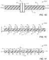
- FIGS. 1C and 1D illustrate schematically embodiments 300 and 400, where fuel and oxidant conduits are separated in embodiment 300 by a large distance d 1 , for example several feet, or alternatively wherein fuel and oxidant conduits are adjacent in embodiment 400; in certain embodiments fuel and oxidant conduits may be attached or formed together.
- Embodiment 300 and 400 also illustrate two possible edge-joining shapes, with embodiment 300 of FIG. 1C illustrating edge 12 having a male portion 20 configured to fit into a female-shaped portion 22 of edge 14 of another panel body.
- Embodiment 400 of Fig. 1D illustrates saw tooth patterns 24, 26, on edges 12, 14, respectively.
- FIG. 1E illustrates schematically embodiment 500, wherein the volume of fuel and/or oxidant flowing through one or more fuel and/or oxidant conduits could be decreased, necessitating more insertion points though paired fuel and oxidant conduits.
- FIG. 1F illustrates schematically embodiment 600, wherein fuel and oxidant conduits are equally spaced through out the burner body panel, and thus throughout the SCM if these panels were installed in an SCM floor. Edges 12 and 14 are illustrated as squared edges, and major surfaces 8 and 10 are illustrated as substantially flat in embodiment 600.
- Burner body panel (panel body) 2 may have a thickness "t", as indicated in FIG. 1E , in the range of at least 0.5 cm or greater; for example, the body panel may have a thickness in the range of at least 1 cm or greater; or in the alternative, the body panel may have a thickness in the range of at least 5 cm or greater; or in the alternative, the body panel may have a thickness in the range of at least 15 cm or greater; or in the alternative, the body panel may have a thickness in the range of at least 25 cm or greater; or in the alternative, the body panel may have a thickness in the range of at least 30 cm or greater.
- the body panel may comprise a single layer; or in the alternative, the body panel may comprise two or more layers or sub-panels.
- FIGS. 2A-2E illustrate schematically, in plan view, a number of SCM burner panel embodiments in accordance with the present disclosure.
- Embodiment 700 illustrated schematically in FIG. 2A is an embodiment wherein the ratio of oxidant and fuel insertion conduits may vary from 1:1; in embodiment 700 the ratio of O:F conduits is 4:1. All individual values and subranges from about 1:10 to about 10:1 are included herein and disclosed herein.
- the ratio of oxidant to fuel conduits may range from a lower limit of about 1:10, 2:10, 3:10, 5:10, 7:10, to 9:10 or 1:1 to an upper limit of 10:5, 10:4, 10:3, 10:2, or about 10:1.
- the ratio of oxidant to fuel conduits may be in the range of from about 2:10 to about 10:5, or in the alternative, the ratio of oxidant to fuel conduits may be in the range of from about 3:10 to about 10:4, or in the alternative, the ratio of oxidant to fuel conduits may be in the range of from about 1:1 to about 10:5.
- FIG. 2A also illustrates edges 16, 18, as well as distance d 4 , illustrating the distance of oxidant conduit 6 from edge 16.
- Distance d 4 may range from about the range of at least 5 cm or greater; for example, the distance d 4 may have a magnitude in the range of at least 10 cm or greater; or in the alternative, the distance d 4 may have a magnitude in the range of at least 12 cm or greater; or in the alternative, the distance d 4 may have a magnitude in the range of at least 15 cm or greater; or in the alternative, the distance d 4 may have a magnitude in the range of at least 20 cm or greater.
- the magnitude of distance d 4 is limited only by the width of the body panel W (as illustrated in FIG. 2B ).
- FIGS. 2B illustrates schematically another burner panel embodiment 1100, wherein a series of burner panels 2, each of length I 1 , may be pieced together to form a portion of or the entire SCM floor having a length 12, and the pattern of fuel and oxidant conduits 4, 6 extended or changed from one panel 2 to the next. Indeed, the lengths of panels 2 may or may not be the same length I 1 or width W.
- the fuel and oxidant conduits 4, 6 are rectangular, with alternating fuel and oxidant conduits along the length of the panel body 2.
- FIGS. 2C, 2D, and 2E illustrate schematically three other burner panel embodiments 1200, 1300, and 1400, of the present disclosure.
- Fuel and oxidant slots 4, 6 may be linear or nonlinear, co-aligned or purposely misaligned, or in an alternating pattern, each combination optimized for component life and for energy effectiveness.
- Each embodiment illustrated in FIGS. 2A-2E may be assembled in a repeating pattern as illustrated schematically in FIG. 2B , the separate burner panels 2 being joined at seams 90.
- Embodiment 1200 illustrates schematically an embodiment having semi-circular slot fuel and oxidant conduit cross-sections
- embodiment 1300 illustrates schematically an embodiment having semi-circular fuel and oxidant conduit cross-sections
- embodiment 1400 illustrates schematically an embodiment having rectangular fuel and oxidant conduit cross-sections, where each fuel conduit 4 is larger than its corresponding oxidant conduit 6, and all fuel conduits 4 are in a line, and all oxidant conduits 6 are in a line parallel to the fuel conduits.
- FIG. 3 illustrates schematically, embodiment 800, wherein fuel and oxidant are injected at the same point but may be injected at different times through a single (delivery) conduit 36 connected fluidly at 38 to a "T" connection 40, and to an oxidant supply conduit 42 and associated valve or flow oscillator 46, and to a fuel supply conduit 44 and associated valve or flow oscillator 48.
- a single (delivery) conduit 36 connected fluidly at 38 to a "T" connection 40, and to an oxidant supply conduit 42 and associated valve or flow oscillator 46, and to a fuel supply conduit 44 and associated valve or flow oscillator 48.
- a burner flowing only oxygen for 1 second and then only fuel for 1 second thus, the oxygen and fuel would mix above the burner tip keeping most combustion away from the burner tip.
- FIGS. 4A and 4B illustrate schematic plan views of burner panel embodiments 900 and 1000, where slot nozzles may be employed for fuel or oxidant, with the other of the two materials injected through a plurality of smaller nozzles, in embodiment 900 small round nozzles.
- Burner panel embodiment 900 includes a frame 50 including first and second main frame pieces 52, 54 and third and fourth end frame pieces 56, 58 enclosing three slot nozzles 60, 62, 64, each of height h3 and each defining an internal space 66 for flow of fuel or oxidant.
- a wall 70 may separate slot nozzles 60 and 62, and a wall 72 may separate slot nozzles 62 and 64. In other embodiments, walls 70, 72 may not be necessary.
- Small circular nozzles 68 of diameter d5 are positioned within the slot nozzles 60, 62, 66 as illustrated, it being understood that more or less small nozzles 68 may be positioned in the respective slot nozzles, and the number of small nozzles 68 may not be the same in each slot nozzle.
- Height h3 may range from about the range of at least 5 cm or greater; for example, the height h3 may have a magnitude in the range of at least 10 cm or greater; or in the alternative, the height h3 may have a magnitude in the range of at least 12 cm or greater; or in the alternative, the height h3 may have a magnitude in the range of at least 15 cm or greater; or in the alternative, the height h3 may have a magnitude in the range of at least 20 cm or greater.
- the magnitude of height h3 is limited only by the width of the body panel W and the number of slot nozzles.
- the upper limit of the magnitude of d5 is limited by the value of h3, but may generally range from about 2 to about 10 cm.
- a plurality of slot nozzles 76, 78, 82, 84, and 86 may be employed for fuel or oxidant, with the other of the two combustion materials injected through surrounding internal spaces 74, 80, and 81 defined by frame pieces 52, 54, 56, and 58, as well as walls 70, 72.
- the magnitude of width "w" of slot nozzles 76, 78, 82, 84, and 86 is limited by the distance between frame pieces and walls, but may generally range from about 2 to about 10 cm.
- Another option to approach separation of the fuel and oxidant is to generate separate permeable, or diffused zones in the melter that emit fuel and oxidant separately.
- This concept can include arrays of small holes, permeable membranes, porous materials and so forth. These systems may take on many forms. In one such embodiment, discrete zones or panels where each supplies only oxidant or fuel.
- Another embodiment may be a single panel with primarily oxidant on one side and primarily fuel on the other side with a gradual transition from one end to the other and fuel to oxidant with the center portion of the panel having a mixture of both.
- This embodiment may also include discrete and variably shaped zones within a given panel where oxidant and fuel may be added separately involving patterns such as checkerboards, waves, and countless others.
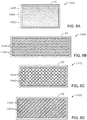
- FIGS. 5A-5D illustrate schematically, in plan view, four other SCM burner panel embodiments in accordance with the present disclosure, each including independent zones of permeable material or arrays of small diameter holes that enable fuel and oxidant to enter the SCM. These embodiments are only examples of a plethora of patterns enabling the interaction of the fuel and oxidant.
- the burner panel may either be independent panels within a melter floor or serve as the floor itself.
- 5A includes a frame 50 enclosing a porous material allowing three overlapping zones 1422 for fuel or oxidant, zone 1424 where fuel and oxidant are both injected, and zone 1426 where predominantly oxidant or fuel may be injected from the bottom and/or side of an SCM for submerged combustion.
- Embodiment 1430 illustrated schematically in plan view in FIG. 5B includes a frame 50 enclosing alternating chevron patterned regions 1432 and 1434 for fuel and/or oxidant injection, the patterned regions formed by the same or different porous material in each region.
- One set of chevron patterned region 1432 or 1434 would allow passage of oxidant, while the other set would allow for passage of fuel.
- Embodiment 1440 illustrated schematically, in plan view in FIG. 5C includes a frame 50 enclosing alternating square or diamond patterned regions 1442 and 1444 for fuel and/or oxidant injection, the patterned regions formed by the same or different porous material in each region.
- One set of square or diamond patterned regions 1442 or 1444 would allow passage of oxidant, while the other set would allow for passage of fuel.
- Embodiment 1450 illustrated schematically, in plan view in FIG. 5D includes a frame 50 enclosing alternating line patterned regions 1452 and 1454 for fuel and/or oxidant injection, the patterned regions formed by the same or different porous material in each region.
- One set of line patterned region 1452 or 1454 would allow passage of oxidant, while the other set would allow for passage of fuel.
- SCM embodiment 450 comprises a melter having a floor 2 (which may be a burner panel in accordance with the present disclosure), a roof or ceiling 452, a feed end wall 454A, a first portion of an exit end wall 454B, and a second portion of the exit end wall 454C.
- Feed end wall 454A and exit end wall portion 454B may form angles " ⁇ " and " ⁇ ", respectively, with respect to floor 2, as indicated.
- Angles ⁇ and ⁇ may be the same or different, and generally may range from about 30 degrees to about 90 degrees, or from about 45 degrees to about 75 degrees.
- Exit end wall portion 454C may form an angle " ⁇ " with respect to skimmer 480.
- Angle ⁇ may be the range from 0 to about 70 degrees, or from about 30 degrees to about 75 degrees. Increasing this angle beyond these ranges may require more floor space for the melters, and/or more material of construction, both of which are generally undesirable. Decreasing this angle may promote escape of unmelted or melted material up stack 456, or deposition onto internal surfaces of stack 456, both of which are also undesirable.
- a frozen and/or highly viscous glass layer or layers 470 may be formed on the inside surfaces of walls 454A, 454B, due to the use of fluid-cooled panels for these walls.
- walls 454A, 454B, 454C, floor 2, and roof 452 may be comprised of a metal shell 472 and a fluid-cooled refractory panel 474.
- System embodiment 450 further includes an exhaust stack 456, and submerged combustion fuel and oxidant conduits 4, 6, in burner panel 2 which create during operation a highly turbulent melt indicated at 468.
- fuel and oxidant conduits 4, 6 are positioned to emit fuel and oxidant into molten glass in the melting zone 464 in a fashion so that the gases combust and penetrate the melt generally perpendicularly to floor panel 2.
- one or more fuel or oxidant conduits 4, 6 may emit fuel or oxidant into the melt at an angle to floor 2, where the angle may be more or less than 45 degrees, but in certain embodiments may be 30 degrees, or 40 degrees, or 50 degrees, or 60 degrees, or 70 degrees, or 80 degrees.
- the initial raw material can be introduced into the melter of system 450 on a batch, semi-continuous or continuous basis.
- a port 460 is arranged at end 454A of the melter through which the initial raw material is introduced by a feeder 458.
- a "batch blanket" 462 may form along wall 454A, as illustrated.
- Feed port 460 may be positioned above the average glass melt level, indicated by dashed line 466.
- the amount of the initial raw material introduced into the melter is generally a function of, for example, the capacity and operating conditions of the melter as well as the rate at which the molten material is removed from the melter.
- the initial raw material feedstock may include any material suitable for forming molten inorganic materials, such as glass, such as, for example, limestone, glass, sand, soda ash, feldspar and mixtures thereof.
- a glass composition for producing glass fibers is "E-glass," which typically includes 52-56% SiO 2 , 12-16% Al 2 O 3 , 0-0.8% Fe 2 O 3 , 16-25% CaO, 0-6% MgO, 0-10% B 2 O 3 , 0-2% Na 2 0+K 2 O, 0-1.5% TiO 2 and 0-1% F 2 .
- Other glass compositions may be used, such as those described in assignee's published U.S. application 20080276652 .
- the initial raw material can be provided in any form such as, for example, relatively small particles, or in the case of rock wool or mineral wool manufacture, in large pieces 5 cm or more in diameter.
- submerged combustion burners and burner panels may produce violent turbulence of the molten inorganic material in the SCM and may result in sloshing of molten material, pulsing of combustion burners, popping of large bubbles above submerged burners, ejection of molten material from the melt against the walls and ceiling of melter, and the like.
- one or more of these phenomena may result in undesirably short life of temperature sensors and other components used to monitor a submerged combustion melter's operation, making monitoring difficult, and use of signals from these sensors for melter control all but impossible for more than a limited time period.
- Processes and systems of the present disclosure may include indirect measurement of melt temperature in the melter itself, as disclosed in assignee's U.S.
- thermocouples for monitoring and/or control of the melter, for example using a controller.
- a signal may be transmitted by wire or wirelessly from a thermocouple to a controller, which may control the melter by adjusting any number of parameters, for example feed rate of feeder 458 may be adjusted through a signal, and one or more of fuel and/or oxidant conduits 4,6 may be adjusted via a signal, it being understood that suitable transmitters and actuators, such as valves and the like, are not illustrated for clarity.
- system embodiment 450 includes a melter exit structure 476 for discharging the molten glass or similar material.
- Melter exit structure 476 is positioned generally downstream of melter exit ends 454B, 454C as illustrated of FIG. 6 , and may fluidly and mechanically connect the melter vessel to a molten glass conditioning channel (not illustrated).
- Melter exit structure 476 comprises a fluid-cooled transition channel 478, having generally rectangular cross-section in embodiment 450, although any other cross-section would suffice, such as hexagonal, trapezoidal, oval, circular, and the like.
- fluid-cooled transition channel 478 is configured to form a frozen glass layer or highly viscous glass layer, or combination thereof, on inner surfaces of fluid-cooled transition channel 478 and thus protect melter exit structure 476 from the mechanical energy imparted from the melter vessel to melter exit structure 476.
- Melter exit structure 476 may in certain embodiments comprise an essentially rectangular, fluid-cooled, ceramic or metallic box having a length, a width, a height. In these embodiments, length may range from about 5 to about 50 percent, or from about 10 to about 40 percent, of the entire length of the melter apparatus.
- the width of melt exit structure 476 may be the same as the width of the melter apparatus, or may be less or more than the width of the melter apparatus.
- the height may range from about 5 to about 50 percent, or from about 10 to about 40 percent, of the entire height of the melter apparatus, measured from floor 2 to ceiling 4.
- Melter length, width and height depend primarily on the amount of raw material to be fed, the amount of molten glass to be produced, and the desired throughputs mentioned herein.
- a fluid-cooled skimmer 480 may be provided, extending downward from the ceiling of the melter vessel and positioned upstream of fluid-cooled transition channel 478. Fluid-cooled skimmer 480 has a lower distal end 482 extending a distance L s ranging from about 1 inch to about 12 inches (from about 2.5 cm to about 30 cm) below the average melt level 466. Fluid-cooled skimmer 480 may be configured to form a frozen glass layer or highly viscous glass layer, or combination thereof, on its outer surfaces. Skimmer lower distal end 482 defines, in conjunction with a lower wall of melter exit structure 476, a throat 484 of the melter vessel, throat 484 configured to control flow of molten glass from the melter vessel into melter exit structure 476.
- the throat 484 is arranged below average melt level 466.
- Molten material can be removed from melter exit structure 476 on a batch, semi-continuous basis or continuous basis.
- the molten material continuously flows through throat 484 and generally horizontally through melter exit structure 476, and is removed continuously from melter exit structure 476 to a conditioning channel (not illustrated). Thereafter, the molten material can be processed by any suitable known technique, for example, a process for forming glass fibers.
- Certain embodiments may include an overlapping refractory material layer 486 on at least the inner surface of fluid-cooled transition channel 478 that are exposed to molten material.
- the overlapping refractory material may comprise a seamless insert of dense chrome, molybdenum, or other dense ceramic or metallic material.
- the dense chrome or other refractory material may be inserted into the melter exit structure and may provide a seamless transition form the melter vessel to a conditioning channel (not illustrated).
- Dam opening 488 accommodates a movable, fluid-cooled dam 490, which is illustrated schematically in FIG. 6 in a retracted position. Dam 490 may be manipulated by a prime mover 492, such as one or more motors, jack screws, or the like. Fluid-cooled dam 490 comprises dimensions allowing the dam to be extended an entire distance from top to bottom of fluid-cooled transition channel 478 and completely isolate the melting zone of the melter vessel from the conditioning channel.
- Melter apparatus in accordance with the present disclosure may also comprise one or more wall-mounted submerged combustion burners, and/or one or more roof-mounted burners (not illustrated). Roof-mounted burners may be useful to pre-heat the melter apparatus melting zones, and serve as ignition sources for one or more submerged combustion burners and/or burner panels. Melter apparatus having only wall-mounted, submerged-combustion burners or burner panels are also considered within the present disclosure. Roof-mounted burners may be oxy-fuel burners, but as they are only used in certain situations, are more likely to be air/fuel burners. Most often they would be shut-off after pre-heating the melter and/or after starting one or more submerged combustion burners.
- all submerged combustion burners and burner panels are oxy/fuel burners or oxy-fuel burner panels (where "oxy" means oxygen, or oxygen-enriched air, as described earlier), but this is not necessarily so in all embodiments; some or all of the submerged combustion burners or burner panels may be air/fuel burners.
- heating may be supplemented by electrical heating in certain embodiments, in certain melter zones.
- Suitable materials for glass-contact refractory which may be present in SC melters and downstream flow channels, and refractory panel bodies of burner panels, include fused zirconia (ZrO 2 ), fused cast AZS (alumina-zirconia-silica), rebonded AZS, or fused cast alumina (Al 2 O 3 ).
- the melter geometry and operating temperature, burner body panel geometry, and type of glass or other product to be produced, may dictate the choice of a particular material, among other parameters.
- fluid-cooled means use of a coolant fluid (heat transfer fluid) to transfer heat away from the burner panel or other component (such as structural walls of an SCM), either by the fluid traveling through the refractory of the panel, through conduits positioned in or adjacent the refractory of the panel, and the like, and does not include natural heat transfer that may occur by ambient air flowing past the panel, or ambient air merely existing adjacent a panel.
- Heat transfer fluids may be any gaseous, liquid, slurry, or some combination of gaseous, liquid, and slurry compositions that functions or is capable of being modified to function as a heat transfer fluid.
- Gaseous heat transfer fluids may be selected from air, including ambient air and treated air (for example, air treated to remove moisture), inorganic gases, such as nitrogen, argon, and helium, organic gases such as fluoro-, chloro- and chlorofluorocarbons, including perfluorinated versions, such as tetrafluoromethane, and hexafluoroethane, and tetrafluoroethylene, and the like, and mixtures of inert gases with small portions of non-inert gases, such as hydrogen.
- Heat transfer liquids and slurries may be selected from liquids and slurries that may be organic, inorganic, or some combination thereof, for example, salt solutions, glycol solutions, oils and the like. Other possible heat transfer fluids include steam (if cooler than the expected glass melt temperature), carbon dioxide, or mixtures thereof with nitrogen. Heat transfer fluids may be compositions comprising both gas and liquid phases, such as the higher chlorofluorocarbons.
- Certain SCMs of this disclosure may comprise one or more non-submerged burners.
- Suitable non-submerged combustion burners may comprise a fuel inlet conduit having an exit nozzle, the conduit and nozzle inserted into a cavity of a ceramic burner block, the ceramic burner block in turn inserted into either the SCM roof or the SCM wall structure, or both the SCM roof and SCM wall structure.
- Downstream flow channels may also comprise one or more non-submerged burners.
- one or more fuel and/or oxidant conduits in the SCM and/or flow channel(s) downstream thereof may be adjustable with respect to direction of flow of the fuel or oxidant or both. Adjustment may be via automatic, semi-automatic, or manual control.
- Certain system embodiments may comprise a mount that mounts the fuel or oxidant conduit in a burner panel of the SCM and/or flow channel comprising a refractory, or refractory-lined ball joint.
- Other mounts may comprise rails mounted in slots in the wall or roof.
- the fuel and/or oxidant conduits may be mounted outside of the melter or channel, on supports that allow adjustment of the fuel or oxidant flow direction. Useable supports include those comprising ball joints, cradles, rails, and the like.
- Certain SCMs and method embodiments of this disclosure may include fluid-cooled panels such as disclosed in assignee's U.S. Patent No. 8,769,992 .
- Certain systems and processes of the present disclosure may utilize measurement and control schemes such as described in assignee's U.S. Patent No. 9,086,453 , and/or feed batch densification systems and methods as described in assignee's co-pending U.S. Patent Application Serial No. 13/540,704, filed July 3, 2012 .
- Certain SCMs and processes of the present disclosure may utilize devices for delivery of treating compositions such as disclosed in assignee's U.S. Patent No. 8,973,405 .
- Certain SCMs and process embodiments of this disclosure may be controlled by one or more controllers.
- combustion (flame) temperature may be controlled by monitoring one or more parameters selected from velocity of the fuel, velocity of the primary oxidant, mass and/or volume flow rate of the fuel, mass and/or volume flow rate of the primary oxidant, energy content of the fuel, temperature of the fuel as it enters the burner panel, temperature of the primary oxidant as it enters the burner panel, temperature of the effluent, pressure of the primary oxidant entering the burner panel, humidity of the oxidant, burner panel geometry, combustion ratio, and combinations thereof.
- Certain SCMs and processes of this disclosure may also measure and/or monitor feed rate of batch or other feedstock materials, such as glass batch, cullet, mat or wound roving and treatment compositions, mass of feed, and use these measurements for control purposes.
- the burner panels of the present disclosure include a burner body 3 and three internal chambers inside of the burner panel or melter floor panel, each chamber immediately below the next in elevation, with multiple ports from each of the fuel and oxidant chambers being fitted to eject the fuel and oxidant into the melter interior, and the "topmost"chamber being actively fluid-cooled to both ensure safety and long term survivability of the burner.
- the general configuration of the three chambers is as illustrated schematically in the simplified vertical cross-sectional view of FIG. 8 , embodiment 1500, with the oxidant supply, fuel supply, cooling supply, and cooling return conduits not shown, and with only one fuel and one oxidant port (of many) illustrated for simplicity.
- a top panel 102 includes through passages 104, 106 for fuel and oxidant conduits 4, 6, while a second panel or tube table 110 includes corresponding through passages 116 for fuel and through passage 118 for oxidant, and a third panel 112 includes through passages 120 only for oxidant.
- a sidewall structure 108 and fourth panel 114 complete this simplified structure. Three internal chambers are thus formed, 122 (coolant chamber) for coolant fluid, 124 (fuel chamber) for fuel, and 126 (oxidant chamber) for oxidant.
- the fuel and oxidant chambers 124, 126 may be alternatively swapped in position to each otherfrom that illustrated in the schematic cross-section of FIG. 8 (i.e., oxidant chamber may be above fuel chamber).
- Embodiments to provide oxidant supply, fuel supply, cooling supply, and cooling return into and through the various chambers may vary in geometry such that various arrangements of alternating oxidant and fuel ports may be created.
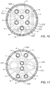
- Two example configurations are illustrated in schematic plan views, partially in phantom, in FIGS. 10 and 11 , with certain cross-sectional simplicities made and liberties taken, for ease of illustration. While FIGS. 10 and 11 illustrate a circular burner (or circular burner area in the melter floor panel) in plan view, the burner may comprise other shapes such as square, rectangular, polygonal, or other, without constraint, so long as the cooling, fuel, and oxidant chambers are formed and various conduits are added to eject the fuel and oxidant. While the schematic illustrations of FIGS.
- conduits 10 and 11 illustrate two preferred arrangements of alternating oxidant conduits 6 and fuel conduits 4 to maximize comingling of the gases and to maximize energy release
- the conduits may be arranged in any number of patterns, alternating in rows, or in areas, in columns, or in any number of other patterns to effect flame behavior differences and/or glass circulation differences within the affected volume above each burner and between adjacent burners. While FIGS. 10 and 11 illustrate conduits having circular openings, the conduits may be any number of shapes such as slots, circles, squares, rectangles, or other polygonal shapes.
- the fluid flow behaviors within each chamber and through the various oxidant and fuel conduits may be altered through a combination of conduit placement, supply placement, chamber height, and placement of any flow diverters, diffusing baffles or screens, or other components within the areas of flow such that all conduits carry purposeful amounts of the total flow, both equal or unequal.
- Such flow diverters thereby allow the flows out the top surface of the burner to be tailored.
- diverters may be sized and positioned to ensure all conduits are flowing equally, or may be sized and positioned to give preference to fuel flow more centrally in plan view and oxidant flow more peripherally in plan view, or profiled from lowest to highest flows out the top surface of the burner laterally.
- Such tailoring enabled by the design of the burner incorporating chambers, and judiciously positioning such burners within the overall melter floor plan, allows the SCM to have flames that encourage glass flow in specific patterns within the melter, those molten product flow patterns having operational benefit to the glass or other material produced, the melter walls or structure, energy utilization, or other performance attributes.
- FIGS. 9A and 9B are schematic exploded perspective views, of two burner embodiments 550 and 580 of the present disclosure.
- the burner designs were conceived to produce subassemblies of the burner as a single specially-formed component, rather than as a subassembly made from a high quantity of common shapes which have to be welded together.
- the result is a more homogeneous metallic microstructure, with less welding, brazing, or fusing, and therefore with fewer opportunities for leakage between adjacent chambers inside the burner from fabrication welding issues and fewer opportunities for the part to fail while in service.
- both burners 550 and 580 have the exact same function once assembled.
- the burner of embodiment 550 is designed and fabricated using a high quantity of parts, each having to be welded or fused together. These parts include six fuel conduits 4; six oxidant conduits 6; two coolant supply conduits 501; two coolant return conduits 503; a burner top or (planar) cap 502 having through holes, exits or ports 504, 506 for the six fuel and the six oxidant fuel conduits; a burner wall structure 508; plates 510, 512, and 514; ceramic side panels 517, 518, and 519, and a ceramic fitting 516.
- burner embodiment 580 is fabricated from a small number of specially formed parts: parts 520 (a combination of parts 502 and 508); a tube table part 522 (a combination of parts 4, 6, 510, 514, 516, 517, and 519); part 524 (a combination of parts 512, 516, and 518); and part 526 (a combination of part 514 and a downward vertical piece).
- Burner embodiment 550 of FIG. 9A has 21 parts above the dashed line "A"; burner embodiment 580 of FIG. 9B has 4 parts and requires approximately 17fewer welds.
- the 4 parts of burner embodiment 580 are more complex to form.
- the 4 complex parts illustrated in burner embodiment 580 may be formed by one or more methods selected from CNC machining each shape from a billet, EDM cutting each shape from a billet, direct laser metal sintering (such as rapid prototyping, metal 3D printing, SLA printing), near-net or net-shape casting, and other technologies which produce such specially formed shapes from uniform materials.
- a heat treatment process may be applied to improve the microstructural attributes and stored stresses of the specially formed shapes, and/or of the completed assembly.
- the heat treatments are material specific, and include classical time-temperature heat treatments, or time-pressure-temperature treatments (for example, hot isostatic pressing).
- the treatments enable the desired microstructure in the material within the specially formed shapes, the seams and seam heat-affected zones, and in the full assembly. While there is a specific design illustrated in FIG. 9B and in the above discussion, the design and fabrication approach is not constrained to that shown. The method described is applicable to other internal geometries and configurations for burner components where there are large, frequent temperature changes imposedon the assembly while it is in service.
- the pint of this disclosure is to disclose a range of fabricating technologies and internal design features which may enable producing burner assemblies and burner panels having the fewest number of parts, the fewest number of seams possible, thereby ensuring more robust components in service and reduced potential for failure of the assemblies.
- a method of fabricating such a burner and burner panel is an aspect of the present disclosure.
- One method embodiment 750 is illustrated in the logic diagram of FIG. 7 .
- the method comprises (a) forming components, in no particular order (box 752):
- a "primary" oxidant supply conduit 566 routes oxidant to oxidant conduits 6, and a “primary” fuel supply conduit 568 routes fuel to fuel conduits 4.
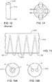
- FIG. 12 is a schematic perspective view of a prior art metal ingot
- FIGS. 13, 14, 15A, and 15B are schematic side elevation, bottom plan, and plan views of portions of a burner made from a metal ingot such as illustrated schematically in FIG. 12 .
- submerged combustion burners endure a harsh environment, must be actively cooled, and also must be configured to supply both oxidant and fuel through the burner.
- the internal features of the burner can be quite complex and portions of the burner often have to be precision machined and made from materials that are weldable, therefore material selection is limited and complexity of the burner is high.
- One solution to this dilemma simplifies the burner configuration by making the burner from a single "slug", “ingot”, or other form of material that has no seams or joints. The material simply needs to be drillable and “water” tight, and enables using materials that would otherwise not be practical with burners fabricated from multiple components. Examples of such materials are molybdenum, carbon, and certain ceramics.
- the improved burner design begins as a circular cylinder of appropriate diameter and length, as illustrated schematically in FIG. 12 at 602.
- Cooling passages 608, typically water-cooling, are drilled in such a manner that subsequent holes intercept each other near the "tip" 604 without penetrating the tip.
- the holes then are interconnected at the base 606 of the burner, allowing the cooling fluid to be recirculated from the base 606 to near the tip 604 and back to the base 606 in a series of passages.
- the passages 608 may be configured as illustrated in FIG. 13 .
- the drilled passages 608 are threaded and fittings (not illustrated) may be installed such that the cooling passages 608 are interconnected and have a single coolant supply "CS" and coolant return “CR” as illustrated in FIG. 14 .
- each cooling passage may be connected to a supply and return, i.e., in parallel.
- the fuel and oxidant supply passages are through-drilled from base to tip and can be of multiple configurations.
- a couple possible ways to deliver fuel and oxidant separately through the burner are a larger passage with an inner concentric tube made from a separate component and fitted into place, or side-by-side passages, as illustrated schematically in FIGS. 15A and 15B . In either case, the base of the burner would have appropriate fittings and connections to supply the fuel and oxidant. These examples are not all inclusive, but are generally illustrative of preferred embodiments.
- Oxidant and fuel conduits of burner panels of the present disclosure may be comprised of metal, ceramic, ceramic-lined metal, or combination thereof.
- Suitable metals include carbon steels, stainless steels, for example, but not limited to, 306 and 316 steel, as well as titanium alloys, aluminum alloys, and the like.
- High-strength materials like C-110 and C-125 metallurgies that are NACE qualified may be employed for burner body components. (As used herein, "NACE” refers to the corrosion prevention organization formerly known as the National Association of Corrosion Engineers, now operating under the name NACE International, Houston, Texas.)
- Use of high strength steel and other high strength materials may significantly reduce the conduit wall thickness required, reducing weight of the burners and/or space required for burners.
- Oxidant and fuel conduits of burner panels of the present disclosure, or tips thereof may comprise noble metals and/or other exotic corrosion and/or fatigue-resistant materials, such as platinum (Pt), ruthenium (Ru), rhodium (Rh), palladium (Pd), silver (Ag), osmium (Os), iridium (Ir), and gold (Au); alloys of two or more noble metals; and alloys of one or more noble metals with a base metal.
- the conduit tip may comprise an 80 wt. percent platinum/20 wt.
- burner panels will have a satisfactory service life of at least 12 months under conditions existing in a continuously operating SCM.
- the SCM may comprise a floor, a roof, and a sidewall structure connecting the floor and roof defining an internal space, at least a portion of the internal space comprising a melting zone, and one or more combustion burner panels of this disclosure in either the floor, the roof, the sidewall structure, or any two or more of these, producing combustion gases and configured to emit the combustion gases from a position under a level of, and positioned to transfer heat to and produce, a turbulent molten mass of glass containing bubbles in the melting zone.
- the total quantities of fuel and oxidant used by burner panels of the present disclosure may be such that the flow of oxygen may range from about 0.9 to about 1.2 of the theoretical stoichiometric flow of oxygen necessary to obtain the complete combustion of the fuel flow. Another expression of this statement is that the combustion ratio may range from about 0.9 to about 1.2.
- the velocity of the fuel in the various burner panel embodiments of the present disclosure depends on the burner panel geometry used, but generally is at least about 15 meters/second (m/s).
- the upper limit of fuel velocity depends primarily on the desired penetration of flame and/or combustion products into the glass melt and the geometry of the burner panel; if the fuel velocity is too low, the flame temperature may be too low, providing inadequate temperature in the melter, which is not desired, and if the fuel flow is too high, flame and/or combustion products might impinge on a melter wall or roof, or cause carryover of melt into the exhaust, or be wasted, which is also not desired.
- Oxidant velocity should be monitored so that flame and/or combustion products do not impinge on an SCM wall or roof, or cause carryover of melt into the exhaust, or be wasted. Oxidant velocities depend on fuel flow rate and fuel velocity, but in general should not exceed about 200 ft/sec at 400 scfh flow rate.
- a combustion process control scheme may be employed.
- a master controller may be employed, but the disclosure is not so limited, as any combination of controllers could be used.
- the controller may be selected from PI controllers, PID controllers (including any known or reasonably foreseeable variations of these), and may compute a residual equal to a difference between a measured value and a set point to produce an output to one or more control elements.
- the controller may compute the residual continuously or non-continuously.
- Other possible implementations of the disclosure are those wherein the controller comprises more specialized control strategies, such as strategies selected from feed forward, cascade control, internal feedback loops, model predictive control, neural networks, and Kalman filtering techniques.
- control means to verify or regulate by comparing with a standard or desired value.
- Control may be closed loop, feedback, feed-forward, cascade, model predictive, adaptive, heuristic and combinations thereof.
- controller means a device at least capable of accepting input from sensors and meters in real time or near-real time, and sending commands directly to burner panel control elements, and/or to local devices associated with burner panel control elements able to accept commands.
- a controller may also be capable of accepting input from human operators; accessing databases, such as relational databases; sending data to and accessing data in databases, data warehouses or data marts; and sending information to and accepting input from a display device readable by a human.
- a controller may also interface with or have integrated therewith one or more software application modules, and may supervise interaction between databases and one or more software application modules.
- PID controller means a controller using proportional, integral, and derivative features. In some cases the derivative mode may not be used or its influence reduced significantly so that the controller may be deemed a PI controller. It will also be recognized by those of skill in the control art that there are existing variations of PI and PID controllers, depending on how the discretization is performed. These known and foreseeable variations of PI, PID and other controllers are considered within the disclosure.
- the controller may utilize Model Predictive Control (MPC).
- MPC is an advanced multivariable control method for use in multiple input/multiple output (MIMO) systems.
- MPC computes a sequence of manipulated variable adjustments in order to optimise the future behavior of the process in question. It may be difficult to explicitly state stability of an MPC control scheme, and in certain embodiments of the present disclosure it may be necessary to use nonlinear MPC.
- PID control may be used on strong mono-variable loops with few or nonproblematic interactions, while one or more networks of MPC might be used, or other multivariable control structures, for strong interconnected loops.
- computing time considerations may be a limiting factor.
- Some embodiments may employ nonlinear MPC.
- a feed forward algorithm if used, will in the most general sense be task specific, meaning that it will be specially designed to the task it is designed to solve. This specific design might be difficult to design, but a lot is gained by using a more general algorithm, such as a first or second order filter with a given gain and time constants.
Landscapes
- Engineering & Computer Science (AREA)
- Chemical & Material Sciences (AREA)
- Combustion & Propulsion (AREA)
- Mechanical Engineering (AREA)
- General Engineering & Computer Science (AREA)
- Materials Engineering (AREA)
- Organic Chemistry (AREA)
- Gas Burners (AREA)
- Glass Melting And Manufacturing (AREA)
- Glass Compositions (AREA)
Claims (15)
- Untergetauchte Verbrennungsbrennerplatte (100, 200, 300, 400, 500, 600, 700, 1100, 1200, 1300, 1400), umfassend:(a) einen Plattenkörper (2) mit ersten (8) und zweiten (10) Hauptoberflächen;(b) mindestens einen Oxidationsmitteldurchgang in dem Plattenkörper (2), der sich von der ersten (8) bis zur zweiten (10) Hauptoberfläche erstreckt;(c) mindestens einen Kraftstoffdurchgang im Plattenkörper (2), der sich von der ersten (8) bis zur zweiten (10) Hauptoberfläche erstreckt;(d) mindestens eine Oxidationsmittelzufuhrleitung (6), die in dem mindestens einen Oxidationsmitteldurchgang angeordnet ist;(e) mindestens eine Kraftstoffzufuhrleitung (4), die in dem mindestens einen Kraftstoffdurchgang angeordnet ist;wobei jede der Oxidationsmittelzufuhrleitungen (6) und Kraftstoffzufuhrleitungen (4) proximale (34, 30) und distale (32, 28) Enden umfasst, wobei mindestens einige der distalen Enden (32, 28) von der ersten Hauptfläche (8) des Plattenkörpers (2) entfernt angeordnet sind.
- Brennerplatte (100, 200, 300, 400, 500, 600, 700, 1100, 1200, 1300, 1400) nach Anspruch 1, wobei der mindestens eine Oxidationsmitteldurchgang eine Vielzahl von Oxidationsmitteldurchgängen umfasst, wobei die mindestens eine Oxidationsmitteldurchgangsleitung (6) eine Vielzahl von Oxidationsmitteldurchgangsleitungen umfasst, die mindestens eine Brennstoffdurchgangsleitung eine Vielzahl von Brennstoffdurchgangsleitungen umfasst, die mindestens eine Kraftstoffzufuhrleitung (4) eine Vielzahl von Kraftstoffzufuhrleitungen umfasst, und wobei die Vielzahlen von Oxidationsmitteldurchgängen und Oxidationsmittelzufuhrleitungen (6) mehr als, gleich oder kleiner als die Vielzahl von Kraftstoffdurchgängen und Kraftstoffzufuhrleitungen (4) sein können.
- Brennerplatte (100, 200, 300, 400, 500, 600, 700, 1100, 1200, 1300, 1400) nach den Ansprüchen 1 oder 2, wobei mindestens ein Teil der mindestens einen Brennstoff- und Oxidationsmittelzufuhrleitungen (4, 6) aus einem einzigen Metallbarren gebildet ist, der darin einen oder mehrere Brennstoff- oder Oxidationsmittelkanäle ausgebildet hat und darin einen oder mehrere Kanäle für Kühlmittel ausgebildet hat.
- Brennerplatte (100, 200, 300, 400, 500, 600, 700, 1100, 1200, 1300, 1400) nach einem der vorhergehenden Ansprüche, wobei jede Oxidationsmittelzufuhrleitung (6) senkrecht zu dem Plattenkörper (2) steht.
- Brennerplatte (100, 200, 300, 400, 500, 600, 700, 1100, 1200, 1300, 1400) nach einem der vorhergehenden Ansprüche, wobei jede Brennstoffzufuhrleitung (4) senkrecht zu dem Plattenkörper (2) steht.
- Brennerplatte (100, 200, 300, 400, 500, 600, 700, 900, 1000, 1100, 1200, 1300, 1400) nach einem der vorhergehenden Ansprüche, wobei mindestens eine Oxidationsmittelzufuhrleitung (6) von mindestens zwei Brennstoffzufuhrleitungen (4) geteilt wird.
- Untergetauchter Verbrennungsbrenner und Rahmenkombination (900, 1000), umfassend:(a) einen Rahmen (50);(b) mindestens eine Schlitzdüse (60, 62, 64), die vom Rahmen gehalten wird, wobei jede Schlitzdüse (60, 62, 64) mindestens einen Brennstoffschlitz umfasst, wobei jeder Brennstoffschlitz innerhalb eines einzelnen Oxidationsmittelschlitzes angeordnet ist.
- Brenner und Rahmenkombination (900, 1000) nach Anspruch 7, wobei der Rahmen (50) eine äußere Wand und mindestens eine innere Wand umfasst, wobei die inneren und äußeren Wände mindestens ein Fach für die mindestens eine Schlitzdüse (60, 62, 64) ausbilden.
- Untergetauchte Verbrennungsbrennerplatte (1420, 1430, 1440, 1450), umfassend:(a) eine Wandstruktur, die einen Innenraum mit einer Länge, einer Breite und einer Dicke definiert;(b) den Innenraum, der vollständig mit einem Material gefüllt ist, das eine zufällige oder nicht zufällige Anordnung von Pfaden durch sie hindurch umfasst, wobei mindestens ein erster Abschnitt der Pfade oxidative Pfade sind, und mindestens ein zweiter Abschnitt der Pfade Kraftstoffpfade sind, nämlich ein Rahmen, der eine der Gruppe umschließt:- ein poröses Material, das drei überlappende Zonen ermöglicht, eine Zone (1422) für Brennstoff oder Oxidationsmittel, eine Zone (1424), in der sowohl Brennstoff als auch Oxidationsmittel eingespritzt werden, und eine Zone (1426), in die überwiegend Oxidationsmittel oder Brennstoff eingespritzt werden kann,- alternierende, mit Chevronmuster versehene Bereiche für die Kraftstoff- und/oder Oxidationsmitteleinspritzung, wobei die gemusterten Bereiche durch das gleiche oder verschiedene poröse Material in jedem Bereich gebildet werden, und wobei ein Satz von mit Chevronmuster versehenen Bereichen den Durchgang von Oxidationsmittel ermöglicht, während der andere Satz den Durchgang von Kraftstoff ermöglicht,- abwechselnde quadratisch oder diamanten gemusterte Bereiche für die Kraftstoff- und/oder Oxidationsmitteleinspritzung, wobei die gemusterten Bereiche durch das gleiche oder verschiedene poröse Material in jedem Bereich gebildet werden, und wobei ein Satz von quadratisch oder diamanten gemusterten Bereichen den Durchgang von Oxidationsmittel ermöglicht, während der andere Satz den Durchgang von Brennstoff ermöglicht, und- abwechselnd liniengemusterte Bereiche für die Brennstoff- und/oder Oxidationsmitteleinspritzung, wobei die gemusterten Bereiche durch das gleiche oder unterschiedliche poröse Material in jedem Bereich gebildet werden, wobei ein Satz von liniengemusterten Bereichen den Durchgang von Oxidationsmittel ermöglicht, während der andere Satz den Durchgang von Brennstoff ermöglicht.
- Brennerplatte (1420, 1430, 1440, 1450) nach Anspruch 9, wobei sich mindestens ein Großteil der Pfade von einer ersten bis zu einer zweiten Hauptoberfläche des Materials erstreckt.
- Verbrennungsbrennerplatte (1420, 1430, 1440, 1450) nach einem der Ansprüche 9 oder 10, wobei die Wandstruktur eine Form bildet, die aus der Gruppe ausgewählt ist, die aus rechteckigen, dreieckigen und unregelmäßigen Formen besteht, die ohne Zwischenräume zusammenpassen.
- Untergetauchter Verbrennungsschmelzer (450), der mindestens eine untergetauchte Verbrennungsbrennerplatte (100, 200, 300, 400, 500, 600, 700, 800, 900, 1000, 1100, 1200, 1300, 1400, 1400, 1420, 1430, 1440, 1450) nach einem der vorhergehenden Ansprüche umfasst.
- Verfahren zum Schmelzen von nichtmetallischem anorganischem Ausgangsmaterial unter Verwendung eines untergetauchten Verbrennungsschmelzers (450), wobei das Verfahren umfasst:(a) Einspeisen des Einsatzmaterials in einen untergetauchten Verbrennungsschmelzer, ausgewählt aus der Gruppe bestehend aus den Schmelzern (100, 200, 300, 400, 500, 600, 700, 800, 900, 1000, 1100, 1200, 1300, 1400, 1420, 1430, 1440, 1450) nach Anspruch 12; und(b) Schmelzen des Einsatzmaterials.
- Untergetauchte Verbrennungsbrennerplatte (1500), umfassend:(a) einen Plattenkörper (2);(b) einen oder mehrere Verbrennungsbrenner, die zufällig oder nicht zufällig in der Platte (2) angeordnet sind, wobei jeder Brenner umfasst:(i) einen Brennerkörper, der eine im Wesentlichen planare Kappe und eine äußere Wand und mindestens zwei innere Wände umfasst, wobei die äußere Wand, die planare Kappe und die inneren Wände so angeordnet sind, dass sie eine Brennstoffkammer (124), eine Oxidationsmittelkammer (126) und eine Kühlmittelkammer (122) bilden, wobei die planare Kappe eine Vielzahl von Brennstoff- und Oxidationsmittelausgängen (504, 506) aufweist;(ii) mindestens eine Kraftstoffleitung (4), die die Kraftstoffkammer (124) mit einer ersten großen Außenfläche der planaren Kappe fluidisch verbindet;(iii) mindestens eine Oxidationsmittelleitung, die die Oxidationsmittelkammer (126) mit der ersten großen Außenfläche der planaren Kappe (502) fluidisch verbindet, und(iv) wobei die Kühlmittelkammer (122) näher an der planaren Kappe positioniert ist als sowohl die Brennstoff- als auch die Oxidationsmittelkammer.
- Verfahren (750) zum Herstellen der untergetauchten Verbrennungsbrennerplatte nach Anspruch 14, umfassend:a) ausbildende Komponenten, in keiner bestimmten Reihenfolge:(i) die planare Kappe und die äußere Wand als eine einzige Komponente;(ii) einen Rohrtisch, der die Fluidleitungen, die Oxidationsmittelleitungen und eine erste horizontale Wand umfasst, mit zwei vertikalen Wänden, die um die horizontale Wand angeordnet sind, wobei die Brennstoff- und Oxidationsmittelleitungen unterschiedliche Längen aufweisen;(iii) eine zweite horizontale Wand mit Durchführungen für Oxidationsmittel- und Brennstoffleitungen und eine dritte vertikale Wand; und(iv) eine dritte horizontale Wand mit einer einzelnen vertikalen Wand, die davon abhängig ist;(b) Zusammenfügen der Komponenten (i)-(iv) zu einer Brennerunterbaugruppe;(c) Montieren von Kühlmittelzufuhr- und -rücklaufleitungen an die Brennerbaugruppe;(d) Anpassen der Brennstoff- und Oxidationsmittelzufuhrleitungen an die Brennerbaugruppe; Schritte (a) bis (d) Bilden des Brennerkörpers; unde) Montieren oder Befestigen des Brennerkörpers an dem Plattenkörper.
Priority Applications (2)
| Application Number | Priority Date | Filing Date | Title |
|---|---|---|---|
| PL16185993T PL3135639T3 (pl) | 2015-08-27 | 2016-08-26 | Panele palników, piece do topienia ze spalaniem zanurzeniowym, oraz sposoby |
| SI201630225T SI3135639T1 (sl) | 2015-08-27 | 2016-08-26 | Gorilne plošče, potopne zgorevalne talilne naprave in postopki |
Applications Claiming Priority (1)
| Application Number | Priority Date | Filing Date | Title |
|---|---|---|---|
| US14/838,148 US10670261B2 (en) | 2015-08-27 | 2015-08-27 | Burner panels, submerged combustion melters, and methods |
Publications (2)
| Publication Number | Publication Date |
|---|---|
| EP3135639A1 EP3135639A1 (de) | 2017-03-01 |
| EP3135639B1 true EP3135639B1 (de) | 2019-01-30 |
Family
ID=56888932
Family Applications (1)
| Application Number | Title | Priority Date | Filing Date |
|---|---|---|---|
| EP16185993.9A Active EP3135639B1 (de) | 2015-08-27 | 2016-08-26 | Brennerplatten, unterwasserverbrennungsschmelzer und verfahren |
Country Status (6)
| Country | Link |
|---|---|
| US (2) | US10670261B2 (de) |
| EP (1) | EP3135639B1 (de) |
| CA (1) | CA2939221A1 (de) |
| PL (1) | PL3135639T3 (de) |
| SI (1) | SI3135639T1 (de) |
| TR (1) | TR201905311T4 (de) |
Families Citing this family (9)
| Publication number | Priority date | Publication date | Assignee | Title |
|---|---|---|---|---|
| US10183884B2 (en) * | 2013-05-30 | 2019-01-22 | Johns Manville | Submerged combustion burners, submerged combustion glass melters including the burners, and methods of use |
| US10301208B2 (en) * | 2016-08-25 | 2019-05-28 | Johns Manville | Continuous flow submerged combustion melter cooling wall panels, submerged combustion melters, and methods of using same |
| AU2018390222B2 (en) * | 2017-12-21 | 2024-06-13 | Saint-Gobain Isover | Submerged-burner furnace with self-crucible wall |
| US11459263B2 (en) * | 2019-10-01 | 2022-10-04 | Owens-Brockway Glass Container Inc. | Selective chemical fining of small bubbles in glass |
| US11912608B2 (en) | 2019-10-01 | 2024-02-27 | Owens-Brockway Glass Container Inc. | Glass manufacturing |
| US11390551B2 (en) | 2019-10-01 | 2022-07-19 | Owens-Brockway Glass Container Inc. | Cooling panel for a melter |
| IT202000006502A1 (it) * | 2020-03-27 | 2021-09-27 | Comb Consulting Italy S R L | Bruciatore per forno per materiali vetrificabili |
| CN115574316B (zh) * | 2022-09-07 | 2025-05-30 | 浙江伏曦新材料有限公司 | 预热式燃气烧嘴和利用热空气直接混燃燃烧的高温燃烧器 |
| WO2025102000A1 (en) * | 2023-11-08 | 2025-05-15 | Vast Energy Solutions, Llc | Systems and methods for scalable combustors |
Family Cites Families (393)
| Publication number | Priority date | Publication date | Assignee | Title |
|---|---|---|---|---|
| US1875474A (en) | 1932-09-06 | To libbey-owens | ||
| GB191301772A (en) | 1913-01-22 | 1914-01-22 | Louis Frederick Tooth | Improvements in or relating to Gas-fired Furnaces or Kilns. |
| GB191407633A (en) | 1914-03-26 | 1915-03-26 | Louis Frederick Tooth | Improved Gas-fired Furnace for the Cupellation or Refining of Silver, Glass Bending, Enamelling and other like purposes. |
| GB164073A (en) | 1920-01-29 | 1921-05-30 | Morris William Travers | Improvements in furnaces |
| US1636151A (en) | 1922-08-23 | 1927-07-19 | Shaw John Schofield | Furnace for melting and refining glass and other like purposes |
| US1579353A (en) | 1924-11-01 | 1926-04-06 | Good Robert | Water-cooled bridge |
| US1716433A (en) | 1925-03-17 | 1929-06-11 | Ellis Foster Co | Submerged combustion process |
| US1706857A (en) | 1925-08-14 | 1929-03-26 | Hartford Empire Co | Apparatus for the precise determination of the level of glass in alpha furnace |
| US1883023A (en) | 1926-05-11 | 1932-10-18 | Edwin E Slick | Glass furnace |
| US1679295A (en) | 1927-01-13 | 1928-07-31 | Hazel Atlas Glass Co | Bridge wall for glass tanks |
| US1989103A (en) | 1932-02-06 | 1935-01-29 | Laclede Christy Clay Products | Glass melting tank |
| US1944855A (en) | 1932-07-28 | 1934-01-23 | Hartford Empire Co | Method of and apparatus for making glass |
| US1937321A (en) | 1933-01-16 | 1933-11-28 | Hartford Empire Co | Apparatus for making glass |
| US2042560A (en) | 1934-09-28 | 1936-06-02 | Andrew H Stewart | Furnace wall |
| US2064546A (en) | 1935-04-06 | 1936-12-15 | Pittsburgh Plate Glass Co | Glass melting tank |
| US2174533A (en) | 1937-02-23 | 1939-10-03 | Theodore S See | Submerged combustion control system |
| US2269459A (en) | 1937-08-11 | 1942-01-13 | Owens Corning Fiberglass Corp | Tubular fiber |
| US2118479A (en) | 1938-03-24 | 1938-05-24 | Submerged Comb Company Of Amer | Submerged combustion burner |
| US2432942A (en) | 1943-04-05 | 1947-12-16 | Submerged Comb Company Of Amer | Submerged combustion system |
| US2455907A (en) | 1944-04-15 | 1948-12-07 | Owens Corning Fiberglass Corp | Apparatus for melting glass |
| US2718096A (en) | 1947-07-17 | 1955-09-20 | Union Des Verreries Mecaniques | Apparatus for melting glass and the like |
| US2691689A (en) | 1948-01-12 | 1954-10-12 | Saint Gobain | Glass tank furnace and method of operating the same |
| US2679749A (en) | 1948-10-30 | 1954-06-01 | Brockway Glass Co Inc | Molten glass viscosity measuring apparatus |
| US2677003A (en) | 1949-01-04 | 1954-04-27 | Saint Gobain | Glass furnace |
| US2658094A (en) | 1950-05-10 | 1953-11-03 | Gen Electric | Combined electrode and skimmer for electric glass melting furnaces |
| US2867972A (en) | 1951-12-05 | 1959-01-13 | Anaconda Co | Submerged flame evaporator |
| US2781756A (en) | 1952-04-26 | 1957-02-19 | Kenneth A Kobe | Apparatus for submerged combustion of liquid fuels |
| US2890166A (en) | 1952-10-14 | 1959-06-09 | Submerged Comb Company Of Amer | Process and apparatus for utilizing submerged combustion |
| US2773545A (en) | 1952-10-24 | 1956-12-11 | Swift & Co | Submerged combustion evaporation |
| US2878644A (en) | 1956-05-01 | 1959-03-24 | Experiment Inc | Sonic velocity submerged combustion burner |
| US2981250A (en) | 1958-02-07 | 1961-04-25 | Richard M Stewart | Submerged combustion heating apparatus |
| US3084392A (en) | 1958-04-02 | 1963-04-09 | Johns Manville Fiber Glass Inc | Method for producing a gaseous blast and for producing glass fibers |
| US2902029A (en) | 1958-04-30 | 1959-09-01 | Int Minerals & Chem Corp | Heating apparatus employing submerged secondary combustion chamber |
| US3088812A (en) | 1959-02-12 | 1963-05-07 | Thermal Res & Engineering Corp | Submerged exhaust combustion unit |
| US3165452A (en) | 1959-06-15 | 1965-01-12 | Submerged Comb Inc | Submerged combustion and flash evaporation system and process |
| US3056283A (en) | 1959-06-23 | 1962-10-02 | Owens Corning Fiberglass Corp | Apparatus for measuring the viscosity of glass at high temperatures |
| US3073683A (en) | 1959-08-25 | 1963-01-15 | Collier Carbon & Chemical Co | Apparatus for submerged combustion heating of liquids |
| US3104947A (en) | 1959-08-25 | 1963-09-24 | Collier Carbon & Chemical Co | Submerged combustion concentration apparatus and process |
| US3170781A (en) | 1959-11-18 | 1965-02-23 | Owens Illinois Glass Co | Apparatus for feeding gaseous materials to glass melting furnaces |
| US3239325A (en) | 1960-06-30 | 1966-03-08 | Owens Corning Fiberglass Corp | Viscometer for glass furnace |
| US3020165A (en) | 1960-07-05 | 1962-02-06 | Bausch & Lomb | Low viscosity glass compositions |
| NL271559A (de) | 1960-11-28 | |||
| NL125544C (de) | 1960-12-09 | 1900-01-01 | ||
| US3160578A (en) | 1960-12-12 | 1964-12-08 | Exxon Research Engineering Co | Submerged combustion distillation |
| US3129087A (en) | 1961-05-15 | 1964-04-14 | Corning Glass Works | Apparatus for controlled heat treatment of glass |
| US3226220A (en) | 1961-09-06 | 1965-12-28 | Glaverbel | Device for the protection of barriers in glass furnaces |
| US3174820A (en) | 1961-11-13 | 1965-03-23 | Submerged Comb Company Of Amer | Method for utilizing submerged combustion |
| US3241548A (en) | 1962-05-07 | 1966-03-22 | Selas Corp Of America | Submerged combustion apparatus embodying a shallow, closed, rectilinear tank and upstanding liquid separation chamber at one end thereof |
| US3248206A (en) | 1962-07-02 | 1966-04-26 | Bausch & Lomb | Glass containing pot furnace |
| US3268313A (en) | 1962-10-01 | 1966-08-23 | Pittsburgh Plate Glass Co | Method and apparatus for forming hollow glass fibers |
| US3510393A (en) | 1962-10-01 | 1970-05-05 | Ppg Industries Inc | Hollow glass article |
| US3245769A (en) | 1962-10-25 | 1966-04-12 | Corning Glass Works | Method of introducing material into molten glass |
| US3260587A (en) * | 1962-12-05 | 1966-07-12 | Selas Corp Of America | Method of melting glass with submerged combustion heaters and apparatus therefor |
| US3285834A (en) | 1962-12-10 | 1966-11-15 | Lummus Co | Multiple-effect evaporation utilizing submerged combustion heat |
| US3248205A (en) * | 1962-12-21 | 1966-04-26 | Selas Corp Of America | Glass melting furnace with submerged gas burners |
| US3215189A (en) | 1963-05-13 | 1965-11-02 | Lummus Co | Evaporative process using submerged combustion |
| US3294512A (en) | 1963-05-22 | 1966-12-27 | Harvey L Penberthy | Glass furnace |
| LU44661A1 (de) | 1963-10-19 | 1965-04-19 | ||
| US3442633A (en) | 1964-01-02 | 1969-05-06 | Walter Merton Perry | Method and apparatus for conveying and for treating glass fibers |
| US3375095A (en) | 1964-10-09 | 1968-03-26 | Brockway Glass Co Inc | Treatment of melting glass with so2 |
| US3402025A (en) | 1964-10-14 | 1968-09-17 | Kerr Mc Gee Oil Ind Inc | Potassium chloride recovery from potash ores using submerged combustion heating |
| GB1124624A (en) | 1965-03-03 | 1968-08-21 | Pilkington Brothers Ltd | Improvements in or relating to the manufacture of flat glass |
| US3325928A (en) | 1965-06-21 | 1967-06-20 | Dan D Mazzolla | Pressing and ironing equipment |
| US3380463A (en) | 1965-07-30 | 1968-04-30 | Owens Corning Fiberglass Corp | Viscosity measuring process and apparatus |
| US3421876A (en) | 1965-11-04 | 1969-01-14 | Anchor Hocking Glass Corp | Glass furnace with two separate throat passages |
| CH490641A (fr) | 1965-12-02 | 1970-05-15 | Hanrez Sa J Atel | Appareil pour chauffer un fluide |
| US3421873A (en) | 1966-03-17 | 1969-01-14 | Jerome A Burgman | Method and apparatus for producing an intermittently hollow glass filament |
| FR1485634A (fr) | 1966-04-19 | 1967-06-23 | Boussois Souchon Neuvesel Sa | Procédé et dispositif pour la fusion du verre et l'élaboration de produits vitreux |
| US3525674A (en) | 1966-05-23 | 1970-08-25 | Barnebey Cheney Co | Submerged combustion carbonization |
| US3407862A (en) | 1966-07-07 | 1968-10-29 | Armour Agricult Chem | Submerged combustion apparatus for the concentration of phosphoric acids |
| US3432399A (en) | 1967-01-30 | 1969-03-11 | Fluor Corp | Still and column with submerged combustion burners in the still |
| US3420510A (en) | 1967-03-31 | 1969-01-07 | Owens Corning Fiberglass Corp | Method of and apparatus for heating material |
| US3533770A (en) | 1967-08-23 | 1970-10-13 | Corning Glass Works | Pneumatic feeder system for low viscosity molten glass |
| US3498779A (en) | 1967-10-30 | 1970-03-03 | Owens Illinois Inc | Apparatus for melting highly corrosive glass compositions |
| US3547611A (en) | 1968-03-28 | 1970-12-15 | Johns Manville | Control system for glass melting furnaces |
| AU421598B2 (en) | 1968-03-29 | 1972-02-21 | Monzino Riotinto Of Australia Limited | Separation of molten materials |
| US3573016A (en) | 1968-07-24 | 1971-03-30 | Owens Corning Fiberglass Corp | Method and apparatus for forming fibers |
| US3563683A (en) | 1969-04-03 | 1971-02-16 | Selas Corp Of America | Industrial burner |
| US3592623A (en) | 1969-04-04 | 1971-07-13 | Air Reduction | Glass melting furnace and method of operating it |
| BE756175A (fr) | 1969-09-16 | 1971-03-15 | Ppg Industries Inc | Appareil de conditionnement du verre dans un bassin |
| US3600149A (en) | 1969-09-26 | 1971-08-17 | Corning Glass Works | Temperature control system for a glass tank forehearth |
| BE759248A (fr) | 1969-11-28 | 1971-05-21 | Gaz De France | Generateur de chaleur a combustion submergee ( |
| BE759249A (fr) | 1969-11-28 | 1971-05-21 | Gaz De France | Generateur de chaleur a combustion submergee en particulier pour la production d'eau tres chaude |
| US3606825A (en) | 1969-12-24 | 1971-09-21 | Glass Container Ind Res | Process fo melting glass |
| US3627504A (en) | 1969-12-29 | 1971-12-14 | Glass Container Ind Res | Method of adding colorant to molten glass |
| US3592151A (en) | 1970-03-09 | 1971-07-13 | Morgan Construction Co | Method and apparatus for refuse incineration |
| GB1337313A (en) | 1970-07-22 | 1973-11-14 | Copper Refineries Pty Ltd | Evaporative treatment of liquids |
| US3756800A (en) | 1970-10-29 | 1973-09-04 | R Phaneuf | Low viscosity outer cladding apparatus for forming a doubly clad glass monofiber element having a |
| US3754879A (en) | 1970-10-29 | 1973-08-28 | American Optical Corp | Method for forming a doubly clad glass monofiber element having a lowviscosity outer cladding |
| US3885945A (en) | 1974-03-20 | 1975-05-27 | Owens Corning Fiberglass Corp | Method of and apparatus for electrically heating molten glass |
| US3746527A (en) | 1971-05-20 | 1973-07-17 | Ppg Industries Inc | Method and apparatus for homogenizing viscous molten glass |
| US3741656A (en) | 1971-05-27 | 1973-06-26 | Bendix Corp | Fill level measuring device |
| US3747588A (en) | 1971-06-10 | 1973-07-24 | C & W Walker Ltd | Oil burning submerged combustion units |
| BE786412A (fr) | 1971-07-19 | 1973-01-18 | Johns Manville | Procede et appareil pour l'introduction et le reglage d'un fluxde matieres premieres dans un four |
| US3738792A (en) | 1972-02-11 | 1973-06-12 | Selas Corp Of America | Industrial burner |
| US3771988A (en) | 1972-02-14 | 1973-11-13 | Ppg Industries Inc | High temperature apparatus for conditioning glass |
| US3764287A (en) * | 1972-03-20 | 1973-10-09 | G Brocious | Method of an apparatus for melting and refining glass |
| US3835909A (en) | 1972-05-15 | 1974-09-17 | Ozark Mahoning Co | Methods and apparatus for submerged combustion (with air pollution control) |
| US3840002A (en) | 1972-05-15 | 1974-10-08 | C Douglas | Methods and apparatus for submerged combustion (with air pollution control) |
| FR2195326A5 (de) | 1972-08-04 | 1974-03-01 | Aquitaine Petrole | |
| US3788832A (en) | 1972-08-25 | 1974-01-29 | Inst Gas Technology | Process for pre-treating and melting glassmaking materials |
| US3856496A (en) | 1973-01-26 | 1974-12-24 | Leone Int Sales Corp | Glass melting furnace and process |
| US4203761A (en) | 1973-02-21 | 1980-05-20 | Robert C. LeMay | Process of smelting with submerged burner |
| US3818893A (en) | 1973-08-07 | 1974-06-25 | T Watanabe | Submerged combustion type vaporizer |
| US3907585A (en) | 1973-12-03 | 1975-09-23 | Owens Illinois Inc | Method of producing a sealing glass composition with a uniform viscosity |
| FR2266663B1 (de) | 1974-04-04 | 1977-03-04 | Saint Gobain | |
| US3936290A (en) | 1974-04-08 | 1976-02-03 | Ppg Industries, Inc. | Novel flat glass-producing furnace |
| US3976464A (en) | 1974-08-05 | 1976-08-24 | Owens-Corning Fiberglas Corporation | Skimmer |
| US4110098A (en) | 1974-08-14 | 1978-08-29 | Saint-Gobain Industries | Molten glass refining apparatus |
| US4028083A (en) | 1974-08-19 | 1977-06-07 | Johns-Manville Corporation | Method and apparatus for controlling temperature within a furnace |
| US4153438A (en) | 1974-10-03 | 1979-05-08 | Owens-Corning Fiberglas Corporation | Method and apparatus for controlling the viscosity of glass streams |
| US3951635A (en) | 1974-11-29 | 1976-04-20 | Owens-Illinois, Inc. | Method for rapidly melting and refining glass |
| US4208201A (en) | 1975-05-15 | 1980-06-17 | Owens-Corning Fiberglas Corporation | Process and apparatus for treatment of exhaust gases from glass melting furnaces |
| US4004903A (en) | 1975-06-05 | 1977-01-25 | Libbey-Owens-Ford Company | Method of and apparatus for increasing the melting rate of glass making materials |
| US4001001A (en) | 1976-01-19 | 1977-01-04 | Ppg Industries, Inc. | Horizontal glassmaking furnace |
| GB1513653A (en) | 1976-04-12 | 1978-06-07 | Bfg Glassgroup | Manufacture of glass sheets |
| US4083711A (en) | 1977-03-28 | 1978-04-11 | Ppg Industries, Inc. | Glass forehearth having a viscosity pump |
| US4226564A (en) | 1977-05-24 | 1980-10-07 | Asahi Glass Company, Limited | Apparatus for feeding glass batch materials into a glass melting furnace |
| US4185982A (en) | 1978-06-07 | 1980-01-29 | Ppg Industries, Inc. | Method of measuring temperature of a sheet with a noncontacting-type pyrometer |
| US4205966A (en) | 1978-11-02 | 1980-06-03 | Fuji Photo Film Co., Ltd. | System for ultrasonic wave type bubble removal |
| US4303435A (en) | 1979-03-22 | 1981-12-01 | Ppg Industries, Inc. | Glass ribbon float tank with a pyrometer assembly having a heated viewing tube and method of use |
| DE2925395C2 (de) | 1979-06-23 | 1984-04-19 | Hoechst Ag, 6230 Frankfurt | Ofendecke für einen elektrothermischen Reduktionsofen |
| US4238226A (en) | 1979-07-16 | 1980-12-09 | Midrex Corporation | Method for producing molten iron by submerged combustion |
| US4270740A (en) | 1979-07-16 | 1981-06-02 | Midrex Corporation | Apparatus for producing molten iron by submerged combustion |
| US4249927A (en) | 1979-08-01 | 1981-02-10 | Kabushiki Kaisha Ohara Kogaku Garasu Seizosho | Method and apparatus for manufacturing glass products by controlling free flow of low viscosity molten glass |
| US4309204A (en) | 1979-11-19 | 1982-01-05 | Owens-Corning Fiberglas Corporation | Process and apparatus for remelting scrap glass |
| US4316734A (en) | 1980-03-03 | 1982-02-23 | Battelle Memorial Institute | Removing inclusions |
| US4413882A (en) | 1980-07-03 | 1983-11-08 | Corning Glass Works | Low viscosity core glass optical fiber |
| US4282023A (en) | 1980-08-01 | 1981-08-04 | Ppg Industries, Inc. | Glass melting enhancement by toroidal batch shaping |
| US4461576A (en) | 1981-02-18 | 1984-07-24 | Courser Incorporated | Optical measuring system |
| US4455762A (en) | 1981-03-16 | 1984-06-26 | Olin Corporation | Glass batch pellet production and drying process and apparatus |
| US4360373A (en) | 1981-04-02 | 1982-11-23 | Ppg Industries, Inc. | Method of and apparatus for controlling erosion of a refractory threshold |
| US4349376A (en) | 1981-06-08 | 1982-09-14 | Owens-Corning Fiberglas Corporation | Liquid cooled skimmer |
| US4405351A (en) | 1981-06-29 | 1983-09-20 | Owens-Corning Fiberglas Corporation | Method for controlling a glass melting furnace |
| US4406683A (en) | 1981-12-04 | 1983-09-27 | Ppg Industries, Inc. | Method of and apparatus for removing gas inclusions from a molten glass pool |
| US4398925A (en) | 1982-01-21 | 1983-08-16 | The United States Of America As Represented By The Administrator Of The National Aeronautics And Space Administration | Acoustic bubble removal method |
| US4397692A (en) | 1982-03-12 | 1983-08-09 | Manville Service Corporation | Method for the reclamation of glass fiber from scrap fiber glass mat |
| FR2524969B1 (fr) | 1982-04-07 | 1988-11-10 | Laurent Francois | Procede et installation permettant d'ameliorer les caracteristiques de fonctionnement d'une installation de chauffage a combustion submergee |
| JPS6031772B2 (ja) | 1982-05-17 | 1985-07-24 | 工業技術院長 | ガラス溶融炉 |
| US4508970A (en) | 1982-07-15 | 1985-04-02 | Motorola, Inc. | Melt level sensing system and method |
| US4432780A (en) | 1982-08-27 | 1984-02-21 | Owens-Corning Fiberglas Corporation | Glass fiber scrap reclamation |
| US4424071A (en) | 1982-09-27 | 1984-01-03 | Toledo Engineering Co., Inc. | Molten mass temperature conditioner |
| US5483548A (en) | 1983-01-10 | 1996-01-09 | Coble; Gary L. | Insulated furnace door and wall panel system |
| IT1208172B (it) | 1983-10-10 | 1989-06-06 | Owens Corning Fiberglass Corp | Fusione per via elettrica di vetro solidificato in unita' di fusione. |
| US4542106A (en) | 1983-12-19 | 1985-09-17 | Ppg Industries, Inc. | Fiber glass composition |
| US4545800A (en) | 1984-07-19 | 1985-10-08 | Ppg Industries, Inc. | Submerged oxygen-hydrogen combustion melting of glass |
| US4539034A (en) * | 1984-07-19 | 1985-09-03 | Ppg Industries, Inc. | Melting of glass with staged submerged combustion |
| US4622007A (en) | 1984-08-17 | 1986-11-11 | American Combustion, Inc. | Variable heat generating method and apparatus |
| US4549896A (en) | 1984-08-27 | 1985-10-29 | Owens-Corning Fiberglas Corporation | Apparatus and method for removing gaseous inclusions from molten material |
| FR2571836B1 (fr) | 1984-10-16 | 1987-01-16 | Gaz De France | Procede de chauffage d'un liquide par combustion submergee et dispositif pour la mise en oeuvre du procede |
| US4599100A (en) | 1985-04-01 | 1986-07-08 | Ppg Industries, Inc. | Melting glass with port and melter burners for NOx control |
| US4626199A (en) | 1985-04-25 | 1986-12-02 | United States Gypsum Company | Submerged combustion calcination |
| US4632687A (en) | 1985-06-25 | 1986-12-30 | Ppg Industries, Inc. | Method of melting raw materials for glass or the like using solid fuels or fuel-batch mixtures |
| US4634461A (en) | 1985-06-25 | 1987-01-06 | Ppg Industries, Inc. | Method of melting raw materials for glass or the like with staged combustion and preheating |
| JPS6253698A (ja) | 1985-09-03 | 1987-03-09 | 三菱電機株式会社 | 2本針縫製装置 |
| US4735642A (en) | 1985-10-20 | 1988-04-05 | Ppg Industries, Inc. | Hollow glass fiber bushing assembly |
| US4657586A (en) | 1985-10-25 | 1987-04-14 | Union Carbide Corporation | Submerged combustion in molten materials |
| US4738938A (en) | 1986-01-02 | 1988-04-19 | Ppg Industries, Inc. | Melting and vacuum refining of glass or the like and composition of sheet |
| US4671765A (en) | 1986-02-19 | 1987-06-09 | Ppg Industries, Inc. | Burner design for melting glass batch and the like |
| US4723708A (en) | 1986-05-09 | 1988-02-09 | Sono-Tek Corporation | Central bolt ultrasonic atomizer |
| NZ220810A (en) | 1986-07-07 | 1989-08-29 | Ppg Industries Inc | Refining glass; collapsing foam above melt by adding substances |
| US4798616A (en) | 1986-10-02 | 1989-01-17 | Ppg Industries, Inc. | Multi-stage process and apparatus for refining glass or the like |
| US4758259A (en) | 1986-10-02 | 1988-07-19 | Ppg Industries, Inc. | Hollow glass fiber bushing, method of making hollow fibers and the hollow glass fibers made by that method |
| US4718931A (en) | 1987-02-05 | 1988-01-12 | Corning Glass Works | Method of controlling melting in a cold crown glass melter |
| DE3718276A1 (de) | 1987-05-30 | 1988-12-08 | Sorg Gmbh & Co Kg | Glasschmelzofen |
| US4932035A (en) | 1987-05-30 | 1990-06-05 | Sorg Gmbh & Co. Kg | Discontinuous glass melting furnace |
| DE3720201C1 (de) | 1987-06-16 | 1988-09-08 | Ransburg Gmbh | Spruehbeschichtungseinrichtung mit einer ringfoermigen Elektrodenanordnung fuer elektrisch leitfaehige Beschichtungsfluessigkeiten |
| US4877449A (en) | 1987-07-22 | 1989-10-31 | Institute Of Gas Technology | Vertical shaft melting furnace and method of melting |
| US4814387A (en) | 1987-08-14 | 1989-03-21 | The B. F. Goodrich Company | Low inherent viscosity-high glass transition temperature enhancing agents produced by suspension polymerization as an overpolymer on polyvinyl chloride resins |
| US5168109A (en) | 1987-08-14 | 1992-12-01 | B. F. Goodrich Company | Process for preparing low inherent viscosity-high glass transition agents as an overpolymer on polyvinyl chloride resins |
| US4927886A (en) | 1987-08-14 | 1990-05-22 | The B. F. Goodrich Company | Low inherent viscosity-high glass transition temperature enhancing agents produced by mass reaction polymerization as an overpolymer on polyvinyl chloride resins |
| FR2619560B1 (fr) | 1987-08-18 | 1992-10-30 | Saint Gobain Vitrage | Procede et dispositif d'elaboration de verre fondu |
| US4816056A (en) | 1987-10-02 | 1989-03-28 | Ppg Industries, Inc. | Heating and agitating method for multi-stage melting and refining of glass |
| US4818265A (en) | 1987-12-14 | 1989-04-04 | Ppg Industries, Inc. | Barrier apparatus and method of use for melting and refining glass or the like |
| US4812372A (en) | 1988-01-25 | 1989-03-14 | Owens-Corning Fiberglas Corporation | Refractory metal substrate and coatings therefor |
| US4878829A (en) | 1988-05-05 | 1989-11-07 | Union Carbide Corporation | Fuel jet burner and combustion method |
| US5062789A (en) | 1988-06-08 | 1991-11-05 | Gitman Gregory M | Aspirating combustion system |
| US5032230A (en) | 1988-08-22 | 1991-07-16 | Deep Woods, Inc. | Vacuum draft submerged combustion separation system |
| US4919700A (en) | 1989-01-03 | 1990-04-24 | Ppg Industries, Inc. | Vacuum refining of glassy materials with selected water content |
| US4877436A (en) | 1989-03-13 | 1989-10-31 | Sheinkop Isac | Continuous viscosity monitoring of glass |
| US4886539A (en) | 1989-04-03 | 1989-12-12 | Ppg Industries, Inc. | Method of vacuum refining of glassy materials with selenium foaming agent |
| US4953376A (en) | 1989-05-09 | 1990-09-04 | Merlone John C | Metal spinning process and apparatus and product made thereby |
| US4963731A (en) | 1989-08-11 | 1990-10-16 | Courser, Incorporated | Optical level measurement system |
| US4973346A (en) | 1989-10-30 | 1990-11-27 | Union Carbide Corporation | Glassmelting method with reduced nox generation |
| US4969942A (en) | 1990-01-02 | 1990-11-13 | Ppg Industries, Inc. | Glass melter exhaust duct cleaning method and apparatus |
| US5052874A (en) | 1990-04-12 | 1991-10-01 | Jr Johanson, Inc. | Compacting screw feeder |
| US5169424A (en) | 1990-05-07 | 1992-12-08 | Grinnen Kent F | Forehearth structure |
| US5097802A (en) | 1990-11-30 | 1992-03-24 | Raytheon Company | Condensing furnace with submerged combustion |
| US5204082A (en) | 1991-07-18 | 1993-04-20 | C.F. Braun Inc. | Sulfur dioxide generation by submerged combustion and reduced thermal cycling by use of a hot recycle of sulfur |
| US5194747A (en) | 1991-10-21 | 1993-03-16 | Midland Manufacturing Corp. | Liquid level gauge comparing moldulations of incident and reflected loser beams |
| US5199866A (en) | 1992-03-30 | 1993-04-06 | Air Products And Chemicals, Inc. | Adjustable momentum self-cooled oxy/fuel burner for heating in high temperature environments |
| BR9302204A (pt) | 1992-06-05 | 1993-12-14 | Praxair Technology Inc | Processo para producao de vidro |
| US5374595A (en) | 1993-01-22 | 1994-12-20 | Corning Incorporated | High liquidus viscosity glasses for flat panel displays |
| US5299929A (en) | 1993-02-26 | 1994-04-05 | The Boc Group, Inc. | Fuel burner apparatus and method employing divergent flow nozzle |
| FR2703041B1 (fr) | 1993-03-23 | 1995-06-09 | Saint Gobain Vitrage Int | Procede et dispositif pour la fusion du verre. |
| US5449286A (en) | 1993-06-22 | 1995-09-12 | Praxair Technology, Inc. | Controlled flame fuel jet combustion |
| US5405082A (en) | 1993-07-06 | 1995-04-11 | Corning Incorporated | Oxy/fuel burner with low volume fuel stream projection |
| FR2711769B1 (fr) | 1993-10-29 | 1995-12-08 | Air Liquide | Procédé de combustion dans un four industriel. |
| US5490775A (en) | 1993-11-08 | 1996-02-13 | Combustion Tec, Inc. | Forward injection oxy-fuel burner |
| RO114827B1 (ro) | 1993-11-10 | 1999-07-30 | Teodor Buzia | Arzător scufundat, pentru topirea silicaţilor |
| BE1008128A3 (nl) | 1994-03-10 | 1996-01-23 | Materialise Nv | Werkwijze voor het ondersteunen van een voorwerp vervaardigd door stereolithografie of een andere snelle prototypevervaardigingswerkwijze en voor het vervaardigen van de daarbij gebruikte steunkonstruktie. |
| US5615668A (en) | 1994-03-22 | 1997-04-01 | Inproheat Industires Ltd. | Apparatus for cooling combustion chamber in a submerged combustion heating system |
| US5606965A (en) | 1994-03-22 | 1997-03-04 | Panz; Eric | Submerged combustion system |
| US5636623A (en) | 1994-03-22 | 1997-06-10 | Inproheat Industries Ltd. | Method and apparatus for minimizing turbulence in a submerged combustion system |
| US5473885A (en) | 1994-06-24 | 1995-12-12 | Lockheed Corporation | Pulse detonation engine |
| DE4424814A1 (de) | 1994-07-14 | 1996-01-18 | Horn Aug Soehne | Schmelzwanne |
| US5575637A (en) | 1994-11-04 | 1996-11-19 | Air Products And Chemicals, Inc. | Method and device for low-NOx high efficiency heating in high temperature furnaces |
| US5545031A (en) | 1994-12-30 | 1996-08-13 | Combustion Tec, Inc. | Method and apparatus for injecting fuel and oxidant into a combustion burner |
| US5718741A (en) | 1995-05-19 | 1998-02-17 | Owens-Brockway Glass Container Inc. | Directly cooled, side fired forehearth |
| US5672827A (en) | 1995-06-07 | 1997-09-30 | American Air Liquide Inc. | Method for measuring the flow rate of a species contained in an exhaust gas stream of a combustion process |
| CA2181292C (en) | 1995-07-17 | 2008-07-15 | Louis C. Philippe | Combustion process and apparatus therefor containing separate injection of fuel and oxidant streams |
| US5984667A (en) | 1995-07-17 | 1999-11-16 | American Air Liquide, Inc. | Combustion process and apparatus therefore containing separate injection of fuel and oxidant streams |
| US5743723A (en) | 1995-09-15 | 1998-04-28 | American Air Liquide, Inc. | Oxy-fuel burner having coaxial fuel and oxidant outlets |
| DE19536708C1 (de) | 1995-09-30 | 1996-10-31 | Jenaer Glaswerk Gmbh | Zirkon- und lithiumoxidhaltiges Borosilicatglas hoher chemischer Beständigkeit und geringer Viskosität und dessen Verwendung |
| US5993203A (en) | 1995-11-01 | 1999-11-30 | Gas Research Institute | Heat transfer enhancements for increasing fuel efficiency in high temperature furnaces |
| US5724901A (en) | 1995-11-02 | 1998-03-10 | Gaz Metropolitan And Company Limited | Oxygen-enriched gas burner for incinerating waste materials |
| KR100444628B1 (ko) | 1995-11-21 | 2004-11-03 | 아사히 가라스 가부시키가이샤 | 용융유리의정제방법및장치 |
| US5814121A (en) | 1996-02-08 | 1998-09-29 | The Boc Group, Inc. | Oxygen-gas fuel burner and glass forehearth containing the oxygen-gas fuel burner |
| US6036480A (en) | 1996-02-16 | 2000-03-14 | Aos Holding Company | Combustion burner for a water heater |
| DE19619919A1 (de) | 1996-05-17 | 1997-08-14 | Sorg Gmbh & Co Kg | Verfahren zum Beheizen von Schmelzöfen und Brenneranordnung hierfür |
| US5829962A (en) | 1996-05-29 | 1998-11-03 | L'air Liquide, Societe Anonyme Pour L'etude Et, L'exploitation Des Procedes Georges | Method and apparatus for optical flame control of combustion burners |
| US6045353A (en) | 1996-05-29 | 2000-04-04 | American Air Liquide, Inc. | Method and apparatus for optical flame control of combustion burners |
| US5765964A (en) | 1996-07-22 | 1998-06-16 | Aerochem Research Laboratories, Inc. | Submerged combustion process and apparatus for removing volatile contaminants from groundwater or subsurface soil |
| GB9616442D0 (en) | 1996-08-05 | 1996-09-25 | Boc Group Plc | Oxygen-fuel burner |
| US5713668A (en) | 1996-08-23 | 1998-02-03 | Accutru International Corporation | Self-verifying temperature sensor |
| WO1998012359A1 (de) | 1996-09-17 | 1998-03-26 | 'holderbank' Financiere Glarus Ag | Verfahren zum aufarbeiten von verbrennungsrückständen |
| US6109062A (en) | 1996-10-08 | 2000-08-29 | Richards; Raymond S. | Apparatus for melting molten material |
| US5975886A (en) | 1996-11-25 | 1999-11-02 | L'air Liquide, Societe Anonyme Pour L'etude Et L'exploitation Des Procedes Georges Claude | Combustion process and apparatus therefore containing separate injection of fuel and oxidant streams |
| US6085551A (en) | 1997-03-14 | 2000-07-11 | Beteiligungen Sorg Gmbh & Co. Kg | Method and apparatus for manufacturing high melting point glasses with volatile components |
| US6071116A (en) | 1997-04-15 | 2000-06-06 | American Air Liquide, Inc. | Heat recovery apparatus and methods of use |
| GB9709205D0 (en) | 1997-05-07 | 1997-06-25 | Boc Group Plc | Oxy/oil swirl burner |
| US5979191A (en) | 1997-06-02 | 1999-11-09 | Owens Corning Fiberglas Technology, Inc. | Method and apparatus for melting of glass batch materials |
| PT102023A (pt) | 1997-07-01 | 1999-02-26 | Servotrol Sistemas De Comando | Sistema de medicao em linha da viscosidade e/ou do nivel de vidro fundido |
| US6044667A (en) | 1997-08-25 | 2000-04-04 | Guardian Fiberglass, Inc. | Glass melting apparatus and method |
| US5961686A (en) | 1997-08-25 | 1999-10-05 | Guardian Fiberglass, Inc. | Side-discharge melter for use in the manufacture of fiberglass |
| US6237369B1 (en) | 1997-12-17 | 2001-05-29 | Owens Corning Fiberglas Technology, Inc. | Roof-mounted oxygen-fuel burner for a glass melting furnace and process of using the oxygen-fuel burner |
| US6210703B1 (en) | 1997-12-19 | 2001-04-03 | Ppg Industries Ohio, Inc. | Glass fiber chemical delivery system |
| CZ297579B6 (cs) | 1998-01-09 | 2007-02-07 | Saint-Gobain Vitrage | Zpusob a zarízení pro tavení a cerení zeskelnovatelných materiálu |
| FR2774085B3 (fr) | 1998-01-26 | 2000-02-25 | Saint Gobain Vitrage | Procede de fusion et d'affinage de matieres vitrifiables |
| US6029910A (en) | 1998-02-05 | 2000-02-29 | American Air Liquide, Inc. | Low firing rate oxy-fuel burner |
| US5954498A (en) | 1998-02-26 | 1999-09-21 | American Air Liquide, Inc. | Oxidizing oxygen-fuel burner firing for reducing NOx emissions from high temperature furnaces |
| DE19815326C2 (de) | 1998-04-06 | 2001-05-03 | Sorg Gmbh & Co Kg | Glasschmelzofen mit Brennern für fossile Brennstoffe und mit inneren Strahlungsschutzwänden |
| FR2781786B1 (fr) | 1998-07-29 | 2000-10-13 | Stein Heurtey | Dispositif de conduite des fours de fusion et/ou d'affinage de verre |
| US6077072A (en) | 1998-09-18 | 2000-06-20 | American Air Liquide Inc. | Prefferential oxygen firing system for counter-current mineral calcining |
| US6123542A (en) | 1998-11-03 | 2000-09-26 | American Air Liquide | Self-cooled oxygen-fuel burner for use in high-temperature and high-particulate furnaces |
| US6156285A (en) | 1998-11-12 | 2000-12-05 | Dow Corning Corporation | Method for densifying particulate silica |
| US6244197B1 (en) | 1999-01-04 | 2001-06-12 | Gary L. Coble | Thermal induced cooling of industrial furnace components |
| KR20000050572A (ko) | 1999-01-12 | 2000-08-05 | 서두칠 | 유리용해로의 냉각장치 |
| EG25130A (en) | 1999-02-05 | 2011-09-18 | Saint Gobain Vitrage | Process and apparatus for preparing batch materials for the manufacture of glass. |
| US6344747B1 (en) | 1999-03-11 | 2002-02-05 | Accutru International | Device and method for monitoring the condition of a thermocouple |
| JP4110663B2 (ja) | 1999-04-13 | 2008-07-02 | 旭硝子株式会社 | 溶融ガラス流の減圧脱泡方法 |
| DE19924521C2 (de) | 1999-05-28 | 2003-04-30 | Schott Glas | Verfahren zum Schmelzen von Glas |
| US6113389A (en) | 1999-06-01 | 2000-09-05 | American Air Liquide, Inc. | Method and system for increasing the efficiency and productivity of a high temperature furnace |
| US6120889A (en) | 1999-06-03 | 2000-09-19 | Eastman Chemical Company | Low melt viscosity amorphous copolyesters with enhanced glass transition temperatures |
| US6183848B1 (en) | 1999-06-03 | 2001-02-06 | Eastman Chemical Company | Low melt viscosity amorphous copolyesters with enhanced glass transition temperatures having improved gas barrier properties |
| US6314896B1 (en) | 1999-06-10 | 2001-11-13 | L'air Liquide, Societe Anonyme Pour L'etude Et L'exploitation Des Procedes Georges Claude | Method for operating a boiler using oxygen-enriched oxidants |
| JP3019859B1 (ja) | 1999-06-11 | 2000-03-13 | 住友金属工業株式会社 | 連続鋳造方法 |
| US6126438A (en) | 1999-06-23 | 2000-10-03 | American Air Liquide | Preheated fuel and oxidant combustion burner |
| DE19936827A1 (de) | 1999-08-05 | 2001-03-08 | Hosokawa Bepex Gmbh | Vorrichtung zum Extrudieren plastischer Massen |
| US6705117B2 (en) | 1999-08-16 | 2004-03-16 | The Boc Group, Inc. | Method of heating a glass melting furnace using a roof mounted, staged combustion oxygen-fuel burner |
| US6422041B1 (en) | 1999-08-16 | 2002-07-23 | The Boc Group, Inc. | Method of boosting a glass melting furnace using a roof mounted oxygen-fuel burner |
| US6116896A (en) | 1999-09-15 | 2000-09-12 | Air Liquide America Inc. | System and method for oxidant injection in rotary kilns |
| US6241514B1 (en) | 1999-09-15 | 2001-06-05 | L'air Liquide, Societe Anonyme Pour L'etude Et L'exploitation Des Procedes Georges Claude | Oxidant-driven dust recycling process and device for rotary kilns |
| US6338337B1 (en) | 1999-09-30 | 2002-01-15 | Inproheat Industries Ltd. | Two-stage heat recovery for submerged combustion heating system |
| US6293277B1 (en) | 1999-09-30 | 2001-09-25 | Inproheat Industries Ltd. | Sludge treatment system using two-stage heat recovery submerged combustion |
| US6558606B1 (en) | 2000-01-28 | 2003-05-06 | 3D Systems, Inc. | Stereolithographic process of making a three-dimensional object |
| US6247315B1 (en) | 2000-03-08 | 2001-06-19 | American Air Liquids, Inc. | Oxidant control in co-generation installations |
| US6454562B1 (en) | 2000-04-20 | 2002-09-24 | L'air Liquide-Societe' Anonyme A' Directoire Et Conseil De Surveillance Pour L'etude Et L'exploitation Des Procedes Georges Claude | Oxy-boost control in furnaces |
| ATE279798T1 (de) | 2000-06-20 | 2004-10-15 | Evotec Ag | Faser-laser |
| DE10029983C2 (de) | 2000-06-26 | 2003-09-25 | Sorg Gmbh & Co Kg | Verfahren und Vorrichtung zum Schmelzen und Läutern von Glas mit Wärmerückgewinnung |
| DE10041757C1 (de) | 2000-08-25 | 2002-02-21 | Schott Glas | Verfahren und Vorrichtung zum Läutern von Glas |
| US6694791B1 (en) | 2000-08-31 | 2004-02-24 | Hayes-Albion Corporation | Method of spin forming and part made thereof |
| DE10043629A1 (de) | 2000-09-01 | 2002-03-14 | Endress Hauser Gmbh Co | Vorrichtung zur Bestimmung und/oder Überwachung der Dichte und/oder des Füllstands eines Füllguts in einem Behälter |
| US6711942B2 (en) | 2000-10-10 | 2004-03-30 | Endress + Hauser Gmbh & Co. Kg | Apparatus for determining and/or monitoring the viscosity of a medium in a container |
| US6578779B2 (en) | 2000-10-18 | 2003-06-17 | Behr Systems, Inc. | Rotary atomizer with bell element |
| US7175423B1 (en) | 2000-10-26 | 2007-02-13 | Bloom Engineering Company, Inc. | Air staged low-NOx burner |
| WO2002036509A1 (de) | 2000-11-06 | 2002-05-10 | Schott Glas | Verfahren und vorrichtung zur unterdruck-läuterung einer glasschmelze |
| JP3553012B2 (ja) | 2000-11-17 | 2004-08-11 | 株式会社日立製作所 | 摩擦攪拌接合方法 |
| WO2002044618A1 (en) | 2000-12-01 | 2002-06-06 | Furigas Assen B.V. | Premix burner with curved impermeable end cap |
| FR2818358B1 (fr) | 2000-12-15 | 2006-03-10 | Saint Gobain | Procede de destruction et/ou d'inertage de dechets |
| DE10104165A1 (de) | 2001-01-30 | 2002-09-26 | Endress & Hauser Gmbh & Co Kg | Verfahren zur Bestimmung und Darstellung einer optimirten Anordnung und Montage eines radiomatrischen Mesystem |
| US6736129B1 (en) | 2001-03-12 | 2004-05-18 | David G. Smith | Submerged combustion snow melting apparatus |
| US6715319B2 (en) | 2001-03-23 | 2004-04-06 | Pilkington Plc | Melting of glass |
| DE10118880C2 (de) | 2001-04-18 | 2003-04-30 | Sorg Gmbh & Co Kg | Verfahren und Anordnungen zum Beheizen von Glasschmelzöfen mit fossilen Brennstoffen |
| US6722161B2 (en) | 2001-05-03 | 2004-04-20 | The Boc Group, Inc. | Rapid glass melting or premelting |
| US7475569B2 (en) | 2001-05-16 | 2009-01-13 | Owens Corning Intellectual Captial, Llc | Exhaust positioned at the downstream end of a glass melting furnace |
| US6701751B2 (en) | 2001-06-14 | 2004-03-09 | Avacon, S.A. | Glass melting furnace |
| US6854290B2 (en) | 2001-07-18 | 2005-02-15 | Corning Incorporated | Method for controlling foam production in reduced pressure fining |
| US6708527B1 (en) | 2001-08-14 | 2004-03-23 | Praxair Technology, Inc. | Glass feeder operated with oxy-gas combustion |
| EP1557399A3 (de) | 2001-08-20 | 2005-10-26 | Schott AG | Verfahren und Vorrichtung zum Herstellen einer Glasschmelze |
| US6532771B1 (en) | 2001-08-21 | 2003-03-18 | Praxair Technology, Inc. | Method for controlling glass furnace atmosphere |
| US6660106B1 (en) | 2001-08-22 | 2003-12-09 | The Boeing Company | Methods of manufacture of spin-forming blanks, particularly for fabrication of rocket domes |
| FR2830528B1 (fr) | 2001-10-08 | 2004-07-02 | Saint Gobain | Procede de preparation de matieres premieres pour la fabrication de verre |
| FR2832704B1 (fr) | 2001-11-27 | 2004-02-20 | Saint Gobain Isover | Dispositif et procede de fusion de matieres vitrifiables |
| DE10205839B4 (de) | 2002-02-13 | 2011-08-11 | Alstom Technology Ltd. | Vormischbrenner zur Verminderung verbrennungsgetriebener Schwingungen in Verbrennungssystemen |
| US7509819B2 (en) | 2002-04-04 | 2009-03-31 | Ocv Intellectual Capital, Llc | Oxygen-fired front end for glass forming operation |
| US6701617B2 (en) | 2002-08-06 | 2004-03-09 | Visteon Global Technologies, Inc. | Spin-forming method for making catalytic converter |
| DE10236521B4 (de) | 2002-08-09 | 2005-06-23 | Schott Ag | Wanne zum Schmelzen und Läutern von Glas |
| TWI272257B (en) | 2002-11-29 | 2007-02-01 | Nippon Electric Glass Co | Glass smelting furnace and manufacturing method of glass |
| KR101034368B1 (ko) | 2002-12-03 | 2011-05-16 | 쇼오트 아게 | 용해물 전도 가열용 전극을 포함한 가열 장치 |
| AU2002358907A1 (en) | 2002-12-19 | 2004-07-14 | Glassflake Limited | Method and apparatus for forming glass flakes and fibres |
| JP3762370B2 (ja) | 2003-01-14 | 2006-04-05 | 本田技研工業株式会社 | 摩擦撹拌接合方法および装置 |
| FR2851767B1 (fr) | 2003-02-27 | 2007-02-09 | Saint Gobain | Procede de preparation d'un verre par melange de verres fondus |
| DE10314955B4 (de) | 2003-04-02 | 2008-04-17 | Schott Ag | Verfahren zum Schmelzen anorganischer Materialien |
| US20060174655A1 (en) | 2003-04-15 | 2006-08-10 | Hisashi Kobayashi | Process of fining glassmelts using helium bubblles |
| KR101117462B1 (ko) | 2003-06-10 | 2012-03-08 | 오웬스 코닝 | 저 열용량 가스 산소 점화 버너 |
| DE10329718B4 (de) | 2003-07-02 | 2006-04-27 | Schott Ag | Verfahren und Vorrichtung zum Einschmelzen von anorganischen Substanzen, insbesondere von Gläsern |
| JP3986070B2 (ja) | 2003-08-08 | 2007-10-03 | Hoya株式会社 | 熔融ガラスの製造方法及びガラス成形体の製造方法 |
| EA009173B1 (ru) | 2003-09-19 | 2007-12-28 | Сэн-Гобэн Гласс Франс | Получение силиката или стекла в печи с горелками, погруженными в восстановительную среду |
| US7168395B2 (en) | 2003-10-16 | 2007-01-30 | Gerald E Engdahl | Submerged combustion LNG vaporizer |
| DE102004007680A1 (de) | 2004-02-16 | 2005-09-01 | Endress + Hauser Gmbh + Co. Kg | Radiometrisches Meßgerät |
| US7273583B2 (en) * | 2004-04-27 | 2007-09-25 | Gas Technology Institute | Process and apparatus for uniform combustion within a molten material |
| FR2873681A1 (fr) | 2004-07-28 | 2006-02-03 | Saint Gobain | Procede et four a cuves en serie pour la preparation de frittes de verre |
| FR2873682B1 (fr) | 2004-07-29 | 2007-02-02 | Saint Gobain Isover Sa | Procede et dispositif de traitement de dechets fibreux en vue de leur recyclage |
| KR100611358B1 (ko) | 2004-11-24 | 2006-08-11 | 한국수력원자력 주식회사 | 전이금속 함유 폐수지 유리화 장치 및 방법 |
| US20060177785A1 (en) | 2004-12-13 | 2006-08-10 | Varagani Rajani K | Advanced control system for enhanced operation of oscillating combustion in combustors |
| FR2881132B1 (fr) | 2005-01-26 | 2007-04-27 | Saint Gobain | Bruleur immerge a flamme regulee |
| US7985827B2 (en) | 2005-06-17 | 2011-07-26 | Eastman Chemical Company | Polyester compositions which comprise cyclobutanediol having certain cis/trans ratios |
| US7116888B1 (en) | 2005-04-13 | 2006-10-03 | Corning, Incorporated | Chalcogenide glass for low viscosity extrusion and injection molding |
| JP4745729B2 (ja) | 2005-06-21 | 2011-08-10 | 川崎重工業株式会社 | 摩擦撹拌接合装置 |
| DE102005033330B3 (de) | 2005-07-16 | 2006-08-03 | Schott Ag | Glasschmelzwanne |
| US7832365B2 (en) | 2005-09-07 | 2010-11-16 | Fives North American Combustion, Inc. | Submerged combustion vaporizer with low NOx |
| US7778290B2 (en) | 2005-10-02 | 2010-08-17 | Elbit Systems Electro-Optics Elop Ltd. | Fiber lasers |
| US20070106054A1 (en) | 2005-10-28 | 2007-05-10 | Crawford Emmett D | Polyester compositions containing cyclobutanediol having a certain combination of inherent viscosity and high glass transition temperature and articles made therefrom |
| US20100087574A1 (en) | 2005-10-28 | 2010-04-08 | Emmett Dudley Crawford | Polyester compositions containing cyclobutanediol having a certain combination of inherent viscosity and moderate glass transition temperature and articles made therefrom |
| MX2008005531A (es) | 2005-10-28 | 2008-10-17 | Eastman Chem Co | Composiciones de poliester que contienen ciclobutanodiol que tienen alta temperatura de transicion vitrea y articulos hechos a partir de las misma. |
| US20070130994A1 (en) | 2005-12-08 | 2007-06-14 | Boratav Olus N | Method and apparatus for drawing a low liquidus viscosity glass |
| US7802452B2 (en) | 2005-12-21 | 2010-09-28 | Johns Manville | Processes for making inorganic fibers |
| US7581948B2 (en) | 2005-12-21 | 2009-09-01 | Johns Manville | Burner apparatus and methods for making inorganic fibers |
| US7454925B2 (en) | 2005-12-29 | 2008-11-25 | Corning Incorporated | Method of forming a glass melt |
| NO324171B1 (no) | 2006-01-11 | 2007-09-03 | Ntnu Technology Transfer As | Metode for forbrenning av gass, samt gassbrenner |
| US20070220922A1 (en) | 2006-03-23 | 2007-09-27 | Bauer Jon F | Method for making glass fibers |
| FR2899577B1 (fr) * | 2006-04-07 | 2008-05-30 | Saint Gobain | Four de fusion du verre comprenant un barrage de bruleurs immerges aux matieres vitrifiables |
| CN100441975C (zh) | 2006-08-09 | 2008-12-10 | 李伟成 | 一种涡轮浸燃锅炉的工作方法及其装置 |
| DE102007008299B4 (de) | 2006-08-12 | 2012-06-14 | Schott Ag | Verfahren zur Herstellung von Gläsern, wobei die chemische Reduktion von Bestandteilen vermieden wird |
| US7622677B2 (en) | 2006-09-26 | 2009-11-24 | Accutru International Corporation | Mineral insulated metal sheathed cable connector and method of forming the connector |
| US7845314B2 (en) | 2006-11-13 | 2010-12-07 | Smith David G | Submerged combustion disposal of produced water |
| US20100162757A1 (en) | 2007-01-12 | 2010-07-01 | Brodie Sally H | Novel process |
| CA2678183A1 (en) | 2007-02-16 | 2008-08-28 | Selas Fluid Processing Corporation | Apparatus and process for submerged combustion/ambient air liquefied natural gas vaporization |
| US7767606B2 (en) | 2007-03-15 | 2010-08-03 | Ocv Intellectual Capital, Llc | Low viscosity E-glass composition enabling the use of platinum and rhodium free bushings |
| FR2913971B1 (fr) | 2007-03-20 | 2009-04-24 | Saint Gobain | Dispositif de fusion du verre comprenant deux fours |
| EP2066973A1 (de) | 2007-03-30 | 2009-06-10 | Corning Incorporated | Dreidimensionale mikrohergestellte brenner |
| US20080278404A1 (en) | 2007-05-10 | 2008-11-13 | Viasat, Inc. | Worm Gear Elevation Adjustment of a Parabolic Dish |
| FR2915989B1 (fr) | 2007-05-10 | 2011-05-20 | Saint Gobain Emballage | Injecteur mixte a bas nox |
| US20080276652A1 (en) | 2007-05-11 | 2008-11-13 | Jon Frederick Bauer | Submerged combustion for melting high-temperature glass |
| GB2449267A (en) | 2007-05-15 | 2008-11-19 | Alstom Technology Ltd | Cool diffusion flame combustion |
| JP5185929B2 (ja) | 2007-05-18 | 2013-04-17 | 株式会社フジクラ | ファイバレーザ |
| US7934393B2 (en) | 2007-06-05 | 2011-05-03 | Johns Nanville | Process for recycling glass fiber |
| US20090044568A1 (en) | 2007-08-15 | 2009-02-19 | Albert Lewis | Submerged fired vertical furnance |
| DE102007043811A1 (de) | 2007-09-13 | 2009-03-19 | Endress + Hauser Gmbh + Co. Kg | Verfahren zur Bestimmung und/oder Überwachung der Viskosität und entsprechende Vorrichtung |
| JP5777136B2 (ja) | 2007-09-17 | 2015-09-09 | スリーディー システムズ インコーポレーテッド | 固体自由形状製作により製造されるパーツのための領域に基づくサポート |
| US8925353B2 (en) | 2007-11-08 | 2015-01-06 | Corning Incorporated | Process and system for fining glass |
| DE102007053860A1 (de) | 2007-11-09 | 2009-05-14 | Endress + Hauser Gmbh + Co. Kg | Radiometrisches Messgerät |
| US20110236846A1 (en) * | 2008-01-18 | 2011-09-29 | Gas Technology Institute | Submerged combustion melter |
| FR2927148B1 (fr) | 2008-02-05 | 2010-02-19 | Saint Gobain | Procede de combustion et injecteur de combustible gazeux a jets peripheriques basse pression convergeant vers un jet central haute pression, a faible emission de nox. |
| GB0802253D0 (en) | 2008-02-07 | 2008-03-12 | Johnson Matthey Plc | Level measurement system and apparatus |
| FR2927327B1 (fr) | 2008-02-08 | 2010-11-19 | Saint Gobain | Four verrier bas nox a haut transfert de chaleur |
| FR2929955B1 (fr) | 2008-04-09 | 2012-02-10 | Saint Gobain | Gazeification de materiaux organiques combustibles |
| DE102009025905A1 (de) | 2008-06-10 | 2010-02-11 | Matthias Fraass | Hochleistungsschmelzverfahren für die Glasherstellung als High-Efficieny-Glas-Melter-Verfahren (HEGM-Verfahren) und dazugehörige Anlage zur Glasherstellung |
| US20090320525A1 (en) | 2008-06-26 | 2009-12-31 | William Weston Johnson | Method of bubbling a gas into a glass melt |
| WO2010011701A2 (en) | 2008-07-25 | 2010-01-28 | Dielectric Solutions, Llc | Glass fiber composition and printed circuit board made from the glass fiber composition |
| US8408197B2 (en) | 2008-10-13 | 2013-04-02 | Corning Incorporated | Submergible combustion burner |
| CN201448850U (zh) | 2009-08-13 | 2010-05-05 | 泰山玻璃纤维有限公司 | 纯氧燃烧器 |
| US20100307196A1 (en) | 2009-06-08 | 2010-12-09 | Richardson Andrew P | Burner injection system for glass melting |
| BRPI1014048A2 (pt) | 2009-06-12 | 2017-02-07 | Air Prod & Chem | método para realização de combustão, método para afetar o estado de oxidação das espécies de metal, e forno. |
| US8402787B2 (en) | 2009-10-21 | 2013-03-26 | Ocv Intellectual Capital, Llc | Molten glass delivery and refining system |
| US8707740B2 (en) | 2011-10-07 | 2014-04-29 | Johns Manville | Submerged combustion glass manufacturing systems and methods |
| US8707739B2 (en) | 2012-06-11 | 2014-04-29 | Johns Manville | Apparatus, systems and methods for conditioning molten glass |
| US9096453B2 (en) | 2012-06-11 | 2015-08-04 | Johns Manville | Submerged combustion melting processes for producing glass and similar materials, and systems for carrying out such processes |
| US8650914B2 (en) | 2010-09-23 | 2014-02-18 | Johns Manville | Methods and apparatus for recycling glass products using submerged combustion |
| US9032760B2 (en) | 2012-07-03 | 2015-05-19 | Johns Manville | Process of using a submerged combustion melter to produce hollow glass fiber or solid glass fiber having entrained bubbles, and burners and systems to make such fibers |
| US9021838B2 (en) | 2010-06-17 | 2015-05-05 | Johns Manville | Systems and methods for glass manufacturing |
| US8997525B2 (en) | 2010-06-17 | 2015-04-07 | Johns Manville | Systems and methods for making foamed glass using submerged combustion |
| US8991215B2 (en) | 2010-06-17 | 2015-03-31 | Johns Manville | Methods and systems for controlling bubble size and bubble decay rate in foamed glass produced by a submerged combustion melter |
| US8973400B2 (en) | 2010-06-17 | 2015-03-10 | Johns Manville | Methods of using a submerged combustion melter to produce glass products |
| US8875544B2 (en) * | 2011-10-07 | 2014-11-04 | Johns Manville | Burner apparatus, submerged combustion melters including the burner, and methods of use |
| US9096452B2 (en) | 2010-06-17 | 2015-08-04 | Johns Manville | Methods and systems for destabilizing foam in equipment downstream of a submerged combustion melter |
| US8769992B2 (en) | 2010-06-17 | 2014-07-08 | Johns Manville | Panel-cooled submerged combustion melter geometry and methods of making molten glass |
| US8973405B2 (en) | 2010-06-17 | 2015-03-10 | Johns Manville | Apparatus, systems and methods for reducing foaming downstream of a submerged combustion melter producing molten glass |
| US9145319B2 (en) | 2012-04-27 | 2015-09-29 | Johns Manville | Submerged combustion melter comprising a melt exit structure designed to minimize impact of mechanical energy, and methods of making molten glass |
| US8306187B2 (en) | 2010-08-06 | 2012-11-06 | Thermo Fisher Scientific Inc. | Optimal detector position for gamma backscatter |
| DE102010048297B4 (de) | 2010-10-14 | 2016-07-21 | Schott Ag | Vorrichtung zum Läutern einer anorganischen nichtmetallischen Schmelze und Verfahren zur Herstellung eines Glases und/oder einer Glaskeramik |
| US8490433B2 (en) | 2011-02-28 | 2013-07-23 | Corning Incorporated | Method for applying ultrasonic acoustic energy to a glass melt |
| TWI583646B (zh) | 2011-02-28 | 2017-05-21 | 康寧公司 | 玻璃熔化方法、系統和設備 |
| US9061928B2 (en) | 2011-02-28 | 2015-06-23 | Corning Incorporated | Ultrasonic transducer assembly for applying ultrasonic acoustic energy to a glass melt |
| US20130072371A1 (en) | 2011-03-17 | 2013-03-21 | Ppg Industries Ohio, Inc. | Method of, and apparatus for, using a glass fluxing agent to reduce foam during melting of glass batch |
| US9086453B2 (en) | 2011-05-17 | 2015-07-21 | Marvell Inernational Ltd. | Method and apparatus for testing integrated circuits |
| US8983028B2 (en) | 2011-11-16 | 2015-03-17 | Thermo Fisher Scientific Inc. | Density profile measurement by detecting backscattered radiation with position-sensitive detector |
| US9533905B2 (en) | 2012-10-03 | 2017-01-03 | Johns Manville | Submerged combustion melters having an extended treatment zone and methods of producing molten glass |
| US9227865B2 (en) | 2012-11-29 | 2016-01-05 | Johns Manville | Methods and systems for making well-fined glass using submerged combustion |
| WO2014189504A1 (en) | 2013-05-22 | 2014-11-27 | Johns Manville | Submerged combustion burners |
| US10183884B2 (en) * | 2013-05-30 | 2019-01-22 | Johns Manville | Submerged combustion burners, submerged combustion glass melters including the burners, and methods of use |
| KR102148953B1 (ko) * | 2013-06-13 | 2020-08-28 | 코닝 인코포레이티드 | 침지형 연소 용융장치 및 그의 버너 |
-
2015
- 2015-08-27 US US14/838,148 patent/US10670261B2/en active Active
-
2016
- 2016-08-18 CA CA2939221A patent/CA2939221A1/en active Pending
- 2016-08-26 SI SI201630225T patent/SI3135639T1/sl unknown
- 2016-08-26 TR TR2019/05311T patent/TR201905311T4/tr unknown
- 2016-08-26 PL PL16185993T patent/PL3135639T3/pl unknown
- 2016-08-26 EP EP16185993.9A patent/EP3135639B1/de active Active
-
2020
- 2020-04-24 US US16/857,302 patent/US20200263870A1/en not_active Abandoned
Non-Patent Citations (1)
| Title |
|---|
| None * |
Also Published As
| Publication number | Publication date |
|---|---|
| US10670261B2 (en) | 2020-06-02 |
| SI3135639T1 (sl) | 2019-05-31 |
| PL3135639T3 (pl) | 2019-07-31 |
| TR201905311T4 (tr) | 2019-05-21 |
| US20170059153A1 (en) | 2017-03-02 |
| US20200263870A1 (en) | 2020-08-20 |
| EP3135639A1 (de) | 2017-03-01 |
| CA2939221A1 (en) | 2017-02-27 |
Similar Documents
| Publication | Publication Date | Title |
|---|---|---|
| US20200263870A1 (en) | Burner panels, submerged combustion melters, and methods | |
| EP3135638B1 (de) | Unterwasserverbrennungsschmelzer und verfahren | |
| US11623887B2 (en) | Submerged combustion burners, melters, and methods of use | |
| US11186510B2 (en) | Submerged combustion burners, submerged combustion glass melters including the burners, and methods of use | |
| CA2978583C (en) | Submerged combustion melters, wall structures or panels of same, and methods of using same | |
| US10472268B2 (en) | Systems and methods for glass manufacturing | |
| US11248787B2 (en) | Consumable tip burners, submerged combustion melters including same, and methods | |
| US9815726B2 (en) | Apparatus, systems, and methods for pre-heating feedstock to a melter using melter exhaust | |
| US10793459B2 (en) | Effective discharge of exhaust from submerged combustion melters and methods | |
| US10131563B2 (en) | Submerged combustion burners | |
| US20180057387A1 (en) | Continuous flow submerged combustion melter cooling wall panels, submerged combustion melters, and methods of using same | |
| EP3323790A1 (de) | Schmelzanlagen mit tauchbrennern und verfahren zur zuführung von partikelförmigem material in solche anlagen | |
| US9777922B2 (en) | Submerged combustion burners and melters, and methods of use | |
| US20180044214A1 (en) | Impingement burners, conditionng channels including same, and methods |
Legal Events
| Date | Code | Title | Description |
|---|---|---|---|
| PUAI | Public reference made under article 153(3) epc to a published international application that has entered the european phase |
Free format text: ORIGINAL CODE: 0009012 |
|
| STAA | Information on the status of an ep patent application or granted ep patent |
Free format text: STATUS: THE APPLICATION HAS BEEN PUBLISHED |
|
| AK | Designated contracting states |
Kind code of ref document: A1 Designated state(s): AL AT BE BG CH CY CZ DE DK EE ES FI FR GB GR HR HU IE IS IT LI LT LU LV MC MK MT NL NO PL PT RO RS SE SI SK SM TR |
|
| AX | Request for extension of the european patent |
Extension state: BA ME |
|
| RIN1 | Information on inventor provided before grant (corrected) |
Inventor name: MCCANN, JONATHAN Inventor name: CHARBONNEAU, MARK WILLIAM Inventor name: SEGAR, PAUL OSCAR Inventor name: HUBER, AARON MORGAN Inventor name: MICHAEL WILLIAM, LUKA Inventor name: BAKER, JOHN WAYNE Inventor name: GRAF, JAMES E. |
|
| STAA | Information on the status of an ep patent application or granted ep patent |
Free format text: STATUS: REQUEST FOR EXAMINATION WAS MADE |
|
| 17P | Request for examination filed |
Effective date: 20170828 |
|
| RBV | Designated contracting states (corrected) |
Designated state(s): AL AT BE BG CH CY CZ DE DK EE ES FI FR GB GR HR HU IE IS IT LI LT LU LV MC MK MT NL NO PL PT RO RS SE SI SK SM TR |
|
| STAA | Information on the status of an ep patent application or granted ep patent |
Free format text: STATUS: EXAMINATION IS IN PROGRESS |
|
| 17Q | First examination report despatched |
Effective date: 20180314 |
|
| REG | Reference to a national code |
Ref country code: DE Ref legal event code: R079 Ref document number: 602016009595 Country of ref document: DE Free format text: PREVIOUS MAIN CLASS: C03B0005235000 Ipc: B23H0001000000 |
|
| GRAP | Despatch of communication of intention to grant a patent |
Free format text: ORIGINAL CODE: EPIDOSNIGR1 |
|
| STAA | Information on the status of an ep patent application or granted ep patent |
Free format text: STATUS: GRANT OF PATENT IS INTENDED |
|
| RIC1 | Information provided on ipc code assigned before grant |
Ipc: F23D 14/78 20060101ALI20181003BHEP Ipc: F23D 14/22 20060101ALI20181003BHEP Ipc: F23C 3/00 20060101ALI20181003BHEP Ipc: C03B 5/235 20060101ALI20181003BHEP Ipc: F23D 11/36 20060101ALI20181003BHEP Ipc: B23H 1/00 20060101AFI20181003BHEP Ipc: F23D 11/12 20060101ALI20181003BHEP |
|
| INTG | Intention to grant announced |
Effective date: 20181030 |
|
| GRAS | Grant fee paid |
Free format text: ORIGINAL CODE: EPIDOSNIGR3 |
|
| GRAA | (expected) grant |
Free format text: ORIGINAL CODE: 0009210 |
|
| STAA | Information on the status of an ep patent application or granted ep patent |
Free format text: STATUS: THE PATENT HAS BEEN GRANTED |
|
| AK | Designated contracting states |
Kind code of ref document: B1 Designated state(s): AL AT BE BG CH CY CZ DE DK EE ES FI FR GB GR HR HU IE IS IT LI LT LU LV MC MK MT NL NO PL PT RO RS SE SI SK SM TR |
|
| REG | Reference to a national code |
Ref country code: GB Ref legal event code: FG4D |
|
| REG | Reference to a national code |
Ref country code: CH Ref legal event code: EP |
|
| REG | Reference to a national code |
Ref country code: AT Ref legal event code: REF Ref document number: 1092849 Country of ref document: AT Kind code of ref document: T Effective date: 20190215 |
|
| REG | Reference to a national code |
Ref country code: IE Ref legal event code: FG4D |
|
| REG | Reference to a national code |
Ref country code: DE Ref legal event code: R096 Ref document number: 602016009595 Country of ref document: DE |
|
| REG | Reference to a national code |
Ref country code: NL Ref legal event code: FP |
|
| REG | Reference to a national code |
Ref country code: LT Ref legal event code: MG4D |
|
| REG | Reference to a national code |
Ref country code: NO Ref legal event code: T2 Effective date: 20190130 |
|
| PG25 | Lapsed in a contracting state [announced via postgrant information from national office to epo] |
Ref country code: SE Free format text: LAPSE BECAUSE OF FAILURE TO SUBMIT A TRANSLATION OF THE DESCRIPTION OR TO PAY THE FEE WITHIN THE PRESCRIBED TIME-LIMIT Effective date: 20190130 Ref country code: PT Free format text: LAPSE BECAUSE OF FAILURE TO SUBMIT A TRANSLATION OF THE DESCRIPTION OR TO PAY THE FEE WITHIN THE PRESCRIBED TIME-LIMIT Effective date: 20190530 Ref country code: FI Free format text: LAPSE BECAUSE OF FAILURE TO SUBMIT A TRANSLATION OF THE DESCRIPTION OR TO PAY THE FEE WITHIN THE PRESCRIBED TIME-LIMIT Effective date: 20190130 Ref country code: ES Free format text: LAPSE BECAUSE OF FAILURE TO SUBMIT A TRANSLATION OF THE DESCRIPTION OR TO PAY THE FEE WITHIN THE PRESCRIBED TIME-LIMIT Effective date: 20190130 Ref country code: LT Free format text: LAPSE BECAUSE OF FAILURE TO SUBMIT A TRANSLATION OF THE DESCRIPTION OR TO PAY THE FEE WITHIN THE PRESCRIBED TIME-LIMIT Effective date: 20190130 |
|
| REG | Reference to a national code |
Ref country code: SK Ref legal event code: T3 Ref document number: E 30778 Country of ref document: SK |
|
| REG | Reference to a national code |
Ref country code: AT Ref legal event code: MK05 Ref document number: 1092849 Country of ref document: AT Kind code of ref document: T Effective date: 20190130 |
|
| PG25 | Lapsed in a contracting state [announced via postgrant information from national office to epo] |
Ref country code: BG Free format text: LAPSE BECAUSE OF FAILURE TO SUBMIT A TRANSLATION OF THE DESCRIPTION OR TO PAY THE FEE WITHIN THE PRESCRIBED TIME-LIMIT Effective date: 20190430 Ref country code: RS Free format text: LAPSE BECAUSE OF FAILURE TO SUBMIT A TRANSLATION OF THE DESCRIPTION OR TO PAY THE FEE WITHIN THE PRESCRIBED TIME-LIMIT Effective date: 20190130 Ref country code: HR Free format text: LAPSE BECAUSE OF FAILURE TO SUBMIT A TRANSLATION OF THE DESCRIPTION OR TO PAY THE FEE WITHIN THE PRESCRIBED TIME-LIMIT Effective date: 20190130 Ref country code: IS Free format text: LAPSE BECAUSE OF FAILURE TO SUBMIT A TRANSLATION OF THE DESCRIPTION OR TO PAY THE FEE WITHIN THE PRESCRIBED TIME-LIMIT Effective date: 20190530 Ref country code: GR Free format text: LAPSE BECAUSE OF FAILURE TO SUBMIT A TRANSLATION OF THE DESCRIPTION OR TO PAY THE FEE WITHIN THE PRESCRIBED TIME-LIMIT Effective date: 20190501 |
|
| PG25 | Lapsed in a contracting state [announced via postgrant information from national office to epo] |
Ref country code: DK Free format text: LAPSE BECAUSE OF FAILURE TO SUBMIT A TRANSLATION OF THE DESCRIPTION OR TO PAY THE FEE WITHIN THE PRESCRIBED TIME-LIMIT Effective date: 20190130 Ref country code: IT Free format text: LAPSE BECAUSE OF FAILURE TO SUBMIT A TRANSLATION OF THE DESCRIPTION OR TO PAY THE FEE WITHIN THE PRESCRIBED TIME-LIMIT Effective date: 20190130 Ref country code: EE Free format text: LAPSE BECAUSE OF FAILURE TO SUBMIT A TRANSLATION OF THE DESCRIPTION OR TO PAY THE FEE WITHIN THE PRESCRIBED TIME-LIMIT Effective date: 20190130 Ref country code: CZ Free format text: LAPSE BECAUSE OF FAILURE TO SUBMIT A TRANSLATION OF THE DESCRIPTION OR TO PAY THE FEE WITHIN THE PRESCRIBED TIME-LIMIT Effective date: 20190130 Ref country code: RO Free format text: LAPSE BECAUSE OF FAILURE TO SUBMIT A TRANSLATION OF THE DESCRIPTION OR TO PAY THE FEE WITHIN THE PRESCRIBED TIME-LIMIT Effective date: 20190130 Ref country code: AL Free format text: LAPSE BECAUSE OF FAILURE TO SUBMIT A TRANSLATION OF THE DESCRIPTION OR TO PAY THE FEE WITHIN THE PRESCRIBED TIME-LIMIT Effective date: 20190130 |
|
| REG | Reference to a national code |
Ref country code: DE Ref legal event code: R097 Ref document number: 602016009595 Country of ref document: DE |
|
| PG25 | Lapsed in a contracting state [announced via postgrant information from national office to epo] |
Ref country code: SM Free format text: LAPSE BECAUSE OF FAILURE TO SUBMIT A TRANSLATION OF THE DESCRIPTION OR TO PAY THE FEE WITHIN THE PRESCRIBED TIME-LIMIT Effective date: 20190130 |
|
| PLBE | No opposition filed within time limit |
Free format text: ORIGINAL CODE: 0009261 |
|
| STAA | Information on the status of an ep patent application or granted ep patent |
Free format text: STATUS: NO OPPOSITION FILED WITHIN TIME LIMIT |
|
| PG25 | Lapsed in a contracting state [announced via postgrant information from national office to epo] |
Ref country code: AT Free format text: LAPSE BECAUSE OF FAILURE TO SUBMIT A TRANSLATION OF THE DESCRIPTION OR TO PAY THE FEE WITHIN THE PRESCRIBED TIME-LIMIT Effective date: 20190130 |
|
| 26N | No opposition filed |
Effective date: 20191031 |
|
| PG25 | Lapsed in a contracting state [announced via postgrant information from national office to epo] |
Ref country code: LI Free format text: LAPSE BECAUSE OF NON-PAYMENT OF DUE FEES Effective date: 20190831 Ref country code: LU Free format text: LAPSE BECAUSE OF NON-PAYMENT OF DUE FEES Effective date: 20190826 Ref country code: CH Free format text: LAPSE BECAUSE OF NON-PAYMENT OF DUE FEES Effective date: 20190831 Ref country code: MC Free format text: LAPSE BECAUSE OF FAILURE TO SUBMIT A TRANSLATION OF THE DESCRIPTION OR TO PAY THE FEE WITHIN THE PRESCRIBED TIME-LIMIT Effective date: 20190130 |
|
| PG25 | Lapsed in a contracting state [announced via postgrant information from national office to epo] |
Ref country code: IE Free format text: LAPSE BECAUSE OF NON-PAYMENT OF DUE FEES Effective date: 20190826 |
|
| GBPC | Gb: european patent ceased through non-payment of renewal fee |
Effective date: 20200826 |
|
| PG25 | Lapsed in a contracting state [announced via postgrant information from national office to epo] |
Ref country code: CY Free format text: LAPSE BECAUSE OF FAILURE TO SUBMIT A TRANSLATION OF THE DESCRIPTION OR TO PAY THE FEE WITHIN THE PRESCRIBED TIME-LIMIT Effective date: 20190130 |
|
| PG25 | Lapsed in a contracting state [announced via postgrant information from national office to epo] |
Ref country code: MT Free format text: LAPSE BECAUSE OF FAILURE TO SUBMIT A TRANSLATION OF THE DESCRIPTION OR TO PAY THE FEE WITHIN THE PRESCRIBED TIME-LIMIT Effective date: 20190130 Ref country code: HU Free format text: LAPSE BECAUSE OF FAILURE TO SUBMIT A TRANSLATION OF THE DESCRIPTION OR TO PAY THE FEE WITHIN THE PRESCRIBED TIME-LIMIT; INVALID AB INITIO Effective date: 20160826 |
|
| PG25 | Lapsed in a contracting state [announced via postgrant information from national office to epo] |
Ref country code: GB Free format text: LAPSE BECAUSE OF NON-PAYMENT OF DUE FEES Effective date: 20200826 |
|
| PG25 | Lapsed in a contracting state [announced via postgrant information from national office to epo] |
Ref country code: MK Free format text: LAPSE BECAUSE OF FAILURE TO SUBMIT A TRANSLATION OF THE DESCRIPTION OR TO PAY THE FEE WITHIN THE PRESCRIBED TIME-LIMIT Effective date: 20190130 |
|
| REG | Reference to a national code |
Ref country code: DE Ref legal event code: R082 Ref document number: 602016009595 Country of ref document: DE Representative=s name: PATENTANWAELTE OLBRICHT, BUCHHOLD, KEULERTZ PA, DE |
|
| PGFP | Annual fee paid to national office [announced via postgrant information from national office to epo] |
Ref country code: NL Payment date: 20250826 Year of fee payment: 10 |
|
| PGFP | Annual fee paid to national office [announced via postgrant information from national office to epo] |
Ref country code: DE Payment date: 20250827 Year of fee payment: 10 |
|
| PGFP | Annual fee paid to national office [announced via postgrant information from national office to epo] |
Ref country code: NO Payment date: 20250827 Year of fee payment: 10 |
|
| PGFP | Annual fee paid to national office [announced via postgrant information from national office to epo] |
Ref country code: TR Payment date: 20250814 Year of fee payment: 10 Ref country code: PL Payment date: 20250807 Year of fee payment: 10 |
|
| PGFP | Annual fee paid to national office [announced via postgrant information from national office to epo] |
Ref country code: BE Payment date: 20250827 Year of fee payment: 10 |
|
| PGFP | Annual fee paid to national office [announced via postgrant information from national office to epo] |
Ref country code: FR Payment date: 20250825 Year of fee payment: 10 |
|
| PGFP | Annual fee paid to national office [announced via postgrant information from national office to epo] |
Ref country code: SK Payment date: 20250731 Year of fee payment: 10 |
|
| PGFP | Annual fee paid to national office [announced via postgrant information from national office to epo] |
Ref country code: LV Payment date: 20250731 Year of fee payment: 10 |
|
| PGFP | Annual fee paid to national office [announced via postgrant information from national office to epo] |
Ref country code: SI Payment date: 20250730 Year of fee payment: 10 |