EP3135536A1 - Fahrzeugscheinwerfersystem - Google Patents
Fahrzeugscheinwerfersystem Download PDFInfo
- Publication number
- EP3135536A1 EP3135536A1 EP16179479.7A EP16179479A EP3135536A1 EP 3135536 A1 EP3135536 A1 EP 3135536A1 EP 16179479 A EP16179479 A EP 16179479A EP 3135536 A1 EP3135536 A1 EP 3135536A1
- Authority
- EP
- European Patent Office
- Prior art keywords
- region
- vehicle
- light
- light distribution
- roadside
- Prior art date
- Legal status (The legal status is an assumption and is not a legal conclusion. Google has not performed a legal analysis and makes no representation as to the accuracy of the status listed.)
- Granted
Links
- 238000006243 chemical reaction Methods 0.000 description 7
- 230000001678 irradiating effect Effects 0.000 description 5
- 239000004065 semiconductor Substances 0.000 description 4
- 239000011159 matrix material Substances 0.000 description 3
- 238000000034 method Methods 0.000 description 3
- 230000007423 decrease Effects 0.000 description 2
- 238000010586 diagram Methods 0.000 description 2
- 239000003086 colorant Substances 0.000 description 1
- 238000001514 detection method Methods 0.000 description 1
- 230000005284 excitation Effects 0.000 description 1
- 230000004313 glare Effects 0.000 description 1
- 230000003595 spectral effect Effects 0.000 description 1
- 239000000126 substance Substances 0.000 description 1
- 230000001360 synchronised effect Effects 0.000 description 1
Images

Classifications
-
- F—MECHANICAL ENGINEERING; LIGHTING; HEATING; WEAPONS; BLASTING
- F21—LIGHTING
- F21S—NON-PORTABLE LIGHTING DEVICES; SYSTEMS THEREOF; VEHICLE LIGHTING DEVICES SPECIALLY ADAPTED FOR VEHICLE EXTERIORS
- F21S41/00—Illuminating devices specially adapted for vehicle exteriors, e.g. headlamps
- F21S41/60—Illuminating devices specially adapted for vehicle exteriors, e.g. headlamps characterised by a variable light distribution
- F21S41/65—Illuminating devices specially adapted for vehicle exteriors, e.g. headlamps characterised by a variable light distribution by acting on light sources
- F21S41/663—Illuminating devices specially adapted for vehicle exteriors, e.g. headlamps characterised by a variable light distribution by acting on light sources by switching light sources
-
- B—PERFORMING OPERATIONS; TRANSPORTING
- B60—VEHICLES IN GENERAL
- B60Q—ARRANGEMENT OF SIGNALLING OR LIGHTING DEVICES, THE MOUNTING OR SUPPORTING THEREOF OR CIRCUITS THEREFOR, FOR VEHICLES IN GENERAL
- B60Q1/00—Arrangement of optical signalling or lighting devices, the mounting or supporting thereof or circuits therefor
- B60Q1/02—Arrangement of optical signalling or lighting devices, the mounting or supporting thereof or circuits therefor the devices being primarily intended to illuminate the way ahead or to illuminate other areas of way or environments
- B60Q1/04—Arrangement of optical signalling or lighting devices, the mounting or supporting thereof or circuits therefor the devices being primarily intended to illuminate the way ahead or to illuminate other areas of way or environments the devices being headlights
- B60Q1/14—Arrangement of optical signalling or lighting devices, the mounting or supporting thereof or circuits therefor the devices being primarily intended to illuminate the way ahead or to illuminate other areas of way or environments the devices being headlights having dimming means
- B60Q1/1415—Dimming circuits
- B60Q1/1423—Automatic dimming circuits, i.e. switching between high beam and low beam due to change of ambient light or light level in road traffic
- B60Q1/143—Automatic dimming circuits, i.e. switching between high beam and low beam due to change of ambient light or light level in road traffic combined with another condition, e.g. using vehicle recognition from camera images or activation of wipers
-
- F—MECHANICAL ENGINEERING; LIGHTING; HEATING; WEAPONS; BLASTING
- F21—LIGHTING
- F21S—NON-PORTABLE LIGHTING DEVICES; SYSTEMS THEREOF; VEHICLE LIGHTING DEVICES SPECIALLY ADAPTED FOR VEHICLE EXTERIORS
- F21S41/00—Illuminating devices specially adapted for vehicle exteriors, e.g. headlamps
- F21S41/10—Illuminating devices specially adapted for vehicle exteriors, e.g. headlamps characterised by the light source
- F21S41/14—Illuminating devices specially adapted for vehicle exteriors, e.g. headlamps characterised by the light source characterised by the type of light source
- F21S41/141—Light emitting diodes [LED]
- F21S41/143—Light emitting diodes [LED] the main emission direction of the LED being parallel to the optical axis of the illuminating device
-
- F—MECHANICAL ENGINEERING; LIGHTING; HEATING; WEAPONS; BLASTING
- F21—LIGHTING
- F21S—NON-PORTABLE LIGHTING DEVICES; SYSTEMS THEREOF; VEHICLE LIGHTING DEVICES SPECIALLY ADAPTED FOR VEHICLE EXTERIORS
- F21S41/00—Illuminating devices specially adapted for vehicle exteriors, e.g. headlamps
- F21S41/10—Illuminating devices specially adapted for vehicle exteriors, e.g. headlamps characterised by the light source
- F21S41/14—Illuminating devices specially adapted for vehicle exteriors, e.g. headlamps characterised by the light source characterised by the type of light source
- F21S41/141—Light emitting diodes [LED]
- F21S41/151—Light emitting diodes [LED] arranged in one or more lines
- F21S41/153—Light emitting diodes [LED] arranged in one or more lines arranged in a matrix
-
- F—MECHANICAL ENGINEERING; LIGHTING; HEATING; WEAPONS; BLASTING
- F21—LIGHTING
- F21S—NON-PORTABLE LIGHTING DEVICES; SYSTEMS THEREOF; VEHICLE LIGHTING DEVICES SPECIALLY ADAPTED FOR VEHICLE EXTERIORS
- F21S41/00—Illuminating devices specially adapted for vehicle exteriors, e.g. headlamps
- F21S41/10—Illuminating devices specially adapted for vehicle exteriors, e.g. headlamps characterised by the light source
- F21S41/14—Illuminating devices specially adapted for vehicle exteriors, e.g. headlamps characterised by the light source characterised by the type of light source
- F21S41/18—Combination of light sources of different types or shapes
-
- F—MECHANICAL ENGINEERING; LIGHTING; HEATING; WEAPONS; BLASTING
- F21—LIGHTING
- F21S—NON-PORTABLE LIGHTING DEVICES; SYSTEMS THEREOF; VEHICLE LIGHTING DEVICES SPECIALLY ADAPTED FOR VEHICLE EXTERIORS
- F21S41/00—Illuminating devices specially adapted for vehicle exteriors, e.g. headlamps
- F21S41/60—Illuminating devices specially adapted for vehicle exteriors, e.g. headlamps characterised by a variable light distribution
- F21S41/67—Illuminating devices specially adapted for vehicle exteriors, e.g. headlamps characterised by a variable light distribution by acting on reflectors
- F21S41/675—Illuminating devices specially adapted for vehicle exteriors, e.g. headlamps characterised by a variable light distribution by acting on reflectors by moving reflectors
-
- B—PERFORMING OPERATIONS; TRANSPORTING
- B60—VEHICLES IN GENERAL
- B60Q—ARRANGEMENT OF SIGNALLING OR LIGHTING DEVICES, THE MOUNTING OR SUPPORTING THEREOF OR CIRCUITS THEREFOR, FOR VEHICLES IN GENERAL
- B60Q2300/00—Indexing codes for automatically adjustable headlamps or automatically dimmable headlamps
- B60Q2300/05—Special features for controlling or switching of the light beam
- B60Q2300/056—Special anti-blinding beams, e.g. a standard beam is chopped or moved in order not to blind
-
- B—PERFORMING OPERATIONS; TRANSPORTING
- B60—VEHICLES IN GENERAL
- B60Q—ARRANGEMENT OF SIGNALLING OR LIGHTING DEVICES, THE MOUNTING OR SUPPORTING THEREOF OR CIRCUITS THEREFOR, FOR VEHICLES IN GENERAL
- B60Q2300/00—Indexing codes for automatically adjustable headlamps or automatically dimmable headlamps
- B60Q2300/40—Indexing codes relating to other road users or special conditions
- B60Q2300/41—Indexing codes relating to other road users or special conditions preceding vehicle
-
- B—PERFORMING OPERATIONS; TRANSPORTING
- B60—VEHICLES IN GENERAL
- B60Q—ARRANGEMENT OF SIGNALLING OR LIGHTING DEVICES, THE MOUNTING OR SUPPORTING THEREOF OR CIRCUITS THEREFOR, FOR VEHICLES IN GENERAL
- B60Q2300/00—Indexing codes for automatically adjustable headlamps or automatically dimmable headlamps
- B60Q2300/40—Indexing codes relating to other road users or special conditions
- B60Q2300/42—Indexing codes relating to other road users or special conditions oncoming vehicle
Definitions
- the present invention relates to a vehicle headlamp system that irradiates light in front of the vehicle.
- forward vehicle To improve forward visibility while ensuring that glare is not cast onto an oncoming vehicle or preceding vehicle (hereinafter referred to as "forward vehicle") that exists in front of the vehicle, there are known techniques for selectively shading a region where the forward vehicle exists and irradiating light in all other regions. Such selective light irradiation is achieved by selectively turning on and off each LED in accordance with the region where the forward vehicle exists using a light source comprising a plurality of light-emitting diodes (LEDs) arranged in a matrix shape, and irradiating the light emitted from these LEDs toward the front of the vehicle, for example.
- LEDs light-emitting diodes
- such selective light irradiation can be achieved by controlling semiconductor laser elements to turn on at high speed and scanning the emitted light using a MEMS mirror or the like.
- Such prior art is disclosed in Japanese Unexamined Patent Application Publication No. 2009-224039 , for example.
- a vehicle headlamp system of an aspect according to the present invention is a vehicle headlamp system comprising (a) a first lamp unit including at least a first light-emitting element and a scanning element that scans light emitted from the first light-emitting element, (b) a second lamp unit including at least a plurality of arranged second light-emitting elements and a lens that projects the light emitted from each of the second light-emitting elements, and (c) control means for controlling the operation of the first and second lamp units, wherein (d) the first lamp unit performs selective light irradiation in a first region that overlaps with a center area in front of the vehicle in accordance with a position of the forward vehicle by the control of the control means, and (e) the second lamp unit performs selective light irradiation in a second region that includes at least each region disposed on a left side and a right side of the first region, in accordance with a position of the forward vehicle by the control of the control means.
- the second region preferably at least one of the first region and the second region is left-right asymmetrically set across the center area in front of the vehicle.
- the second region further includes a region disposed on an upper side of the first region. Further, preferably a width of the first region is variably set.
- the second region includes a roadside region that forms a region on the side of a roadside (a sidewalk, for example), and an oncoming lane region that forms a region on the oncoming lane side, and the roadside region and the oncoming lane region are set to widths that are left-right asymmetrical across the center area in front of the vehicle.
- the individual light distribution regions closest to the oncoming lane region are set to a width narrower than that of the individual light distribution regions farthest from the oncoming lane region; among the individual light distribution regions that form the oncoming lane region, the individual light distribution regions closest to the roadside region are set to a width narrower than that of the individual light distribution regions farthest from the roadside region; and the number of the individual light distribution regions set to a width narrower than that of the individual light distribution regions farthest from the oncoming lane region in the roadside region is set greater than the number of the individual light distribution regions set to a width narrower than that of the individual light distribution regions farthest from the roadside region in the oncoming lane region.
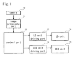
- Fig. 1 is a block diagram showing the configuration of a vehicle headlamp system of one embodiment.
- the vehicle headlamp system of this embodiment is constituted by including a camera 10, an image processing part 11, a control part 12, a laser diode (LD) unit driving part 13, a laser diode (LD) unit 14, an LED unit driving part 15, and an LED unit 16.
- LD laser diode
- LD laser diode
- LED unit driving part 15 LED unit driving part 16
- the control part 12, the LD unit driving part 13, and the LED unit driving part 15 correspond to the "control means.”
- the camera 10 is provided in a predetermined position (such as on a dashboard, in an upper portion of a front windshield, or the like, for example) of the vehicle, and captures images of the space in front of the vehicle.
- the image processing part 11 detects a position of an oncoming vehicle or a preceding vehicle that exists in front of the vehicle (hereinafter simply referred to as "forward vehicle") on the basis of an image of the space in front of the vehicle captured by the camera 10.
- the control part 12 performs control for selectively irradiating light in accordance with a position of the forward vehicle detected by the image processing part 11.
- This control part 12 is configured by executing a predetermined operation program in a computer system that includes a CPU, a ROM, a RAM, and the like, for example.
- the control part 12 sets a certain range that includes a position of a forward vehicle detected by the image processing part 11 as a non-irradiation range, and all other ranges as a light irradiation range, and outputs a control signal for forming a light distribution pattern on the basis of the light irradiation range and non-irradiation range to the LD unit driving part 13 and the LED unit driving part 15.
- the LD unit driving part 13 supplies a driving signal to the LD unit 14 on the basis of the control signal provided from the control part 12.
- the LD unit 14 is constituted by including a laser diode, and selectively irradiates light toward the front of the vehicle on the basis of a driving signal supplied from the LD unit driving part 13.
- the LED unit driving part 15 supplies a driving signal to the LED unit 16 on the basis of the control signal provided from the control part 12.
- the LED unit 16 is constituted by including a pluralty of LEDs (light-emitting diodes), and selectively irradiates light toward the front of the vehicle on the basis of a driving signal supplied from the LED unit driving part 15.
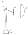
- Fig. 2 is a drawing showing a configuration example of the LD unit.
- the illustrated LD unit 14 is constituted by including a laser diode 20, a condenser lens 21, an MEMS mirror 22, a wavelength conversion member 23, and a projection lens 24.
- the laser diode 20 corresponds to the "first light-emitting element”
- the MEMS (Micro Electro Mechanical Systems) mirror 22 corresponds to the "scanning element.”
- the laser diode 20 is a semiconductor light-emitting element that emits a laser beam of a blue spectral region (an emission wavelength of 450 nm, for example) as an excitation light, for example.
- the MEMS mirror 22 is driven by the LD unit driving part 13 and scans a laser beam that enters from the laser diode 20 in two-dimensional directions (a horizontal direction and a vertical direction) and causes the laser beam to enter the wavelength conversion member 23.
- the wavelength conversion member 23 converts at least a portion of the entered laser beam into a different wavelength.
- the wavelength conversion member 23 includes a fluorescent substance that is excited by the laser beam and produces yellow light. The colors of this yellow light and the laser beam (blue) that is transmitted through the wavelength conversion member 23 are mixed, thereby achieving a pseudo white light.
- the projection lens 24 projects the light emitted from the wavelength conversion member 23 toward the front of the vehicle.
- the laser beam emitted from the laser diode 20 is condensed by a condenser lens 21, and enters the MEMS mirror 22.
- the MEMS mirror 22 scans this laser beam in two-dimensional directions and causes the laser beam to enter the wavelength conversion member 23.
- the scan operation by the MEMS mirror and the on/off driving of the laser diode 20 are synchronized by the control performed by the LD unit driving part 13, thereby forming a light distribution pattern corresponding to the light irradiation range and non-irradiation range set by the control part 12.
- This light distribution pattern is projected in front of the vehicle by the projection lens 24, thereby achieving selective light irradiation in accordance with the position of the forward vehicle.
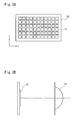
- Figs. 3A and 3B are drawings showing a configuration example of the LED unit.
- the LED unit 16 is constituted by including an LED array 30 and a projection lens 32 (refer to Fig. 3B ).
- the LED array 30 includes a plurality of LEDs 31 arranged in a matrix shape.
- the LEDs 31 may be arranged in a lattice shape such as illustrated or, for example, a zigzag shape.
- the LEDs 31 are individually controlled to turn on by the LED unit driving part 15. It should be noted that each of the LEDs 31 corresponds to the "second light-emitting element.”
- the light emitted from the LEDs 31 of the LED array 30 is projected in front of the vehicle by the projection lens 32.
- the LEDs 31 are individually controlled to turn on and off by the LED unit driving part 15 in correspondence with the light irradiation range and non-irradiation range set by the control part 12, thereby forming a preferred light distribution pattern and achieving selective light irradiation in accordance with the position of the forward vehicle.
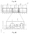
- Figs. 4A and 4B are drawings for explaining the operation details of the vehicle headlamp system.
- Figs. 4A and 4B schematically illustrate a control example of the situation in front of the vehicle and the light distribution pattern corresponding to the forward vehicles.
- a first region a1 is set near the center area in front of the vehicle, and selective light irradiation is performed by the LD unit 14 in this first region a1.
- two forward vehicles exist and thus selective light irradiation is performed by the LD unit 14 in the interior of the first region a1 with the region where these forward vehicles exist set as the non-irradiation range and all other regions set as the light irradiation range.
- Fig. 4B is a drawing showing the first region being enlarged.
- the first region a1 is set as a region that overlaps with a virtual vertical line o presumably in the center area in front of the vehicle using the vehicle as a reference.
- the first region a1 is left-right asymmetrically set across the virtual vertical line o in the center area in front of the vehicle.
- the first region a1 is set so that a width of a right-side region is wider than a width of a left-side region with the virtual vertical line o in the center area in front of the vehicle therebetween.
- the first region a1 in the illustrated example is set in a range within -5° leftward, 10° rightward, 3° upward, and -2° downward when indicated as angles using the center of the vehicle as a reference.
- the settings of the illustrated left-right asymmetrical region presume that legally vehicles travel on the left side of the road and there are many cases in which a forward vehicle (oncoming vehicle) exists in the right-side region, using the vehicle as a reference. In a case where legally vehicles travel on the right side of the road, the regions may be reversely set.
- a second region a2 is set so as to include each region disposed on the left side, right side, and upper side of the first region a1, and selective light irradiation is performed by the LED unit 16 in this second region a2.
- the second region a2 includes a plurality of split regions (light distribution regions) arranged vertically and horizontally, and light irradiation is individually performed by the LED unit 16 in each of the split regions.
- the second region a2 includes six split regions in an upper section, and eight split regions in middle and lower sections, respectively. Each of the split regions increasingly decreases in length (height) in the vertical direction, from the upper section toward the lower section. Further, each of the split regions increasingly decreases in width in the horizontal direction the closer the region is to the first region a1 in middle and lower sections.
- the LED array 30 of the LED unit 16 may further comprise the LEDs 31 capable of irradiating the first region a1. This makes it possible to continue irradiating light in the first region a1 even in the event of failure of the LD unit 14.
- the LD unit 14 capable of higher definition light distribution control is used for the first region a1 corresponding to near the center area in front of the vehicle. Further, because the presumed existing position of the forward vehicles is left-right asymmetrical with respect to the center area in front of the vehicle, the first region a1 is left-right asymmetrically set in correspondence thereto. Further, the LED unit 16 is used for the second region a2 that does not require light distribution control with such a high degree of definition, and each of the split regions is given a relatively large surface area, making it possible to reduce the number of LEDs required and simplify the LED unit 16.
- the region settings for not only the first region a1 but also the second region a2 are left-right asymmetrical.
- a roadside region a21 is set so as to have a wider width than that of an oncoming lane region a22.
- the split regions disposed on the outside are set so as to have a wider width than that of the split regions disposed on the inside (the center area in front of the vehicle).
- the split regions disposed on the outside are set so as to have a wider width than that of the split regions disposed on the inside (the center area in front of the vehicle).
- the number of split regions having a narrow width in the roadside region a21 is set greater than the number of split regions having a narrow width in the oncoming lane region a22.
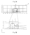
- Figs. 5A and 5B are drawings for explaining another operation details of the vehicle headlamp system.
- the range of the first region a1 may be more narrowly set.
- the first region a1 in the illustrated example is set in a range within -3° leftward, 5° rightward, 3° upward, and -2° downward when indicated as angles using the center of the vehicle as a reference.
- Figs. 6A and 6B are drawings for explaining another operation details of the vehicle headlamp system.
- the range of the first region a1 may be more widely set.
- the first region a1 in the illustrated example is set in a range within -7° leftward, 12° rightward, 3° upward, and -2° downward when indicated as angles using the center of the vehicle as a reference.
- the first region a1 set so widely is effective on a gentle curved road such as illustrated, for example.
- the width of the first region a1 can be variously set as illustrated in Figs. 4A to 6B , allowing variable setup in accordance with road conditions, for example.
- road type information may be acquired from a car navigation system or the like (not illustrated) and, for example, the width of the first region a1 may be set in accordance with each road type of a general road and a highway, and a straight road and a curved road.
- a white line or the like on the road surface may be detected by the image processing part 11, the road conditions may be assessed by the control part 12 in accordance with the detection result, and the width of the first region a1 may be set in accordance with the assessment result.
- the width of the second region a2 in which the light is to be irradiated by the LED unit 16 may also be variably set in accordance with the fluctuation in width of the first region a1.
- the configuration of the LD unit and LED unit is merely an example and not limited thereto.
- the example given for the first light-emitting element in the above is a laser diode, the first light-emitting element is not limited thereto, and may be an LED, for example.
Applications Claiming Priority (1)
| Application Number | Priority Date | Filing Date | Title |
|---|---|---|---|
| JP2015165458A JP6683438B2 (ja) | 2015-08-25 | 2015-08-25 | 車両用前照灯システム |
Publications (2)
| Publication Number | Publication Date |
|---|---|
| EP3135536A1 true EP3135536A1 (de) | 2017-03-01 |
| EP3135536B1 EP3135536B1 (de) | 2021-04-07 |
Family
ID=56550034
Family Applications (1)
| Application Number | Title | Priority Date | Filing Date |
|---|---|---|---|
| EP16179479.7A Active EP3135536B1 (de) | 2015-08-25 | 2016-07-14 | Fahrzeugscheinwerfersystem |
Country Status (2)
| Country | Link |
|---|---|
| EP (1) | EP3135536B1 (de) |
| JP (1) | JP6683438B2 (de) |
Cited By (3)
| Publication number | Priority date | Publication date | Assignee | Title |
|---|---|---|---|---|
| CN109204117A (zh) * | 2017-07-05 | 2019-01-15 | Zkw集团有限责任公司 | 报告眩光的方法和实施这种方法的机动车照明装置 |
| WO2021032432A1 (de) * | 2019-08-21 | 2021-02-25 | Daimler Ag | Verfahren zum entblenden von objekten mittels eines scheinwerfersystems eines kraftfahrzeugs |
| US11338723B2 (en) | 2017-06-09 | 2022-05-24 | Koito Manufacturing Co., Ltd. | Automotive lamp |
Families Citing this family (2)
| Publication number | Priority date | Publication date | Assignee | Title |
|---|---|---|---|---|
| KR101918230B1 (ko) * | 2017-08-16 | 2018-11-14 | 엘지전자 주식회사 | 차량용 램프 및 차량 |
| JP2021024495A (ja) * | 2019-08-08 | 2021-02-22 | 市光工業株式会社 | 車両用前照灯装置 |
Citations (8)
| Publication number | Priority date | Publication date | Assignee | Title |
|---|---|---|---|---|
| DE102007063183A1 (de) * | 2007-12-20 | 2009-06-25 | Daimler Ag | Steuerbarer Scheinwerfer |
| JP2009224039A (ja) | 2008-03-13 | 2009-10-01 | Koito Mfg Co Ltd | 車両用前照灯 |
| JP2010232044A (ja) * | 2009-03-27 | 2010-10-14 | Stanley Electric Co Ltd | 車両用灯具 |
| US20110235349A1 (en) * | 2010-03-25 | 2011-09-29 | Yoshiaki Nakaya | Vehicle light and method for controlling light distribution |
| JP2011198720A (ja) | 2010-03-24 | 2011-10-06 | Stanley Electric Co Ltd | 車両用前照灯 |
| WO2014205466A1 (de) * | 2013-06-25 | 2014-12-31 | Zizala Lichtsysteme Gmbh | Scheinwerfer für fahrzeuge |
| DE102014001201A1 (de) * | 2014-01-29 | 2015-07-30 | Audi Ag | Beleuchtungsvorrichtung für ein Kraftfahrzeug mit zwei Typen von Leuchteinrichtungen |
| EP3028897A1 (de) * | 2014-12-01 | 2016-06-08 | Automotive Lighting Reutlingen GmbH | Verfahren zur erzeugung einer frontlichtverteilung für ein kraftfahrzeug und kfz-beleuchtungseinrichtung |
Family Cites Families (3)
| Publication number | Priority date | Publication date | Assignee | Title |
|---|---|---|---|---|
| JP5199798B2 (ja) * | 2008-09-09 | 2013-05-15 | 株式会社小糸製作所 | 車両用前照灯装置 |
| JP5976345B2 (ja) * | 2012-03-08 | 2016-08-23 | スタンレー電気株式会社 | 車両用前照灯の点灯制御装置及び車両用前照灯システム |
| JP2015011772A (ja) * | 2013-06-26 | 2015-01-19 | スタンレー電気株式会社 | 発光装置、車両用前照灯システム |
-
2015
- 2015-08-25 JP JP2015165458A patent/JP6683438B2/ja active Active
-
2016
- 2016-07-14 EP EP16179479.7A patent/EP3135536B1/de active Active
Patent Citations (8)
| Publication number | Priority date | Publication date | Assignee | Title |
|---|---|---|---|---|
| DE102007063183A1 (de) * | 2007-12-20 | 2009-06-25 | Daimler Ag | Steuerbarer Scheinwerfer |
| JP2009224039A (ja) | 2008-03-13 | 2009-10-01 | Koito Mfg Co Ltd | 車両用前照灯 |
| JP2010232044A (ja) * | 2009-03-27 | 2010-10-14 | Stanley Electric Co Ltd | 車両用灯具 |
| JP2011198720A (ja) | 2010-03-24 | 2011-10-06 | Stanley Electric Co Ltd | 車両用前照灯 |
| US20110235349A1 (en) * | 2010-03-25 | 2011-09-29 | Yoshiaki Nakaya | Vehicle light and method for controlling light distribution |
| WO2014205466A1 (de) * | 2013-06-25 | 2014-12-31 | Zizala Lichtsysteme Gmbh | Scheinwerfer für fahrzeuge |
| DE102014001201A1 (de) * | 2014-01-29 | 2015-07-30 | Audi Ag | Beleuchtungsvorrichtung für ein Kraftfahrzeug mit zwei Typen von Leuchteinrichtungen |
| EP3028897A1 (de) * | 2014-12-01 | 2016-06-08 | Automotive Lighting Reutlingen GmbH | Verfahren zur erzeugung einer frontlichtverteilung für ein kraftfahrzeug und kfz-beleuchtungseinrichtung |
Cited By (6)
| Publication number | Priority date | Publication date | Assignee | Title |
|---|---|---|---|---|
| US11338723B2 (en) | 2017-06-09 | 2022-05-24 | Koito Manufacturing Co., Ltd. | Automotive lamp |
| CN109204117A (zh) * | 2017-07-05 | 2019-01-15 | Zkw集团有限责任公司 | 报告眩光的方法和实施这种方法的机动车照明装置 |
| EP3424779A3 (de) * | 2017-07-05 | 2019-02-06 | ZKW Group GmbH | Verfahren zum melden einer von gegenverkehr ausgehenden blendung und eine kraftfahrzeugbeleuchtungseinrichtung zum ausführen eines solchen verfahrens |
| CN109204117B (zh) * | 2017-07-05 | 2022-03-22 | Zkw集团有限责任公司 | 报告眩光的方法和实施这种方法的机动车照明装置 |
| WO2021032432A1 (de) * | 2019-08-21 | 2021-02-25 | Daimler Ag | Verfahren zum entblenden von objekten mittels eines scheinwerfersystems eines kraftfahrzeugs |
| US11701997B2 (en) | 2019-08-21 | 2023-07-18 | Mercedes-Benz Group AG | Method for eliminating glare from objects by means of a headlamp system of a motor vehicle |
Also Published As
| Publication number | Publication date |
|---|---|
| JP2017043149A (ja) | 2017-03-02 |
| JP6683438B2 (ja) | 2020-04-22 |
| EP3135536B1 (de) | 2021-04-07 |
Similar Documents
| Publication | Publication Date | Title |
|---|---|---|
| JP6265183B2 (ja) | 車両用前照灯装置 | |
| EP3135536B1 (de) | Fahrzeugscheinwerfersystem | |
| JP6751307B2 (ja) | 車両用灯具 | |
| JP6453669B2 (ja) | 車両用前照灯制御装置 | |
| EP2551155B1 (de) | Lichtverteilungssteuerung eines Scheinwerfers | |
| EP3428511B1 (de) | Beleuchtungswerkzeug für fahrzeug | |
| EP2821282A2 (de) | Lichtquellenvorrichtung, Fahrzeugscheinwerfer und Fahrzeugscheinwerfersystem | |
| EP2826667A1 (de) | Fahrzeugscheinwerfer und Fahrzeugscheinwerfersystem | |
| US20080225271A1 (en) | Vehicle Operation Support Method and System | |
| CN109708070B (zh) | 车辆用前照灯装置 | |
| CN107914634B (zh) | 车辆用照明装置 | |
| US11209145B2 (en) | Optical unit | |
| US20160176335A1 (en) | Lighting control device of vehicle headlamp and vehicle headlamp system | |
| JP2019038279A (ja) | 車両用灯具の制御装置、車両用灯具システム | |
| EP3147157B1 (de) | Fahrzeugscheinwerfersystem | |
| JP7057674B2 (ja) | 前照灯装置 | |
| EP3279551A1 (de) | Beleuchtungsvorrichtung | |
| KR20230117231A (ko) | 마이크로 렌즈 어레이 프로젝션 장치, 조명 장치, 및차량 | |
| JP2016083987A (ja) | 車両用照明装置、車載システム | |
| JP7023672B2 (ja) | 車両用灯具、制御装置及び制御方法 | |
| CN114829198A (zh) | 用于控制机动车辆照明系统的方法 | |
| US11850992B2 (en) | Lighting device | |
| CN109196272B (zh) | 用于控制前照灯设备的光分布的方法以及前照灯设备 | |
| US20230151942A1 (en) | Vehicle headlight | |
| WO2016021154A1 (ja) | 照明装置と、それを搭載した自動車 |
Legal Events
| Date | Code | Title | Description |
|---|---|---|---|
| PUAI | Public reference made under article 153(3) epc to a published international application that has entered the european phase |
Free format text: ORIGINAL CODE: 0009012 |
|
| STAA | Information on the status of an ep patent application or granted ep patent |
Free format text: STATUS: THE APPLICATION HAS BEEN PUBLISHED |
|
| AK | Designated contracting states |
Kind code of ref document: A1 Designated state(s): AL AT BE BG CH CY CZ DE DK EE ES FI FR GB GR HR HU IE IS IT LI LT LU LV MC MK MT NL NO PL PT RO RS SE SI SK SM TR |
|
| AX | Request for extension of the european patent |
Extension state: BA ME |
|
| STAA | Information on the status of an ep patent application or granted ep patent |
Free format text: STATUS: REQUEST FOR EXAMINATION WAS MADE |
|
| 17P | Request for examination filed |
Effective date: 20170901 |
|
| RBV | Designated contracting states (corrected) |
Designated state(s): AL AT BE BG CH CY CZ DE DK EE ES FI FR GB GR HR HU IE IS IT LI LT LU LV MC MK MT NL NO PL PT RO RS SE SI SK SM TR |
|
| STAA | Information on the status of an ep patent application or granted ep patent |
Free format text: STATUS: EXAMINATION IS IN PROGRESS |
|
| 17Q | First examination report despatched |
Effective date: 20200604 |
|
| REG | Reference to a national code |
Ref country code: DE Ref legal event code: R079 Ref document number: 602016055530 Country of ref document: DE Free format text: PREVIOUS MAIN CLASS: B60Q0001140000 Ipc: F21S0041143000 |
|
| GRAP | Despatch of communication of intention to grant a patent |
Free format text: ORIGINAL CODE: EPIDOSNIGR1 |
|
| STAA | Information on the status of an ep patent application or granted ep patent |
Free format text: STATUS: GRANT OF PATENT IS INTENDED |
|
| RIC1 | Information provided on ipc code assigned before grant |
Ipc: F21S 41/153 20180101ALI20201019BHEP Ipc: F21S 41/663 20180101ALI20201019BHEP Ipc: F21S 41/143 20180101AFI20201019BHEP Ipc: B60Q 1/14 20060101ALI20201019BHEP Ipc: F21S 41/16 20180101ALI20201019BHEP Ipc: F21S 41/675 20180101ALI20201019BHEP |
|
| INTG | Intention to grant announced |
Effective date: 20201111 |
|
| RIN1 | Information on inventor provided before grant (corrected) |
Inventor name: UCHIDA, MITSUHIRO Inventor name: KITA, YASUSHI |
|
| GRAS | Grant fee paid |
Free format text: ORIGINAL CODE: EPIDOSNIGR3 |
|
| GRAA | (expected) grant |
Free format text: ORIGINAL CODE: 0009210 |
|
| STAA | Information on the status of an ep patent application or granted ep patent |
Free format text: STATUS: THE PATENT HAS BEEN GRANTED |
|
| AK | Designated contracting states |
Kind code of ref document: B1 Designated state(s): AL AT BE BG CH CY CZ DE DK EE ES FI FR GB GR HR HU IE IS IT LI LT LU LV MC MK MT NL NO PL PT RO RS SE SI SK SM TR |
|
| REG | Reference to a national code |
Ref country code: GB Ref legal event code: FG4D |
|
| REG | Reference to a national code |
Ref country code: DE Ref legal event code: R082 Ref document number: 602016055530 Country of ref document: DE Representative=s name: WAGNER & GEYER PARTNERSCHAFT MBB PATENT- UND R, DE |
|
| REG | Reference to a national code |
Ref country code: AT Ref legal event code: REF Ref document number: 1380139 Country of ref document: AT Kind code of ref document: T Effective date: 20210415 Ref country code: CH Ref legal event code: EP |
|
| REG | Reference to a national code |
Ref country code: DE Ref legal event code: R096 Ref document number: 602016055530 Country of ref document: DE |
|
| REG | Reference to a national code |
Ref country code: IE Ref legal event code: FG4D |
|
| REG | Reference to a national code |
Ref country code: LT Ref legal event code: MG9D |
|
| REG | Reference to a national code |
Ref country code: NL Ref legal event code: MP Effective date: 20210407 Ref country code: AT Ref legal event code: MK05 Ref document number: 1380139 Country of ref document: AT Kind code of ref document: T Effective date: 20210407 |
|
| PG25 | Lapsed in a contracting state [announced via postgrant information from national office to epo] |
Ref country code: NL Free format text: LAPSE BECAUSE OF FAILURE TO SUBMIT A TRANSLATION OF THE DESCRIPTION OR TO PAY THE FEE WITHIN THE PRESCRIBED TIME-LIMIT Effective date: 20210407 Ref country code: LT Free format text: LAPSE BECAUSE OF FAILURE TO SUBMIT A TRANSLATION OF THE DESCRIPTION OR TO PAY THE FEE WITHIN THE PRESCRIBED TIME-LIMIT Effective date: 20210407 Ref country code: FI Free format text: LAPSE BECAUSE OF FAILURE TO SUBMIT A TRANSLATION OF THE DESCRIPTION OR TO PAY THE FEE WITHIN THE PRESCRIBED TIME-LIMIT Effective date: 20210407 Ref country code: AT Free format text: LAPSE BECAUSE OF FAILURE TO SUBMIT A TRANSLATION OF THE DESCRIPTION OR TO PAY THE FEE WITHIN THE PRESCRIBED TIME-LIMIT Effective date: 20210407 Ref country code: BG Free format text: LAPSE BECAUSE OF FAILURE TO SUBMIT A TRANSLATION OF THE DESCRIPTION OR TO PAY THE FEE WITHIN THE PRESCRIBED TIME-LIMIT Effective date: 20210707 Ref country code: HR Free format text: LAPSE BECAUSE OF FAILURE TO SUBMIT A TRANSLATION OF THE DESCRIPTION OR TO PAY THE FEE WITHIN THE PRESCRIBED TIME-LIMIT Effective date: 20210407 |
|
| PG25 | Lapsed in a contracting state [announced via postgrant information from national office to epo] |
Ref country code: GR Free format text: LAPSE BECAUSE OF FAILURE TO SUBMIT A TRANSLATION OF THE DESCRIPTION OR TO PAY THE FEE WITHIN THE PRESCRIBED TIME-LIMIT Effective date: 20210708 Ref country code: IS Free format text: LAPSE BECAUSE OF FAILURE TO SUBMIT A TRANSLATION OF THE DESCRIPTION OR TO PAY THE FEE WITHIN THE PRESCRIBED TIME-LIMIT Effective date: 20210807 Ref country code: LV Free format text: LAPSE BECAUSE OF FAILURE TO SUBMIT A TRANSLATION OF THE DESCRIPTION OR TO PAY THE FEE WITHIN THE PRESCRIBED TIME-LIMIT Effective date: 20210407 Ref country code: NO Free format text: LAPSE BECAUSE OF FAILURE TO SUBMIT A TRANSLATION OF THE DESCRIPTION OR TO PAY THE FEE WITHIN THE PRESCRIBED TIME-LIMIT Effective date: 20210707 Ref country code: PT Free format text: LAPSE BECAUSE OF FAILURE TO SUBMIT A TRANSLATION OF THE DESCRIPTION OR TO PAY THE FEE WITHIN THE PRESCRIBED TIME-LIMIT Effective date: 20210809 Ref country code: PL Free format text: LAPSE BECAUSE OF FAILURE TO SUBMIT A TRANSLATION OF THE DESCRIPTION OR TO PAY THE FEE WITHIN THE PRESCRIBED TIME-LIMIT Effective date: 20210407 Ref country code: ES Free format text: LAPSE BECAUSE OF FAILURE TO SUBMIT A TRANSLATION OF THE DESCRIPTION OR TO PAY THE FEE WITHIN THE PRESCRIBED TIME-LIMIT Effective date: 20210407 Ref country code: RS Free format text: LAPSE BECAUSE OF FAILURE TO SUBMIT A TRANSLATION OF THE DESCRIPTION OR TO PAY THE FEE WITHIN THE PRESCRIBED TIME-LIMIT Effective date: 20210407 Ref country code: SE Free format text: LAPSE BECAUSE OF FAILURE TO SUBMIT A TRANSLATION OF THE DESCRIPTION OR TO PAY THE FEE WITHIN THE PRESCRIBED TIME-LIMIT Effective date: 20210407 |
|
| REG | Reference to a national code |
Ref country code: DE Ref legal event code: R097 Ref document number: 602016055530 Country of ref document: DE |
|
| PG25 | Lapsed in a contracting state [announced via postgrant information from national office to epo] |
Ref country code: SK Free format text: LAPSE BECAUSE OF FAILURE TO SUBMIT A TRANSLATION OF THE DESCRIPTION OR TO PAY THE FEE WITHIN THE PRESCRIBED TIME-LIMIT Effective date: 20210407 Ref country code: SM Free format text: LAPSE BECAUSE OF FAILURE TO SUBMIT A TRANSLATION OF THE DESCRIPTION OR TO PAY THE FEE WITHIN THE PRESCRIBED TIME-LIMIT Effective date: 20210407 Ref country code: CZ Free format text: LAPSE BECAUSE OF FAILURE TO SUBMIT A TRANSLATION OF THE DESCRIPTION OR TO PAY THE FEE WITHIN THE PRESCRIBED TIME-LIMIT Effective date: 20210407 Ref country code: DK Free format text: LAPSE BECAUSE OF FAILURE TO SUBMIT A TRANSLATION OF THE DESCRIPTION OR TO PAY THE FEE WITHIN THE PRESCRIBED TIME-LIMIT Effective date: 20210407 Ref country code: EE Free format text: LAPSE BECAUSE OF FAILURE TO SUBMIT A TRANSLATION OF THE DESCRIPTION OR TO PAY THE FEE WITHIN THE PRESCRIBED TIME-LIMIT Effective date: 20210407 Ref country code: RO Free format text: LAPSE BECAUSE OF FAILURE TO SUBMIT A TRANSLATION OF THE DESCRIPTION OR TO PAY THE FEE WITHIN THE PRESCRIBED TIME-LIMIT Effective date: 20210407 |
|
| PLBE | No opposition filed within time limit |
Free format text: ORIGINAL CODE: 0009261 |
|
| STAA | Information on the status of an ep patent application or granted ep patent |
Free format text: STATUS: NO OPPOSITION FILED WITHIN TIME LIMIT |
|
| REG | Reference to a national code |
Ref country code: CH Ref legal event code: PL |
|
| 26N | No opposition filed |
Effective date: 20220110 |
|
| PG25 | Lapsed in a contracting state [announced via postgrant information from national office to epo] |
Ref country code: MC Free format text: LAPSE BECAUSE OF FAILURE TO SUBMIT A TRANSLATION OF THE DESCRIPTION OR TO PAY THE FEE WITHIN THE PRESCRIBED TIME-LIMIT Effective date: 20210407 |
|
| REG | Reference to a national code |
Ref country code: BE Ref legal event code: MM Effective date: 20210731 |
|
| PG25 | Lapsed in a contracting state [announced via postgrant information from national office to epo] |
Ref country code: LI Free format text: LAPSE BECAUSE OF NON-PAYMENT OF DUE FEES Effective date: 20210731 Ref country code: CH Free format text: LAPSE BECAUSE OF NON-PAYMENT OF DUE FEES Effective date: 20210731 |
|
| PG25 | Lapsed in a contracting state [announced via postgrant information from national office to epo] |
Ref country code: IS Free format text: LAPSE BECAUSE OF FAILURE TO SUBMIT A TRANSLATION OF THE DESCRIPTION OR TO PAY THE FEE WITHIN THE PRESCRIBED TIME-LIMIT Effective date: 20210807 Ref country code: LU Free format text: LAPSE BECAUSE OF NON-PAYMENT OF DUE FEES Effective date: 20210714 Ref country code: AL Free format text: LAPSE BECAUSE OF FAILURE TO SUBMIT A TRANSLATION OF THE DESCRIPTION OR TO PAY THE FEE WITHIN THE PRESCRIBED TIME-LIMIT Effective date: 20210407 |
|
| PG25 | Lapsed in a contracting state [announced via postgrant information from national office to epo] |
Ref country code: IT Free format text: LAPSE BECAUSE OF FAILURE TO SUBMIT A TRANSLATION OF THE DESCRIPTION OR TO PAY THE FEE WITHIN THE PRESCRIBED TIME-LIMIT Effective date: 20210407 Ref country code: IE Free format text: LAPSE BECAUSE OF NON-PAYMENT OF DUE FEES Effective date: 20210714 Ref country code: BE Free format text: LAPSE BECAUSE OF NON-PAYMENT OF DUE FEES Effective date: 20210731 |
|
| PG25 | Lapsed in a contracting state [announced via postgrant information from national office to epo] |
Ref country code: HU Free format text: LAPSE BECAUSE OF FAILURE TO SUBMIT A TRANSLATION OF THE DESCRIPTION OR TO PAY THE FEE WITHIN THE PRESCRIBED TIME-LIMIT; INVALID AB INITIO Effective date: 20160714 |
|
| PG25 | Lapsed in a contracting state [announced via postgrant information from national office to epo] |
Ref country code: CY Free format text: LAPSE BECAUSE OF FAILURE TO SUBMIT A TRANSLATION OF THE DESCRIPTION OR TO PAY THE FEE WITHIN THE PRESCRIBED TIME-LIMIT Effective date: 20210407 |
|
| PGFP | Annual fee paid to national office [announced via postgrant information from national office to epo] |
Ref country code: FR Payment date: 20230620 Year of fee payment: 8 |
|
| PGFP | Annual fee paid to national office [announced via postgrant information from national office to epo] |
Ref country code: GB Payment date: 20230601 Year of fee payment: 8 |
|
| PGFP | Annual fee paid to national office [announced via postgrant information from national office to epo] |
Ref country code: DE Payment date: 20230531 Year of fee payment: 8 |
|
| PG25 | Lapsed in a contracting state [announced via postgrant information from national office to epo] |
Ref country code: MK Free format text: LAPSE BECAUSE OF FAILURE TO SUBMIT A TRANSLATION OF THE DESCRIPTION OR TO PAY THE FEE WITHIN THE PRESCRIBED TIME-LIMIT Effective date: 20210407 |