EP3135510A1 - Vorrichtung zur steuerung des luftdrucks in luftreifen eines anhängers - Google Patents
Vorrichtung zur steuerung des luftdrucks in luftreifen eines anhängers Download PDFInfo
- Publication number
- EP3135510A1 EP3135510A1 EP16180561.9A EP16180561A EP3135510A1 EP 3135510 A1 EP3135510 A1 EP 3135510A1 EP 16180561 A EP16180561 A EP 16180561A EP 3135510 A1 EP3135510 A1 EP 3135510A1
- Authority
- EP
- European Patent Office
- Prior art keywords
- compressed air
- compressor
- side parts
- trailer
- air reservoir
- Prior art date
- Legal status (The legal status is an assumption and is not a legal conclusion. Google has not performed a legal analysis and makes no representation as to the accuracy of the status listed.)
- Granted
Links
- 238000010276 construction Methods 0.000 abstract 1
- 230000008901 benefit Effects 0.000 description 3
- 230000008878 coupling Effects 0.000 description 2
- 238000010168 coupling process Methods 0.000 description 2
- 238000005859 coupling reaction Methods 0.000 description 2
- 238000009420 retrofitting Methods 0.000 description 2
- 230000006978 adaptation Effects 0.000 description 1
- 230000005540 biological transmission Effects 0.000 description 1
- 230000002349 favourable effect Effects 0.000 description 1
- 239000003351 stiffener Substances 0.000 description 1
Images


Classifications
-
- B—PERFORMING OPERATIONS; TRANSPORTING
- B41—PRINTING; LINING MACHINES; TYPEWRITERS; STAMPS
- B41K—STAMPS; STAMPING OR NUMBERING APPARATUS OR DEVICES
- B41K1/00—Portable hand-operated devices without means for supporting or locating the articles to be stamped, i.e. hand stamps; Inking devices or other accessories therefor
- B41K1/36—Details
- B41K1/38—Inking devices; Stamping surfaces
- B41K1/40—Inking devices operated by stamping movement
- B41K1/42—Inking devices operated by stamping movement with pads or rollers movable for inking
-
- B—PERFORMING OPERATIONS; TRANSPORTING
- B60—VEHICLES IN GENERAL
- B60C—VEHICLE TYRES; TYRE INFLATION; TYRE CHANGING; CONNECTING VALVES TO INFLATABLE ELASTIC BODIES IN GENERAL; DEVICES OR ARRANGEMENTS RELATED TO TYRES
- B60C23/00—Devices for measuring, signalling, controlling, or distributing tyre pressure or temperature, specially adapted for mounting on vehicles; Arrangement of tyre inflating devices on vehicles, e.g. of pumps or of tanks; Tyre cooling arrangements
- B60C23/10—Arrangement of tyre-inflating pumps mounted on vehicles
- B60C23/14—Arrangement of tyre-inflating pumps mounted on vehicles operated by the prime mover of the vehicle
-
- B—PERFORMING OPERATIONS; TRANSPORTING
- B41—PRINTING; LINING MACHINES; TYPEWRITERS; STAMPS
- B41K—STAMPS; STAMPING OR NUMBERING APPARATUS OR DEVICES
- B41K1/00—Portable hand-operated devices without means for supporting or locating the articles to be stamped, i.e. hand stamps; Inking devices or other accessories therefor
- B41K1/02—Portable hand-operated devices without means for supporting or locating the articles to be stamped, i.e. hand stamps; Inking devices or other accessories therefor with one or more flat stamping surfaces having fixed images
- B41K1/04—Portable hand-operated devices without means for supporting or locating the articles to be stamped, i.e. hand stamps; Inking devices or other accessories therefor with one or more flat stamping surfaces having fixed images with multiple stamping surfaces; with stamping surfaces replaceable as a whole
-
- B—PERFORMING OPERATIONS; TRANSPORTING
- B41—PRINTING; LINING MACHINES; TYPEWRITERS; STAMPS
- B41K—STAMPS; STAMPING OR NUMBERING APPARATUS OR DEVICES
- B41K1/00—Portable hand-operated devices without means for supporting or locating the articles to be stamped, i.e. hand stamps; Inking devices or other accessories therefor
- B41K1/36—Details
- B41K1/38—Inking devices; Stamping surfaces
- B41K1/40—Inking devices operated by stamping movement
-
- B—PERFORMING OPERATIONS; TRANSPORTING
- B41—PRINTING; LINING MACHINES; TYPEWRITERS; STAMPS
- B41K—STAMPS; STAMPING OR NUMBERING APPARATUS OR DEVICES
- B41K1/00—Portable hand-operated devices without means for supporting or locating the articles to be stamped, i.e. hand stamps; Inking devices or other accessories therefor
- B41K1/36—Details
- B41K1/56—Handles
-
- B—PERFORMING OPERATIONS; TRANSPORTING
- B60—VEHICLES IN GENERAL
- B60C—VEHICLE TYRES; TYRE INFLATION; TYRE CHANGING; CONNECTING VALVES TO INFLATABLE ELASTIC BODIES IN GENERAL; DEVICES OR ARRANGEMENTS RELATED TO TYRES
- B60C23/00—Devices for measuring, signalling, controlling, or distributing tyre pressure or temperature, specially adapted for mounting on vehicles; Arrangement of tyre inflating devices on vehicles, e.g. of pumps or of tanks; Tyre cooling arrangements
- B60C23/10—Arrangement of tyre-inflating pumps mounted on vehicles
-
- B—PERFORMING OPERATIONS; TRANSPORTING
- B60—VEHICLES IN GENERAL
- B60C—VEHICLE TYRES; TYRE INFLATION; TYRE CHANGING; CONNECTING VALVES TO INFLATABLE ELASTIC BODIES IN GENERAL; DEVICES OR ARRANGEMENTS RELATED TO TYRES
- B60C23/00—Devices for measuring, signalling, controlling, or distributing tyre pressure or temperature, specially adapted for mounting on vehicles; Arrangement of tyre inflating devices on vehicles, e.g. of pumps or of tanks; Tyre cooling arrangements
- B60C23/16—Arrangement of air tanks mounted on vehicles
Definitions
- the invention relates to a device for controlling the air pressure in pneumatic tires of a trailer of an agricultural tractor with an acted upon by a compressor compressed air reservoir and with a connectable to the compressed air reservoir, via control valves connected to the pneumatic tire air distributor.
- the invention is therefore based on the object to make simple constructive arrangements also from the point of view of a possible retrofitting to be able to adapt the pressure of the pneumatic tires of trailers of an agricultural tractor to the respective requirements quickly.
- the invention solves this problem in that the compressor with a connectable as a front weight to the agricultural tractor unit forming compressed air storage a compressed air tank with two by a center section connected side parts and that the compressor between the two side parts is arranged on the central portion of the compressed air tank.
- the design of the compressed air tank with two connected by a central portion side parts in conjunction with the arrangement of the compressor between the two side panels on the central portion of the compressed air tank allows a good adaptation of the unit to the shape of conventional front weights for agricultural tractors.
- the compressor arrangement also leaves the drive of the compressor open either via a hydraulic motor or a PTO of the agricultural tractor.
- the compressed air tank In the region of the agricultural tractor facing rear wall of the side parts and on a connecting the side parts, bridging the center section carrier arranged in recessed recesses pivot axes for connecting the compressed air tank to a front hitch of the tractor, so the unit formed from the compressed air reservoir and the compressor as usual a standard front weight can be connected to the three-point link of the front hitch of the agricultural tractor.
- the compressive strength of the compressed air tank of the compressed air reservoir is of particular importance.
- the relevant requirements can be met in an advantageous manner when the provided with a floor, a ceiling and a jacket compressed air tank is stiffened on the one hand by shelves and on the other hand by the shelves interspersing pillars between the floor and the ceiling.
- the increased weight of the compressed air tank through this stiffening benefits the function of the unit consisting of compressed air reservoir and compressor as a front weight.
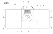
- the device shown forms a unit formed from a compressed air reservoir 1 and a compressor 2 in the form of a front weight for an agricultural tractor, in particular for a tractor with a front lifting.
- the compressed air reservoir 1 comprises a compressed air tank which has two side parts 3 and a middle section 4 connecting these side parts 3.
- the compressor 2 is mounted between the two side parts 3 of the compressed-air reservoir 1 on the center section 4 and is covered by a carrier 6 bridging the middle section 4 and connecting the two side parts 3 in the region of their cover 5.
- the provided between a bottom 7 and the ceiling 5 jacket 8 of the compressed air tank is stiffened by 9 parallel to the bottom shelves 9.
- 5 posts 10 are provided between the bottom 7 and the ceiling, which enforce the shelves 9 with clearance, so that the compressed air tank has a sufficient pressure for even higher air pressure and through the stiffeners by means of the shelves 9 and the uprights 10 for the function as Front weight gets sufficient mass.
- the compressed air reservoir 1 is provided with articulation axes 11 and 12.
- the arrangement is made such that the pivot axes 11 are arranged for the two lower links of the front lift in recessed recesses 13 in the rear wall of the side parts 3 facing the tractor.
- the articulation axis 12 for the upper link of the front lifting mechanism is provided in a corresponding recess of the carrier 6.
- the assembly of compressor 2 and compressed air reservoir 1 can thus be included as any other front weight of the front hitch of the agricultural tractor, the compressor 2 can be driven by a PTO of the agricultural tractor, if not a separate drive, such as a hydraulic motor, is provided for this purpose.
- the compressed air tank 1 To control the pressure of the pneumatic tires of a trailer, only the compressed air tank 1 needs to be connected via a corresponding compressed air coupling with the air pressure distributor provided on the trailer in order to pass through a appropriate control of the compressed air distributor to be able to adapt the pressure in the pneumatic tire of the trailer to the respective requirements.
Landscapes
- Engineering & Computer Science (AREA)
- Mechanical Engineering (AREA)
- Compressors, Vaccum Pumps And Other Relevant Systems (AREA)
Abstract
Description
- Die Erfindung bezieht sich auf eine Vorrichtung zur Steuerung des Luftdrucks in Luftreifen eines Anhängers einer landwirtschaftlichen Zugmaschine mit einem von einem Verdichter beaufschlagbaren Druckluftspeicher und mit einem an den Druckluftspeicher anschließbaren, über Steuerventile mit den Luftreifen verbundenen Druckluftverteiler.
- Um beim Befahren nicht befestigter, landwirtschaftlich genutzter Flächen den Auflagedruck von Zugmaschinen und Anhängern zu verringern, wird Luft aus den Luftreifen dieser Fahrzeuge ausgelassen. Diese Maßnahme erfordert allerdings eine Erhöhung des Luftdrucks in den Luftreifen für Fahrten auf befestigten Flächen, was insbesondere für Anhänger zu Schwierigkeiten führt, weil beispielsweise das für pneumatische Bremsanlagen vorgesehene Druckluftsystem hierfür aufgrund des begrenzten Bremsluftdrucks nicht eingesetzt werden kann. Es wurde daher vorgeschlagen (
WO 2010/091843 A1 ), für die Steuerung des Luftdrucks in den Luftreifen von Anhängern einen gesonderten Verdichter am Zugfahrzeug vorzusehen und mithilfe dieses Verdichters einen Druckluftspeicher auf dem Anhänger über eine Druckluftkupplung zu beaufschlagen, sodass der Druck in den Luftreifen des Anhängers über einen an diesen Druckluftspeicher angeschlossenen Druckluftverteiler gesteuert werden kann. Nachteilig ist allerdings, dass jeder Anhänger mit einem solchen Druckluftspeicher ausgerüstet sein muss und dass ein Nachrüsten landwirtschaftlicher Zugmaschinen mit einem zusätzlichen Verdichter für höhere Luftdrücke wegen der im Allgemeinen gedrängten Platzverhältnisse Schwierigkeiten macht. - Damit eine Baueinheit aus Verdichter und Druckluftspeicher an eine landwirtschaftliche Zugmaschine in einfacher Weise angebaut und über eine Zapfwelle angetrieben werden kann, ist es außerdem bekannt (
IT 1245655 B - Der Erfindung liegt somit die Aufgabe zugrunde, auch unter dem Gesichtspunkt eines möglichen Nachrüstens einfache konstruktive Vorkehrungen zu treffen, den Druck der Luftreifen von Anhängern einer landwirtschaftlichen Zugmaschine an die jeweiligen Anforderungen rasch anpassen zu können.
- Ausgehend von einer Vorrichtung der eingangs geschilderten Art zur Steuerung des Luftdrucks in Luftreifen eines Anhängers einer landwirtschaftlichen Zugmaschine löst die Erfindung die gestellte Aufgabe dadurch, dass der mit dem Verdichter eine als Frontgewicht an die landwirtschaftliche Zugmaschine anschließbare Baueinheit bildende Druckluftspeicher einen Druckluftbehälter mit zwei durch einen Mittenabschnitt verbundenen Seitenteilen umfasst und dass der Verdichter zwischen den beiden Seitenteilen auf dem Mittenabschnitt des Druckluftbehälters angeordnet ist.
- Durch die Zusammenfassung des Verdichters und des Druckluftspeichers zu einer Baueinheit auf der landwirtschaftlichen Zugmaschine wird zunächst der Vorteil erreicht, dass auf den Anhängern keine Druckluftspeicher vorgesehen werden müssen und daher im Bedarfsfall bei allen Anhängern, deren Luftreifen über einen Druckluftverteiler mit Druckluft versorgt werden können, in einfacher Weise eine Steuerung des Luftdrucks in den Luftreifen möglich wird. Da die Baueinheit aus Verdichter und Druckluftspeicher als Frontgewicht eingesetzt wird, das in üblicher Art an die landwirtschaftliche Zugmaschine angeschlossen werden kann, entfallen sonst auftretende Schwierigkeiten, die mit der Unterbringung ausreichend großer Druckluftspeicher und der für sie vorgesehenen Verdichter verbunden sind, und zwar mit dem Vorteil einer günstigen Lastverteilung. Die Bauweise des Druckluftbehälters mit zwei durch einen Mittenabschnitt verbundenen Seitenteilen in Verbindung mit der Anordnung des Verdichters zwischen den beiden Seitenteilen auf dem Mittenabschnitt des Druckluftbehälters erlaubt eine gute Anpassung der Baueinheit an die Form üblicher Frontgewichte für landwirtschaftliche Zugmaschinen. Die Verdichteranordnung lässt außerdem den Antrieb des Verdichters entweder über einen Hydraulikmotor oder eine Zapfwelle der landwirtschaftlichen Zugmaschine offen.
- Zum Anschluss der Baueinheit an ein Fronthubwerk der Zugmaschine kann der Druckluftbehälter im Bereich der der landwirtschaftlichen Zugmaschine zugekehrten Rückwand der Seitenteile und auf einem die Seitenteile verbindenden, den Mittenabschnitt überbrückenden Träger in einspringenden Ausnehmungen angeordnete Anlenkachsen zum Anschließen des Druckluftbehälters an ein Fronthubwerk der Zugmaschine aufweisen, sodass die aus dem Druckluftspeicher und dem Verdichter gebildete Baueinheit wie sonst ein übliches Frontgewicht an die Dreipunktlenker des Fronthubwerks der landwirtschaftlichen Zugmaschine angeschlossen werden kann.
- Da zur Druckluftversorgung der Luftreifen von Anhängern landwirtschaftlicher Zugmaschinen mit vergleichsweise hohen Luftdrücken gearbeitet werden muss, kommt der Druckfestigkeit des Druckluftbehälters des Druckluftspeichers eine besondere Bedeutung zu. Den diesbezüglichen Anforderungen kann in vorteilhafter Weise entsprochen werden, wenn der mit einem Boden, einer Decke und einem Mantel versehene Druckluftbehälter einerseits durch Fachböden und anderseits durch die Fachböden durchsetzende Steher zwischen dem Boden und der Decke ausgesteift wird. Das durch diese Aussteifung vergrößerte Gewicht des Druckluftbehälters kommt der Funktion der Baueinheit aus Druckluftspeicher und Verdichter als Frontgewicht zugute.
- In der Zeichnung ist der Erfindungsgegenstand beispielsweise dargestellt. Es zeigen
-
Fig. 1 eine erfindungsgemäße Vorrichtung in einer schematischen Vorderansicht, -
Fig. 2 diese Vorrichtung in einem Schnitt nach der Linie II-II derFig. 1 , -
Fig. 3 einen Schnitt nach der Linie III-III derFig. 2 und -
Fig. 4 die Vorrichtung in einer Seitenansicht. - Die dargestellte Vorrichtung bildet eine aus einem Druckluftspeicher 1 und einem Verdichter 2 gebildete Baueinheit in Form eines Frontgewichts für eine landwirtschaftliche Zugmaschine, insbesondere für einen Ackerschlepper mit einem Fronthubwerk. Der Druckluftspeicher 1 umfasst einen Druckluftbehälter, der zwei Seitenteile 3 und einen diese Seitenteile 3 verbindenden Mittenabschnitt 4 aufweist. Der Verdichter 2 ist zwischen den beiden Seitenteilen 3 des Druckluftspeichers 1 auf dem Mittenabschnitt 4 gelagert und wird durch einen den Mittenabschnitt 4 überbrückenden, die beiden Seitenteile 3 im Bereich ihrer Decke 5 verbindenden Träger 6 abgedeckt.
- Der zwischen einem Boden 7 und der Decke 5 vorgesehene Mantel 8 des Druckluftbehälters wird durch zum Boden 7 parallele Fachböden 9 ausgesteift. Zusätzlich sind zwischen dem Boden 7 und der Decke 5 Steher 10 vorgesehen, die die Fachböden 9 mit Spiel durchsetzen, sodass der Druckluftbehälter eine auch für höhere Luftdrücke ausreichende Druckfestigkeit aufweist und durch die Aussteifungen mittels der Fachböden 9 und der Steher 10 eine für die Funktion als Frontgewicht ausreichende Masse erhält.
- Zum Anschließen der aus dem Druckluftspeicher 1 und dem Verdichter 2 gebildeten Baueinheit an ein Fronthubwerk einer landwirtschaftlichen Zugmaschine ist der Druckluftspeicher 1 mit Anlenkachsen 11 und 12 versehen. Die Anordnung ist dabei so getroffen, dass die Anlenkachsen 11 für die beiden Unterlenker des Fronthubwerks in einspringenden Ausnehmungen 13 in der der Zugmaschine zugekehrten Rückwand der Seitenteile 3 angeordnet sind. Die Anlenkachse 12 für den Oberlenker des Fronthubwerks ist in einer entsprechenden Ausnehmung des Trägers 6 vorgesehen. Die Baueinheit aus Verdichter 2 und Druckluftspeicher 1 kann somit wie jedes andere Frontgewicht vom Fronthubwerk der landwirtschaftlichen Zugmaschine aufgenommen werden, wobei der Verdichter 2 von einer Zapfwelle der landwirtschaftlichen Zugmaschine angetrieben werden kann, wenn nicht hierfür ein gesonderter Antrieb, beispielsweise ein Hydraulikmotor, vorgesehen wird.
- Zur Steuerung des Drucks der Luftreifen eines Anhängers braucht lediglich der Druckluftbehälter 1 über eine entsprechende Druckluftkupplung mit dem auf dem Anhänger vorgesehenen Druckluftverteiler verbunden zu werden, um durch eine geeignete Ansteuerung des Druckluftverteilers den Druck in den Luftreifen des Anhängers den jeweiligen Anforderungen anpassen zu können.
Claims (3)
- Vorrichtung zur Steuerung des Luftdrucks in Luftreifen eines Anhängers einer landwirtschaftlichen Zugmaschine mit einem von einem Verdichter (2) beaufschlagbaren Druckluftspeicher (1) und mit einem an den Druckluftspeicher (1) anschließbaren, über Steuerventile mit den Luftreifen verbundenen Druckluftverteiler, dadurch gekennzeichnet, dass der mit dem Verdichter (2) eine als Frontgewicht an die landwirtschaftliche Zugmaschine anschließbare Baueinheit bildende Druckluftspeicher (1) einen Druckluftbehälter mit zwei durch einen Mittenabschnitt (4) verbundenen Seitenteilen (3) umfasst und dass der Verdichter (2) zwischen den beiden Seitenteilen (3) auf dem Mittenabschnitt (4) des Druckluftbehälters angeordnet ist.
- Vorrichtung nach Anspruch 1, dadurch gekennzeichnet, dass der Druckluftbehälter im Bereich der der landwirtschaftlichen Zugmaschine zugekehrten Rückwand der Seitenteile (3) und auf einem die Seitenteile (3) verbindenden, den Mittenabschnitt (4) überbrückenden Träger (6) in einspringenden Ausnehmungen (13) angeordnete Anlenkachsen (11, 12) zum Anschließen des Druckluftbehälters an ein Fronthubwerk der Zugmaschine aufweist.
- Vorrichtung nach Anspruch 1 oder 2, dadurch gekennzeichnet, dass der mit einem Boden (7), einer Decke (5) und einem Mantel (8) versehene Druckluftbehälter einerseits durch Fachböden (9) und anderseits durch die Fachböden (9) durchsetzende Steher (10) zwischen dem Boden (7) und der Decke (5) ausgesteift ist.
Priority Applications (2)
| Application Number | Priority Date | Filing Date | Title |
|---|---|---|---|
| PL16180561T PL3135510T3 (pl) | 2015-08-27 | 2016-07-21 | Urządzenie do sterowania ciśnieniem powietrza w oponach pneumatycznych przyczepy |
| SI201630053T SI3135510T1 (sl) | 2015-08-27 | 2016-07-21 | Naprava za krmiljenje zračnega tlaka v pnevamatikah prikolice |
Applications Claiming Priority (1)
| Application Number | Priority Date | Filing Date | Title |
|---|---|---|---|
| ATA50743/2015A AT517102B1 (de) | 2015-08-27 | 2015-08-27 | Vorrichtung zur Steuerung des Luftdrucks in Luftreifen eines Anhängers |
Publications (2)
| Publication Number | Publication Date |
|---|---|
| EP3135510A1 true EP3135510A1 (de) | 2017-03-01 |
| EP3135510B1 EP3135510B1 (de) | 2018-03-28 |
Family
ID=56411335
Family Applications (1)
| Application Number | Title | Priority Date | Filing Date |
|---|---|---|---|
| EP16180561.9A Active EP3135510B1 (de) | 2015-08-27 | 2016-07-21 | Vorrichtung zur steuerung des luftdrucks in luftreifen eines anhängers |
Country Status (5)
| Country | Link |
|---|---|
| EP (1) | EP3135510B1 (de) |
| AT (1) | AT517102B1 (de) |
| HU (1) | HUE038119T2 (de) |
| PL (1) | PL3135510T3 (de) |
| SI (1) | SI3135510T1 (de) |
Citations (3)
| Publication number | Priority date | Publication date | Assignee | Title |
|---|---|---|---|---|
| DE3806322A1 (de) * | 1988-02-27 | 1989-09-07 | Konrad Biberger | Vorrichtung zur einstellung des reifendruckes an fahrzeugen |
| IT1245655B (it) * | 1990-12-07 | 1994-10-03 | Dari Di Dari Davide & C S N C | Attacco componibile di un gruppo compressore ad un trattore. |
| WO2011033015A1 (en) * | 2009-09-16 | 2011-03-24 | Agco Gmbh | Tyre inflation system for a tractor |
-
2015
- 2015-08-27 AT ATA50743/2015A patent/AT517102B1/de active
-
2016
- 2016-07-21 HU HUE16180561A patent/HUE038119T2/hu unknown
- 2016-07-21 SI SI201630053T patent/SI3135510T1/sl unknown
- 2016-07-21 PL PL16180561T patent/PL3135510T3/pl unknown
- 2016-07-21 EP EP16180561.9A patent/EP3135510B1/de active Active
Patent Citations (3)
| Publication number | Priority date | Publication date | Assignee | Title |
|---|---|---|---|---|
| DE3806322A1 (de) * | 1988-02-27 | 1989-09-07 | Konrad Biberger | Vorrichtung zur einstellung des reifendruckes an fahrzeugen |
| IT1245655B (it) * | 1990-12-07 | 1994-10-03 | Dari Di Dari Davide & C S N C | Attacco componibile di un gruppo compressore ad un trattore. |
| WO2011033015A1 (en) * | 2009-09-16 | 2011-03-24 | Agco Gmbh | Tyre inflation system for a tractor |
Also Published As
| Publication number | Publication date |
|---|---|
| SI3135510T1 (sl) | 2018-10-30 |
| EP3135510B1 (de) | 2018-03-28 |
| AT517102A4 (de) | 2016-11-15 |
| PL3135510T3 (pl) | 2018-11-30 |
| HUE038119T2 (hu) | 2018-09-28 |
| AT517102B1 (de) | 2016-11-15 |
Similar Documents
| Publication | Publication Date | Title |
|---|---|---|
| DE102007008156B4 (de) | Luftfederungseinrichtung mit ausschließlich druckmittelbetätigten Steuerventilen und einer Höhenbegrenzungseinrichtung | |
| EP2380422B1 (de) | Hydraulische Anordnung | |
| DE202016101279U1 (de) | Antriebseinheit | |
| EP3730363B1 (de) | Hydrauliksystem und fahrzeug | |
| DE202013004660U1 (de) | Fahrzeuganhänger mit integriertem Luftkessel | |
| EP2272736A1 (de) | Steuerbare Achse für einen Anhänger | |
| DE2056634A1 (de) | Luftfederung, insbesondere für Kraftfahrzeuge | |
| DE102010054108A1 (de) | Ventilanordnung zur Steuerung eines Zusatz-Lenksystems bei mehrachsigen Fahrzeugen, insbesondere Mobilkranen | |
| EP2227412B1 (de) | Hydraulisches lenksystem für fahrzeuganhänger | |
| DE102012100699A1 (de) | Zugdeichsel für Fahrzeuganhänger | |
| EP2772371B1 (de) | Anhängefahrzeug mit Tandemachse | |
| DE102007020744A1 (de) | Hydraulikzylinder | |
| AT517102B1 (de) | Vorrichtung zur Steuerung des Luftdrucks in Luftreifen eines Anhängers | |
| AT515172A1 (de) | Anhänger | |
| DE102018002488A1 (de) | Bremssystem eines Fahrzeugzuges | |
| DE102012015554B4 (de) | Muldenkipper mit einer Kippermulde | |
| EP2025595B1 (de) | Schleppfahrzeug für Flugzeuge | |
| DE102017104811A1 (de) | Kopplungseinrichtung eines Routenzugs | |
| DE102006004930A1 (de) | Mit einem Zugfahrzeug über einen Schwanenhals kuppelbares Schwerstlastfahrzeug | |
| DE880854C (de) | Anhaengerkupplung fuer Lastkraftzuege | |
| DE1943907A1 (de) | Kupplungsvorrichtung fuer Schlepper | |
| DE102007006265A1 (de) | Sattelzugmaschine eines Sattelkraftwagens | |
| DE102018122718B4 (de) | Nutzfahrzeug mit absenkbarem Ladeboden | |
| DE1500074C3 (de) | Hdraulfscher Druckregler | |
| DE102006032348A1 (de) | Ventilanordnung für eine Fahrzeug-Luftfederung sowie Ventilblock |
Legal Events
| Date | Code | Title | Description |
|---|---|---|---|
| PUAI | Public reference made under article 153(3) epc to a published international application that has entered the european phase |
Free format text: ORIGINAL CODE: 0009012 |
|
| AK | Designated contracting states |
Kind code of ref document: A1 Designated state(s): AL AT BE BG CH CY CZ DE DK EE ES FI FR GB GR HR HU IE IS IT LI LT LU LV MC MK MT NL NO PL PT RO RS SE SI SK SM TR |
|
| AX | Request for extension of the european patent |
Extension state: BA ME |
|
| 17P | Request for examination filed |
Effective date: 20170714 |
|
| RBV | Designated contracting states (corrected) |
Designated state(s): AL AT BE BG CH CY CZ DE DK EE ES FI FR GB GR HR HU IE IS IT LI LT LU LV MC MK MT NL NO PL PT RO RS SE SI SK SM TR |
|
| RIC1 | Information provided on ipc code assigned before grant |
Ipc: B60C 23/14 20060101ALI20170929BHEP Ipc: B60C 23/10 20060101ALI20170929BHEP Ipc: B60C 23/16 20060101AFI20170929BHEP |
|
| GRAP | Despatch of communication of intention to grant a patent |
Free format text: ORIGINAL CODE: EPIDOSNIGR1 |
|
| INTG | Intention to grant announced |
Effective date: 20171114 |
|
| GRAS | Grant fee paid |
Free format text: ORIGINAL CODE: EPIDOSNIGR3 |
|
| GRAA | (expected) grant |
Free format text: ORIGINAL CODE: 0009210 |
|
| AK | Designated contracting states |
Kind code of ref document: B1 Designated state(s): AL AT BE BG CH CY CZ DE DK EE ES FI FR GB GR HR HU IE IS IT LI LT LU LV MC MK MT NL NO PL PT RO RS SE SI SK SM TR |
|
| RAP1 | Party data changed (applicant data changed or rights of an application transferred) |
Owner name: SCHAUSBERGER, HEINRICH Owner name: PREUNER, MICHAEL |
|
| REG | Reference to a national code |
Ref country code: GB Ref legal event code: FG4D Free format text: NOT ENGLISH |
|
| RIN1 | Information on inventor provided before grant (corrected) |
Inventor name: SCHAUSBERGER, HEINRICH Inventor name: PREUNER, MICHAEL |
|
| REG | Reference to a national code |
Ref country code: CH Ref legal event code: EP |
|
| REG | Reference to a national code |
Ref country code: AT Ref legal event code: REF Ref document number: 983064 Country of ref document: AT Kind code of ref document: T Effective date: 20180415 |
|
| REG | Reference to a national code |
Ref country code: IE Ref legal event code: FG4D Free format text: LANGUAGE OF EP DOCUMENT: GERMAN |
|
| REG | Reference to a national code |
Ref country code: DE Ref legal event code: R096 Ref document number: 502016000782 Country of ref document: DE |
|
| REG | Reference to a national code |
Ref country code: RO Ref legal event code: EPE |
|
| REG | Reference to a national code |
Ref country code: CH Ref legal event code: NV Representative=s name: E. BLUM AND CO. AG PATENT- UND MARKENANWAELTE , CH |
|
| REG | Reference to a national code |
Ref country code: NL Ref legal event code: FP |
|
| REG | Reference to a national code |
Ref country code: FR Ref legal event code: PLFP Year of fee payment: 3 |
|
| PG25 | Lapsed in a contracting state [announced via postgrant information from national office to epo] |
Ref country code: NO Free format text: LAPSE BECAUSE OF FAILURE TO SUBMIT A TRANSLATION OF THE DESCRIPTION OR TO PAY THE FEE WITHIN THE PRESCRIBED TIME-LIMIT Effective date: 20180628 Ref country code: HR Free format text: LAPSE BECAUSE OF FAILURE TO SUBMIT A TRANSLATION OF THE DESCRIPTION OR TO PAY THE FEE WITHIN THE PRESCRIBED TIME-LIMIT Effective date: 20180328 Ref country code: FI Free format text: LAPSE BECAUSE OF FAILURE TO SUBMIT A TRANSLATION OF THE DESCRIPTION OR TO PAY THE FEE WITHIN THE PRESCRIBED TIME-LIMIT Effective date: 20180328 Ref country code: LT Free format text: LAPSE BECAUSE OF FAILURE TO SUBMIT A TRANSLATION OF THE DESCRIPTION OR TO PAY THE FEE WITHIN THE PRESCRIBED TIME-LIMIT Effective date: 20180328 |
|
| REG | Reference to a national code |
Ref country code: LT Ref legal event code: MG4D |
|
| PG25 | Lapsed in a contracting state [announced via postgrant information from national office to epo] |
Ref country code: GR Free format text: LAPSE BECAUSE OF FAILURE TO SUBMIT A TRANSLATION OF THE DESCRIPTION OR TO PAY THE FEE WITHIN THE PRESCRIBED TIME-LIMIT Effective date: 20180629 Ref country code: BG Free format text: LAPSE BECAUSE OF FAILURE TO SUBMIT A TRANSLATION OF THE DESCRIPTION OR TO PAY THE FEE WITHIN THE PRESCRIBED TIME-LIMIT Effective date: 20180628 Ref country code: SE Free format text: LAPSE BECAUSE OF FAILURE TO SUBMIT A TRANSLATION OF THE DESCRIPTION OR TO PAY THE FEE WITHIN THE PRESCRIBED TIME-LIMIT Effective date: 20180328 Ref country code: LV Free format text: LAPSE BECAUSE OF FAILURE TO SUBMIT A TRANSLATION OF THE DESCRIPTION OR TO PAY THE FEE WITHIN THE PRESCRIBED TIME-LIMIT Effective date: 20180328 Ref country code: RS Free format text: LAPSE BECAUSE OF FAILURE TO SUBMIT A TRANSLATION OF THE DESCRIPTION OR TO PAY THE FEE WITHIN THE PRESCRIBED TIME-LIMIT Effective date: 20180328 |
|
| PG25 | Lapsed in a contracting state [announced via postgrant information from national office to epo] |
Ref country code: MT Free format text: LAPSE BECAUSE OF FAILURE TO SUBMIT A TRANSLATION OF THE DESCRIPTION OR TO PAY THE FEE WITHIN THE PRESCRIBED TIME-LIMIT Effective date: 20180328 |
|
| REG | Reference to a national code |
Ref country code: HU Ref legal event code: AG4A Ref document number: E038119 Country of ref document: HU |
|
| PG25 | Lapsed in a contracting state [announced via postgrant information from national office to epo] |
Ref country code: ES Free format text: LAPSE BECAUSE OF FAILURE TO SUBMIT A TRANSLATION OF THE DESCRIPTION OR TO PAY THE FEE WITHIN THE PRESCRIBED TIME-LIMIT Effective date: 20180328 Ref country code: EE Free format text: LAPSE BECAUSE OF FAILURE TO SUBMIT A TRANSLATION OF THE DESCRIPTION OR TO PAY THE FEE WITHIN THE PRESCRIBED TIME-LIMIT Effective date: 20180328 Ref country code: AL Free format text: LAPSE BECAUSE OF FAILURE TO SUBMIT A TRANSLATION OF THE DESCRIPTION OR TO PAY THE FEE WITHIN THE PRESCRIBED TIME-LIMIT Effective date: 20180328 |
|
| PG25 | Lapsed in a contracting state [announced via postgrant information from national office to epo] |
Ref country code: SM Free format text: LAPSE BECAUSE OF FAILURE TO SUBMIT A TRANSLATION OF THE DESCRIPTION OR TO PAY THE FEE WITHIN THE PRESCRIBED TIME-LIMIT Effective date: 20180328 |
|
| PG25 | Lapsed in a contracting state [announced via postgrant information from national office to epo] |
Ref country code: PT Free format text: LAPSE BECAUSE OF FAILURE TO SUBMIT A TRANSLATION OF THE DESCRIPTION OR TO PAY THE FEE WITHIN THE PRESCRIBED TIME-LIMIT Effective date: 20180730 |
|
| REG | Reference to a national code |
Ref country code: DE Ref legal event code: R097 Ref document number: 502016000782 Country of ref document: DE |
|
| REG | Reference to a national code |
Ref country code: SK Ref legal event code: T3 Ref document number: E 28367 Country of ref document: SK |
|
| PG25 | Lapsed in a contracting state [announced via postgrant information from national office to epo] |
Ref country code: DK Free format text: LAPSE BECAUSE OF FAILURE TO SUBMIT A TRANSLATION OF THE DESCRIPTION OR TO PAY THE FEE WITHIN THE PRESCRIBED TIME-LIMIT Effective date: 20180328 |
|
| PLBE | No opposition filed within time limit |
Free format text: ORIGINAL CODE: 0009261 |
|
| STAA | Information on the status of an ep patent application or granted ep patent |
Free format text: STATUS: NO OPPOSITION FILED WITHIN TIME LIMIT |
|
| 26N | No opposition filed |
Effective date: 20190103 |
|
| PG25 | Lapsed in a contracting state [announced via postgrant information from national office to epo] |
Ref country code: LU Free format text: LAPSE BECAUSE OF NON-PAYMENT OF DUE FEES Effective date: 20180721 Ref country code: MC Free format text: LAPSE BECAUSE OF FAILURE TO SUBMIT A TRANSLATION OF THE DESCRIPTION OR TO PAY THE FEE WITHIN THE PRESCRIBED TIME-LIMIT Effective date: 20180328 |
|
| REG | Reference to a national code |
Ref country code: BE Ref legal event code: MM Effective date: 20180731 |
|
| REG | Reference to a national code |
Ref country code: IE Ref legal event code: MM4A |
|
| PG25 | Lapsed in a contracting state [announced via postgrant information from national office to epo] |
Ref country code: IE Free format text: LAPSE BECAUSE OF NON-PAYMENT OF DUE FEES Effective date: 20180721 |
|
| PG25 | Lapsed in a contracting state [announced via postgrant information from national office to epo] |
Ref country code: BE Free format text: LAPSE BECAUSE OF NON-PAYMENT OF DUE FEES Effective date: 20180731 |
|
| PGFP | Annual fee paid to national office [announced via postgrant information from national office to epo] |
Ref country code: RO Payment date: 20190716 Year of fee payment: 4 Ref country code: SI Payment date: 20190719 Year of fee payment: 4 Ref country code: SK Payment date: 20190704 Year of fee payment: 4 Ref country code: CZ Payment date: 20190717 Year of fee payment: 4 Ref country code: FR Payment date: 20190725 Year of fee payment: 4 Ref country code: IT Payment date: 20190731 Year of fee payment: 4 |
|
| PGFP | Annual fee paid to national office [announced via postgrant information from national office to epo] |
Ref country code: PL Payment date: 20190709 Year of fee payment: 4 Ref country code: HU Payment date: 20190725 Year of fee payment: 4 |
|
| PG25 | Lapsed in a contracting state [announced via postgrant information from national office to epo] |
Ref country code: TR Free format text: LAPSE BECAUSE OF FAILURE TO SUBMIT A TRANSLATION OF THE DESCRIPTION OR TO PAY THE FEE WITHIN THE PRESCRIBED TIME-LIMIT Effective date: 20180328 |
|
| PG25 | Lapsed in a contracting state [announced via postgrant information from national office to epo] |
Ref country code: CY Free format text: LAPSE BECAUSE OF FAILURE TO SUBMIT A TRANSLATION OF THE DESCRIPTION OR TO PAY THE FEE WITHIN THE PRESCRIBED TIME-LIMIT Effective date: 20180328 Ref country code: MK Free format text: LAPSE BECAUSE OF NON-PAYMENT OF DUE FEES Effective date: 20180328 |
|
| PG25 | Lapsed in a contracting state [announced via postgrant information from national office to epo] |
Ref country code: IS Free format text: LAPSE BECAUSE OF FAILURE TO SUBMIT A TRANSLATION OF THE DESCRIPTION OR TO PAY THE FEE WITHIN THE PRESCRIBED TIME-LIMIT Effective date: 20180728 |
|
| REG | Reference to a national code |
Ref country code: SK Ref legal event code: MM4A Ref document number: E 28367 Country of ref document: SK Effective date: 20200721 |
|
| GBPC | Gb: european patent ceased through non-payment of renewal fee |
Effective date: 20200721 |
|
| PG25 | Lapsed in a contracting state [announced via postgrant information from national office to epo] |
Ref country code: GB Free format text: LAPSE BECAUSE OF NON-PAYMENT OF DUE FEES Effective date: 20200721 Ref country code: FR Free format text: LAPSE BECAUSE OF NON-PAYMENT OF DUE FEES Effective date: 20200731 Ref country code: RO Free format text: LAPSE BECAUSE OF NON-PAYMENT OF DUE FEES Effective date: 20200721 Ref country code: CZ Free format text: LAPSE BECAUSE OF NON-PAYMENT OF DUE FEES Effective date: 20200721 |
|
| PG25 | Lapsed in a contracting state [announced via postgrant information from national office to epo] |
Ref country code: SK Free format text: LAPSE BECAUSE OF NON-PAYMENT OF DUE FEES Effective date: 20200721 |
|
| PG25 | Lapsed in a contracting state [announced via postgrant information from national office to epo] |
Ref country code: SI Free format text: LAPSE BECAUSE OF NON-PAYMENT OF DUE FEES Effective date: 20200722 |
|
| REG | Reference to a national code |
Ref country code: SI Ref legal event code: KO00 Effective date: 20210810 |
|
| PG25 | Lapsed in a contracting state [announced via postgrant information from national office to epo] |
Ref country code: IT Free format text: LAPSE BECAUSE OF NON-PAYMENT OF DUE FEES Effective date: 20200721 |
|
| REG | Reference to a national code |
Ref country code: AT Ref legal event code: MM01 Ref document number: 983064 Country of ref document: AT Kind code of ref document: T Effective date: 20210721 |
|
| PG25 | Lapsed in a contracting state [announced via postgrant information from national office to epo] |
Ref country code: AT Free format text: LAPSE BECAUSE OF NON-PAYMENT OF DUE FEES Effective date: 20210721 |
|
| PG25 | Lapsed in a contracting state [announced via postgrant information from national office to epo] |
Ref country code: PL Free format text: LAPSE BECAUSE OF NON-PAYMENT OF DUE FEES Effective date: 20200721 Ref country code: HU Free format text: LAPSE BECAUSE OF NON-PAYMENT OF DUE FEES Effective date: 20220722 |
|
| PG25 | Lapsed in a contracting state [announced via postgrant information from national office to epo] |
Ref country code: HU Free format text: LAPSE BECAUSE OF NON-PAYMENT OF DUE FEES Effective date: 20200722 |
|
| P01 | Opt-out of the competence of the unified patent court (upc) registered |
Effective date: 20230506 |
|
| PGFP | Annual fee paid to national office [announced via postgrant information from national office to epo] |
Ref country code: NL Payment date: 20230726 Year of fee payment: 8 |
|
| PGFP | Annual fee paid to national office [announced via postgrant information from national office to epo] |
Ref country code: CH Payment date: 20230801 Year of fee payment: 8 |
|
| PGFP | Annual fee paid to national office [announced via postgrant information from national office to epo] |
Ref country code: DE Payment date: 20230726 Year of fee payment: 8 |
|
| REG | Reference to a national code |
Ref country code: DE Ref legal event code: R119 Ref document number: 502016000782 Country of ref document: DE |
|
| REG | Reference to a national code |
Ref country code: CH Ref legal event code: PL |
|
| REG | Reference to a national code |
Ref country code: NL Ref legal event code: MM Effective date: 20240801 |
|
| PG25 | Lapsed in a contracting state [announced via postgrant information from national office to epo] |
Ref country code: DE Free format text: LAPSE BECAUSE OF NON-PAYMENT OF DUE FEES Effective date: 20250201 |
|
| PG25 | Lapsed in a contracting state [announced via postgrant information from national office to epo] |
Ref country code: NL Free format text: LAPSE BECAUSE OF NON-PAYMENT OF DUE FEES Effective date: 20240801 |
|
| PG25 | Lapsed in a contracting state [announced via postgrant information from national office to epo] |
Ref country code: CH Free format text: LAPSE BECAUSE OF NON-PAYMENT OF DUE FEES Effective date: 20240731 |