EP3135458B1 - Klemmsystem zur positionierung einer ersten komponente und einer zweiten komponente in relativer lage zueinander sowie ein verfahren zur erzeugung eines dimensionalen ausgleichs zwischen den zwei komponenten - Google Patents
Klemmsystem zur positionierung einer ersten komponente und einer zweiten komponente in relativer lage zueinander sowie ein verfahren zur erzeugung eines dimensionalen ausgleichs zwischen den zwei komponenten Download PDFInfo
- Publication number
- EP3135458B1 EP3135458B1 EP16185876.6A EP16185876A EP3135458B1 EP 3135458 B1 EP3135458 B1 EP 3135458B1 EP 16185876 A EP16185876 A EP 16185876A EP 3135458 B1 EP3135458 B1 EP 3135458B1
- Authority
- EP
- European Patent Office
- Prior art keywords
- component
- clamping
- clamping device
- contact
- poles
- Prior art date
- Legal status (The legal status is an assumption and is not a legal conclusion. Google has not performed a legal analysis and makes no representation as to the accuracy of the status listed.)
- Not-in-force
Links
- 238000004519 manufacturing process Methods 0.000 title claims description 6
- 239000011888 foil Substances 0.000 claims description 45
- 238000010438 heat treatment Methods 0.000 claims description 37
- 150000001875 compounds Chemical class 0.000 claims description 33
- 238000005304 joining Methods 0.000 claims description 17
- 238000000034 method Methods 0.000 claims description 11
- 230000008878 coupling Effects 0.000 claims description 8
- 238000010168 coupling process Methods 0.000 claims description 8
- 238000005859 coupling reaction Methods 0.000 claims description 8
- 238000003825 pressing Methods 0.000 claims description 8
- 230000007935 neutral effect Effects 0.000 claims description 3
- 208000036829 Device dislocation Diseases 0.000 claims description 2
- 239000010410 layer Substances 0.000 description 26
- 239000000463 material Substances 0.000 description 8
- 238000013459 approach Methods 0.000 description 5
- 230000007246 mechanism Effects 0.000 description 5
- 239000004744 fabric Substances 0.000 description 4
- 229920002430 Fibre-reinforced plastic Polymers 0.000 description 3
- 239000007769 metal material Substances 0.000 description 3
- 239000004033 plastic Substances 0.000 description 3
- 229920003023 plastic Polymers 0.000 description 3
- 230000008569 process Effects 0.000 description 3
- UDQTXCHQKHIQMH-KYGLGHNPSA-N (3ar,5s,6s,7r,7ar)-5-(difluoromethyl)-2-(ethylamino)-5,6,7,7a-tetrahydro-3ah-pyrano[3,2-d][1,3]thiazole-6,7-diol Chemical compound S1C(NCC)=N[C@H]2[C@@H]1O[C@H](C(F)F)[C@@H](O)[C@@H]2O UDQTXCHQKHIQMH-KYGLGHNPSA-N 0.000 description 2
- 230000009471 action Effects 0.000 description 2
- 230000001427 coherent effect Effects 0.000 description 2
- 229940125936 compound 42 Drugs 0.000 description 2
- 239000011151 fibre-reinforced plastic Substances 0.000 description 2
- 239000003365 glass fiber Substances 0.000 description 2
- 235000011837 pasties Nutrition 0.000 description 2
- 230000009467 reduction Effects 0.000 description 2
- 230000011218 segmentation Effects 0.000 description 2
- HUWSZNZAROKDRZ-RRLWZMAJSA-N (3r,4r)-3-azaniumyl-5-[[(2s,3r)-1-[(2s)-2,3-dicarboxypyrrolidin-1-yl]-3-methyl-1-oxopentan-2-yl]amino]-5-oxo-4-sulfanylpentane-1-sulfonate Chemical compound OS(=O)(=O)CC[C@@H](N)[C@@H](S)C(=O)N[C@@H]([C@H](C)CC)C(=O)N1CCC(C(O)=O)[C@H]1C(O)=O HUWSZNZAROKDRZ-RRLWZMAJSA-N 0.000 description 1
- 241000531908 Aramides Species 0.000 description 1
- OKTJSMMVPCPJKN-UHFFFAOYSA-N Carbon Chemical compound [C] OKTJSMMVPCPJKN-UHFFFAOYSA-N 0.000 description 1
- RYGMFSIKBFXOCR-UHFFFAOYSA-N Copper Chemical compound [Cu] RYGMFSIKBFXOCR-UHFFFAOYSA-N 0.000 description 1
- 239000000654 additive Substances 0.000 description 1
- 239000002313 adhesive film Substances 0.000 description 1
- 239000012790 adhesive layer Substances 0.000 description 1
- XAGFODPZIPBFFR-UHFFFAOYSA-N aluminium Chemical compound [Al] XAGFODPZIPBFFR-UHFFFAOYSA-N 0.000 description 1
- 229910052782 aluminium Inorganic materials 0.000 description 1
- 229920003235 aromatic polyamide Polymers 0.000 description 1
- 238000005452 bending Methods 0.000 description 1
- 229910052799 carbon Inorganic materials 0.000 description 1
- 238000005352 clarification Methods 0.000 description 1
- 239000011248 coating agent Substances 0.000 description 1
- 238000000576 coating method Methods 0.000 description 1
- 239000004020 conductor Substances 0.000 description 1
- 229910052802 copper Inorganic materials 0.000 description 1
- 239000010949 copper Substances 0.000 description 1
- 230000006735 deficit Effects 0.000 description 1
- 230000032798 delamination Effects 0.000 description 1
- 230000000694 effects Effects 0.000 description 1
- 239000012530 fluid Substances 0.000 description 1
- 239000011810 insulating material Substances 0.000 description 1
- 238000009413 insulation Methods 0.000 description 1
- 230000010354 integration Effects 0.000 description 1
- 238000002955 isolation Methods 0.000 description 1
- 239000007788 liquid Substances 0.000 description 1
- 239000000203 mixture Substances 0.000 description 1
- 239000004848 polyfunctional curative Substances 0.000 description 1
- -1 polytetrafluoroethylene Polymers 0.000 description 1
- 229920001343 polytetrafluoroethylene Polymers 0.000 description 1
- 239000004810 polytetrafluoroethylene Substances 0.000 description 1
- 230000002265 prevention Effects 0.000 description 1
- 230000002787 reinforcement Effects 0.000 description 1
- 239000011347 resin Substances 0.000 description 1
- 229920005989 resin Polymers 0.000 description 1
- 239000003566 sealing material Substances 0.000 description 1
- 239000007787 solid Substances 0.000 description 1
Images

Classifications
-
- B—PERFORMING OPERATIONS; TRANSPORTING
- B29—WORKING OF PLASTICS; WORKING OF SUBSTANCES IN A PLASTIC STATE IN GENERAL
- B29C—SHAPING OR JOINING OF PLASTICS; SHAPING OF MATERIAL IN A PLASTIC STATE, NOT OTHERWISE PROVIDED FOR; AFTER-TREATMENT OF THE SHAPED PRODUCTS, e.g. REPAIRING
- B29C65/00—Joining or sealing of preformed parts, e.g. welding of plastics materials; Apparatus therefor
- B29C65/02—Joining or sealing of preformed parts, e.g. welding of plastics materials; Apparatus therefor by heating, with or without pressure
- B29C65/18—Joining or sealing of preformed parts, e.g. welding of plastics materials; Apparatus therefor by heating, with or without pressure using heated tools
- B29C65/24—Joining or sealing of preformed parts, e.g. welding of plastics materials; Apparatus therefor by heating, with or without pressure using heated tools characterised by the means for heating the tool
- B29C65/30—Electrical means
-
- B—PERFORMING OPERATIONS; TRANSPORTING
- B29—WORKING OF PLASTICS; WORKING OF SUBSTANCES IN A PLASTIC STATE IN GENERAL
- B29C—SHAPING OR JOINING OF PLASTICS; SHAPING OF MATERIAL IN A PLASTIC STATE, NOT OTHERWISE PROVIDED FOR; AFTER-TREATMENT OF THE SHAPED PRODUCTS, e.g. REPAIRING
- B29C65/00—Joining or sealing of preformed parts, e.g. welding of plastics materials; Apparatus therefor
- B29C65/02—Joining or sealing of preformed parts, e.g. welding of plastics materials; Apparatus therefor by heating, with or without pressure
- B29C65/18—Joining or sealing of preformed parts, e.g. welding of plastics materials; Apparatus therefor by heating, with or without pressure using heated tools
- B29C65/22—Heated wire resistive ribbon, resistive band or resistive strip
- B29C65/228—Heated wire resistive ribbon, resistive band or resistive strip characterised by the means for electrically connecting the ends of said heated wire, resistive ribbon, resistive band or resistive strip
-
- B—PERFORMING OPERATIONS; TRANSPORTING
- B29—WORKING OF PLASTICS; WORKING OF SUBSTANCES IN A PLASTIC STATE IN GENERAL
- B29C—SHAPING OR JOINING OF PLASTICS; SHAPING OF MATERIAL IN A PLASTIC STATE, NOT OTHERWISE PROVIDED FOR; AFTER-TREATMENT OF THE SHAPED PRODUCTS, e.g. REPAIRING
- B29C65/00—Joining or sealing of preformed parts, e.g. welding of plastics materials; Apparatus therefor
- B29C65/78—Means for handling the parts to be joined, e.g. for making containers or hollow articles, e.g. means for handling sheets, plates, web-like materials, tubular articles, hollow articles or elements to be joined therewith; Means for discharging the joined articles from the joining apparatus
- B29C65/7802—Positioning the parts to be joined, e.g. aligning, indexing or centring
- B29C65/782—Positioning the parts to be joined, e.g. aligning, indexing or centring by setting the gap between the parts to be joined
- B29C65/7823—Positioning the parts to be joined, e.g. aligning, indexing or centring by setting the gap between the parts to be joined by using distance pieces, i.e. by using spacers positioned between the parts to be joined and forming a part of the joint
- B29C65/7826—Positioning the parts to be joined, e.g. aligning, indexing or centring by setting the gap between the parts to be joined by using distance pieces, i.e. by using spacers positioned between the parts to be joined and forming a part of the joint said distance pieces being non-integral with the parts to be joined, e.g. particles
-
- B—PERFORMING OPERATIONS; TRANSPORTING
- B29—WORKING OF PLASTICS; WORKING OF SUBSTANCES IN A PLASTIC STATE IN GENERAL
- B29C—SHAPING OR JOINING OF PLASTICS; SHAPING OF MATERIAL IN A PLASTIC STATE, NOT OTHERWISE PROVIDED FOR; AFTER-TREATMENT OF THE SHAPED PRODUCTS, e.g. REPAIRING
- B29C65/00—Joining or sealing of preformed parts, e.g. welding of plastics materials; Apparatus therefor
- B29C65/78—Means for handling the parts to be joined, e.g. for making containers or hollow articles, e.g. means for handling sheets, plates, web-like materials, tubular articles, hollow articles or elements to be joined therewith; Means for discharging the joined articles from the joining apparatus
- B29C65/7855—Provisory fixing
-
- B—PERFORMING OPERATIONS; TRANSPORTING
- B29—WORKING OF PLASTICS; WORKING OF SUBSTANCES IN A PLASTIC STATE IN GENERAL
- B29C—SHAPING OR JOINING OF PLASTICS; SHAPING OF MATERIAL IN A PLASTIC STATE, NOT OTHERWISE PROVIDED FOR; AFTER-TREATMENT OF THE SHAPED PRODUCTS, e.g. REPAIRING
- B29C66/00—General aspects of processes or apparatus for joining preformed parts
- B29C66/004—Preventing sticking together, e.g. of some areas of the parts to be joined
-
- B—PERFORMING OPERATIONS; TRANSPORTING
- B29—WORKING OF PLASTICS; WORKING OF SUBSTANCES IN A PLASTIC STATE IN GENERAL
- B29C—SHAPING OR JOINING OF PLASTICS; SHAPING OF MATERIAL IN A PLASTIC STATE, NOT OTHERWISE PROVIDED FOR; AFTER-TREATMENT OF THE SHAPED PRODUCTS, e.g. REPAIRING
- B29C66/00—General aspects of processes or apparatus for joining preformed parts
- B29C66/01—General aspects dealing with the joint area or with the area to be joined
- B29C66/02—Preparation of the material, in the area to be joined, prior to joining or welding
-
- B—PERFORMING OPERATIONS; TRANSPORTING
- B29—WORKING OF PLASTICS; WORKING OF SUBSTANCES IN A PLASTIC STATE IN GENERAL
- B29C—SHAPING OR JOINING OF PLASTICS; SHAPING OF MATERIAL IN A PLASTIC STATE, NOT OTHERWISE PROVIDED FOR; AFTER-TREATMENT OF THE SHAPED PRODUCTS, e.g. REPAIRING
- B29C66/00—General aspects of processes or apparatus for joining preformed parts
- B29C66/01—General aspects dealing with the joint area or with the area to be joined
- B29C66/05—Particular design of joint configurations
- B29C66/10—Particular design of joint configurations particular design of the joint cross-sections
- B29C66/11—Joint cross-sections comprising a single joint-segment, i.e. one of the parts to be joined comprising a single joint-segment in the joint cross-section
- B29C66/112—Single lapped joints
-
- B—PERFORMING OPERATIONS; TRANSPORTING
- B29—WORKING OF PLASTICS; WORKING OF SUBSTANCES IN A PLASTIC STATE IN GENERAL
- B29C—SHAPING OR JOINING OF PLASTICS; SHAPING OF MATERIAL IN A PLASTIC STATE, NOT OTHERWISE PROVIDED FOR; AFTER-TREATMENT OF THE SHAPED PRODUCTS, e.g. REPAIRING
- B29C66/00—General aspects of processes or apparatus for joining preformed parts
- B29C66/01—General aspects dealing with the joint area or with the area to be joined
- B29C66/05—Particular design of joint configurations
- B29C66/10—Particular design of joint configurations particular design of the joint cross-sections
- B29C66/13—Single flanged joints; Fin-type joints; Single hem joints; Edge joints; Interpenetrating fingered joints; Other specific particular designs of joint cross-sections not provided for in groups B29C66/11 - B29C66/12
- B29C66/131—Single flanged joints, i.e. one of the parts to be joined being rigid and flanged in the joint area
-
- B—PERFORMING OPERATIONS; TRANSPORTING
- B29—WORKING OF PLASTICS; WORKING OF SUBSTANCES IN A PLASTIC STATE IN GENERAL
- B29C—SHAPING OR JOINING OF PLASTICS; SHAPING OF MATERIAL IN A PLASTIC STATE, NOT OTHERWISE PROVIDED FOR; AFTER-TREATMENT OF THE SHAPED PRODUCTS, e.g. REPAIRING
- B29C65/00—Joining or sealing of preformed parts, e.g. welding of plastics materials; Apparatus therefor
- B29C65/02—Joining or sealing of preformed parts, e.g. welding of plastics materials; Apparatus therefor by heating, with or without pressure
- B29C65/18—Joining or sealing of preformed parts, e.g. welding of plastics materials; Apparatus therefor by heating, with or without pressure using heated tools
- B29C65/22—Heated wire resistive ribbon, resistive band or resistive strip
- B29C65/221—Heated wire resistive ribbon, resistive band or resistive strip characterised by the type of heated wire, resistive ribbon, band or strip
- B29C65/224—Heated wire resistive ribbon, resistive band or resistive strip characterised by the type of heated wire, resistive ribbon, band or strip being a resistive ribbon, a resistive band or a resistive strip
-
- B—PERFORMING OPERATIONS; TRANSPORTING
- B29—WORKING OF PLASTICS; WORKING OF SUBSTANCES IN A PLASTIC STATE IN GENERAL
- B29C—SHAPING OR JOINING OF PLASTICS; SHAPING OF MATERIAL IN A PLASTIC STATE, NOT OTHERWISE PROVIDED FOR; AFTER-TREATMENT OF THE SHAPED PRODUCTS, e.g. REPAIRING
- B29C65/00—Joining or sealing of preformed parts, e.g. welding of plastics materials; Apparatus therefor
- B29C65/48—Joining or sealing of preformed parts, e.g. welding of plastics materials; Apparatus therefor using adhesives, i.e. using supplementary joining material; solvent bonding
- B29C65/4805—Joining or sealing of preformed parts, e.g. welding of plastics materials; Apparatus therefor using adhesives, i.e. using supplementary joining material; solvent bonding characterised by the type of adhesives
- B29C65/483—Reactive adhesives, e.g. chemically curing adhesives
- B29C65/4835—Heat curing adhesives
-
- B—PERFORMING OPERATIONS; TRANSPORTING
- B29—WORKING OF PLASTICS; WORKING OF SUBSTANCES IN A PLASTIC STATE IN GENERAL
- B29C—SHAPING OR JOINING OF PLASTICS; SHAPING OF MATERIAL IN A PLASTIC STATE, NOT OTHERWISE PROVIDED FOR; AFTER-TREATMENT OF THE SHAPED PRODUCTS, e.g. REPAIRING
- B29C65/00—Joining or sealing of preformed parts, e.g. welding of plastics materials; Apparatus therefor
- B29C65/48—Joining or sealing of preformed parts, e.g. welding of plastics materials; Apparatus therefor using adhesives, i.e. using supplementary joining material; solvent bonding
- B29C65/52—Joining or sealing of preformed parts, e.g. welding of plastics materials; Apparatus therefor using adhesives, i.e. using supplementary joining material; solvent bonding characterised by the way of applying the adhesive
- B29C65/54—Joining or sealing of preformed parts, e.g. welding of plastics materials; Apparatus therefor using adhesives, i.e. using supplementary joining material; solvent bonding characterised by the way of applying the adhesive between pre-assembled parts
-
- B—PERFORMING OPERATIONS; TRANSPORTING
- B29—WORKING OF PLASTICS; WORKING OF SUBSTANCES IN A PLASTIC STATE IN GENERAL
- B29C—SHAPING OR JOINING OF PLASTICS; SHAPING OF MATERIAL IN A PLASTIC STATE, NOT OTHERWISE PROVIDED FOR; AFTER-TREATMENT OF THE SHAPED PRODUCTS, e.g. REPAIRING
- B29C66/00—General aspects of processes or apparatus for joining preformed parts
- B29C66/70—General aspects of processes or apparatus for joining preformed parts characterised by the composition, physical properties or the structure of the material of the parts to be joined; Joining with non-plastics material
- B29C66/72—General aspects of processes or apparatus for joining preformed parts characterised by the composition, physical properties or the structure of the material of the parts to be joined; Joining with non-plastics material characterised by the structure of the material of the parts to be joined
- B29C66/721—Fibre-reinforced materials
- B29C66/7212—Fibre-reinforced materials characterised by the composition of the fibres
-
- B—PERFORMING OPERATIONS; TRANSPORTING
- B29—WORKING OF PLASTICS; WORKING OF SUBSTANCES IN A PLASTIC STATE IN GENERAL
- B29L—INDEXING SCHEME ASSOCIATED WITH SUBCLASS B29C, RELATING TO PARTICULAR ARTICLES
- B29L2009/00—Layered products
Definitions
- the invention relates to a clamping system and a method for positioning a first component and a second component relative to each other.
- CFRP carbon fibre reinforced plastics
- GFRP glass fibre reinforced plastics
- aramide fibres plastics reinforced with aramide fibres and the such, often generally unavoidable dimensional deviations associated with the production through unforeseeable dimensional changes during the curing process of the components occur.
- a mechanical joining of such components can be provided in a substantially tension-less state, if a tolerance compensation between the components through reduction of the clearance is accomplished. This counteracts delaminations due to inner mechanical tensions, that particularly positively influences the lifespan in aviation applications.
- separating foils which prevents the compensation compound from adhesively bonding to the respective component. Both components may be separated from each other after curing the compensation compound for further treatment of the joining area.
- separating foils usually comprise an anti-stick layer made from a suitable material, e.g.
- polytetrafluoroethylene which is at one side equipped with a base layer, such as a glass fibre fabric for a reinforcement.
- a base layer such as a glass fibre fabric for a reinforcement.
- This may be provided with a self-adhesive layer, which allows a subsequent removal of the separating foil.
- clamping and positioning devices respectively, which temporarily hold both components in a predetermined distance, such that the compensation compound may be cured with a constant clearance.
- separating foil having an integrated heating layer always requires a connection of a current source to each individual section of the separating foil in order to ensure its heating. This goes along with a demand of additional labour and may, depending on the number of respective contacts, particularly on larger components, which requires a segmentation of the separating foil and/or the heating layer integrated therein, tend to be more error-prone than with smaller components.
- this object is met by a clamping system for positioning a first component and a second component relatively to each other, the clamping system having the features of independent claim 1.
- the clamping system comprises a clamping device, a separating foil and an electrical contacting device.
- the clamping device is adapted to fix the first component and the second component in a desired joining position under creation of a gap between the components with a characteristic measure of tolerance relative to each other in a first position of the clamping device and to release this fixation in a second position of the clamping device.
- the separating foil comprises an anti-stick layer and a heating layer connected with electrically conducting contact zones for heating a compensation compound arranged in the gap.
- the electrical contacting device is mechanically coupled with the clamping device or a supporting device holding the clamping device and is adapted for creating an electrical contact with the contact zones at least in the first position of the clamping device.
- the clamping device is a device that safely and reliably provides an accurately fitting releasable fixation of both components to each other, such that the compensation compound inserted into the gap between the components can be cured.
- the clamping device may comprise one or multiple clamping bodies, which are movable into an adjustable arresting and clamping position, respectively, through a lever mechanism, self-locking connecting or moving means or automated or automatable devices, in which clamping position the clamping bodies are preferably resilient to high forces, without changing their adjusted position.
- a previously defined pre-tensioning force is applied to the components to be joined by means of a suitable and optionally adjustable mechanism, which pre-tensioning force remains at least until the compensation compound is fully cured in the gap.
- the lever mechanism may be realized in different ways and may particularly be based on the principle of a toggle lever clamp.
- Self-locking connection or movement means may include screws and spindles, which are mechanically couplable with both components through respective threads in the components themselves or in releasable flanges, and hold their adjusted position through the self-locking effect of their thread flanks.
- Clamping devices may be operable manually, however, also the use of an automated device may be feasible, which operates the manual clamping devices. As an alternative, the automated device may be integrated into a clamping device or constitute the same. When using an automated device also non-self-locking spindles may be used, if the device may sufficiently fix the respective spindle.
- Clamping bodies may also be realized by pneumatic or hydraulic actuators, which may be brought into a surface contact with at least one of the first and the second component.
- the separating foil may correspond to the basic setup of a separating foil known from DE 10 2013 114 574 A1 and US 2015/0174878 A1 , wherein the separating foil must accomplish substantially two tasks.
- the heating layer should allow an accelerated curing of the compensation compound through heating.
- the heating layer may preferably be created by thin strands, particularly with wires and/or thin layered surface structures from an electrically conducting material, such that an ohmic resistance is created, which leads to a flow of current and a release of heat losses when being supplied with a voltage.
- the separating foil comprises at least one contact zone connected to the heating layer, which allows, through contacting with an electric pole, to contact the heating layer with the respective pole.
- a flow of current may be generated, which leads to a heating of the heating layer and, consequently, of the compensation compound.
- a defined heat flow can be generated.
- strand may denote an elongate, substantially cylindrical, linear, wire-like object with a diameter of less than 50 ⁇ m.
- the strands and wires, respectively, may be realized with an arbitrary metallic material, such as copper or aluminum and/or with polymeric materials and/or with conducting oxides, depending on the demands regarding the desired heat flow or a tolerable temperature of the compensation compound. The same applies for surface structures.
- the strands may be realized as a fabric, a roving, interlaced fabrics or knitted fabrics, such that an even heat emission is accomplished.
- the separating foil and the heating layer may also comprise a plurality and particularly more than two contact zones or may even be divided into individual sections, i.e. be segmented, such that an even current supply and an even heat flow, respectively, may be accomplished also with larger components.
- the compensation compound may be realized as a two-component resin-hardener-system, adhesive-system or the such, which, besides the main components resin and hardener, may also comprise additives and filling materials on desire.
- a core of the invention particularly lies in the mechanical coupling of an electrical contacting device with a clamping device, such that when the clamping device is tensioned, immediately also the electrical contacting device creates an electrical contact with the contact zones of the separating foil.
- the manual effort for creating an electrical contact of the heating layer with a voltage source may clearly be reduced and the error rate minimized.
- a more or less distinct segmentation of a separating foil e.g. when the joining areas of larger components are wide-stretched, a plurality of required contacts can be created in a very short time, which finally leads to an improved reliability in curing the compensation compound.
- the electrical contacting device is an apparatus, which creates an electrical connection by touching or mechanically pressing onto a contact surface of the respective pole on the associated contact zone, respectively.
- the electrical contacting device is particularly adapted for establishing a predetermined mechanical pressure on the electrical contact zones, such that a reliable contacting is accomplished. At the same time it is advantageous if the strength of the exerted mechanical pressure is limited in order to protect the contact zones and the separating foil from mechanical impairment.
- the contacting device comprises at least two poles arranged at a distance to each other, which poles create an electrical connection with the heating layer through touching the contact zones.
- the contact zones of the separating foil should therefore be designed in a way that in a limited and spatially coherent area both required electrical contact zones end in a location intended for the clamping device, such that the electrical contacting device may create the desired contact directly in the vicinity of the clamping device.
- the electrical contacting device may therefore be designed simply and compact.
- the spatially coherent area may exemplarily be defined in that the distance between two contact zones does not exceed the sum of the largest extension of the neighbouring contact zones.
- Each pole of the electrical contacting device is connectable with a pole of a voltage source, which may be a DC or an AC voltage source.
- the connection may either be accomplished directly or through a control device, which may regulate or monitor, respectively, the voltage and/or the current flow, in order to adjust an optimum heating power, exemplarily depending on a measured temperature or based on characteristic curves.
- the uninsulated area of each pole should extend over a relatively small spatial area, such that a high operational safety is accomplished.
- the contact surfaces of the poles that touch a respective contact zone should preferably be designed in a way that a damaging of the contact zones is prevented.
- a convex design of the contact surfaces with a relatively low curvature and a rounded outer edge is feasible, such that in fact a good surface contact is creatable by applying a mechanical pressure, but through the overall rounded shape, however, no hard or sharp edges damage the contact zones.
- the poles of the electrical contacting device each are coverable by a cap made from an insulating material, e.g. a plastics material, for providing an additional insulation of the poles of the electrical contacting device on demand, wherein the respective cap each releases at least one contact surface of the associated pole for creating the electrical contact in the first position.
- the cap may be realized actively movable with the motion of the clamping device or the electrical contacting device. On a manual operation of the clamping device or a respective actuation, a motion of the cap for releasing the respective contact surface may be accomplished through a dedicated mechanism.
- the coupling may be purely passive and forceably actuated, such that only in the process of applying the electrical contacting device onto the electrical contact zones, a motion of the caps is accomplished, caused by the approaching the contact zones through touching the contact zones.
- the cap may be shaped sleeve-like or bushing-like, exemplarily with a cross-section that corresponds to the respective pole, and may be movable on the respective pole in a direction perpendicular to the contact surface.
- a spring may hold the cap in a neutral position, in which the cap extends over the contact surface and covers it completely, and through pressing the cap onto the corresponding contact zone it may be movable into an opening position, such that the contact surface of the pole rests on the corresponding contact zone.
- the pole may comprise a stud-like shape in the vicinity of its contact surface and be surrounded by the cap. In a neutral position, the cap covers the conducting surface of the respective pole safely.
- the cap may be guided through a guiding sleeve, which is arranged on the electrical contacting device in a region at a distance from the contact surface and comprising a cross-section corresponding to the cap, which allows the gliding of the cap on an inner or outer surface of the guiding sleeve.
- the previously mentioned spring may be arranged in the interior of the guiding sleeve and may be in a surface contact with an end of the guiding sleeve opposite to the contact surface.
- the contacting device may comprise an additional spring device, which is arranged at a suitable place between the poles and the clamping device or the support device and prevents a mechanical tensioning of the poles with the contact zones in the first position.
- a predetermined mechanical pressure may be exerted to the electrical contact zone, such that a reliable electrical contacting is accomplished.
- An excessive loading of the separating foil in this region may, however, be prevented.
- the clamping device may comprise a first clamping surface, which can be brought into a surface contact with the first component or the second component.
- the contacting device is coupled with the first clamping surface through at least one supporting arm, wherein the at least one supporting arm is adapted for being coupled with a supporting device for holding the clamping device on the support device.
- the coupling with the first clamping surface through the at least one supporting arm does not necessarily mean a direct mechanical connection between the first clamping surface and the contacting device.
- the mechanical coupling rather does not exclude further mechanical components, which may be present between the first clamping surface and the electrical contacting device.
- the supporting arm may be arranged at a clamping body, which in turn supports the clamping surface, wherein the contacting device may be arranged at a further lever or element, which is connected with the supporting arm.
- This may further include elements, which serve for limiting the mechanical pressure on the contacting device. The contacting device will be moved if and only if the first clamping surface is moved through the mechanical coupling over the at least one supporting arm.
- the clamping device may comprise at least one clamping body, which is pressible onto one of the first component and the second component for a fixation.
- the at least one clamping body may particularly be fixated through a self-locking, mechanical device in the first position, wherein a continuous force may be exerted on the first or second component and/or a counterforce may be received continuously.
- the at least one supporting arm may extend in a transverse direction to the intended force direction of the at least one clamping body.
- the electrical contacting device comprises at least two poles, which are arranged on at least one support body that extends at an angle from the at least one supporting arm and substantially parallel to the desired force direction.
- the supporting arm should be designed in a way that a bending is prevented, which influences the electrical contact.
- the supporting arm may comprise a geometrical moment of inertia through a suitable profiling, such as a C- or U-profile, which allows a reliable motion and support of the poles.
- the clamping system may further comprise a holding device for clamping one of the first component or the second component, wherein the clamping device is couplable with the holding device, such that in the first position, a fixation of the other of the first component or the second component relative to the clamped first component or second component on the holding device is accomplished.
- the clamping device may also comprise only one single clamping body, since one of the both components, which are to be fixed relative to each other, is clamped on the holding device in a spatially fixed manner.
- the holding device is a robot, a device moved by a robot or a holding frame, which is spatially fixatable and comprises receptacles for fastening of clamping devices.
- Each clamping device may further comprise two movable clamping bodies, which are movable relative to each other, which grip and fixate the first component and the second component in the joining position in a tongue-like manner, wherein the poles are arranged at at least one of the clamping bodies. This suggests itself particularly if a spatial fixation of one of both components is not possible or not wanted.
- the object is further met by a method having the features of the independent method claim.
- the step of inserting a curable compensation compound into the gap does not necessarily need to be conducted after positioning both components relative to each other, but may also be conducted already after providing the separating foil in the form of a one-sided application onto the component surface, which is not covered by the separating foil.
- the amount of the compensation compound should be chosen in a way that no excess mass of the compensation compound is squeezed out of the gap when positioning and clamping both components.
- the surfaces to be treated e.g. according to requirements of the factory that conducts this method, may be cleaned and pre-treated.
- the dimensional accuracy of the compensation compound may furthermore be improved by bringing about a sealing material as an edge finish on one of both components before curing the compensation compound.
- the electrical connection may particularly include a guided touching or mechanically pressing of a contact surface of the respective pole onto an associated contact zone.
- the expression "guided” thereby is to be understood that due to bringing about the at least one clamping device, the electrical contacting device leads to approaching the contact surface of the pole and the respective contact zone. This may be improved through the previously mentioned features of the different embodiments of the clamping system.
- the placing of at least one clamping device may include different approaches.
- positioning the first component and the second component relative to each other exemplarily includes the clamping of one of the first component and the second component in a holding device, wherein the application of at least one clamping device includes the coupling of the at least one clamping device with the holding device, such that in the first position, a fixation of the other of the first component or the second component relative to the first component or the second component clamped at the holding device is accomplished.
- two clamping bodies movable relative to each other of the at least one clamping device may grip and fixate the first component and the second component in the joining position in a tong-like manner.
- Fig. 1 shows a clamping system 1 with a first component 2, which is exemplarily shown in a sectional view, on which a separating foil 4 having an anti-stick coating for prevention of a material-bonding joint with a curable compensation compound is attached.
- the separating foil 4, which is equipped with a heating layer not shown in this illustration, comprises two electrical contact zones 6 and 8, which are connected to the heating layer in a conducting manner.
- the first component 2 may be clamped on a holding device, which is not shown, in a fixed manner and is to be joined with a second component, which is shown in following Fig. 2 in an exemplary manner.
- the curable fluid or pasty compensation compound is used and inserted between the first component 2 and the second component.
- the local heating of the compensation compound by means of the heating layer integrated into the separating foil 4 leads to an accelerated curing of the compensation compound.
- Fig. 1 focuses on an electrical contacting device 10, which comprises a first pole 12 and a second pole 14, which are connected to a voltage source, which is not shown.
- the poles 12 and 14 are arranged at a distance to each other and serve for providing an electrical contact with the contact zones 6 and 8 of the separating foil 4.
- the electrical contacting device 10 is coupled with a clamping device shown in Fig. 2 , such that during clamping the second component relative to the first component 2, the electrical contact is created through moving in the movement direction shown. This is caused by a clamping device shown in following Fig. 2 , with which the electrical contacting device 10 is mechanically coupled. It is intended that in a first position of the clamping device, a fixation of the components relative to each other besides the creation of an electrical contact is accomplished, while in a second position of the clamping device, the fixation is released.
- caps 16 and 18 are used, which each are guided by means of a spring 20 and 22, respectively, relative to the poles 12 and 14.
- the caps 16 and 18 will resultantly be moved away from the contact surfaces 24 and 26 of the poles 12 and 14 through contact of their edges 25 and 27 with the contact zones 6 and 8, such that these may provide a surface contact with the contact surfaces 24 and 26.
- the caps 16 and 18 are guided in guiding sleeves 28 and 30, which are connected to the electrical contacting device 10 and comprise a cross-section corresponding with the caps 16 and 18.
- the poles 12 and 14 may at least in a region be realized as stud-like bodies and be manufactured from a metallic material.
- An electrical connection of the poles 12 and 14 may be accomplished through a wiring in the interior of the electrical contacting device 10.
- a region of the contacting device 10 further distanced from the contacting surfaces 24 and 26 may be made from a plastics material, onto which the poles 12 and 14 made from a metallic material follow.
- the electrical connection may be realized through electrical lines, which run in the interior of the electrical contacting device or are attached to its exterior.
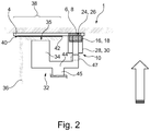
- the clamping system 1 having a clamping device 32 with a clamping body 34 and a clamping surface 35 and a contacting device electrically coupled with the clamping device 32 are shown in a lateral view.
- the clamping device 32 is shown in a very simplified manner and may be based on different working principles, which include manual, automated or automatable devices. A simple variant may be based on a toggle lever mechanism, in which a handle and lever arranged thereon may be brought into a first, clamping position or in a second, released position.
- the clamping body 34 is coupled with the contacting device 10 through a supporting arm 44, wherein the supporting arm 44 at the same time comprises a receptacle 45 for attaching to a robot or another guiding and holding device.
- a surface contact may be accomplished between the clamping body 34 and a second component 36.
- the second component 36 is positioned in a joining area 38 relative to the first component 2 through pressing the first clamping body 34 and thereby adjusts a predetermined gap 40.
- the compensation compound 42 is inserted and may be cured therein.
- the compensation compound 40 does not adhere in a material bond manner with the first component 2, such that the first component 2 can be separated from the second component 36 after curing the compensation compound 42 without any additional effort.
- the electrical contacting device 10 comes into contact with the contact zones 6 and 8, respectively, such that automatically with the clamping and positioning, respectively, of both components 2 and 36 relative to each other, also a transfer of an electrical current is accomplished.
- the contact surfaces 24, 26 are in contact with the contact zones 6, 8.
- the caps 16 and 18 are shifted relative to the guiding sleeves 28 and 30 against the springs 20 and 22 due to approaching of the clamping device 32 to the second component 36 and resultantly the electrical contacting device 10 to the separating foil 4, such that the contact surfaces 24 and 26 of the poles 12 and 14 are released.
- the caps 16 and 18 will, due to the spring action, be moved over the contacting surfaces 24 and 26 again.
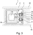
- Fig. 3 shows a top view onto the clamping system 1, in which the exemplarily mechanic coupling of the clamping device 32 and the electrical contacting device 10 are clearly visible.
- the supporting arm 44 is arranged between the first clamping body 34 and the two poles 6, 8 and carries them on a holding body 46.
- the supporting arm 44 and the holding body 46 exemplarily form a T-shaped compound.
- the receptacle 45 may be positioned on the supporting arm 44 in such a way, that the main force to be introduced is transferred onto the clamping body 34, while the holding body 46 is only exerted to a low force.
- the first component 2 may be clamped with a spatially fixated holding device 48, which is merely schematically indicated. This may suggest itself particularly when the first component 2 is particularly large-size and when the holding device 48 should particularly receive the own weight of the first component 2.
- the clamping device 32 is movable relative to the holding device 48 and it is sufficient to merely use a single clamping body 34 for pressing the second component 36. If it should be done without a holding device 48 fixated spatially it is necessary to use two clamping bodies on opposite sides of the component assembly.
- a spring device 47 which is shown in Figs. 2 and 3 with the dashed lines, may be arranged between the receptacle 45 and the poles 12 and 14 mechanically and serves for limiting the force acting on the holding body 46.
- the force acting from the contacting surfaces 24 and 26 onto the contact zones 6 and 8 resultantly is limited by such an embodiment and an inadvertent damaging of the separating foil 4 may be prevented.
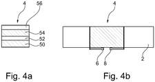
- separating foil 4 For clarification of the setup of the separating foil 4 it is schematically shown in Figs. 4a and 4b .
- an optional adhesive film 52 may be arranged, which carries a conductive heating layer 54, which is delimited by an anti-stick layer 56.
- the first component 2 may exemplarily be covered by the separating foil 4 partially, wherein two contact zones 6 and 8 are intended for providing an electrical contact.
Landscapes
- Engineering & Computer Science (AREA)
- Mechanical Engineering (AREA)
- Physics & Mathematics (AREA)
- Thermal Sciences (AREA)
- Lining Or Joining Of Plastics Or The Like (AREA)
- Electric Connection Of Electric Components To Printed Circuits (AREA)
- Chemical & Material Sciences (AREA)
- Chemical Kinetics & Catalysis (AREA)
- General Chemical & Material Sciences (AREA)
Claims (15)
- Spannsystem (1) zum Positionieren eines ersten Bauteils (2) und eines zweiten Bauteils (36) zueinander, aufweisend:- eine Spanneinrichtung (32),- eine Trennfolie (4) und- eine elektrische Kontakteinrichtung (10),wobei die Spanneinrichtung (32) dazu eingerichtet ist, in einer ersten Stellung das erste Bauteil (2) und das zweite Bauteil (36) in einer beabsichtigten Fügeposition unter Bildung eines Spalts zwischen den toleranzbehafteten Bauteilen (2, 36) zueinander zu fixieren und in einer zweiten Stellung die Fixierung zu lösen,
wobei die Trennfolie (4) eine Antihaftschicht (56) und eine mit elektrisch leitfähigen Kontaktzonen (6, 8) verbundene Heizschicht (54) zum Erwärmen einer in dem Spalt angebrachten aushärtbaren Ausgleichsmasse (42) aufweist,
wobei die elektrische Kontakteinrichtung (10) mechanisch mit der Spanneinrichtung (32) oder einer die Spanneinrichtung (32) haltenden Trageinrichtung gekoppelt ist und dazu eingerichtet ist, zumindest in der ersten Stellung der Spanneinrichtung (32) einen elektrischen Kontakt mit den Kontaktzonen (6, 8) herzustellen. - Spannsystem (1) nach Anspruch 1, wobei die Kontakteinrichtung (10) mindestens zwei voneinander beabstandete Pole (12, 14) aufweist, die durch Berühren der Kontaktzonen (6, 8) eine elektrische Verbindung mit der Heizschicht (54) herstellen.
- Spannsystem (1) nach Anspruch 2, wobei die Pole (12, 14) jeweils durch eine Kappe (16, 18) abdeckbar sind, wobei die jeweilige Kappe (16, 18) in der ersten Stellung zumindest jeweils eine Kontaktfläche (24, 26) des zugehörigen Pols (12, 14) zum Herstellen des elektrischen Kontakts freigibt.
- Spannsystem (1) nach Anspruch 3, wobei die Kappe (16, 18) hülsenartig ausgeformt ist und in einer zu der Kontaktfläche (24, 26) senkrechten Richtung an dem jeweiligen Pol (12, 14) bewegbar ist, wobei eine Feder (20, 22) die Kappe (16, 18) in einer über die Kontaktfläche (24, 26) ragenden und die Kontaktfläche (24, 26) vollständig abdeckenden Neutralstellung hält und durch Andrücken der Kappe (16, 18) auf eine damit korrespondierende Fläche in eine Öffnungsstellung bewegbar ist, so dass die Kontaktfläche (24, 26) auf der korrespondierenden Fläche aufliegt.
- Spannsystem (1) nach einem der vorhergehenden Ansprüche, wobei die Kontakteinrichtung (10) eine Federeinrichtung (47) aufweist, die zwischen den Polen (12, 14) und der Spanneinrichtung (32) oder der Trageinrichtung angeordnet ist und eine mechanische Verspannung der Pole (12, 14) mit den Kontaktzonen in der ersten Stellung verhindert.
- Spannsystem (1) nach einem der vorhergehenden Ansprüche, wobei die Spanneinrichtung (32) eine erste Spannfläche aufweist, die mit dem ersten Bauteil (2) oder dem zweiten Bauteil (36) in Flächenkontakt bringbar ist, wobei die Kontakteinrichtung (10) über mindestens einen Tragarm mit der ersten Spannfläche gekoppelt ist und wobei der mindestens eine Tragarm dazu eingerichtet ist, mit einer Trageinrichtung zum Halten der Spanneinrichtung (32) an der Trageinrichtung verbunden zu werden.
- Spannsystem (1) nach einem der vorhergehenden Ansprüche, wobei die Spanneinrichtung (32) mindestens einen Klemmkörper aufweist, der zum Fixieren auf eines des ersten Bauteils (2) und des zweiten Bauteils (36) aufdrückbar ist.
- Spannsystem (1) nach Anspruch 6 und 7, wobei sich der mindestens eine Tragarm quer zu der vorgesehenen Kraftrichtung des mindestens einen Klemmkörpers erstreckt und wobei die elektrische Kontakteinrichtung (10) mindestens zwei Pole (12, 14) aufweist, die an mindestens einem sich von dem mindestens einen Tragarm winklig und im Wesentlichen parallel zu der vorgesehenen Kraftrichtung erstreckenden Haltekörper angeordnet sind.
- Spannsystem (1) nach einem der vorhergehenden Ansprüche, ferner aufweisend eine Halteeinrichtung zum Einspannen eines des ersten Bauteils (2) oder des zweiten Bauteils (36), wobei die Spanneinrichtung (32) mit der Halteeinrichtung koppelbar ist, so dass in der ersten Stellung ein Fixieren des anderen des ersten Bauteils (2) oder des zweiten Bauteils (36) relativ zu dem an der Halteeinrichtung eingespannten ersten Bauteil (2) oder zweiten Bauteil (36) erfolgt.
- Spannsystem (1) nach Anspruch 9, wobei die Halteeinrichtung ein Roboter oder eine durch einen Roboter geführte Einrichtung ist.
- Spannsystem (1) nach Anspruch 2, wobei die Spanneinrichtung (32) zwei zueinander bewegbare Spannkörper aufweist, die das erste Bauteil (2) und das zweite Bauteil (36) in der Fügeposition zangenartig umgreifen und fixieren, wobei die Pole (12, 14) mindestens an einem der Spannkörper angeordnet sind.
- Verfahren zum Herstellen eines Maßausgleichs zwischen einem ersten Bauteil (2) und einem zweiten Bauteil (36), aufweisend die Schritte:- Anbringen einer Trennfolie auf einem des ersten Bauteils (2) und des zweiten Bauteils (36) in einer beabsichtigten Fügeposition, wobei die Trennfolie (4) eine Antihaftschicht (56) und eine mit elektrisch leitfähigen Kontaktzonen (6, 8) verbundene Heizschicht (54) zum Erwärmen einer in dem Spalt angebrachten aushärtbaren Ausgleichsmasse (42) aufweist,- Positionieren des ersten Bauteils (2) und des zweiten Bauteils (36) zueinander in einer beabsichtigten Fügeposition unter Bildung eines Spalts zwischen den toleranzbehafteten Bauteilen (2, 36),- Anbringen mindestens einer Spanneinrichtung (32) und Bringen in eine erste Stellung zum Fixieren des ersten Bauteils (2) und des zweiten Bauteils (36) zueinander, wobei eine mechanisch mit der mindestens einen Spanneinrichtung (32) gekoppelte elektrische Kontakteinrichtung (10) mit den Kontaktzonen (6, 8) der Trennfolie (4) eine elektrische Verbindung eingeht,- Einbringen einer aushärtbaren Ausgleichsmasse (42) in den Spalt,- Aushärten der Ausgleichsmasse (42) unter Erwärmung der Trennfolie (4) mit Hilfe der Heizschicht, die über die elektrische Kontakteinrichtung (10) mit Spannung versorgt wird,- Bringen der mindestens einen Spanneinrichtung (32) in eine zweite Stellung und Lösen der mindestens einen Spanneinrichtung (32), und- Entfernen der Trennfolie (4).
- Verfahren nach Anspruch 12,
wobei das Eingehen der elektrischen Verbindung das geführte Berühren oder mechanische Andrücken einer Kontaktfläche des jeweiligen Pols auf eine zugeordnete Kontaktzone umfasst. - Verfahren nach Anspruch 12 oder 13,
wobei das Positionieren des ersten Bauteils (2) und des zweiten Bauteils (36) zueinander das Einspannen eines des ersten Bauteils (2) und des zweiten Bauteils (36) in einer Halteeinrichtung umfasst und
wobei das Anbringen mindestens einer Spanneinrichtung (32) das Koppeln der mindestens einen Spanneinrichtung (32) mit der Halteeinrichtung umfasst, so dass in der ersten Stellung ein Fixieren des anderen des ersten Bauteils (2) oder des zweiten Bauteils (36) relativ zu dem an der Halteeinrichtung eingespannten ersten Bauteil (2) oder zweiten Bauteil (36) erfolgt. - Verfahren nach einem der Ansprüche 12 bis 14,
wobei nach dem Positionieren zwei zueinander bewegbare Spannkörper der mindestens einen Spanneinrichtung (32) das erste Bauteil (2) und das zweite Bauteil (36) in der Fügeposition zangenartig umgreifen und fixieren.
Applications Claiming Priority (1)
| Application Number | Priority Date | Filing Date | Title |
|---|---|---|---|
| DE102015114359.3A DE102015114359A1 (de) | 2015-08-28 | 2015-08-28 | Spannsystem zum Positionieren eines ersten Bauteils und eines zweiten Bauteils zueinander sowie Verfahren zum Herstellen eines Maßausgleichs zwischen zwei Bauteilen |
Publications (2)
| Publication Number | Publication Date |
|---|---|
| EP3135458A1 EP3135458A1 (de) | 2017-03-01 |
| EP3135458B1 true EP3135458B1 (de) | 2018-05-23 |
Family
ID=56852092
Family Applications (1)
| Application Number | Title | Priority Date | Filing Date |
|---|---|---|---|
| EP16185876.6A Not-in-force EP3135458B1 (de) | 2015-08-28 | 2016-08-26 | Klemmsystem zur positionierung einer ersten komponente und einer zweiten komponente in relativer lage zueinander sowie ein verfahren zur erzeugung eines dimensionalen ausgleichs zwischen den zwei komponenten |
Country Status (3)
| Country | Link |
|---|---|
| US (1) | US10207456B2 (de) |
| EP (1) | EP3135458B1 (de) |
| DE (1) | DE102015114359A1 (de) |
Families Citing this family (1)
| Publication number | Priority date | Publication date | Assignee | Title |
|---|---|---|---|---|
| GB2565081A (en) * | 2017-07-31 | 2019-02-06 | Airbus Operations Ltd | An assembly apparatus for forming an interfay joint during manufacture of an aircraft |
Family Cites Families (14)
| Publication number | Priority date | Publication date | Assignee | Title |
|---|---|---|---|---|
| US4923741A (en) | 1988-06-30 | 1990-05-08 | The United States Of America As Represented By The Administrator, National Aeronautics And Space Administration | Hazards protection for space suits and spacecraft |
| US5284002A (en) * | 1992-02-25 | 1994-02-08 | Simple Packaging Solutions, Inc. | Apparatus and method for making a reclosable storage bag |
| US5980665A (en) | 1996-05-31 | 1999-11-09 | The Boeing Company | Z-pin reinforced bonds for connecting composite structures |
| US5826503A (en) * | 1996-07-10 | 1998-10-27 | Harwil Corporation | Heat sealing apparatus for plastic bags |
| CA2316914C (en) | 1997-12-31 | 2008-06-10 | Textron Systems Corporation | Metallized sheeting, composites, and methods for their formation |
| US7682996B2 (en) | 2002-11-21 | 2010-03-23 | M-I L.L.C. | Vibratory screen |
| DE10319926B4 (de) | 2003-05-02 | 2006-09-28 | Airbus Deutschland Gmbh | Verfahren zum Ausgleichen eines Fügespaltes |
| US8329291B2 (en) | 2005-01-31 | 2012-12-11 | Timberline Tool, L.L.C. | Multi-layered composite system and method |
| US9109740B2 (en) | 2005-01-31 | 2015-08-18 | Timberline Tool, L.L.C. | Multi-layered patch system and method |
| DE102008044208A1 (de) | 2008-12-01 | 2010-06-10 | Airbus Deutschland Gmbh | Vorrichtung zum Aushärten eines Kunststoffmaterials |
| US8354624B2 (en) * | 2008-12-01 | 2013-01-15 | Airbus Operations Gmbh | Device for curing a plastic material |
| DE102009010437A1 (de) * | 2009-02-26 | 2010-09-02 | Tesa Se | Beheiztes Flächenelement |
| DE102010044116A1 (de) | 2010-10-05 | 2011-04-07 | Henkel Ag & Co. Kgaa | Verfahren zur Herstellung von Bauteilen |
| DE102013114574B4 (de) * | 2013-12-19 | 2016-11-03 | Airbus Operations Gmbh | Trennfolie sowie Verfahren |
-
2015
- 2015-08-28 DE DE102015114359.3A patent/DE102015114359A1/de not_active Withdrawn
-
2016
- 2016-08-26 US US15/248,225 patent/US10207456B2/en not_active Expired - Fee Related
- 2016-08-26 EP EP16185876.6A patent/EP3135458B1/de not_active Not-in-force
Non-Patent Citations (1)
| Title |
|---|
| None * |
Also Published As
| Publication number | Publication date |
|---|---|
| DE102015114359A1 (de) | 2017-03-02 |
| US20170057156A1 (en) | 2017-03-02 |
| EP3135458A1 (de) | 2017-03-01 |
| US10207456B2 (en) | 2019-02-19 |
Similar Documents
| Publication | Publication Date | Title |
|---|---|---|
| US20200171758A1 (en) | Composite rivet blank and installation thereof | |
| US10500736B2 (en) | Assembly tool, assembly device and assembly method | |
| DE102015107394B4 (de) | Effektor, Vorrichtung und Verfahren zum Aufnehmen, Handhaben und/oder Ablegen von textilen Strukturen | |
| CN102741122B (zh) | 用于将结构单元固定在飞机机身上的固定装置 | |
| US9452588B2 (en) | Adjustable shim | |
| CN107471655A (zh) | 用于制造应用于飞行器或航天器的结构部件的方法及装置 | |
| US9579713B2 (en) | Method for producing a vehicle body or a vehicle body module | |
| US20200055259A1 (en) | Heating element, device, and method for resistance welding of thermoplastic components, in particular for the production of aircraft, and aircraft | |
| US20160029437A1 (en) | Gripping apparatus | |
| US10207456B2 (en) | Clamping system for positioning a first component and a second component relative to each other as well as a method for producing a dimensional compensation between two components | |
| EP4223489B1 (de) | Elektrische isolationskomponente eines flugzeugs und verfahren zur herstellung einer elektrischen isolationskomponente | |
| EP3613567B1 (de) | Flexibler dorn zur herstellung von verbundstrukturen | |
| JP7004511B2 (ja) | 空洞内で材料を硬化するための方法及びシステム | |
| US10543670B2 (en) | Separating film and method | |
| CN107538765B (zh) | 用于柔性轨道的动态引导件 | |
| US10987877B2 (en) | Method for producing a vehicle component from a fiber-reinforced plastic | |
| CN109835462B (zh) | 飞行器接头、飞行器组件、安装工具及结构部件接合方法 | |
| CN106711845A (zh) | 绝缘操作杆和接线方法 | |
| EP4282627A1 (de) | Hitzeschild mit keramischer beschichtung zum induktionsschweissen | |
| US20230381883A1 (en) | Induction welding heat shield assembly with multiple heat shields with aligned recesses for induction welding path | |
| US20240181720A1 (en) | Pressure Tool, Pressing Apparatus And Method For Welding Plastics Components | |
| EP4309881B1 (de) | Schweissanordnung und -verfahren mit separat betätigbaren presskolben | |
| EP4721974A1 (de) | Verfahren zum verbinden einer leitfähigen schicht mit einem substrat | |
| GB2568764A (en) | Curable composite bush | |
| CN120133917A (zh) | 隔热垫抓取装置及具有其的装配系统 |
Legal Events
| Date | Code | Title | Description |
|---|---|---|---|
| PUAI | Public reference made under article 153(3) epc to a published international application that has entered the european phase |
Free format text: ORIGINAL CODE: 0009012 |
|
| STAA | Information on the status of an ep patent application or granted ep patent |
Free format text: STATUS: THE APPLICATION HAS BEEN PUBLISHED |
|
| AK | Designated contracting states |
Kind code of ref document: A1 Designated state(s): AL AT BE BG CH CY CZ DE DK EE ES FI FR GB GR HR HU IE IS IT LI LT LU LV MC MK MT NL NO PL PT RO RS SE SI SK SM TR |
|
| AX | Request for extension of the european patent |
Extension state: BA ME |
|
| STAA | Information on the status of an ep patent application or granted ep patent |
Free format text: STATUS: REQUEST FOR EXAMINATION WAS MADE |
|
| 17P | Request for examination filed |
Effective date: 20170703 |
|
| RBV | Designated contracting states (corrected) |
Designated state(s): AL AT BE BG CH CY CZ DE DK EE ES FI FR GB GR HR HU IE IS IT LI LT LU LV MC MK MT NL NO PL PT RO RS SE SI SK SM TR |
|
| GRAP | Despatch of communication of intention to grant a patent |
Free format text: ORIGINAL CODE: EPIDOSNIGR1 |
|
| STAA | Information on the status of an ep patent application or granted ep patent |
Free format text: STATUS: GRANT OF PATENT IS INTENDED |
|
| RIC1 | Information provided on ipc code assigned before grant |
Ipc: B29C 65/22 20060101ALI20171127BHEP Ipc: B29C 65/30 20060101ALI20171127BHEP Ipc: B29C 65/54 20060101ALN20171127BHEP Ipc: B29C 65/48 20060101ALN20171127BHEP Ipc: B29C 65/78 20060101AFI20171127BHEP |
|
| INTG | Intention to grant announced |
Effective date: 20171215 |
|
| GRAS | Grant fee paid |
Free format text: ORIGINAL CODE: EPIDOSNIGR3 |
|
| GRAA | (expected) grant |
Free format text: ORIGINAL CODE: 0009210 |
|
| STAA | Information on the status of an ep patent application or granted ep patent |
Free format text: STATUS: THE PATENT HAS BEEN GRANTED |
|
| AK | Designated contracting states |
Kind code of ref document: B1 Designated state(s): AL AT BE BG CH CY CZ DE DK EE ES FI FR GB GR HR HU IE IS IT LI LT LU LV MC MK MT NL NO PL PT RO RS SE SI SK SM TR |
|
| REG | Reference to a national code |
Ref country code: GB Ref legal event code: FG4D |
|
| REG | Reference to a national code |
Ref country code: CH Ref legal event code: EP |
|
| REG | Reference to a national code |
Ref country code: IE Ref legal event code: FG4D |
|
| REG | Reference to a national code |
Ref country code: AT Ref legal event code: REF Ref document number: 1001171 Country of ref document: AT Kind code of ref document: T Effective date: 20180615 |
|
| REG | Reference to a national code |
Ref country code: DE Ref legal event code: R096 Ref document number: 602016003190 Country of ref document: DE |
|
| REG | Reference to a national code |
Ref country code: FR Ref legal event code: PLFP Year of fee payment: 3 |
|
| REG | Reference to a national code |
Ref country code: NL Ref legal event code: MP Effective date: 20180523 |
|
| REG | Reference to a national code |
Ref country code: LT Ref legal event code: MG4D |
|
| PG25 | Lapsed in a contracting state [announced via postgrant information from national office to epo] |
Ref country code: SE Free format text: LAPSE BECAUSE OF FAILURE TO SUBMIT A TRANSLATION OF THE DESCRIPTION OR TO PAY THE FEE WITHIN THE PRESCRIBED TIME-LIMIT Effective date: 20180523 Ref country code: ES Free format text: LAPSE BECAUSE OF FAILURE TO SUBMIT A TRANSLATION OF THE DESCRIPTION OR TO PAY THE FEE WITHIN THE PRESCRIBED TIME-LIMIT Effective date: 20180523 Ref country code: LT Free format text: LAPSE BECAUSE OF FAILURE TO SUBMIT A TRANSLATION OF THE DESCRIPTION OR TO PAY THE FEE WITHIN THE PRESCRIBED TIME-LIMIT Effective date: 20180523 Ref country code: NO Free format text: LAPSE BECAUSE OF FAILURE TO SUBMIT A TRANSLATION OF THE DESCRIPTION OR TO PAY THE FEE WITHIN THE PRESCRIBED TIME-LIMIT Effective date: 20180823 Ref country code: BG Free format text: LAPSE BECAUSE OF FAILURE TO SUBMIT A TRANSLATION OF THE DESCRIPTION OR TO PAY THE FEE WITHIN THE PRESCRIBED TIME-LIMIT Effective date: 20180823 Ref country code: FI Free format text: LAPSE BECAUSE OF FAILURE TO SUBMIT A TRANSLATION OF THE DESCRIPTION OR TO PAY THE FEE WITHIN THE PRESCRIBED TIME-LIMIT Effective date: 20180523 |
|
| PG25 | Lapsed in a contracting state [announced via postgrant information from national office to epo] |
Ref country code: RS Free format text: LAPSE BECAUSE OF FAILURE TO SUBMIT A TRANSLATION OF THE DESCRIPTION OR TO PAY THE FEE WITHIN THE PRESCRIBED TIME-LIMIT Effective date: 20180523 Ref country code: HR Free format text: LAPSE BECAUSE OF FAILURE TO SUBMIT A TRANSLATION OF THE DESCRIPTION OR TO PAY THE FEE WITHIN THE PRESCRIBED TIME-LIMIT Effective date: 20180523 Ref country code: NL Free format text: LAPSE BECAUSE OF FAILURE TO SUBMIT A TRANSLATION OF THE DESCRIPTION OR TO PAY THE FEE WITHIN THE PRESCRIBED TIME-LIMIT Effective date: 20180523 Ref country code: LV Free format text: LAPSE BECAUSE OF FAILURE TO SUBMIT A TRANSLATION OF THE DESCRIPTION OR TO PAY THE FEE WITHIN THE PRESCRIBED TIME-LIMIT Effective date: 20180523 Ref country code: GR Free format text: LAPSE BECAUSE OF FAILURE TO SUBMIT A TRANSLATION OF THE DESCRIPTION OR TO PAY THE FEE WITHIN THE PRESCRIBED TIME-LIMIT Effective date: 20180824 |
|
| REG | Reference to a national code |
Ref country code: AT Ref legal event code: MK05 Ref document number: 1001171 Country of ref document: AT Kind code of ref document: T Effective date: 20180523 |
|
| PG25 | Lapsed in a contracting state [announced via postgrant information from national office to epo] |
Ref country code: DK Free format text: LAPSE BECAUSE OF FAILURE TO SUBMIT A TRANSLATION OF THE DESCRIPTION OR TO PAY THE FEE WITHIN THE PRESCRIBED TIME-LIMIT Effective date: 20180523 Ref country code: PL Free format text: LAPSE BECAUSE OF FAILURE TO SUBMIT A TRANSLATION OF THE DESCRIPTION OR TO PAY THE FEE WITHIN THE PRESCRIBED TIME-LIMIT Effective date: 20180523 Ref country code: SK Free format text: LAPSE BECAUSE OF FAILURE TO SUBMIT A TRANSLATION OF THE DESCRIPTION OR TO PAY THE FEE WITHIN THE PRESCRIBED TIME-LIMIT Effective date: 20180523 Ref country code: CZ Free format text: LAPSE BECAUSE OF FAILURE TO SUBMIT A TRANSLATION OF THE DESCRIPTION OR TO PAY THE FEE WITHIN THE PRESCRIBED TIME-LIMIT Effective date: 20180523 Ref country code: EE Free format text: LAPSE BECAUSE OF FAILURE TO SUBMIT A TRANSLATION OF THE DESCRIPTION OR TO PAY THE FEE WITHIN THE PRESCRIBED TIME-LIMIT Effective date: 20180523 Ref country code: AT Free format text: LAPSE BECAUSE OF FAILURE TO SUBMIT A TRANSLATION OF THE DESCRIPTION OR TO PAY THE FEE WITHIN THE PRESCRIBED TIME-LIMIT Effective date: 20180523 Ref country code: RO Free format text: LAPSE BECAUSE OF FAILURE TO SUBMIT A TRANSLATION OF THE DESCRIPTION OR TO PAY THE FEE WITHIN THE PRESCRIBED TIME-LIMIT Effective date: 20180523 |
|
| REG | Reference to a national code |
Ref country code: DE Ref legal event code: R097 Ref document number: 602016003190 Country of ref document: DE |
|
| PG25 | Lapsed in a contracting state [announced via postgrant information from national office to epo] |
Ref country code: IT Free format text: LAPSE BECAUSE OF FAILURE TO SUBMIT A TRANSLATION OF THE DESCRIPTION OR TO PAY THE FEE WITHIN THE PRESCRIBED TIME-LIMIT Effective date: 20180523 Ref country code: SM Free format text: LAPSE BECAUSE OF FAILURE TO SUBMIT A TRANSLATION OF THE DESCRIPTION OR TO PAY THE FEE WITHIN THE PRESCRIBED TIME-LIMIT Effective date: 20180523 |
|
| PG25 | Lapsed in a contracting state [announced via postgrant information from national office to epo] |
Ref country code: MC Free format text: LAPSE BECAUSE OF FAILURE TO SUBMIT A TRANSLATION OF THE DESCRIPTION OR TO PAY THE FEE WITHIN THE PRESCRIBED TIME-LIMIT Effective date: 20180523 |
|
| PLBE | No opposition filed within time limit |
Free format text: ORIGINAL CODE: 0009261 |
|
| STAA | Information on the status of an ep patent application or granted ep patent |
Free format text: STATUS: NO OPPOSITION FILED WITHIN TIME LIMIT |
|
| PG25 | Lapsed in a contracting state [announced via postgrant information from national office to epo] |
Ref country code: LU Free format text: LAPSE BECAUSE OF NON-PAYMENT OF DUE FEES Effective date: 20180826 |
|
| 26N | No opposition filed |
Effective date: 20190226 |
|
| REG | Reference to a national code |
Ref country code: BE Ref legal event code: MM Effective date: 20180831 |
|
| PG25 | Lapsed in a contracting state [announced via postgrant information from national office to epo] |
Ref country code: SI Free format text: LAPSE BECAUSE OF FAILURE TO SUBMIT A TRANSLATION OF THE DESCRIPTION OR TO PAY THE FEE WITHIN THE PRESCRIBED TIME-LIMIT Effective date: 20180523 |
|
| PG25 | Lapsed in a contracting state [announced via postgrant information from national office to epo] |
Ref country code: BE Free format text: LAPSE BECAUSE OF NON-PAYMENT OF DUE FEES Effective date: 20180831 |
|
| PGFP | Annual fee paid to national office [announced via postgrant information from national office to epo] |
Ref country code: DE Payment date: 20190822 Year of fee payment: 4 Ref country code: FR Payment date: 20190822 Year of fee payment: 4 |
|
| PG25 | Lapsed in a contracting state [announced via postgrant information from national office to epo] |
Ref country code: AL Free format text: LAPSE BECAUSE OF FAILURE TO SUBMIT A TRANSLATION OF THE DESCRIPTION OR TO PAY THE FEE WITHIN THE PRESCRIBED TIME-LIMIT Effective date: 20180523 |
|
| PG25 | Lapsed in a contracting state [announced via postgrant information from national office to epo] |
Ref country code: MT Free format text: LAPSE BECAUSE OF NON-PAYMENT OF DUE FEES Effective date: 20180826 |
|
| PG25 | Lapsed in a contracting state [announced via postgrant information from national office to epo] |
Ref country code: TR Free format text: LAPSE BECAUSE OF FAILURE TO SUBMIT A TRANSLATION OF THE DESCRIPTION OR TO PAY THE FEE WITHIN THE PRESCRIBED TIME-LIMIT Effective date: 20180523 |
|
| PG25 | Lapsed in a contracting state [announced via postgrant information from national office to epo] |
Ref country code: CH Free format text: LAPSE BECAUSE OF NON-PAYMENT OF DUE FEES Effective date: 20190831 Ref country code: LI Free format text: LAPSE BECAUSE OF NON-PAYMENT OF DUE FEES Effective date: 20190831 Ref country code: PT Free format text: LAPSE BECAUSE OF FAILURE TO SUBMIT A TRANSLATION OF THE DESCRIPTION OR TO PAY THE FEE WITHIN THE PRESCRIBED TIME-LIMIT Effective date: 20180523 |
|
| PG25 | Lapsed in a contracting state [announced via postgrant information from national office to epo] |
Ref country code: CY Free format text: LAPSE BECAUSE OF FAILURE TO SUBMIT A TRANSLATION OF THE DESCRIPTION OR TO PAY THE FEE WITHIN THE PRESCRIBED TIME-LIMIT Effective date: 20180523 Ref country code: HU Free format text: LAPSE BECAUSE OF FAILURE TO SUBMIT A TRANSLATION OF THE DESCRIPTION OR TO PAY THE FEE WITHIN THE PRESCRIBED TIME-LIMIT; INVALID AB INITIO Effective date: 20160826 Ref country code: MK Free format text: LAPSE BECAUSE OF NON-PAYMENT OF DUE FEES Effective date: 20180523 Ref country code: IE Free format text: LAPSE BECAUSE OF NON-PAYMENT OF DUE FEES Effective date: 20180826 |
|
| PG25 | Lapsed in a contracting state [announced via postgrant information from national office to epo] |
Ref country code: IS Free format text: LAPSE BECAUSE OF FAILURE TO SUBMIT A TRANSLATION OF THE DESCRIPTION OR TO PAY THE FEE WITHIN THE PRESCRIBED TIME-LIMIT Effective date: 20180923 |
|
| REG | Reference to a national code |
Ref country code: DE Ref legal event code: R119 Ref document number: 602016003190 Country of ref document: DE |
|
| GBPC | Gb: european patent ceased through non-payment of renewal fee |
Effective date: 20200826 |
|
| PG25 | Lapsed in a contracting state [announced via postgrant information from national office to epo] |
Ref country code: FR Free format text: LAPSE BECAUSE OF NON-PAYMENT OF DUE FEES Effective date: 20200831 Ref country code: DE Free format text: LAPSE BECAUSE OF NON-PAYMENT OF DUE FEES Effective date: 20210302 |
|
| PG25 | Lapsed in a contracting state [announced via postgrant information from national office to epo] |
Ref country code: GB Free format text: LAPSE BECAUSE OF NON-PAYMENT OF DUE FEES Effective date: 20200826 |