EP3134780B1 - Kompensation von roboterbewegungsabweichungen - Google Patents
Kompensation von roboterbewegungsabweichungen Download PDFInfo
- Publication number
- EP3134780B1 EP3134780B1 EP14721281.5A EP14721281A EP3134780B1 EP 3134780 B1 EP3134780 B1 EP 3134780B1 EP 14721281 A EP14721281 A EP 14721281A EP 3134780 B1 EP3134780 B1 EP 3134780B1
- Authority
- EP
- European Patent Office
- Prior art keywords
- drift
- motor
- robot
- value
- data
- Prior art date
- Legal status (The legal status is an assumption and is not a legal conclusion. Google has not performed a legal analysis and makes no representation as to the accuracy of the status listed.)
- Active
Links
Images
Classifications
-
- G—PHYSICS
- G05—CONTROLLING; REGULATING
- G05B—CONTROL OR REGULATING SYSTEMS IN GENERAL; FUNCTIONAL ELEMENTS OF SUCH SYSTEMS; MONITORING OR TESTING ARRANGEMENTS FOR SUCH SYSTEMS OR ELEMENTS
- G05B19/00—Programme-control systems
- G05B19/02—Programme-control systems electric
- G05B19/18—Numerical control [NC], i.e. automatically operating machines, in particular machine tools, e.g. in a manufacturing environment, so as to execute positioning, movement or co-ordinated operations by means of programme data in numerical form
- G05B19/404—Numerical control [NC], i.e. automatically operating machines, in particular machine tools, e.g. in a manufacturing environment, so as to execute positioning, movement or co-ordinated operations by means of programme data in numerical form characterised by control arrangements for compensation, e.g. for backlash, overshoot, tool offset, tool wear, temperature, machine construction errors, load, inertia
-
- B—PERFORMING OPERATIONS; TRANSPORTING
- B25—HAND TOOLS; PORTABLE POWER-DRIVEN TOOLS; MANIPULATORS
- B25J—MANIPULATORS; CHAMBERS PROVIDED WITH MANIPULATION DEVICES
- B25J9/00—Programme-controlled manipulators
- B25J9/10—Programme-controlled manipulators characterised by positioning means for manipulator elements
- B25J9/1005—Programme-controlled manipulators characterised by positioning means for manipulator elements comprising adjusting means
-
- B—PERFORMING OPERATIONS; TRANSPORTING
- B25—HAND TOOLS; PORTABLE POWER-DRIVEN TOOLS; MANIPULATORS
- B25J—MANIPULATORS; CHAMBERS PROVIDED WITH MANIPULATION DEVICES
- B25J9/00—Programme-controlled manipulators
- B25J9/16—Programme controls
- B25J9/1628—Programme controls characterised by the control loop
- B25J9/1641—Programme controls characterised by the control loop compensation for backlash, friction, compliance, elasticity in the joints
-
- G—PHYSICS
- G05—CONTROLLING; REGULATING
- G05B—CONTROL OR REGULATING SYSTEMS IN GENERAL; FUNCTIONAL ELEMENTS OF SUCH SYSTEMS; MONITORING OR TESTING ARRANGEMENTS FOR SUCH SYSTEMS OR ELEMENTS
- G05B2219/00—Program-control systems
- G05B2219/30—Nc systems
- G05B2219/37—Measurements
- G05B2219/37429—Temperature of motor
-
- G—PHYSICS
- G05—CONTROLLING; REGULATING
- G05B—CONTROL OR REGULATING SYSTEMS IN GENERAL; FUNCTIONAL ELEMENTS OF SUCH SYSTEMS; MONITORING OR TESTING ARRANGEMENTS FOR SUCH SYSTEMS OR ELEMENTS
- G05B2219/00—Program-control systems
- G05B2219/30—Nc systems
- G05B2219/41—Servomotor, servo controller till figures
- G05B2219/41127—Compensation for temperature variations of servo
-
- G—PHYSICS
- G05—CONTROLLING; REGULATING
- G05B—CONTROL OR REGULATING SYSTEMS IN GENERAL; FUNCTIONAL ELEMENTS OF SUCH SYSTEMS; MONITORING OR TESTING ARRANGEMENTS FOR SUCH SYSTEMS OR ELEMENTS
- G05B2219/00—Program-control systems
- G05B2219/30—Nc systems
- G05B2219/41—Servomotor, servo controller till figures
- G05B2219/41359—Gearbox
-
- G—PHYSICS
- G05—CONTROLLING; REGULATING
- G05B—CONTROL OR REGULATING SYSTEMS IN GENERAL; FUNCTIONAL ELEMENTS OF SUCH SYSTEMS; MONITORING OR TESTING ARRANGEMENTS FOR SUCH SYSTEMS OR ELEMENTS
- G05B2219/00—Program-control systems
- G05B2219/30—Nc systems
- G05B2219/49—Nc machine tool, till multiple
- G05B2219/49211—Compensation dilatation using calculated temperature from velocity
Definitions
- the present invention relates to the field of robots.
- the invention more particularly relates to a method, device, and computer program product for compensating robot movement deviations caused by a gear box as well as to a robot arrangement comprising such a device.
- a robot section such as a part of a robot arm is often controlled by a motor, such as a servo motor, together with a gear box.
- a motor such as a servo motor
- the control of industrial robots may in theory be so precise that the deviation from a desired position is very small. This allows the robot to perform fine and precise operations.
- the document US20090076653 discloses a system for estimating the gearbox temperature of an industrial robot in which temperature sensors are not necessary.
- the document JP2013154433 discloses a robot control system which takes into account the drift due to gearbox temperature variations.
- the present invention is therefore directed towards compensating robot movement deviations caused by a gear box connected between a robot section and a motor controlling the movement of the robot section.
- Another object of the present invention is to provide a device for compensating robot movement deviations caused by a gear box connected between a robot section and a motor controlling the movement of the robot section.
- the device may be a part of the robot controller for the robot.
- Another object of the present invention is to provide a robot arrangement comprising an industrial robot and a device for compensating robot movement deviations caused by a gear box.
- Another object of the present invention is to provide a computer program product for compensating robot movement deviations caused by a gear box connected between a robot section and a motor controlling the movement of the robot section.
- the present invention has many advantages. It allows a simple and fast compensation of the drift caused by temperature deviations in the gearbox. This improves the operation of the robot, which may perform more precise movements. Furthermore, this improvement can be achieved through program updates in the robot controller. Thereby the additional costs required for implementing the added functionality are low.
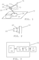
- Fig. 1 schematically shows a robot arrangement comprising a robot 10 and a robot controller 32.
- the robot 10 comprises a number of arm sections 12, 14 connected to each other via joints 16.
- the robot 10 shown in fig. 1 is simplified and therefore only two arm sections are shown, a first and a second arm section 12 and 14, connected to each other via joint 16. This means that in this example only one joint 16 which joins the first and second arm sections 12 and 14 is shown. It should however be realized that a robot normally comprises many more arm sections, typically six and consequently also several more joints that may be controlled.
- the first arm section 12 is here connected to a foundation 26.
- the robot 10 is attached to the foundation 26.
- the foundation may provide a first axis of rotation.
- this joint has been omitted from fig. 1 for the sake of clarity.
- the robot normally comprises a tool holder for allowing a tool 28 to be connected to the robot 10.
- Such a tool is typically connected to the outermost arm section of the robot, i.e. to the arm section furthest away from the foundation 26. Consequently, in fig. 1 one such tool 28 is shown as being attached to the second arm section 14.
- actuator 22 In order to move the second arm section 14 in relation to the first arm section 12 there is provided an actuator 22 at the joint 16, which actuator 22 may be implemented as a motor, for instance as a servo motor for moving the second arm around a second axis of rotation defined by the joint 16. Between this actuator and the joint 16 there is furthermore provided a gear box 20.
- a sensor connected to the joint.
- Such a sensor could be provided for sensing at least one property, such as a property of the robot, where variations in the property are being caused by the operation of the actuator 22.
- a property such as a property of the robot
- One possible property being sensed in this way is a position of the robot 10 and more specifically the position of the second arm section 14 in relation to the second axis.
- Another possible property is the speed of the motor 22.
- a further possible property is the acceleration of the motor.
- a further property is the torque of the second arm 14.
- a temperature sensor that senses the temperature of the location, i.e. the ambient temperature of the gearbox 20.
- the sensor may furthermore be placed or mounted on the actuator or the gear box.
- the joint 16, with actuator 22 and gear box 20 is also schematically shown in fig. 2 , which figure shows a perspective view of these elements.
- the robot controller 32 is connected to the robot 10 and more particularly to the actuator 22 and if there is a sensor also to this sensor.
- a block schematic of the robot controller 32 connected to the motor 22 is shown in fig. 3 .
- the robot controller 32 comprises a path planner unit PP 34 connected to a drift compensating unit DC 36.
- the drift compensating unit 36 is in turn connected to an arm control unit AC 38, which is finally connected to the motor M 22.
- the drift compensating unit 36 may also be considered to form a device for compensating robot movement deviations caused by a gear box.
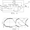
- Fig. 4 shows a process control schematic of the path planner unit 34, drift compensating unit 36, arm control unit 38, motor 22, gear box 20 and second arm 14.
- the path planner unit 34 provides motor data about the motor. In this case it provides motor data in the form of a desired motor position value q r , a desired motor velocity value q ⁇ r and a desired motor acceleration value q ⁇ r to a dynamic model block 40.
- the motor velocity value q ⁇ r is also provided to a drift estimating block 42 of the drift compensating unit 36, which drift estimating block 42 also receives a motor torque value ⁇ of the motor and a gravitation torque value ⁇ grav from the dynamic model block 40.
- the drift compensating unit 36 also comprises a drift adjusting block 44 connected between a signal output of the path planning unit 34 and a first signal input of a position control block 46 of the arm control unit 38.
- the drift adjusting block 44 receives a drift compensating value ⁇ q from the drift estimating block 42 and a position value qr from the path planning unit 34 and provides the sum of these to the first signal input of the position control block 46 of the arm control unit 38.
- the position control block 46 also has a signal output connected to a signal input of the torque control block 48, which has a signal output connected to the motor 22.
- the motor 22 in turn provides a motor position q in to the gear box 20, which controls the robot arm 14 with a positional value q out .
- the motor position q in is also provided in a feedback loop back to a second input of the position control block 46.
- the dynamic model block 40 comprises a dynamic model of the robot. Such a model may be used by the pattern planner unit 34. For this reason the dynamic model block 40 may as an alternative be a part of the path planner unit 34 instead of the drift compensating unit 36.
- This problem may be increased by the fact that the time constants of the thermal drift may be short ( ⁇ 2 min for increase of temperature, 4 minutes for decrease), and a short stop, e.g., will change tool position significantly. The drift may thus increase faster than it decreases. This problem is handled by the robot movement compensation system of the invention.
- the drift estimating block 42 estimates the drift, and outputs the adjustment ⁇ q .
- the drift estimating block 42 may employ a dynamic drift model to estimate the internal temperature of the gear box from speed q ⁇ r and torque ⁇ . It is not necessary to estimate the temperature as such, but only to obtain a measure of the temperature, which measure has the same behavior as the temperature variation. Knowing the temperature or measure, the drift can then be estimated based on the torque.
- the model used may be of a grey-box type and calibrated by measuring the drift using an external measurement system.
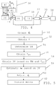
- fig. 5 shows a flow chart of a number of method steps in a method of compensating robot movement deviation being performed in the compensating unit 36.
- the path planning unit 34 determines a movement of the robot, for instance in order to move the robot along a robot path.
- the path is typically a path in which the tool 28 is to occupy a certain position at different instances of time.
- the path planner unit 34 provides a number of control commands for controlling motors to move corresponding arm sections, which movements together contribute to the desired tool movement.
- One of the motors being controlled is the motor 22 connected to the joint 16 via the gear box 20 for moving the second arm section 14.
- the path planning unit 34 provides a control value q r indicating a desired position of the second arm section 14, such as an angle in relation to the rotational axis defined by the joint 16. This is provided for use in controlling the movement of the second arm 14.
- the path planning unit 34 also provides a corresponding motor speed value q ⁇ r and acceleration value q ⁇ r , where all three values are provided as input to the dynamic model block 40 of the drift compensating unit 36 in order to obtain one or two torque values ⁇ and ⁇ grav of the second arm section 14 using the dynamic model of the robot.
- the values are here the total torque ⁇ of the motor 22 as well as the gravitational torque ⁇ grav of the motor. Both these torque values ⁇ and ⁇ grav and the motor speed value q ⁇ r are received by the drift estimating block 42 of the drift compensating unit 36.
- the drift estimating block 42 thus obtains motor data about the motor, here in the form of the motor speed q ⁇ r , step 50, as well as motor torque data, here in the form of the total motor torque ⁇ , step 52. Based on these two pieces of data it then determines a measure TM of the temperature of the gear box 20, step 54. After this has been done, the drift estimating block 42 obtains the gravitational torque value ⁇ grav from the dynamic model block 40, step 56, and thereafter determines a drift value DV based on the temperature measure TM and the gravitational torque ⁇ grav , step 58. The drift value is thus being obtained based on the gearbox temperature measure TM and the gravitational torque ⁇ grav of the motor.
- the drift estimating block 42 estimates a drift ⁇ q based on the drift value DV, step 59.
- the drift value DV is thereby used for obtaining an estimate of the drift ⁇ q .
- the drift value DV depends on the temperature measure TM and the gravitational torque ⁇ grav
- the estimated drift ⁇ q depends on the temperature measure TM and the gravitational torque ⁇ grav .
- the drift value DV is used as the estimated drift ⁇ q .
- the estimated drift ⁇ q is then provided to the drift adjusting block 44 for being subtracted from the control value q r, and in this way the drift adjusting block 44 adjusts the control value q r , step 60. It thus adjusts the control value qr that is used to control the positioning of the robot based on the estimated drift. This estimated drift ⁇ q thus compensates for the drift in the gear box output signal q out .
- the adjusted control value is then provided to the position control block 46 of the arm control unit 38, which after further processing delivers a process control signal to the torque control block 48, which in turn further processes the signal for providing as a control command to the motor 22, step 62.
- the motor 22 then controls the position of the arm section 14 with a position q in , which is translated by the gear box 20 to a position q out for controlling the arm section 14.
- the motor position q in is also fed back to the position control block 46 in a feedback control loop.
- the adjustment is a feed forward adjustment, which provides a fast compensation of the drift.
- Fig. 6 shows a block schematic of one realization of the drift estimating block 42. It comprises a first signal processing branch comprising an optional absolute value forming element AV 64 with an input that receives the motor speed q ⁇ r .
- the absolute value forming element AV 64 also has an output that is connected to a first input of a temperature dependent measure forming element.
- the temperature dependent measure forming element may be a dynamic model of grey box - black box type that uses motor speed and optionally also motor torque to determine or estimate a measure of the gear box temperature.
- the temperature dependent measure forming element is in the form of a low pass filter LP 66, which in turn has an output connected to the input of a temperature measure handling element 68.
- the second signal processing branch comprises a sign determining element 70 having an input that also receives the motor speed q ⁇ r .
- the sign determining element 70 is connected to a multiplying element 72, which is also connected to an output of the temperature measure handling element 68 and thereby it interconnects the first and second signal processing branches.
- TM a measure of the temperature based on the speed q ⁇ r and the motor torque ⁇ .
- This measure TM may be determined using the low pass filter 66. It is here possible that the motor speed q ⁇ r is directly used as an input signal to the low pass filter 66. However, in the example given in fig. 6 the motor speed is supplied to the absolute value forming element 64, which determines the absolute value
- the filter coefficients may be set based on the change of the motor speed values being input.
- these coefficients may be set in the following way:
- the output TM at time t may be determined from the input, i.e. (absolute) speed, at time t and the output at a previous time (t-1), where t-1 and t are two consecutive sampling times.
- the filter characteristics i.e. the coefficients coeff1 and coeff2 for heating and cooling may be set according to the time evolution of a pre-measured drift value for a specific gravity torque.
- the result of this filtering is the temperature measure TM, which is supplied to the temperature measure handling element 68.
- the temperature measure handling element 68 applies the temperature measure TM and gravitational torque ⁇ grav on known relationships between drift value DV, temperature measure TM and gravitational torque ⁇ grav in order to obtain a drift value.
- the temperature measure handling element 68 may comprise pre-measured drift values, which drift values have been measured for different known combinations of gravitational torque and temperature measure TM.
- the pre-measured drift values may be provided in the form of curves or equations outlining the dependency between the drift value DV and gravitational torque ⁇ grav .
- a curve or an equation may set out the dependency of gravitational torque ⁇ grav and drift value DV for a specific temperature measure TM.
- the pre-measured drift values may as an alternative be provided in the form of one or more tables.
- a table may comprise drift values depending on different temperature measure TM and gravitational torque values.
- a drift value may then be a table entry that is identified by the corresponding temperature measure and gravitational torque values in the columns and rows of the table.
- of the speed may be used for compensating the drift. This can be used to obtain a drift value that is independent of the direction of movement.
- the second signal processing branch it is possible to use the second signal processing branch.
- the motor speed q ⁇ r is provided to the sign determining element 70, which determines the sign of the speed q ⁇ r. This sign, which is thus a positive or a negative value, is then provided to the multiplying element 72 where it is multiplied with the drift value DV obtained from the temperature measure handling element 68. Thereby the sign of the speed q ⁇ r is multiplied with the drift value DV and the product is provided as the estimated drift ⁇ q .
- two drift estimating blocks 42 are connected in parallel, where one is provided with the second signal processing branch and the other lacks such a branch, where the output of these block are added to each other in order to obtain a total compensation that comprises both movement direction dependent and movement direction independent drift compensating components.
- the other drift estimating block thus lack sign determining element and there is an adding unit for adding the drift values obtained from the two drift estimating blocks to each other in order to obtain the estimated drift.
- drift components that are better modelled as a translation of the gearbox, or a rotation in other directions than the output direction, these components could be compensated for in the same way as described here.
- the difference is that, e.g. a translational drift, must be compensated by more than one joint position. This means that kinematics may have to be used to translate drift to motor position compensation.
- the torques may be estimated through the use of a dynamic model of the robot.
- This model maybe a rigid body dynamic model of the robot where all position, speed and acceleration dependent torques for a rigid robot are determined based on information about position, speed and acceleration.
- the position dependent torque is gravity and the sum of all torques is the total torque.
- drift compensating unit may be considered to form a device for compensating robot movement deviations caused by a gear box, it is clear that the dynamics model block may be omitted from the device.
- the drift compensating unit is such a device.
- one or more of the other units of the robot controller may be included in the device for compensating robot movement deviations caused by the gear box. It is for instance possible that the whole robot controller is considered to be such a device.
- the different units of the robot controller and thus also the drift compensating unit 36 may be provided in the form of one or more processors together with computer program memory including computer program code for performing the functions of these units. As an alternative they may be provided in the form of one or more Application Specific Integrated Circuits (ASIC) or Field-Programmable Gate Arrays (FPGA).
- ASIC Application Specific Integrated Circuit
- FPGA Field-Programmable Gate Arrays
- This computer program code may also be provided on one or more data carriers which perform the functionality of the robot controller and especially of the drift compensating unit when the program code thereon is being loaded in a computer forming the robot controller.
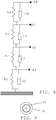
- One such data carrier 78 with computer program code 80, in the form of a CD ROM disc, is schematically shown in fig. 9 .
- Such computer program may as an alternative be provided on a server and downloaded therefrom into the computer forming the parameter determining device.
Landscapes
- Engineering & Computer Science (AREA)
- Robotics (AREA)
- Mechanical Engineering (AREA)
- Human Computer Interaction (AREA)
- Manufacturing & Machinery (AREA)
- Physics & Mathematics (AREA)
- General Physics & Mathematics (AREA)
- Automation & Control Theory (AREA)
- Manipulator (AREA)
- Control Of Electric Motors In General (AREA)
Claims (13)
- Verfahren zum Kompensieren von Roboterbewegungsabweichungen, die durch ein Getriebe (20) verursacht werden, das zwischen einem Roboterabschnitt (14) und einem Motor (22) eingebaut ist, das die Bewegung des Roboterabschnitts (14) steuert, wobei das Verfahren die folgenden Schritte umfasst:- Erhalten (50) von Motordaten (q̇r) des Motors (22) ;- Erhalten (52) von Motordrehmomentdaten (τ);- Bestimmen (54) einer Maßzahl (TM) der Temperatur des Getriebes (20) auf der Basis der Motordaten (q̇r) und der Motordrehmomentdaten (τ);- Abschätzen (59) der Drift (Δq) auf der Basis eines Driftwerts (DV) des Roboterabschnitts, wobei der Driftwert wiederum auf der Basis des Getriebetemperaturmesswerts (TM) und eines gravitationsbedingten Drehmoments (τgrav) des Motors erhalten wird (58), wobei der Driftwert oder der Driftwert nach einer Verarbeitung als die abgeschätzte Drift verwendet wird; und- Einstellen (60) eines Steuerungswerts (qr), der zum Steuern der Positionierung des Roboters auf der Basis der abgeschätzten Drift (Δq) verwendet wird;wobei die Abschätzung der Drift das Erhalten des Driftwerts (DV) durch Anwenden des Temperaturmesswerts und des gravitationsbedingten Drehmoments bei bekannten Beziehungen zwischen Driftwert, Temperaturmesswert und gravitationsbedingtem Drehmoment umfasst und das Bestimmen des Temperaturmesswerts eine Tiefpassfilterung der Motordaten umfasst, wobei das Ergebnis der Filterung der Temperaturmesswert ist.
- Verfahren nach Anspruch 1, wobei die Tiefpassfilterung eine Tiefpassfilterung des Absolutwerts der Motordaten umfasst.
- Verfahren nach Anspruch 2, das ferner das Bestimmen des Vorzeichens der Motordaten und das Multiplizieren des Driftwerts mit dem Vorzeichen der Motordaten umfasst, um die abgeschätzte Drift zu erhalten.
- Verfahren nach Anspruch 1 oder 2, wobei der Driftwert die abgeschätzte Drift ist.
- Verfahren nach einem der vorhergehenden Ansprüche, wobei die Motordaten die Geschwindigkeit der Motorbewegung umfassen.
- Verfahren nach einem der vorhergehenden Ansprüche, wobei die Motordaten eine Motorposition umfassen und wobei das gravitationsbedingte Drehmoment erhalten wird, indem die Motorposition in einem dynamischen Modell des Roboters verwendet wird.
- Vorrichtung (36) zum Kompensieren von Roboterbewegungsabweichungen, die durch ein Getriebe (20) verursacht werden, das zwischen einem Roboterabschnitt (14) und einem Motor (22) eingebaut ist, das die Bewegung des Roboterabschnitts (14) steuert, wobei die Vorrichtung Folgendes umfasst:wenigstens einen Block (42) zum Abschätzen der Drift, der konfiguriert ist, die folgenden Schritte auszuführen:- Erhalten von Motordaten (q̇r) des Motors (22);- Erhalten von Motordrehmomentdaten (τ);- Bestimmen einer Maßzahl (TM) der Temperatur des Getriebes (20) auf der Basis der Motordaten (q̇r) und der Motordrehmomentdaten (τ); und- Abschätzen der Drift (Δq) auf der Basis eines Driftwerts (DV) des Roboterabschnitts, wobei der Driftwert wiederum auf der Basis des Getriebetemperaturmesswerts (TM) und eines gravitationsbedingten Drehmoments (τgrav) des Motors erhalten wird, wobei der Driftwert oder der Driftwert nach einer Verarbeitung als die abgeschätzte Drift verwendet wird; undeinen Block (44) zum Einstellen einer Drift, der konfiguriert ist, einen Steuerungswert, der zum Steuern der Positionierung des Roboters auf der Basis der abgeschätzten Drift (Δq) verwendet wird, einzustellen,wobei der Block (42) zum Abschätzen einer Drift ein Bedienelement (68) zur Temperaturmessung, das konfiguriert ist, den Driftwert (DV) durch Anwenden des Temperaturmesswerts und des gravitationsbedingten Drehmoments bei bekannten Beziehungen zwischen Driftwert, Temperaturmesswert und gravitationsbedingtem Drehmoment zu erhalten, und ein Element (66) zum Bilden eines temperaturabhängigen Messwerts, das konfiguriert ist, den Messwert durch Tiefpassfilterung der Motordaten zu bestimmen, wobei das Ergebnis der Filterung der Temperaturmesswert ist, umfasst.
- Vorrichtung nach Anspruch 7, wobei der Block (42) zum Abschätzen einer Drift ein Element (64) zum Bilden eines Absolutwerts, das mit dem Element (66) zum Bilden eines temperaturabhängigen Messwerts verbunden ist, umfasst, damit das Element (66) zum Bilden eines temperaturabhängigen Messwerts den Absolutwert der Motordaten einer Tiefpassfilterung unterzieht.
- Vorrichtung nach Anspruch 8, wobei der Block (42) zum Abschätzen einer Drift ferner ein Element 70 zum Bestimmen des Vorzeichens, das konfiguriert ist, das Vorzeichen der Motordaten zu bestimmen, und ein Multiplikationselement (72), das konfiguriert ist, den Driftwert mit dem Vorzeichen der Motordaten zu multiplizieren, umfasst, um die abgeschätzte Drift zu erhalten.
- Vorrichtung nach Anspruch 9, wobei es einen weiteren Block zum Abschätzen einer Drift ohne Element zum Bestimmen des Vorzeichens und eine Additionseinheit zum Addieren der Driftwerte von den zwei Blöcken zum Abschätzen einer Drift gibt, um die abgeschätzte Drift zu erhalten.
- Vorrichtung nach einem der Ansprüche 7-10, wobei die Motordaten eine Motorposition umfassen und wobei die Vorrichtung ferner einen Block (40) eines dynamischen Modells umfasst, der konfiguriert ist, das gravitationsbedingte Drehmoment durch Nutzung der Motorposition in einem dynamischen Modell des Roboters zu erhalten.
- Roboteranordnung, die einen Industrieroboter und eine Vorrichtung (36) zum Kompensieren von Roboterbewegungsabweichungen umfasst,
wobei der Industrieroboter (10) ferner Folgendes umfasst:eine Anzahl von beweglichen Armabschnitten (12, 14),wenigstens einen Motor (20) zum Bewegen eines entsprechenden Armabschnitts, undein Getriebe (22) zwischen dem Motor und dem Armabschnitt,wobei die Vorrichtung (36) zum Kompensieren von Roboterbewegungsabweichungen Folgendes umfasst:
einen Block (42) zum Abschätzen einer Drift und einen Block (44) zum Einstellen einer Drift nach einem der Ansprüche 7-11. - Computerprogrammprodukt zum Kompensieren von Roboterbewegungsabweichungen, die durch ein Getriebe (20) verursacht werden, das zwischen einem Roboterabschnitt (14) und einem Motor (22) eingebaut ist, das die Bewegung des Roboterabschnitts (14) steuert, wobei das Computerprogrammprodukt einen Datenträger (78) mit Computerprogrammcode (80) umfasst, der dann, wenn er in einer Vorrichtung (36) zum Kompensieren von Roboterbewegungsabweichungen läuft, bewirkt, dass die Vorrichtung die folgenden Schritte ausführt:- Erhalten von Motordaten (q̇r) des Motors (22);- Erhalten von Motordrehmomentdaten (τ);- Bestimmen einer Maßzahl (TM) der Temperatur des Getriebes (20) auf der Basis der Motordaten (q̇r) und der Motordrehmomentdaten (τ);- Abschätzen der Drift (Δq) auf der Basis eines Driftwerts (DV) des Roboterabschnitts, wobei der Driftwert wiederum auf der Basis des Getriebetemperaturmesswerts (TM) und eines gravitationsbedingten Drehmoments (τgrav) des Motors erhalten wird, wobei der Driftwert oder der Driftwert nach einer Verarbeitung als die abgeschätzte Drift verwendet wird; und- Einstellen eines Steuerungswerts (qr), der zum Steuern der Positionierung des Roboters auf der Basis der abgeschätzten Drift (Δq) verwendet wird, wobei das Abschätzen der Drift das Erhalten des Driftwerts (DV) durch Anwenden des Temperaturmesswerts und des gravitationsbedingten Drehmoments bei bekannten Beziehungen zwischen Driftwert, Temperaturmesswert und gravitationsbedingtem Drehmoment umfasst und das Bestimmen des Temperaturmesswerts eine Tiefpassfilterung der Motordaten umfasst, wobei das Ergebnis der Filterung der Temperaturmesswert ist.
Applications Claiming Priority (1)
| Application Number | Priority Date | Filing Date | Title |
|---|---|---|---|
| PCT/EP2014/058097 WO2015161864A1 (en) | 2014-04-22 | 2014-04-22 | Compensating robot movement deviations |
Publications (2)
| Publication Number | Publication Date |
|---|---|
| EP3134780A1 EP3134780A1 (de) | 2017-03-01 |
| EP3134780B1 true EP3134780B1 (de) | 2019-11-20 |
Family
ID=50639464
Family Applications (1)
| Application Number | Title | Priority Date | Filing Date |
|---|---|---|---|
| EP14721281.5A Active EP3134780B1 (de) | 2014-04-22 | 2014-04-22 | Kompensation von roboterbewegungsabweichungen |
Country Status (4)
| Country | Link |
|---|---|
| US (1) | US10331107B2 (de) |
| EP (1) | EP3134780B1 (de) |
| CN (1) | CN106233214B (de) |
| WO (1) | WO2015161864A1 (de) |
Families Citing this family (11)
| Publication number | Priority date | Publication date | Assignee | Title |
|---|---|---|---|---|
| US10603794B2 (en) * | 2015-08-27 | 2020-03-31 | Accel Robotics Corporation | Robotic camera system |
| US9975244B1 (en) * | 2016-08-02 | 2018-05-22 | X Development Llc | Real-time generation of trajectories for actuators of a robot |
| CN109773827B (zh) * | 2017-11-10 | 2021-12-07 | 上银科技股份有限公司 | 用于机械臂的负载估测重力补偿的方法及其系统 |
| CN111819037B (zh) | 2018-02-26 | 2023-06-02 | 三菱电机株式会社 | 校正函数生成装置、机器人控制系统及机器人系统 |
| WO2019238975A1 (en) * | 2018-06-15 | 2019-12-19 | Universal Robots A/S | Dual mode free-drive of robot arm |
| JP7199178B2 (ja) * | 2018-08-28 | 2023-01-05 | 株式会社東芝 | ロボット制御装置、ロボット装置、ロボット制御のパラメータ調整方法、およびプログラム |
| EP3623113A1 (de) | 2018-09-14 | 2020-03-18 | Universal Robots A/S | Erhalten der getriebesteifigkeit eines robotergelenkgetriebes eines roboterarms |
| WO2020185440A1 (en) * | 2019-03-08 | 2020-09-17 | Covidien Lp | Methods for analog temperature compensation of bias and offsets of a differential sensor |
| WO2020211914A1 (en) | 2019-04-17 | 2020-10-22 | Universal Robots A/S | Method of controlling a robot arm based on adaptive friction |
| LU102199B1 (de) * | 2020-11-10 | 2022-05-10 | Nabtesco Prec Europe Gmbh | Verfahren und Steuerungsvorrichtung zum Steuern einer Bewegung eines mehrachsigen Roboters |
| CN119598821B (zh) * | 2025-02-12 | 2025-04-29 | 西北工业大学 | 一种花键键齿的螺旋角修形调整方法 |
Family Cites Families (15)
| Publication number | Priority date | Publication date | Assignee | Title |
|---|---|---|---|---|
| KR0160997B1 (ko) | 1992-09-18 | 1998-12-15 | 윤종용 | 로보트위치제어장치에서의 써보의 웜업드리프트 보상방법 |
| DE19848642A1 (de) | 1998-10-22 | 2000-04-27 | Heidenhain Gmbh Dr Johannes | Verfahren zur Kompensation von temperaturbedingten Maßabweichungen in der Maschinengeometrie |
| SE0104320D0 (sv) * | 2001-12-19 | 2001-12-19 | Abb Ab | Metod vid industrirobotsystem |
| KR100486505B1 (ko) * | 2002-12-31 | 2005-04-29 | 엘지전자 주식회사 | 로봇 청소기의 자이로 오프셋 보정방법 |
| SE0301531L (sv) * | 2003-05-22 | 2004-11-23 | Abb Ab | A Control method for a robot |
| DE102004056861A1 (de) * | 2004-11-25 | 2006-06-08 | Kuka Roboter Gmbh | Verfahren und Vorrichtung zum Regeln, Steuern von Manipulatoren |
| JP4650062B2 (ja) | 2005-03-31 | 2011-03-16 | 株式会社安川電機 | ロボット制御装置およびロボットの位置決め精度補正方法 |
| US20100032242A1 (en) * | 2008-08-05 | 2010-02-11 | Lin Chung-Chuan | Pressure Relief Device for a Gear Box |
| DE102008060052A1 (de) | 2008-12-02 | 2010-06-17 | Kuka Roboter Gmbh | Verfahren und Vorrichtung zur Kompensation einer kinematischen Abweichung |
| CN101774065B (zh) * | 2010-03-17 | 2012-09-12 | 昆山工研院工业机器人研究所有限公司 | 机器人焊缝跟踪偏差补偿方法 |
| DE102011003506A1 (de) * | 2011-02-02 | 2012-08-16 | Kuka Roboter Gmbh | Industrieroboter |
| DE102011012809A1 (de) * | 2011-03-02 | 2012-09-06 | Dürr Systems GmbH | Robotergetriebe mit einer Druckausgleichseinrichtung |
| JP2013154433A (ja) * | 2012-01-30 | 2013-08-15 | Canon Inc | ロボット |
| CN102806560B (zh) * | 2012-08-24 | 2014-08-06 | 电子科技大学 | 一种可自动消除机器人运动累积误差的方法 |
| CN202994132U (zh) * | 2012-12-19 | 2013-06-12 | 华南理工大学 | 一种直角坐标方式的机器人位姿误差测量系统 |
-
2014
- 2014-04-22 EP EP14721281.5A patent/EP3134780B1/de active Active
- 2014-04-22 WO PCT/EP2014/058097 patent/WO2015161864A1/en not_active Ceased
- 2014-04-22 US US15/301,553 patent/US10331107B2/en active Active
- 2014-04-22 CN CN201480078126.9A patent/CN106233214B/zh active Active
Non-Patent Citations (1)
| Title |
|---|
| None * |
Also Published As
| Publication number | Publication date |
|---|---|
| CN106233214B (zh) | 2019-04-12 |
| US10331107B2 (en) | 2019-06-25 |
| EP3134780A1 (de) | 2017-03-01 |
| US20170108848A1 (en) | 2017-04-20 |
| CN106233214A (zh) | 2016-12-14 |
| WO2015161864A1 (en) | 2015-10-29 |
Similar Documents
| Publication | Publication Date | Title |
|---|---|---|
| EP3134780B1 (de) | Kompensation von roboterbewegungsabweichungen | |
| CN105900027B (zh) | 轨迹控制装置 | |
| TWI435517B (zh) | Load inertia estimation method and control parameter adjustment method | |
| JP6238421B2 (ja) | 関節の少なくとも1つの特性を求める方法およびシステム | |
| US8896255B2 (en) | Servo controller having function for correcting amount of expansion/contraction of ball screw | |
| KR101522511B1 (ko) | 제어 방법 및 제어 장치 | |
| JP6214948B2 (ja) | 摩擦補償装置及び摩擦補償方法並びにサーボ制御装置 | |
| CN101062561B (zh) | 机器人操作参数调整方法和装置 | |
| CN107111296A (zh) | 用于补偿工作点的偏差的方法 | |
| WO2014167808A1 (ja) | モータ駆動装置 | |
| KR102114068B1 (ko) | 계산 토크 방식 제어기, 이의 파라미터 결정 및 성능 평가 방법 | |
| CN104115083B (zh) | 伺服控制装置 | |
| Wei et al. | A fast dynamic pose estimation method for vision-based trajectory tracking control of industrial robots | |
| Hua et al. | Visual tracking control for an uncalibrated robot system with unknown camera parameters | |
| CN109388099B (zh) | 利用模型支持的误差补偿对工件的加工 | |
| JP7068133B2 (ja) | 制御システム、制御方法、及び制御プログラム | |
| CN110035867B (zh) | 数控装置 | |
| Andres Lara-Molina et al. | Robust generalized predictive control of the orthoglide robot | |
| Marton et al. | Control of robotic systems with unknown friction and payload | |
| JP4650062B2 (ja) | ロボット制御装置およびロボットの位置決め精度補正方法 | |
| JP4483314B2 (ja) | サーボ制御装置 | |
| Fujisaki et al. | Motion-copying system with in-tool sensing | |
| CN109143968B (zh) | 控制装置、位置控制系统、位置控制方法及记录媒体 | |
| JP2019219762A (ja) | 制御装置、制御方法及びプログラム | |
| Cheung et al. | Robust learning control of a high precision planar parallel manipulator |
Legal Events
| Date | Code | Title | Description |
|---|---|---|---|
| STAA | Information on the status of an ep patent application or granted ep patent |
Free format text: STATUS: THE INTERNATIONAL PUBLICATION HAS BEEN MADE |
|
| PUAI | Public reference made under article 153(3) epc to a published international application that has entered the european phase |
Free format text: ORIGINAL CODE: 0009012 |
|
| STAA | Information on the status of an ep patent application or granted ep patent |
Free format text: STATUS: REQUEST FOR EXAMINATION WAS MADE |
|
| 17P | Request for examination filed |
Effective date: 20161122 |
|
| AK | Designated contracting states |
Kind code of ref document: A1 Designated state(s): AL AT BE BG CH CY CZ DE DK EE ES FI FR GB GR HR HU IE IS IT LI LT LU LV MC MK MT NL NO PL PT RO RS SE SI SK SM TR |
|
| AX | Request for extension of the european patent |
Extension state: BA ME |
|
| DAX | Request for extension of the european patent (deleted) | ||
| GRAP | Despatch of communication of intention to grant a patent |
Free format text: ORIGINAL CODE: EPIDOSNIGR1 |
|
| STAA | Information on the status of an ep patent application or granted ep patent |
Free format text: STATUS: GRANT OF PATENT IS INTENDED |
|
| INTG | Intention to grant announced |
Effective date: 20190703 |
|
| GRAS | Grant fee paid |
Free format text: ORIGINAL CODE: EPIDOSNIGR3 |
|
| GRAA | (expected) grant |
Free format text: ORIGINAL CODE: 0009210 |
|
| STAA | Information on the status of an ep patent application or granted ep patent |
Free format text: STATUS: THE PATENT HAS BEEN GRANTED |
|
| AK | Designated contracting states |
Kind code of ref document: B1 Designated state(s): AL AT BE BG CH CY CZ DE DK EE ES FI FR GB GR HR HU IE IS IT LI LT LU LV MC MK MT NL NO PL PT RO RS SE SI SK SM TR |
|
| REG | Reference to a national code |
Ref country code: GB Ref legal event code: FG4D |
|
| REG | Reference to a national code |
Ref country code: CH Ref legal event code: EP |
|
| REG | Reference to a national code |
Ref country code: IE Ref legal event code: FG4D |
|
| REG | Reference to a national code |
Ref country code: DE Ref legal event code: R096 Ref document number: 602014057058 Country of ref document: DE |
|
| REG | Reference to a national code |
Ref country code: AT Ref legal event code: REF Ref document number: 1204877 Country of ref document: AT Kind code of ref document: T Effective date: 20191215 |
|
| REG | Reference to a national code |
Ref country code: NL Ref legal event code: MP Effective date: 20191120 |
|
| REG | Reference to a national code |
Ref country code: LT Ref legal event code: MG4D |
|
| PG25 | Lapsed in a contracting state [announced via postgrant information from national office to epo] |
Ref country code: FI Free format text: LAPSE BECAUSE OF FAILURE TO SUBMIT A TRANSLATION OF THE DESCRIPTION OR TO PAY THE FEE WITHIN THE PRESCRIBED TIME-LIMIT Effective date: 20191120 Ref country code: BG Free format text: LAPSE BECAUSE OF FAILURE TO SUBMIT A TRANSLATION OF THE DESCRIPTION OR TO PAY THE FEE WITHIN THE PRESCRIBED TIME-LIMIT Effective date: 20200220 Ref country code: LT Free format text: LAPSE BECAUSE OF FAILURE TO SUBMIT A TRANSLATION OF THE DESCRIPTION OR TO PAY THE FEE WITHIN THE PRESCRIBED TIME-LIMIT Effective date: 20191120 Ref country code: NL Free format text: LAPSE BECAUSE OF FAILURE TO SUBMIT A TRANSLATION OF THE DESCRIPTION OR TO PAY THE FEE WITHIN THE PRESCRIBED TIME-LIMIT Effective date: 20191120 Ref country code: NO Free format text: LAPSE BECAUSE OF FAILURE TO SUBMIT A TRANSLATION OF THE DESCRIPTION OR TO PAY THE FEE WITHIN THE PRESCRIBED TIME-LIMIT Effective date: 20200220 Ref country code: LV Free format text: LAPSE BECAUSE OF FAILURE TO SUBMIT A TRANSLATION OF THE DESCRIPTION OR TO PAY THE FEE WITHIN THE PRESCRIBED TIME-LIMIT Effective date: 20191120 Ref country code: SE Free format text: LAPSE BECAUSE OF FAILURE TO SUBMIT A TRANSLATION OF THE DESCRIPTION OR TO PAY THE FEE WITHIN THE PRESCRIBED TIME-LIMIT Effective date: 20191120 Ref country code: GR Free format text: LAPSE BECAUSE OF FAILURE TO SUBMIT A TRANSLATION OF THE DESCRIPTION OR TO PAY THE FEE WITHIN THE PRESCRIBED TIME-LIMIT Effective date: 20200221 |
|
| PG25 | Lapsed in a contracting state [announced via postgrant information from national office to epo] |
Ref country code: IS Free format text: LAPSE BECAUSE OF FAILURE TO SUBMIT A TRANSLATION OF THE DESCRIPTION OR TO PAY THE FEE WITHIN THE PRESCRIBED TIME-LIMIT Effective date: 20200320 Ref country code: HR Free format text: LAPSE BECAUSE OF FAILURE TO SUBMIT A TRANSLATION OF THE DESCRIPTION OR TO PAY THE FEE WITHIN THE PRESCRIBED TIME-LIMIT Effective date: 20191120 Ref country code: RS Free format text: LAPSE BECAUSE OF FAILURE TO SUBMIT A TRANSLATION OF THE DESCRIPTION OR TO PAY THE FEE WITHIN THE PRESCRIBED TIME-LIMIT Effective date: 20191120 |
|
| PG25 | Lapsed in a contracting state [announced via postgrant information from national office to epo] |
Ref country code: AL Free format text: LAPSE BECAUSE OF FAILURE TO SUBMIT A TRANSLATION OF THE DESCRIPTION OR TO PAY THE FEE WITHIN THE PRESCRIBED TIME-LIMIT Effective date: 20191120 |
|
| PG25 | Lapsed in a contracting state [announced via postgrant information from national office to epo] |
Ref country code: EE Free format text: LAPSE BECAUSE OF FAILURE TO SUBMIT A TRANSLATION OF THE DESCRIPTION OR TO PAY THE FEE WITHIN THE PRESCRIBED TIME-LIMIT Effective date: 20191120 Ref country code: PT Free format text: LAPSE BECAUSE OF FAILURE TO SUBMIT A TRANSLATION OF THE DESCRIPTION OR TO PAY THE FEE WITHIN THE PRESCRIBED TIME-LIMIT Effective date: 20200412 Ref country code: DK Free format text: LAPSE BECAUSE OF FAILURE TO SUBMIT A TRANSLATION OF THE DESCRIPTION OR TO PAY THE FEE WITHIN THE PRESCRIBED TIME-LIMIT Effective date: 20191120 Ref country code: RO Free format text: LAPSE BECAUSE OF FAILURE TO SUBMIT A TRANSLATION OF THE DESCRIPTION OR TO PAY THE FEE WITHIN THE PRESCRIBED TIME-LIMIT Effective date: 20191120 Ref country code: CZ Free format text: LAPSE BECAUSE OF FAILURE TO SUBMIT A TRANSLATION OF THE DESCRIPTION OR TO PAY THE FEE WITHIN THE PRESCRIBED TIME-LIMIT Effective date: 20191120 Ref country code: ES Free format text: LAPSE BECAUSE OF FAILURE TO SUBMIT A TRANSLATION OF THE DESCRIPTION OR TO PAY THE FEE WITHIN THE PRESCRIBED TIME-LIMIT Effective date: 20191120 |
|
| REG | Reference to a national code |
Ref country code: AT Ref legal event code: MK05 Ref document number: 1204877 Country of ref document: AT Kind code of ref document: T Effective date: 20191120 |
|
| REG | Reference to a national code |
Ref country code: DE Ref legal event code: R097 Ref document number: 602014057058 Country of ref document: DE |
|
| PG25 | Lapsed in a contracting state [announced via postgrant information from national office to epo] |
Ref country code: SM Free format text: LAPSE BECAUSE OF FAILURE TO SUBMIT A TRANSLATION OF THE DESCRIPTION OR TO PAY THE FEE WITHIN THE PRESCRIBED TIME-LIMIT Effective date: 20191120 Ref country code: SK Free format text: LAPSE BECAUSE OF FAILURE TO SUBMIT A TRANSLATION OF THE DESCRIPTION OR TO PAY THE FEE WITHIN THE PRESCRIBED TIME-LIMIT Effective date: 20191120 |
|
| PLBE | No opposition filed within time limit |
Free format text: ORIGINAL CODE: 0009261 |
|
| STAA | Information on the status of an ep patent application or granted ep patent |
Free format text: STATUS: NO OPPOSITION FILED WITHIN TIME LIMIT |
|
| 26N | No opposition filed |
Effective date: 20200821 |
|
| PG25 | Lapsed in a contracting state [announced via postgrant information from national office to epo] |
Ref country code: SI Free format text: LAPSE BECAUSE OF FAILURE TO SUBMIT A TRANSLATION OF THE DESCRIPTION OR TO PAY THE FEE WITHIN THE PRESCRIBED TIME-LIMIT Effective date: 20191120 Ref country code: AT Free format text: LAPSE BECAUSE OF FAILURE TO SUBMIT A TRANSLATION OF THE DESCRIPTION OR TO PAY THE FEE WITHIN THE PRESCRIBED TIME-LIMIT Effective date: 20191120 Ref country code: PL Free format text: LAPSE BECAUSE OF FAILURE TO SUBMIT A TRANSLATION OF THE DESCRIPTION OR TO PAY THE FEE WITHIN THE PRESCRIBED TIME-LIMIT Effective date: 20191120 Ref country code: MC Free format text: LAPSE BECAUSE OF FAILURE TO SUBMIT A TRANSLATION OF THE DESCRIPTION OR TO PAY THE FEE WITHIN THE PRESCRIBED TIME-LIMIT Effective date: 20191120 |
|
| REG | Reference to a national code |
Ref country code: CH Ref legal event code: PL |
|
| PG25 | Lapsed in a contracting state [announced via postgrant information from national office to epo] |
Ref country code: FR Free format text: LAPSE BECAUSE OF NON-PAYMENT OF DUE FEES Effective date: 20200430 Ref country code: LU Free format text: LAPSE BECAUSE OF NON-PAYMENT OF DUE FEES Effective date: 20200422 Ref country code: IT Free format text: LAPSE BECAUSE OF FAILURE TO SUBMIT A TRANSLATION OF THE DESCRIPTION OR TO PAY THE FEE WITHIN THE PRESCRIBED TIME-LIMIT Effective date: 20191120 Ref country code: LI Free format text: LAPSE BECAUSE OF NON-PAYMENT OF DUE FEES Effective date: 20200430 Ref country code: CH Free format text: LAPSE BECAUSE OF NON-PAYMENT OF DUE FEES Effective date: 20200430 |
|
| REG | Reference to a national code |
Ref country code: BE Ref legal event code: MM Effective date: 20200430 |
|
| PG25 | Lapsed in a contracting state [announced via postgrant information from national office to epo] |
Ref country code: BE Free format text: LAPSE BECAUSE OF NON-PAYMENT OF DUE FEES Effective date: 20200430 |
|
| GBPC | Gb: european patent ceased through non-payment of renewal fee |
Effective date: 20200422 |
|
| PG25 | Lapsed in a contracting state [announced via postgrant information from national office to epo] |
Ref country code: GB Free format text: LAPSE BECAUSE OF NON-PAYMENT OF DUE FEES Effective date: 20200422 Ref country code: IE Free format text: LAPSE BECAUSE OF NON-PAYMENT OF DUE FEES Effective date: 20200422 |
|
| PG25 | Lapsed in a contracting state [announced via postgrant information from national office to epo] |
Ref country code: TR Free format text: LAPSE BECAUSE OF FAILURE TO SUBMIT A TRANSLATION OF THE DESCRIPTION OR TO PAY THE FEE WITHIN THE PRESCRIBED TIME-LIMIT Effective date: 20191120 Ref country code: MT Free format text: LAPSE BECAUSE OF FAILURE TO SUBMIT A TRANSLATION OF THE DESCRIPTION OR TO PAY THE FEE WITHIN THE PRESCRIBED TIME-LIMIT Effective date: 20191120 Ref country code: CY Free format text: LAPSE BECAUSE OF FAILURE TO SUBMIT A TRANSLATION OF THE DESCRIPTION OR TO PAY THE FEE WITHIN THE PRESCRIBED TIME-LIMIT Effective date: 20191120 |
|
| PG25 | Lapsed in a contracting state [announced via postgrant information from national office to epo] |
Ref country code: MK Free format text: LAPSE BECAUSE OF FAILURE TO SUBMIT A TRANSLATION OF THE DESCRIPTION OR TO PAY THE FEE WITHIN THE PRESCRIBED TIME-LIMIT Effective date: 20191120 |
|
| PGFP | Annual fee paid to national office [announced via postgrant information from national office to epo] |
Ref country code: DE Payment date: 20250422 Year of fee payment: 12 |