EP3134780B1 - Compensating robot movement deviations - Google Patents
Compensating robot movement deviations Download PDFInfo
- Publication number
- EP3134780B1 EP3134780B1 EP14721281.5A EP14721281A EP3134780B1 EP 3134780 B1 EP3134780 B1 EP 3134780B1 EP 14721281 A EP14721281 A EP 14721281A EP 3134780 B1 EP3134780 B1 EP 3134780B1
- Authority
- EP
- European Patent Office
- Prior art keywords
- drift
- motor
- robot
- value
- data
- Prior art date
- Legal status (The legal status is an assumption and is not a legal conclusion. Google has not performed a legal analysis and makes no representation as to the accuracy of the status listed.)
- Active
Links
Images
Classifications
-
- G—PHYSICS
- G05—CONTROLLING; REGULATING
- G05B—CONTROL OR REGULATING SYSTEMS IN GENERAL; FUNCTIONAL ELEMENTS OF SUCH SYSTEMS; MONITORING OR TESTING ARRANGEMENTS FOR SUCH SYSTEMS OR ELEMENTS
- G05B19/00—Programme-control systems
- G05B19/02—Programme-control systems electric
- G05B19/18—Numerical control [NC], i.e. automatically operating machines, in particular machine tools, e.g. in a manufacturing environment, so as to execute positioning, movement or co-ordinated operations by means of programme data in numerical form
- G05B19/404—Numerical control [NC], i.e. automatically operating machines, in particular machine tools, e.g. in a manufacturing environment, so as to execute positioning, movement or co-ordinated operations by means of programme data in numerical form characterised by control arrangements for compensation, e.g. for backlash, overshoot, tool offset, tool wear, temperature, machine construction errors, load, inertia
-
- B—PERFORMING OPERATIONS; TRANSPORTING
- B25—HAND TOOLS; PORTABLE POWER-DRIVEN TOOLS; MANIPULATORS
- B25J—MANIPULATORS; CHAMBERS PROVIDED WITH MANIPULATION DEVICES
- B25J9/00—Programme-controlled manipulators
- B25J9/10—Programme-controlled manipulators characterised by positioning means for manipulator elements
- B25J9/1005—Programme-controlled manipulators characterised by positioning means for manipulator elements comprising adjusting means
-
- B—PERFORMING OPERATIONS; TRANSPORTING
- B25—HAND TOOLS; PORTABLE POWER-DRIVEN TOOLS; MANIPULATORS
- B25J—MANIPULATORS; CHAMBERS PROVIDED WITH MANIPULATION DEVICES
- B25J9/00—Programme-controlled manipulators
- B25J9/16—Programme controls
- B25J9/1628—Programme controls characterised by the control loop
- B25J9/1641—Programme controls characterised by the control loop compensation for backlash, friction, compliance, elasticity in the joints
-
- G—PHYSICS
- G05—CONTROLLING; REGULATING
- G05B—CONTROL OR REGULATING SYSTEMS IN GENERAL; FUNCTIONAL ELEMENTS OF SUCH SYSTEMS; MONITORING OR TESTING ARRANGEMENTS FOR SUCH SYSTEMS OR ELEMENTS
- G05B2219/00—Program-control systems
- G05B2219/30—Nc systems
- G05B2219/37—Measurements
- G05B2219/37429—Temperature of motor
-
- G—PHYSICS
- G05—CONTROLLING; REGULATING
- G05B—CONTROL OR REGULATING SYSTEMS IN GENERAL; FUNCTIONAL ELEMENTS OF SUCH SYSTEMS; MONITORING OR TESTING ARRANGEMENTS FOR SUCH SYSTEMS OR ELEMENTS
- G05B2219/00—Program-control systems
- G05B2219/30—Nc systems
- G05B2219/41—Servomotor, servo controller till figures
- G05B2219/41127—Compensation for temperature variations of servo
-
- G—PHYSICS
- G05—CONTROLLING; REGULATING
- G05B—CONTROL OR REGULATING SYSTEMS IN GENERAL; FUNCTIONAL ELEMENTS OF SUCH SYSTEMS; MONITORING OR TESTING ARRANGEMENTS FOR SUCH SYSTEMS OR ELEMENTS
- G05B2219/00—Program-control systems
- G05B2219/30—Nc systems
- G05B2219/41—Servomotor, servo controller till figures
- G05B2219/41359—Gearbox
-
- G—PHYSICS
- G05—CONTROLLING; REGULATING
- G05B—CONTROL OR REGULATING SYSTEMS IN GENERAL; FUNCTIONAL ELEMENTS OF SUCH SYSTEMS; MONITORING OR TESTING ARRANGEMENTS FOR SUCH SYSTEMS OR ELEMENTS
- G05B2219/00—Program-control systems
- G05B2219/30—Nc systems
- G05B2219/49—Nc machine tool, till multiple
- G05B2219/49211—Compensation dilatation using calculated temperature from velocity
Definitions
- the present invention relates to the field of robots.
- the invention more particularly relates to a method, device, and computer program product for compensating robot movement deviations caused by a gear box as well as to a robot arrangement comprising such a device.
- a robot section such as a part of a robot arm is often controlled by a motor, such as a servo motor, together with a gear box.
- a motor such as a servo motor
- the control of industrial robots may in theory be so precise that the deviation from a desired position is very small. This allows the robot to perform fine and precise operations.
- the document US20090076653 discloses a system for estimating the gearbox temperature of an industrial robot in which temperature sensors are not necessary.
- the document JP2013154433 discloses a robot control system which takes into account the drift due to gearbox temperature variations.
- the present invention is therefore directed towards compensating robot movement deviations caused by a gear box connected between a robot section and a motor controlling the movement of the robot section.
- Another object of the present invention is to provide a device for compensating robot movement deviations caused by a gear box connected between a robot section and a motor controlling the movement of the robot section.
- the device may be a part of the robot controller for the robot.
- Another object of the present invention is to provide a robot arrangement comprising an industrial robot and a device for compensating robot movement deviations caused by a gear box.
- Another object of the present invention is to provide a computer program product for compensating robot movement deviations caused by a gear box connected between a robot section and a motor controlling the movement of the robot section.
- the present invention has many advantages. It allows a simple and fast compensation of the drift caused by temperature deviations in the gearbox. This improves the operation of the robot, which may perform more precise movements. Furthermore, this improvement can be achieved through program updates in the robot controller. Thereby the additional costs required for implementing the added functionality are low.
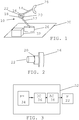
- Fig. 1 schematically shows a robot arrangement comprising a robot 10 and a robot controller 32.
- the robot 10 comprises a number of arm sections 12, 14 connected to each other via joints 16.
- the robot 10 shown in fig. 1 is simplified and therefore only two arm sections are shown, a first and a second arm section 12 and 14, connected to each other via joint 16. This means that in this example only one joint 16 which joins the first and second arm sections 12 and 14 is shown. It should however be realized that a robot normally comprises many more arm sections, typically six and consequently also several more joints that may be controlled.
- the first arm section 12 is here connected to a foundation 26.
- the robot 10 is attached to the foundation 26.
- the foundation may provide a first axis of rotation.
- this joint has been omitted from fig. 1 for the sake of clarity.
- the robot normally comprises a tool holder for allowing a tool 28 to be connected to the robot 10.
- Such a tool is typically connected to the outermost arm section of the robot, i.e. to the arm section furthest away from the foundation 26. Consequently, in fig. 1 one such tool 28 is shown as being attached to the second arm section 14.
- actuator 22 In order to move the second arm section 14 in relation to the first arm section 12 there is provided an actuator 22 at the joint 16, which actuator 22 may be implemented as a motor, for instance as a servo motor for moving the second arm around a second axis of rotation defined by the joint 16. Between this actuator and the joint 16 there is furthermore provided a gear box 20.
- a sensor connected to the joint.
- Such a sensor could be provided for sensing at least one property, such as a property of the robot, where variations in the property are being caused by the operation of the actuator 22.
- a property such as a property of the robot
- One possible property being sensed in this way is a position of the robot 10 and more specifically the position of the second arm section 14 in relation to the second axis.
- Another possible property is the speed of the motor 22.
- a further possible property is the acceleration of the motor.
- a further property is the torque of the second arm 14.
- a temperature sensor that senses the temperature of the location, i.e. the ambient temperature of the gearbox 20.
- the sensor may furthermore be placed or mounted on the actuator or the gear box.
- the joint 16, with actuator 22 and gear box 20 is also schematically shown in fig. 2 , which figure shows a perspective view of these elements.
- the robot controller 32 is connected to the robot 10 and more particularly to the actuator 22 and if there is a sensor also to this sensor.
- a block schematic of the robot controller 32 connected to the motor 22 is shown in fig. 3 .
- the robot controller 32 comprises a path planner unit PP 34 connected to a drift compensating unit DC 36.
- the drift compensating unit 36 is in turn connected to an arm control unit AC 38, which is finally connected to the motor M 22.
- the drift compensating unit 36 may also be considered to form a device for compensating robot movement deviations caused by a gear box.
- Fig. 4 shows a process control schematic of the path planner unit 34, drift compensating unit 36, arm control unit 38, motor 22, gear box 20 and second arm 14.
- the path planner unit 34 provides motor data about the motor. In this case it provides motor data in the form of a desired motor position value q r , a desired motor velocity value q ⁇ r and a desired motor acceleration value q ⁇ r to a dynamic model block 40.
- the motor velocity value q ⁇ r is also provided to a drift estimating block 42 of the drift compensating unit 36, which drift estimating block 42 also receives a motor torque value ⁇ of the motor and a gravitation torque value ⁇ grav from the dynamic model block 40.
- the drift compensating unit 36 also comprises a drift adjusting block 44 connected between a signal output of the path planning unit 34 and a first signal input of a position control block 46 of the arm control unit 38.
- the drift adjusting block 44 receives a drift compensating value ⁇ q from the drift estimating block 42 and a position value qr from the path planning unit 34 and provides the sum of these to the first signal input of the position control block 46 of the arm control unit 38.
- the position control block 46 also has a signal output connected to a signal input of the torque control block 48, which has a signal output connected to the motor 22.
- the motor 22 in turn provides a motor position q in to the gear box 20, which controls the robot arm 14 with a positional value q out .
- the motor position q in is also provided in a feedback loop back to a second input of the position control block 46.
- the dynamic model block 40 comprises a dynamic model of the robot. Such a model may be used by the pattern planner unit 34. For this reason the dynamic model block 40 may as an alternative be a part of the path planner unit 34 instead of the drift compensating unit 36.
- This problem may be increased by the fact that the time constants of the thermal drift may be short ( ⁇ 2 min for increase of temperature, 4 minutes for decrease), and a short stop, e.g., will change tool position significantly. The drift may thus increase faster than it decreases. This problem is handled by the robot movement compensation system of the invention.
- the drift estimating block 42 estimates the drift, and outputs the adjustment ⁇ q .
- the drift estimating block 42 may employ a dynamic drift model to estimate the internal temperature of the gear box from speed q ⁇ r and torque ⁇ . It is not necessary to estimate the temperature as such, but only to obtain a measure of the temperature, which measure has the same behavior as the temperature variation. Knowing the temperature or measure, the drift can then be estimated based on the torque.
- the model used may be of a grey-box type and calibrated by measuring the drift using an external measurement system.
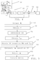
- fig. 5 shows a flow chart of a number of method steps in a method of compensating robot movement deviation being performed in the compensating unit 36.
- the path planning unit 34 determines a movement of the robot, for instance in order to move the robot along a robot path.
- the path is typically a path in which the tool 28 is to occupy a certain position at different instances of time.
- the path planner unit 34 provides a number of control commands for controlling motors to move corresponding arm sections, which movements together contribute to the desired tool movement.
- One of the motors being controlled is the motor 22 connected to the joint 16 via the gear box 20 for moving the second arm section 14.
- the path planning unit 34 provides a control value q r indicating a desired position of the second arm section 14, such as an angle in relation to the rotational axis defined by the joint 16. This is provided for use in controlling the movement of the second arm 14.
- the path planning unit 34 also provides a corresponding motor speed value q ⁇ r and acceleration value q ⁇ r , where all three values are provided as input to the dynamic model block 40 of the drift compensating unit 36 in order to obtain one or two torque values ⁇ and ⁇ grav of the second arm section 14 using the dynamic model of the robot.
- the values are here the total torque ⁇ of the motor 22 as well as the gravitational torque ⁇ grav of the motor. Both these torque values ⁇ and ⁇ grav and the motor speed value q ⁇ r are received by the drift estimating block 42 of the drift compensating unit 36.
- the drift estimating block 42 thus obtains motor data about the motor, here in the form of the motor speed q ⁇ r , step 50, as well as motor torque data, here in the form of the total motor torque ⁇ , step 52. Based on these two pieces of data it then determines a measure TM of the temperature of the gear box 20, step 54. After this has been done, the drift estimating block 42 obtains the gravitational torque value ⁇ grav from the dynamic model block 40, step 56, and thereafter determines a drift value DV based on the temperature measure TM and the gravitational torque ⁇ grav , step 58. The drift value is thus being obtained based on the gearbox temperature measure TM and the gravitational torque ⁇ grav of the motor.
- the drift estimating block 42 estimates a drift ⁇ q based on the drift value DV, step 59.
- the drift value DV is thereby used for obtaining an estimate of the drift ⁇ q .
- the drift value DV depends on the temperature measure TM and the gravitational torque ⁇ grav
- the estimated drift ⁇ q depends on the temperature measure TM and the gravitational torque ⁇ grav .
- the drift value DV is used as the estimated drift ⁇ q .
- the estimated drift ⁇ q is then provided to the drift adjusting block 44 for being subtracted from the control value q r, and in this way the drift adjusting block 44 adjusts the control value q r , step 60. It thus adjusts the control value qr that is used to control the positioning of the robot based on the estimated drift. This estimated drift ⁇ q thus compensates for the drift in the gear box output signal q out .
- the adjusted control value is then provided to the position control block 46 of the arm control unit 38, which after further processing delivers a process control signal to the torque control block 48, which in turn further processes the signal for providing as a control command to the motor 22, step 62.
- the motor 22 then controls the position of the arm section 14 with a position q in , which is translated by the gear box 20 to a position q out for controlling the arm section 14.
- the motor position q in is also fed back to the position control block 46 in a feedback control loop.
- the adjustment is a feed forward adjustment, which provides a fast compensation of the drift.
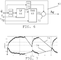
- Fig. 6 shows a block schematic of one realization of the drift estimating block 42. It comprises a first signal processing branch comprising an optional absolute value forming element AV 64 with an input that receives the motor speed q ⁇ r .
- the absolute value forming element AV 64 also has an output that is connected to a first input of a temperature dependent measure forming element.
- the temperature dependent measure forming element may be a dynamic model of grey box - black box type that uses motor speed and optionally also motor torque to determine or estimate a measure of the gear box temperature.
- the temperature dependent measure forming element is in the form of a low pass filter LP 66, which in turn has an output connected to the input of a temperature measure handling element 68.
- the second signal processing branch comprises a sign determining element 70 having an input that also receives the motor speed q ⁇ r .
- the sign determining element 70 is connected to a multiplying element 72, which is also connected to an output of the temperature measure handling element 68 and thereby it interconnects the first and second signal processing branches.
- TM a measure of the temperature based on the speed q ⁇ r and the motor torque ⁇ .
- This measure TM may be determined using the low pass filter 66. It is here possible that the motor speed q ⁇ r is directly used as an input signal to the low pass filter 66. However, in the example given in fig. 6 the motor speed is supplied to the absolute value forming element 64, which determines the absolute value
- the filter coefficients may be set based on the change of the motor speed values being input.
- these coefficients may be set in the following way:
- the output TM at time t may be determined from the input, i.e. (absolute) speed, at time t and the output at a previous time (t-1), where t-1 and t are two consecutive sampling times.
- the filter characteristics i.e. the coefficients coeff1 and coeff2 for heating and cooling may be set according to the time evolution of a pre-measured drift value for a specific gravity torque.
- the result of this filtering is the temperature measure TM, which is supplied to the temperature measure handling element 68.
- the temperature measure handling element 68 applies the temperature measure TM and gravitational torque ⁇ grav on known relationships between drift value DV, temperature measure TM and gravitational torque ⁇ grav in order to obtain a drift value.
- the temperature measure handling element 68 may comprise pre-measured drift values, which drift values have been measured for different known combinations of gravitational torque and temperature measure TM.
- the pre-measured drift values may be provided in the form of curves or equations outlining the dependency between the drift value DV and gravitational torque ⁇ grav .
- a curve or an equation may set out the dependency of gravitational torque ⁇ grav and drift value DV for a specific temperature measure TM.
- the pre-measured drift values may as an alternative be provided in the form of one or more tables.
- a table may comprise drift values depending on different temperature measure TM and gravitational torque values.
- a drift value may then be a table entry that is identified by the corresponding temperature measure and gravitational torque values in the columns and rows of the table.
- of the speed may be used for compensating the drift. This can be used to obtain a drift value that is independent of the direction of movement.
- the second signal processing branch it is possible to use the second signal processing branch.
- the motor speed q ⁇ r is provided to the sign determining element 70, which determines the sign of the speed q ⁇ r. This sign, which is thus a positive or a negative value, is then provided to the multiplying element 72 where it is multiplied with the drift value DV obtained from the temperature measure handling element 68. Thereby the sign of the speed q ⁇ r is multiplied with the drift value DV and the product is provided as the estimated drift ⁇ q .
- two drift estimating blocks 42 are connected in parallel, where one is provided with the second signal processing branch and the other lacks such a branch, where the output of these block are added to each other in order to obtain a total compensation that comprises both movement direction dependent and movement direction independent drift compensating components.
- the other drift estimating block thus lack sign determining element and there is an adding unit for adding the drift values obtained from the two drift estimating blocks to each other in order to obtain the estimated drift.
- drift components that are better modelled as a translation of the gearbox, or a rotation in other directions than the output direction, these components could be compensated for in the same way as described here.
- the difference is that, e.g. a translational drift, must be compensated by more than one joint position. This means that kinematics may have to be used to translate drift to motor position compensation.
- the torques may be estimated through the use of a dynamic model of the robot.
- This model maybe a rigid body dynamic model of the robot where all position, speed and acceleration dependent torques for a rigid robot are determined based on information about position, speed and acceleration.
- the position dependent torque is gravity and the sum of all torques is the total torque.
- drift compensating unit may be considered to form a device for compensating robot movement deviations caused by a gear box, it is clear that the dynamics model block may be omitted from the device.
- the drift compensating unit is such a device.
- one or more of the other units of the robot controller may be included in the device for compensating robot movement deviations caused by the gear box. It is for instance possible that the whole robot controller is considered to be such a device.
- the different units of the robot controller and thus also the drift compensating unit 36 may be provided in the form of one or more processors together with computer program memory including computer program code for performing the functions of these units. As an alternative they may be provided in the form of one or more Application Specific Integrated Circuits (ASIC) or Field-Programmable Gate Arrays (FPGA).
- ASIC Application Specific Integrated Circuit
- FPGA Field-Programmable Gate Arrays
- This computer program code may also be provided on one or more data carriers which perform the functionality of the robot controller and especially of the drift compensating unit when the program code thereon is being loaded in a computer forming the robot controller.
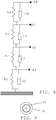
- One such data carrier 78 with computer program code 80, in the form of a CD ROM disc, is schematically shown in fig. 9 .
- Such computer program may as an alternative be provided on a server and downloaded therefrom into the computer forming the parameter determining device.
Description
- The present invention relates to the field of robots. The invention more particularly relates to a method, device, and computer program product for compensating robot movement deviations caused by a gear box as well as to a robot arrangement comprising such a device.
- A robot section, such as a part of a robot arm is often controlled by a motor, such as a servo motor, together with a gear box.
- The control of industrial robots may in theory be so precise that the deviation from a desired position is very small. This allows the robot to perform fine and precise operations.
- However, it has been found that the robot movement deviation varies because of the gear box temperature. This means that the movements are not as precise anymore. If a robot is to be used in production, this may lead to unacceptable low quality of the products produced.
- Various documents discuss handling of temperature drift in a motor, see for instance
US 5420490 , or in a robot in general, seeEP 2199036 . - The document
US20090076653 discloses a system for estimating the gearbox temperature of an industrial robot in which temperature sensors are not necessary. The documentJP2013154433 - There is in view of this still a need for providing a compensation of the drift caused by temperature variations in a gear box.
- The present invention is therefore directed towards compensating robot movement deviations caused by a gear box connected between a robot section and a motor controlling the movement of the robot section.
- The invention is defined by the independent claims. Further embodiments are defined by the dependent claims.
- Another object of the present invention is to provide a device for compensating robot movement deviations caused by a gear box connected between a robot section and a motor controlling the movement of the robot section.
- The device may be a part of the robot controller for the robot.
- Another object of the present invention is to provide a robot arrangement comprising an industrial robot and a device for compensating robot movement deviations caused by a gear box.
- Another object of the present invention is to provide a computer program product for compensating robot movement deviations caused by a gear box connected between a robot section and a motor controlling the movement of the robot section.
- The present invention has many advantages. It allows a simple and fast compensation of the drift caused by temperature deviations in the gearbox. This improves the operation of the robot, which may perform more precise movements. Furthermore, this improvement can be achieved through program updates in the robot controller. Thereby the additional costs required for implementing the added functionality are low.
- It should be emphasized that the term "comprises/comprising" when used in this specification is taken to specify the presence of stated features, integers, steps or components, but does not preclude the presence or addition of one or more other features, integers, steps, components or groups thereof.
- The present invention will now be described in more detail in relation to the enclosed drawings, in which:
-
fig. 1 schematically shows a robot arrangement comprising a robot and a robot controller, -
fig. 2 schematically shows a joint of the robot with a gear box and a motor, -
fig. 3 shows a block schematic of the robot controller being connected to the motor, where the robot controller comprises a path planner unit, a drift compensating unit and a control unit in the , -
fig. 4 schematically shows a control diagram for controlling the joint using the gear box and motor, the control diagram comprising the path calculating unit and various control blocks in the drift calculating unit and control unit, -
fig. 5 shows a number of method steps being performed in a method for compensating the drift, -
fig. 6 schematically shows a number of control elements provided in the drift compensating unit in order to compensate the drift, -
fig. 7 shows a curve of a comparison of the drift with and without compensation, and -
fig. 8 schematically shows a computer program product in the form of a CD Rom disc comprising computer program code for compensating drift. - In the following description, for purposes of explanation and not limitation, specific details are set forth such as particular architectures, interfaces, techniques, etc. in order to provide a thorough understanding of the present invention. However, it will be apparent to those skilled in the art that the present invention may be practiced in other embodiments that depart from these specific details. In other instances, detailed descriptions of well known devices, circuits, and methods are omitted so as not to obscure the description of the present invention with unnecessary detail.
-
Fig. 1 schematically shows a robot arrangement comprising arobot 10 and arobot controller 32. Therobot 10 comprises a number ofarm sections joints 16. Therobot 10 shown infig. 1 is simplified and therefore only two arm sections are shown, a first and asecond arm section joint 16. This means that in this example only onejoint 16 which joins the first andsecond arm sections - The
first arm section 12 is here connected to afoundation 26. In this way therobot 10 is attached to thefoundation 26. There is normally also a joint joining thefirst arm section 12 to thisfoundation 26 for allowing thefirst arm section 12 to be moved in relation to thefoundation 26. Thereby the foundation may provide a first axis of rotation. However, this joint has been omitted fromfig. 1 for the sake of clarity. The robot normally comprises a tool holder for allowing atool 28 to be connected to therobot 10. Such a tool is typically connected to the outermost arm section of the robot, i.e. to the arm section furthest away from thefoundation 26. Consequently, infig. 1 onesuch tool 28 is shown as being attached to thesecond arm section 14. - In order to move the
second arm section 14 in relation to thefirst arm section 12 there is provided anactuator 22 at thejoint 16, whichactuator 22 may be implemented as a motor, for instance as a servo motor for moving the second arm around a second axis of rotation defined by thejoint 16. Between this actuator and the joint 16 there is furthermore provided agear box 20. - In some variations it is also possible that there is one or more sensor connected to the joint. Such a sensor could be provided for sensing at least one property, such as a property of the robot, where variations in the property are being caused by the operation of the
actuator 22. One possible property being sensed in this way is a position of therobot 10 and more specifically the position of thesecond arm section 14 in relation to the second axis. Another possible property is the speed of themotor 22. A further possible property is the acceleration of the motor. A further property is the torque of thesecond arm 14. It is also possible to have a temperature sensor that senses the temperature of the location, i.e. the ambient temperature of thegearbox 20. The sensor may furthermore be placed or mounted on the actuator or the gear box. - The joint 16, with
actuator 22 andgear box 20 is also schematically shown infig. 2 , which figure shows a perspective view of these elements. - The
robot controller 32 is connected to therobot 10 and more particularly to theactuator 22 and if there is a sensor also to this sensor. - A block schematic of the
robot controller 32 connected to themotor 22 is shown infig. 3 . Therobot controller 32 comprises a pathplanner unit PP 34 connected to a drift compensatingunit DC 36. Thedrift compensating unit 36 is in turn connected to an armcontrol unit AC 38, which is finally connected to themotor M 22. Thedrift compensating unit 36 may also be considered to form a device for compensating robot movement deviations caused by a gear box. -
Fig. 4 shows a process control schematic of thepath planner unit 34,drift compensating unit 36,arm control unit 38,motor 22,gear box 20 andsecond arm 14. Infig. 4 there is also shown blocks of thedrift compensating unit 36 andarm control unit 38. Thepath planner unit 34 provides motor data about the motor. In this case it provides motor data in the form of a desired motor position value qr, a desired motor velocity value q̇r and a desired motor acceleration value q̈r to adynamic model block 40. The motor velocity value q̇r is also provided to adrift estimating block 42 of thedrift compensating unit 36, whichdrift estimating block 42 also receives a motor torque value τ of the motor and a gravitation torque value τgrav from thedynamic model block 40. Thedrift compensating unit 36 also comprises adrift adjusting block 44 connected between a signal output of thepath planning unit 34 and a first signal input of aposition control block 46 of thearm control unit 38. Thedrift adjusting block 44 receives a drift compensating value Δq from thedrift estimating block 42 and a position value qr from thepath planning unit 34 and provides the sum of these to the first signal input of theposition control block 46 of thearm control unit 38. Theposition control block 46 also has a signal output connected to a signal input of thetorque control block 48, which has a signal output connected to themotor 22. Themotor 22 in turn provides a motor position qin to thegear box 20, which controls therobot arm 14 with a positional value qout . The motor position qin is also provided in a feedback loop back to a second input of theposition control block 46. - The
dynamic model block 40 comprises a dynamic model of the robot. Such a model may be used by thepattern planner unit 34. For this reason thedynamic model block 40 may as an alternative be a part of thepath planner unit 34 instead of thedrift compensating unit 36. - As mentioned earlier, it has shown that there is robot movement deviation variation because of the variations of the gear box temperature. The difference between the gearbox input position (motor position) qin and gearbox output position (joint position) qout may then generally depend on the thermal state of the
gearbox 20, i.e., the temperature in different parts of thegearbox 20. If a change of thermal state will cause significant change of the tool position, this can affect the robot application negatively. If for instance the thermal drift in the z direction of the robot is around 0.3 mm and the robot repeatability is specified to be 0.05 mm, then the thermal drift will be interpreted as a repeatability of 0.3 mm. This problem may be increased by the fact that the time constants of the thermal drift may be short (∼2 min for increase of temperature, 4 minutes for decrease), and a short stop, e.g., will change tool position significantly. The drift may thus increase faster than it decreases. This problem is handled by the robot movement compensation system of the invention. - Based on motor speed q̇r, total motor torque τ, and gravity torque τgrav , the
drift estimating block 42 estimates the drift, and outputs the adjustment Δq. Thedrift estimating block 42 may employ a dynamic drift model to estimate the internal temperature of the gear box from speed q̇r and torque τ. It is not necessary to estimate the temperature as such, but only to obtain a measure of the temperature, which measure has the same behavior as the temperature variation. Knowing the temperature or measure, the drift can then be estimated based on the torque. The model used may be of a grey-box type and calibrated by measuring the drift using an external measurement system. - Now a first embodiment will be described with reference also being made to
fig. 5 , which shows a flow chart of a number of method steps in a method of compensating robot movement deviation being performed in the compensatingunit 36. - The
path planning unit 34 determines a movement of the robot, for instance in order to move the robot along a robot path. The path is typically a path in which thetool 28 is to occupy a certain position at different instances of time. In this thepath planner unit 34 provides a number of control commands for controlling motors to move corresponding arm sections, which movements together contribute to the desired tool movement. One of the motors being controlled is themotor 22 connected to the joint 16 via thegear box 20 for moving thesecond arm section 14. Thepath planning unit 34 provides a control value qr indicating a desired position of thesecond arm section 14, such as an angle in relation to the rotational axis defined by the joint 16. This is provided for use in controlling the movement of thesecond arm 14. Thepath planning unit 34 also provides a corresponding motor speed value q̇r and acceleration value q̈r, where all three values are provided as input to thedynamic model block 40 of thedrift compensating unit 36 in order to obtain one or two torque values τ and τgrav of thesecond arm section 14 using the dynamic model of the robot. The values are here the total torque τ of themotor 22 as well as the gravitational torque τ grav of the motor. Both these torque values τ and τgrav and the motor speed value q̇r are received by thedrift estimating block 42 of thedrift compensating unit 36. - The
drift estimating block 42 thus obtains motor data about the motor, here in the form of the motor speed q̇r,step 50, as well as motor torque data, here in the form of the total motor torque τ,step 52. Based on these two pieces of data it then determines a measure TM of the temperature of thegear box 20,step 54. After this has been done, thedrift estimating block 42 obtains the gravitational torque value τgrav from thedynamic model block 40,step 56, and thereafter determines a drift value DV based on the temperature measure TM and the gravitational torque τgrav,step 58. The drift value is thus being obtained based on the gearbox temperature measure TM and the gravitational torque τgrav of the motor. Thedrift estimating block 42 then estimates a drift Δq based on the drift value DV,step 59. The drift value DV is thereby used for obtaining an estimate of the drift Δq. As the drift value DV depends on the temperature measure TM and the gravitational torque τgrav, it is clear that also the estimated drift Δq depends on the temperature measure TM and the gravitational torque τgrav . In some variations the drift value DV is used as the estimated drift Δq. In other variations it is processed for obtaining the estimated drift Δq. The estimated drift Δq is then provided to thedrift adjusting block 44 for being subtracted from the control value qr, and in this way thedrift adjusting block 44 adjusts the control value qr,step 60. It thus adjusts the control value qr that is used to control the positioning of the robot based on the estimated drift. This estimated drift Δq thus compensates for the drift in the gear box output signal qout. - The adjusted control value is then provided to the
position control block 46 of thearm control unit 38, which after further processing delivers a process control signal to thetorque control block 48, which in turn further processes the signal for providing as a control command to themotor 22,step 62. Themotor 22 then controls the position of thearm section 14 with a position qin , which is translated by thegear box 20 to a position qout for controlling thearm section 14. Here the motor position qin is also fed back to theposition control block 46 in a feedback control loop. - It should be realized that the operation of the
position control block 46,torque control block 48 in relation to themotor 22 andgear box 20 is conventional and as such known. However the control values employed have been adjusted so that the effects of the drift of the gear box have been considered. - Furthermore, in the described embodiment the adjustment is a feed forward adjustment, which provides a fast compensation of the drift.
- One specific way in which the estimated drift could be obtained will now be described in relation to
fig. 6 . -
Fig. 6 shows a block schematic of one realization of thedrift estimating block 42. It comprises a first signal processing branch comprising an optional absolute value formingelement AV 64 with an input that receives the motor speed q̇r. The absolute value formingelement AV 64 also has an output that is connected to a first input of a temperature dependent measure forming element. - The temperature dependent measure forming element may be a dynamic model of grey box - black box type that uses motor speed and optionally also motor torque to determine or estimate a measure of the gear box temperature. In this first embodiment the temperature dependent measure forming element is in the form of a low
pass filter LP 66, which in turn has an output connected to the input of a temperaturemeasure handling element 68. There is also a second optional signal processing branch in parallel with the first signal processing branch. The second signal processing branch comprises asign determining element 70 having an input that also receives the motor speed q̇r. Thesign determining element 70 is connected to a multiplyingelement 72, which is also connected to an output of the temperaturemeasure handling element 68 and thereby it interconnects the first and second signal processing branches. - As mentioned earlier there is determined a measure TM of the temperature based on the speed q̇r and the motor torque τ. This measure TM may be determined using the
low pass filter 66. It is here possible that the motor speed q̇r is directly used as an input signal to thelow pass filter 66. However, in the example given infig. 6 the motor speed is supplied to the absolutevalue forming element 64, which determines the absolute value |q̇r | of the speed for input to thelow pass filter 66. Thelow pass filter 66 then filters the absolute value |q̇r | of the speed. The low pass filtering thus involves filtering using thelow pass filter 66. - In this filtering the filter coefficients may be set based on the change of the motor speed values being input. As an example these coefficients may be set in the following way:
 If input(t) > output(t-1)
 Set coeff_1 and coeff_2 for heating;
 else
 Set coeff_1 and coeff_2 for cooling;
 end
Claims (13)
- A method for compensating robot movement deviations caused by a gear box (20) connected between a robot section (14) and a motor (22) controlling the movement of the robot section (14), the method comprising the steps of:- obtaining (50) motor data (q̇r ) of the motor (22);- obtaining (52) motor torque data (τ);- determining (54) a measure (TM) of the temperature of the gear box (20) based on the motor data (q̇r ) and motor torque data (τ);- estimating (59) the drift (Δq) based on a drift value (DV) of the robot section, said drift value in turn being obtained (58) based on the gearbox temperature measure (TM) and a gravitational torque (τgrav ) of the motor, where the drift value or the drift value after processing is used as the estimated drift; and- adjusting (60) a control value (qr ) used to control the positioning of the robot based on the estimated drift (Δq);wherein the estimating of the drift comprises obtaining the drift value (DV) by applying the temperature measure and gravitational torque on known relationships between drift value, temperature measure and gravitational torque and the determining of the temperature measure comprises low pass filtering the motor data, where the result of the filtering is the temperature measure.
- The method according to claim 1, wherein low pass filtering comprises low pass filtering the absolute value of the motor data.
- The method according to claim 2, further comprising determining the sign of the motor data and multiplying the drift value with the sign of the motor data in order to obtain the estimated drift.
- The method according to claim 1 or 2, wherein the drift value is the estimated drift.
- The method according to any previous claim, wherein the motor data comprises the velocity of the motor movement.
- The method according to any previous claim, wherein motor data comprises motor position and the gravitational torque is obtained through employing the motor position in a dynamic model of the robot.
- A device (36) for compensating robot movement deviations caused by a gear box (20) connected between a robot section (14) and a motor (22) controlling the movement of the robot section (14), the device comprising:at least one drift estimating block (42) configured to- obtain motor data (q̇r ) of the motor (22);- obtain motor torque data (τ);- determine a measure (TM) of the temperature of the gear box (20) based on the motor data (q̇r ) and motor torque data (τ); and- estimate the drift (Δq) based on a drift value (DV) of the robot section, said drift value in turn being obtained based on the gearbox temperature measure (TM) and a gravitational torque (τgrav ) of the motor, where the drift value or the drift value after processing is used as the estimated drift; anda drift adjusting block (44) configured to adjust a control value used to control the positioning of the robot based on the estimated drift (Δq),wherein the drift estimating block (42) comprises a temperature measure handling element (68) configured to obtain the drift value (DV) by applying the temperature measure and gravitational torque on known relationships between drift value, temperature measure and gravitational torque and a temperature dependent measure forming element (66) configured to determine the measure through low pass filtering the motor data, where the result of the filtering is the temperature measure.
- The device according to claim 7, wherein the drift estimating block (42) comprises an absolute value forming element (64) connected to temperature dependent measure forming element (66) in order for the temperature dependent measure forming element (66) to low pass filter the absolute value of the motor data.
- The device according to claim 8, wherein the drift estimating block (42) further comprises a sign determining element 70 configured to determine the sign of the motor data and a multiplying element (72) configured to multiply the drift value with the sign of the motor data in order to obtain the estimated drift.
- The device according to claim 9, wherein there is a further drift estimating block without sign determining element and an adding unit for adding the drift values from the two drift estimating blocks in order to obtain the estimated drift.
- The device according to any of claims 7 - 10,
wherein the motor data comprises motor position and further comprising a dynamic model block (40) configured to obtain the gravitational torque through employing the motor position in a dynamic model of the robot. - A robot arrangement comprising an industrial robot and a device (36) for compensating robot movement deviations,
the industrial robot (10) comprisinga number of moveable arm sections (12, 14), at least one motor (20) for moving a corresponding arm section, anda gear box (22) between the motor and the arm section,the device (36) for compensating robot movement deviations comprising
a drift estimating block (42) and drift adjusting block (44) according to any of claims 7 - 11. - A computer program product for compensating robot movement deviations caused by a gear box (20) connected between a robot section (14) and a motor (22) controlling the movement of the robot section (14), the computer program product comprising a data carrier (78) with computer program code (80) which when run in a device (36) for compensating robot movement deviations, causes the device to:- obtain motor data (q̇r ) of the motor (22);- obtain motor torque data (τ);- determine a measure (TM) of the temperature of the gear box (20) based on the motor data(q̇r ) and motor torque data (τ);- estimate the drift (Δq) based on a drift value (DV) of the robot section, said drift value in turn being obtained based on the gearbox temperature measure (TM) and a gravitational torque (τgrav ) of the motor, where the drift value or the drift value after processing is used as the estimated drift; and- adjust a control value (qr ) used to control the positioning of the robot based on the estimated drift (Δq), wherein the estimating of the drift comprises obtaining the drift value (DV) by applying the temperature measure and gravitational torque on known relationships between drift value, temperature measure and gravitational torque and the determining of the temperature measure comprises low pass filtering the motor data, where the result of the filtering is the temperature measure.
Applications Claiming Priority (1)
| Application Number | Priority Date | Filing Date | Title |
|---|---|---|---|
| PCT/EP2014/058097 WO2015161864A1 (en) | 2014-04-22 | 2014-04-22 | Compensating robot movement deviations |
Publications (2)
| Publication Number | Publication Date |
|---|---|
| EP3134780A1 EP3134780A1 (en) | 2017-03-01 |
| EP3134780B1 true EP3134780B1 (en) | 2019-11-20 |
Family
ID=50639464
Family Applications (1)
| Application Number | Title | Priority Date | Filing Date |
|---|---|---|---|
| EP14721281.5A Active EP3134780B1 (en) | 2014-04-22 | 2014-04-22 | Compensating robot movement deviations |
Country Status (4)
| Country | Link |
|---|---|
| US (1) | US10331107B2 (en) |
| EP (1) | EP3134780B1 (en) |
| CN (1) | CN106233214B (en) |
| WO (1) | WO2015161864A1 (en) |
Families Citing this family (10)
| Publication number | Priority date | Publication date | Assignee | Title |
|---|---|---|---|---|
| US10603794B2 (en) * | 2015-08-27 | 2020-03-31 | Accel Robotics Corporation | Robotic camera system |
| US9975244B1 (en) * | 2016-08-02 | 2018-05-22 | X Development Llc | Real-time generation of trajectories for actuators of a robot |
| CN109773827B (en) * | 2017-11-10 | 2021-12-07 | 上银科技股份有限公司 | Method and system for load estimation gravity compensation of mechanical arm |
| DE112018007159B4 (en) | 2018-02-26 | 2022-10-06 | Mitsubishi Electric Corporation | CORRECTIVE FUNCTION GENERATION DEVICE, ROBOT CONTROL SYSTEM AND ROBOT SYSTEM |
| EP3807732A1 (en) * | 2018-06-15 | 2021-04-21 | Universal Robots A/S | Dual mode free-drive of robot arm |
| JP7199178B2 (en) * | 2018-08-28 | 2023-01-05 | 株式会社東芝 | ROBOT CONTROL DEVICE, ROBOT DEVICE, ROBOT CONTROL PARAMETER ADJUSTMENT METHOD, AND PROGRAM |
| EP3623113A1 (en) * | 2018-09-14 | 2020-03-18 | Universal Robots A/S | Obtaining the gear stiffness of a robot joint gear of a robot arm |
| WO2020185440A1 (en) * | 2019-03-08 | 2020-09-17 | Covidien Lp | Methods for analog temperature compensation of bias and offsets of a differential sensor |
| CN113891786A (en) * | 2019-04-17 | 2022-01-04 | 优傲机器人公司 | Method for controlling robot arm based on adaptive friction |
| LU102199B1 (en) | 2020-11-10 | 2022-05-10 | Nabtesco Prec Europe Gmbh | Method and control device for controlling a movement of a multi-axis robot |
Family Cites Families (15)
| Publication number | Priority date | Publication date | Assignee | Title |
|---|---|---|---|---|
| KR0160997B1 (en) | 1992-09-18 | 1998-12-15 | 윤종용 | Compensation method for servo-worm up drift in robot position control system |
| DE19848642A1 (en) | 1998-10-22 | 2000-04-27 | Heidenhain Gmbh Dr Johannes | Temperature-dependent variation compensation method for machine tool or robot geometry corrects user input commands before conversion from input coordinate system into machine coordinate system |
| SE0104320D0 (en) | 2001-12-19 | 2001-12-19 | Abb Ab | Method for industrial robot systems |
| KR100486505B1 (en) * | 2002-12-31 | 2005-04-29 | 엘지전자 주식회사 | Gyro offset compensation method of robot cleaner |
| SE0301531L (en) * | 2003-05-22 | 2004-11-23 | Abb Ab | A Control method for a robot |
| DE102004056861A1 (en) * | 2004-11-25 | 2006-06-08 | Kuka Roboter Gmbh | Method and device for controlling, manipulating manipulators |
| JP4650062B2 (en) | 2005-03-31 | 2011-03-16 | 株式会社安川電機 | Robot controller and robot positioning accuracy correction method |
| US20100032242A1 (en) * | 2008-08-05 | 2010-02-11 | Lin Chung-Chuan | Pressure Relief Device for a Gear Box |
| DE102008060052A1 (en) | 2008-12-02 | 2010-06-17 | Kuka Roboter Gmbh | Method and device for compensating a kinematic deviation |
| CN101774065B (en) * | 2010-03-17 | 2012-09-12 | 昆山工研院工业机器人研究所有限公司 | Robot welding line tracking deviation compensation method |
| DE102011003506A1 (en) | 2011-02-02 | 2012-08-16 | Kuka Roboter Gmbh | industrial robots |
| DE102011012809A1 (en) * | 2011-03-02 | 2012-09-06 | Dürr Systems GmbH | Robot gear with a pressure compensation device |
| JP2013154433A (en) | 2012-01-30 | 2013-08-15 | Canon Inc | Robot |
| CN102806560B (en) * | 2012-08-24 | 2014-08-06 | 电子科技大学 | Method capable of automatically eliminating motion accumulated error of robot |
| CN202994132U (en) * | 2012-12-19 | 2013-06-12 | 华南理工大学 | Robot pose error measuring system based on rectangular coordinate mode |
-
2014
- 2014-04-22 EP EP14721281.5A patent/EP3134780B1/en active Active
- 2014-04-22 US US15/301,553 patent/US10331107B2/en active Active
- 2014-04-22 WO PCT/EP2014/058097 patent/WO2015161864A1/en active Application Filing
- 2014-04-22 CN CN201480078126.9A patent/CN106233214B/en active Active
Non-Patent Citations (1)
| Title |
|---|
| None * |
Also Published As
| Publication number | Publication date |
|---|---|
| CN106233214B (en) | 2019-04-12 |
| CN106233214A (en) | 2016-12-14 |
| EP3134780A1 (en) | 2017-03-01 |
| US20170108848A1 (en) | 2017-04-20 |
| WO2015161864A1 (en) | 2015-10-29 |
| US10331107B2 (en) | 2019-06-25 |
Similar Documents
| Publication | Publication Date | Title |
|---|---|---|
| EP3134780B1 (en) | Compensating robot movement deviations | |
| Olabi et al. | Feedrate planning for machining with industrial six-axis robots | |
| Zhang et al. | Pre-compensation of contour errors in five-axis CNC machine tools | |
| JP5935958B2 (en) | Trajectory control device | |
| JP6238421B2 (en) | Method and system for determining at least one characteristic of a joint | |
| TWI435517B (en) | Load inertia estimation method and control parameter adjustment method | |
| US8896255B2 (en) | Servo controller having function for correcting amount of expansion/contraction of ball screw | |
| JP2013128387A (en) | Controller of motor having function of estimating inertia, coefficient of friction and spring constant simultaneously | |
| US10409258B2 (en) | Method for compensating for a deviation in an operating point | |
| KR101522511B1 (en) | Control method and control device | |
| JP6214948B2 (en) | Friction compensation device, friction compensation method, and servo control device | |
| US9796087B2 (en) | Control system for power unit | |
| Marton et al. | Control of robotic systems with unknown friction and payload | |
| JP6277428B2 (en) | Motor drive device | |
| KR102114068B1 (en) | Computed-torque based controller, and its parameter determination and performance analysis methods | |
| WO2016110320A1 (en) | Method for estimation of external forces and torques on a robot arm | |
| JP2006285301A (en) | Robot control device and precision correction method for positioning robot | |
| Luo et al. | Predictive seam tracking with iteratively learned feedforward compensation for high-precision robotic laser welding | |
| Hua et al. | Visual tracking control for an uncalibrated robot system with unknown camera parameters | |
| Dong et al. | Interpolating gain-scheduled H∞ loop shaping design for high speed ball screw feed drives | |
| CN109388099B (en) | Machining of workpieces with model-supported error compensation | |
| CN107438502A (en) | The method of industrial robot is controlled by touching | |
| JP4483314B2 (en) | Servo control device | |
| JP7034383B2 (en) | Servo controller | |
| CN109143968B (en) | Control device, position control system, position control method, and recording medium |
Legal Events
| Date | Code | Title | Description |
|---|---|---|---|
| STAA | Information on the status of an ep patent application or granted ep patent |
Free format text: STATUS: THE INTERNATIONAL PUBLICATION HAS BEEN MADE |
|
| PUAI | Public reference made under article 153(3) epc to a published international application that has entered the european phase |
Free format text: ORIGINAL CODE: 0009012 |
|
| STAA | Information on the status of an ep patent application or granted ep patent |
Free format text: STATUS: REQUEST FOR EXAMINATION WAS MADE |
|
| 17P | Request for examination filed |
Effective date: 20161122 |
|
| AK | Designated contracting states |
Kind code of ref document: A1 Designated state(s): AL AT BE BG CH CY CZ DE DK EE ES FI FR GB GR HR HU IE IS IT LI LT LU LV MC MK MT NL NO PL PT RO RS SE SI SK SM TR |
|
| AX | Request for extension of the european patent |
Extension state: BA ME |
|
| DAX | Request for extension of the european patent (deleted) | ||
| GRAP | Despatch of communication of intention to grant a patent |
Free format text: ORIGINAL CODE: EPIDOSNIGR1 |
|
| STAA | Information on the status of an ep patent application or granted ep patent |
Free format text: STATUS: GRANT OF PATENT IS INTENDED |
|
| INTG | Intention to grant announced |
Effective date: 20190703 |
|
| GRAS | Grant fee paid |
Free format text: ORIGINAL CODE: EPIDOSNIGR3 |
|
| GRAA | (expected) grant |
Free format text: ORIGINAL CODE: 0009210 |
|
| STAA | Information on the status of an ep patent application or granted ep patent |
Free format text: STATUS: THE PATENT HAS BEEN GRANTED |
|
| AK | Designated contracting states |
Kind code of ref document: B1 Designated state(s): AL AT BE BG CH CY CZ DE DK EE ES FI FR GB GR HR HU IE IS IT LI LT LU LV MC MK MT NL NO PL PT RO RS SE SI SK SM TR |
|
| REG | Reference to a national code |
Ref country code: GB Ref legal event code: FG4D |
|
| REG | Reference to a national code |
Ref country code: CH Ref legal event code: EP |
|
| REG | Reference to a national code |
Ref country code: IE Ref legal event code: FG4D |
|
| REG | Reference to a national code |
Ref country code: DE Ref legal event code: R096 Ref document number: 602014057058 Country of ref document: DE |
|
| REG | Reference to a national code |
Ref country code: AT Ref legal event code: REF Ref document number: 1204877 Country of ref document: AT Kind code of ref document: T Effective date: 20191215 |
|
| REG | Reference to a national code |
Ref country code: NL Ref legal event code: MP Effective date: 20191120 |
|
| REG | Reference to a national code |
Ref country code: LT Ref legal event code: MG4D |
|
| PG25 | Lapsed in a contracting state [announced via postgrant information from national office to epo] |
Ref country code: FI Free format text: LAPSE BECAUSE OF FAILURE TO SUBMIT A TRANSLATION OF THE DESCRIPTION OR TO PAY THE FEE WITHIN THE PRESCRIBED TIME-LIMIT Effective date: 20191120 Ref country code: BG Free format text: LAPSE BECAUSE OF FAILURE TO SUBMIT A TRANSLATION OF THE DESCRIPTION OR TO PAY THE FEE WITHIN THE PRESCRIBED TIME-LIMIT Effective date: 20200220 Ref country code: LT Free format text: LAPSE BECAUSE OF FAILURE TO SUBMIT A TRANSLATION OF THE DESCRIPTION OR TO PAY THE FEE WITHIN THE PRESCRIBED TIME-LIMIT Effective date: 20191120 Ref country code: NL Free format text: LAPSE BECAUSE OF FAILURE TO SUBMIT A TRANSLATION OF THE DESCRIPTION OR TO PAY THE FEE WITHIN THE PRESCRIBED TIME-LIMIT Effective date: 20191120 Ref country code: NO Free format text: LAPSE BECAUSE OF FAILURE TO SUBMIT A TRANSLATION OF THE DESCRIPTION OR TO PAY THE FEE WITHIN THE PRESCRIBED TIME-LIMIT Effective date: 20200220 Ref country code: LV Free format text: LAPSE BECAUSE OF FAILURE TO SUBMIT A TRANSLATION OF THE DESCRIPTION OR TO PAY THE FEE WITHIN THE PRESCRIBED TIME-LIMIT Effective date: 20191120 Ref country code: SE Free format text: LAPSE BECAUSE OF FAILURE TO SUBMIT A TRANSLATION OF THE DESCRIPTION OR TO PAY THE FEE WITHIN THE PRESCRIBED TIME-LIMIT Effective date: 20191120 Ref country code: GR Free format text: LAPSE BECAUSE OF FAILURE TO SUBMIT A TRANSLATION OF THE DESCRIPTION OR TO PAY THE FEE WITHIN THE PRESCRIBED TIME-LIMIT Effective date: 20200221 |
|
| PG25 | Lapsed in a contracting state [announced via postgrant information from national office to epo] |
Ref country code: IS Free format text: LAPSE BECAUSE OF FAILURE TO SUBMIT A TRANSLATION OF THE DESCRIPTION OR TO PAY THE FEE WITHIN THE PRESCRIBED TIME-LIMIT Effective date: 20200320 Ref country code: HR Free format text: LAPSE BECAUSE OF FAILURE TO SUBMIT A TRANSLATION OF THE DESCRIPTION OR TO PAY THE FEE WITHIN THE PRESCRIBED TIME-LIMIT Effective date: 20191120 Ref country code: RS Free format text: LAPSE BECAUSE OF FAILURE TO SUBMIT A TRANSLATION OF THE DESCRIPTION OR TO PAY THE FEE WITHIN THE PRESCRIBED TIME-LIMIT Effective date: 20191120 |
|
| PG25 | Lapsed in a contracting state [announced via postgrant information from national office to epo] |
Ref country code: AL Free format text: LAPSE BECAUSE OF FAILURE TO SUBMIT A TRANSLATION OF THE DESCRIPTION OR TO PAY THE FEE WITHIN THE PRESCRIBED TIME-LIMIT Effective date: 20191120 |
|
| PG25 | Lapsed in a contracting state [announced via postgrant information from national office to epo] |
Ref country code: EE Free format text: LAPSE BECAUSE OF FAILURE TO SUBMIT A TRANSLATION OF THE DESCRIPTION OR TO PAY THE FEE WITHIN THE PRESCRIBED TIME-LIMIT Effective date: 20191120 Ref country code: PT Free format text: LAPSE BECAUSE OF FAILURE TO SUBMIT A TRANSLATION OF THE DESCRIPTION OR TO PAY THE FEE WITHIN THE PRESCRIBED TIME-LIMIT Effective date: 20200412 Ref country code: DK Free format text: LAPSE BECAUSE OF FAILURE TO SUBMIT A TRANSLATION OF THE DESCRIPTION OR TO PAY THE FEE WITHIN THE PRESCRIBED TIME-LIMIT Effective date: 20191120 Ref country code: RO Free format text: LAPSE BECAUSE OF FAILURE TO SUBMIT A TRANSLATION OF THE DESCRIPTION OR TO PAY THE FEE WITHIN THE PRESCRIBED TIME-LIMIT Effective date: 20191120 Ref country code: CZ Free format text: LAPSE BECAUSE OF FAILURE TO SUBMIT A TRANSLATION OF THE DESCRIPTION OR TO PAY THE FEE WITHIN THE PRESCRIBED TIME-LIMIT Effective date: 20191120 Ref country code: ES Free format text: LAPSE BECAUSE OF FAILURE TO SUBMIT A TRANSLATION OF THE DESCRIPTION OR TO PAY THE FEE WITHIN THE PRESCRIBED TIME-LIMIT Effective date: 20191120 |
|
| REG | Reference to a national code |
Ref country code: AT Ref legal event code: MK05 Ref document number: 1204877 Country of ref document: AT Kind code of ref document: T Effective date: 20191120 |
|
| REG | Reference to a national code |
Ref country code: DE Ref legal event code: R097 Ref document number: 602014057058 Country of ref document: DE |
|
| PG25 | Lapsed in a contracting state [announced via postgrant information from national office to epo] |
Ref country code: SM Free format text: LAPSE BECAUSE OF FAILURE TO SUBMIT A TRANSLATION OF THE DESCRIPTION OR TO PAY THE FEE WITHIN THE PRESCRIBED TIME-LIMIT Effective date: 20191120 Ref country code: SK Free format text: LAPSE BECAUSE OF FAILURE TO SUBMIT A TRANSLATION OF THE DESCRIPTION OR TO PAY THE FEE WITHIN THE PRESCRIBED TIME-LIMIT Effective date: 20191120 |
|
| PLBE | No opposition filed within time limit |
Free format text: ORIGINAL CODE: 0009261 |
|
| STAA | Information on the status of an ep patent application or granted ep patent |
Free format text: STATUS: NO OPPOSITION FILED WITHIN TIME LIMIT |
|
| 26N | No opposition filed |
Effective date: 20200821 |
|
| PG25 | Lapsed in a contracting state [announced via postgrant information from national office to epo] |
Ref country code: SI Free format text: LAPSE BECAUSE OF FAILURE TO SUBMIT A TRANSLATION OF THE DESCRIPTION OR TO PAY THE FEE WITHIN THE PRESCRIBED TIME-LIMIT Effective date: 20191120 Ref country code: AT Free format text: LAPSE BECAUSE OF FAILURE TO SUBMIT A TRANSLATION OF THE DESCRIPTION OR TO PAY THE FEE WITHIN THE PRESCRIBED TIME-LIMIT Effective date: 20191120 Ref country code: PL Free format text: LAPSE BECAUSE OF FAILURE TO SUBMIT A TRANSLATION OF THE DESCRIPTION OR TO PAY THE FEE WITHIN THE PRESCRIBED TIME-LIMIT Effective date: 20191120 Ref country code: MC Free format text: LAPSE BECAUSE OF FAILURE TO SUBMIT A TRANSLATION OF THE DESCRIPTION OR TO PAY THE FEE WITHIN THE PRESCRIBED TIME-LIMIT Effective date: 20191120 |
|
| REG | Reference to a national code |
Ref country code: CH Ref legal event code: PL |
|
| PG25 | Lapsed in a contracting state [announced via postgrant information from national office to epo] |
Ref country code: FR Free format text: LAPSE BECAUSE OF NON-PAYMENT OF DUE FEES Effective date: 20200430 Ref country code: LU Free format text: LAPSE BECAUSE OF NON-PAYMENT OF DUE FEES Effective date: 20200422 Ref country code: IT Free format text: LAPSE BECAUSE OF FAILURE TO SUBMIT A TRANSLATION OF THE DESCRIPTION OR TO PAY THE FEE WITHIN THE PRESCRIBED TIME-LIMIT Effective date: 20191120 Ref country code: LI Free format text: LAPSE BECAUSE OF NON-PAYMENT OF DUE FEES Effective date: 20200430 Ref country code: CH Free format text: LAPSE BECAUSE OF NON-PAYMENT OF DUE FEES Effective date: 20200430 |
|
| REG | Reference to a national code |
Ref country code: BE Ref legal event code: MM Effective date: 20200430 |
|
| PG25 | Lapsed in a contracting state [announced via postgrant information from national office to epo] |
Ref country code: BE Free format text: LAPSE BECAUSE OF NON-PAYMENT OF DUE FEES Effective date: 20200430 |
|
| GBPC | Gb: european patent ceased through non-payment of renewal fee |
Effective date: 20200422 |
|
| PG25 | Lapsed in a contracting state [announced via postgrant information from national office to epo] |
Ref country code: GB Free format text: LAPSE BECAUSE OF NON-PAYMENT OF DUE FEES Effective date: 20200422 Ref country code: IE Free format text: LAPSE BECAUSE OF NON-PAYMENT OF DUE FEES Effective date: 20200422 |
|
| PG25 | Lapsed in a contracting state [announced via postgrant information from national office to epo] |
Ref country code: TR Free format text: LAPSE BECAUSE OF FAILURE TO SUBMIT A TRANSLATION OF THE DESCRIPTION OR TO PAY THE FEE WITHIN THE PRESCRIBED TIME-LIMIT Effective date: 20191120 Ref country code: MT Free format text: LAPSE BECAUSE OF FAILURE TO SUBMIT A TRANSLATION OF THE DESCRIPTION OR TO PAY THE FEE WITHIN THE PRESCRIBED TIME-LIMIT Effective date: 20191120 Ref country code: CY Free format text: LAPSE BECAUSE OF FAILURE TO SUBMIT A TRANSLATION OF THE DESCRIPTION OR TO PAY THE FEE WITHIN THE PRESCRIBED TIME-LIMIT Effective date: 20191120 |
|
| PG25 | Lapsed in a contracting state [announced via postgrant information from national office to epo] |
Ref country code: MK Free format text: LAPSE BECAUSE OF FAILURE TO SUBMIT A TRANSLATION OF THE DESCRIPTION OR TO PAY THE FEE WITHIN THE PRESCRIBED TIME-LIMIT Effective date: 20191120 |
|
| PGFP | Annual fee paid to national office [announced via postgrant information from national office to epo] |
Ref country code: DE Payment date: 20230420 Year of fee payment: 10 |