EP3134364B1 - Verfahren zur herstellung einer optischen faser und vorformen - Google Patents
Verfahren zur herstellung einer optischen faser und vorformen Download PDFInfo
- Publication number
- EP3134364B1 EP3134364B1 EP15720546.9A EP15720546A EP3134364B1 EP 3134364 B1 EP3134364 B1 EP 3134364B1 EP 15720546 A EP15720546 A EP 15720546A EP 3134364 B1 EP3134364 B1 EP 3134364B1
- Authority
- EP
- European Patent Office
- Prior art keywords
- soot
- blank
- core
- soot blank
- core cane
- Prior art date
- Legal status (The legal status is an assumption and is not a legal conclusion. Google has not performed a legal analysis and makes no representation as to the accuracy of the status listed.)
- Active
Links
Images


Classifications
-
- C—CHEMISTRY; METALLURGY
- C03—GLASS; MINERAL OR SLAG WOOL
- C03B—MANUFACTURE, SHAPING, OR SUPPLEMENTARY PROCESSES
- C03B37/00—Manufacture or treatment of flakes, fibres, or filaments from softened glass, minerals, or slags
- C03B37/01—Manufacture of glass fibres or filaments
- C03B37/012—Manufacture of preforms for drawing fibres or filaments
- C03B37/0128—Manufacture of preforms for drawing fibres or filaments starting from pulverulent glass
- C03B37/01282—Manufacture of preforms for drawing fibres or filaments starting from pulverulent glass by pressing or sintering, e.g. hot-pressing
-
- C—CHEMISTRY; METALLURGY
- C03—GLASS; MINERAL OR SLAG WOOL
- C03B—MANUFACTURE, SHAPING, OR SUPPLEMENTARY PROCESSES
- C03B37/00—Manufacture or treatment of flakes, fibres, or filaments from softened glass, minerals, or slags
- C03B37/01—Manufacture of glass fibres or filaments
- C03B37/012—Manufacture of preforms for drawing fibres or filaments
- C03B37/01205—Manufacture of preforms for drawing fibres or filaments starting from tubes, rods, fibres or filaments
- C03B37/01211—Manufacture of preforms for drawing fibres or filaments starting from tubes, rods, fibres or filaments by inserting one or more rods or tubes into a tube
-
- C—CHEMISTRY; METALLURGY
- C03—GLASS; MINERAL OR SLAG WOOL
- C03B—MANUFACTURE, SHAPING, OR SUPPLEMENTARY PROCESSES
- C03B37/00—Manufacture or treatment of flakes, fibres, or filaments from softened glass, minerals, or slags
- C03B37/01—Manufacture of glass fibres or filaments
- C03B37/012—Manufacture of preforms for drawing fibres or filaments
- C03B37/01205—Manufacture of preforms for drawing fibres or filaments starting from tubes, rods, fibres or filaments
- C03B37/01225—Means for changing or stabilising the shape, e.g. diameter, of tubes or rods in general, e.g. collapsing
- C03B37/01228—Removal of preform material
- C03B37/01231—Removal of preform material to form a longitudinal hole, e.g. by drilling
-
- C—CHEMISTRY; METALLURGY
- C03—GLASS; MINERAL OR SLAG WOOL
- C03B—MANUFACTURE, SHAPING, OR SUPPLEMENTARY PROCESSES
- C03B37/00—Manufacture or treatment of flakes, fibres, or filaments from softened glass, minerals, or slags
- C03B37/01—Manufacture of glass fibres or filaments
- C03B37/012—Manufacture of preforms for drawing fibres or filaments
- C03B37/014—Manufacture of preforms for drawing fibres or filaments made entirely or partially by chemical means, e.g. vapour phase deposition of bulk porous glass either by outside vapour deposition [OVD], or by outside vapour phase oxidation [OVPO] or by vapour axial deposition [VAD]
- C03B37/01446—Thermal after-treatment of preforms, e.g. dehydrating, consolidating, sintering
-
- C—CHEMISTRY; METALLURGY
- C03—GLASS; MINERAL OR SLAG WOOL
- C03B—MANUFACTURE, SHAPING, OR SUPPLEMENTARY PROCESSES
- C03B37/00—Manufacture or treatment of flakes, fibres, or filaments from softened glass, minerals, or slags
- C03B37/01—Manufacture of glass fibres or filaments
- C03B37/02—Manufacture of glass fibres or filaments by drawing or extruding, e.g. direct drawing of molten glass from nozzles; Cooling fins therefor
- C03B37/025—Manufacture of glass fibres or filaments by drawing or extruding, e.g. direct drawing of molten glass from nozzles; Cooling fins therefor from reheated softened tubes, rods, fibres or filaments, e.g. drawing fibres from preforms
- C03B37/027—Fibres composed of different sorts of glass, e.g. glass optical fibres
-
- C—CHEMISTRY; METALLURGY
- C03—GLASS; MINERAL OR SLAG WOOL
- C03B—MANUFACTURE, SHAPING, OR SUPPLEMENTARY PROCESSES
- C03B2203/00—Fibre product details, e.g. structure, shape
- C03B2203/30—Polarisation maintaining [PM], i.e. birefringent products, e.g. with elliptical core, by use of stress rods, "PANDA" type fibres
- C03B2203/31—Polarisation maintaining [PM], i.e. birefringent products, e.g. with elliptical core, by use of stress rods, "PANDA" type fibres by use of stress-imparting rods, e.g. by insertion
-
- C—CHEMISTRY; METALLURGY
- C03—GLASS; MINERAL OR SLAG WOOL
- C03B—MANUFACTURE, SHAPING, OR SUPPLEMENTARY PROCESSES
- C03B2203/00—Fibre product details, e.g. structure, shape
- C03B2203/34—Plural core other than bundles, e.g. double core
-
- C—CHEMISTRY; METALLURGY
- C03—GLASS; MINERAL OR SLAG WOOL
- C03B—MANUFACTURE, SHAPING, OR SUPPLEMENTARY PROCESSES
- C03B2203/00—Fibre product details, e.g. structure, shape
- C03B2203/42—Photonic crystal fibres, e.g. fibres using the photonic bandgap PBG effect, microstructured or holey optical fibres
-
- Y—GENERAL TAGGING OF NEW TECHNOLOGICAL DEVELOPMENTS; GENERAL TAGGING OF CROSS-SECTIONAL TECHNOLOGIES SPANNING OVER SEVERAL SECTIONS OF THE IPC; TECHNICAL SUBJECTS COVERED BY FORMER USPC CROSS-REFERENCE ART COLLECTIONS [XRACs] AND DIGESTS
- Y02—TECHNOLOGIES OR APPLICATIONS FOR MITIGATION OR ADAPTATION AGAINST CLIMATE CHANGE
- Y02P—CLIMATE CHANGE MITIGATION TECHNOLOGIES IN THE PRODUCTION OR PROCESSING OF GOODS
- Y02P40/00—Technologies relating to the processing of minerals
- Y02P40/50—Glass production, e.g. reusing waste heat during processing or shaping
- Y02P40/57—Improving the yield, e-g- reduction of reject rates
Definitions
- the present invention generally relates to methods for making optical fibers using soot blanks and core canes, and particularly to a method for making optical fiber preforms for drawing into optical fibers.
- Multicore optical fibers permit parallel transmission using space-division multiplexing.
- Multicore optical fibers increase transmission capacity by N-fold, where "N" is the number of cores in the multicore optical fiber.
- space-division multiplexing through multicore optical fibers is a method well-suited for increasing bandwidth density.
- One current method for producing multicore optical fibers includes positioning glass core canes in soot blanks, then consolidating the soot blanks and glass core canes to form glass preforms.
- the preforms are drawn to make optical fibers.
- flaws are frequently present near the glass core cane surface following consolidation of the preform, limiting the quality of multicore fibers produced using such methods.
- US 2011/132,038 A relates to a method and an apparatus for making an optical fiber preform.
- US 4,501,601 relates to a process for manufacturing glass fiber optical waveguides. The process comprises forming a cohesive core body, forming a cohesive cladding body and sintering the bodies into a glass preform.
- US 2012/0047959 relates to the manufacture of an optical fiber comprising placing a partially manufactured preform in an inner cavity of an apparatus, placing particulate glass material in the cavity around the preform and pressing.
- a method of forming an optical fiber includes the steps of forming a silica-based soot blank with at least one silica-based soot core cane at least partially embedded in the soot blank.
- the soot blank with the at least one soot core cane positioned therein is consolidated to form a preform.
- the preform is then drawn to form an optical fiber.
- the expression silica-based soot core cane thereby refers to a core cane having an unconsolidated or partially consolidated inner portion and an unconsolidated or partially consolidated outer portion.
- the density of the at least one soot core cane is thereby within 10% of the density of the soot blank prior to consolidating the soot blank and the soot core to form the preform.
- a method of forming an optical fiber includes forming a silica-based soot blank with at least one core cane at least partially embedded in the soot blank, wherein the at least one core cane includes an outer portion which is not fully consolidated prior to its positioning in the soot blank.
- the average bulk density of the at least one core cane is within 10% of the bulk density of the soot blank.
- the soot blank with the at least one core cane positioned therein is then consolidated to form a preform.
- the preform is drawn to form an optical fiber.
- Yet another aspect of the disclosure includes a method of forming a preform for an optical fiber.
- a silica-based soot body is press formed around at least one silica-based soot core cane, wherein the soot core cane is not consolidated to form a sintered glass prior to the press forming.
- the soot body is consolidated with the soot core cane positioned therein to form a preform.
- the method disclosed herein reduces the occurrence of flaws in the multicore optical fiber resulting from stresses encountered during consolidation, and is an economic and scalable method for production.
- Figure 1A depicts a first embodiment of a method for forming optical fibers 16.
- the method includes the steps of (1) forming a silica-based soot blank 10 and (2) forming a soot core cane 12. (3) The soot core cane 12 is positioned in the soot blank 10, and (4) the soot blank 10 and soot core cane 12 are consolidated to form a preform 14. (5) The preform 14 is then drawn to form an optical fiber 16.
- Figure 1B depicts another embodiment of a method for forming optical fibers 16.
- the method includes the steps of (6) forming a soot core cane 12, and then (7) press forming soot around the soot core cane 12 to form a soot blank 10.
- the soot blank 10 and soot core cane 12 are then consolidated to form a preform 14.
- the preform 14 is then drawn to form an optical fiber 16.
- the silica-based soot blank 10 is formed with at least one silica-based soot core cane 12 at least partially embedded in the soot blank 10.
- the soot blank 10 is then consolidated with the soot core cane 12 positioned therein to form a preform 14.
- the preform 14 is then drawn to form an optical fiber 16.
- the method described herein can be used with one core cane 12 to make a single core fiber 16 according to one embodiment or with a plurality of core canes 12 to make a multicore optical fiber 16 according to another embodiment.
- the soot blank 10 is formed from an unconsolidated or a partially consolidated silica-based material which is appropriate for cladding of optical fibers 16.
- the soot blank 10 is a SiO 2 material.
- the SiO 2 material may be doped with elements such as F, B, Ge, Er, Ti, Al, Li, K, Rb, Cs, Cl, Br, Na, Nd, Bi, Sb, Yb, or combinations thereof, or other elements known for use in cladding of optical fibers 16.
- the soot blank 10 as described herein can be formed via a soot pressing process, an outside vapor deposition ("OVD") process, or any other known method for preparing a soot blank 10.
- the soot blank 10 for use herein preferably has a top surface 18 with a diameter of from 150 mm to 300 mm, and preferably has a length of greater than 1 m, and more preferably has a length between 1 m and to 2 m.
- the soot blank 10 may have a generally rectangular or other polygonal-shaped top surface 18.
- soot pressing process particulate soot material is deposited into a mold cavity, and pressure is applied against the particulate soot material in the mold to form the soot blank 10.
- the soot pressing process may include forming a solid soot blank 10, or forming a soot blank 10 with holes in predetermined locations by pressing the soot material around the core canes 12 or around removable mold rods 38.
- the soot pressing process is usually carried out at pressures of from 172.37 kPa to 1,723.7 kPa (25 psig to 250 psig) and the particulate soot material can be radially compressed, axially compressed, laterally compressed, or compressed in any other method to form the soot blank 10.
- radial pressure is applied with a maximum pressure of 150 psig, using a pressurization rate of from 1 psig/minute to 10 psig/minute, and holding the soot material at the maximum pressure for a time of 30 minutes to a time of 2 hours.
- the soot blank 10 is then depressurized at a depressurization rate of 1 psig/minute to 10 psig/minute until ambient room pressure is reached.
- the compacted soot material formed via press forming is optionally partially consolidated to form soot blanks 10 which have a desired density for further processing. Alternatively, depending on the formation, the soot blank 10 may have a sufficient density for further processing without partial consolidation.
- an inert rod is layered with silica-based soot particles applied around the perimeter of the inert rod.
- the soot particles are formed by passing ultrapure vapors, such as silicon chloride through a burner, where the vapors react in the flame to form fine silica-based soot particles that are then deposited on the inert rod.
- the inert rod is rotated during deposition, to form a uniform soot blank 10 around the inert rod.
- the inert rod is preferably removed from the soot blank 10, leaving a central hole 20 through a center axis of the soot blank 10.
- the soot density after the OVD process is typically around 0.5 g/cm 3 .
- the soot blanks 10 formed via OVD processing are optionally partially consolidated to form soot blanks which have a desired density for further processing. Alternatively, depending on the formation, the soot blank 10 may have a sufficient density for further processing without partial consolidation.
- the core cane 12 is also formed from a silica-based material.
- the core cane 12, like the soot blank 10, can be formed via press forming methods, OVD processing methods, a combination of press forming and OVD processing methods, or other production processes for soot material.
- the core canes 12 for use in the present disclosure can be designed for multimode fiber applications, polarization maintaining fiber applications, photonic crystal fiber applications, as well as single mode multicore fiber applications and single-core fiber applications.
- the embodiment of the core cane 12 depicted in Figure 3 includes an inner portion 30 and an outer portion 32, with the inner portion 30 formed of a first soot material, and the outer portion 32 formed of a second soot material. At least the inner portion 30 ultimately becomes the transmissive portion of the optical fiber 16, and is therefore preferably formed with a doped silica-based material. Any known dopants for increasing transmission can be used in the inner portion 30, including germanium and other known dopants.
- the inner portion 30 of the core cane 12 is a soot material which has not been consolidated or which has been only partially consolidated.
- the outer portion 32 of the core cane 12 as shown in the embodiment depicted in Figure 3 is a silica-based soot material, and has a different composition than the inner portion 30 of the core cane 12, including a different dopant or no dopant. In certain embodiments, the outer portion 32 has a different density than the inner portion 30. The inner portion 30 is also optionally consolidated to a different degree than the outer portion 32. In certain embodiments, the compositions of the inner portion 30 and the outer portion 32 are the same. When the material of the outer portion 32 of the core cane 12 is the same as the inner portion 30, both portions are used to transmit signals through the core cane 12.
- the inner portion 30 is press formed or formed via the OVD processing method.
- the inner portion 30 is then optionally partially consolidated.
- the outer portion 32 is then applied around a circumferential edge 34 of the inner portion 30 by pressing a second soot material around the inner portion 30 or by using the inner portion 30 as the inert rod during the OVD processing method and applying a second soot material around the inner portion 30.
- Soot pressing conditions for the core canes 12 are generally similar to the soot pressing conditions for soot blanks 10 described herein.
- core cane refers to soot core canes 12.
- core cane 12 has an unconsolidated or partially consolidated inner portion 30 and unconsolidated or partially consolidated outer portion 32, the core cane 12 is referred to herein as a "soot core cane.”
- fully consolidated means that the soot material has been substantially fully sintered to form a glass material, by holding the material at its sintering temperature for a time sufficient for the soot material to be converted to a glass material.
- Partial consolidation means that the sintering process is incomplete, and although the density of the soot material has been increased, the soot material has not been fully converted into a glass material. Partial consolidation can be used for all or part of the core cane 12 or the soot blank 10, separately, or after the core cane 12 is embedded in the soot blank 10.
- the core cane 12 or soot blank 10 is heated to a temperature below the normal sintering peak temperature for the material and is held at that temperature for a predetermined time, optionally under a helium atmosphere.
- the exposure time and temperature will change depending on the size of the soot blank 10 or core cane 12 and on the composition or presence of any dopants in the silica-based soot material of the soot blank 10 or the core cane 12.
- Partially consolidating the soot material results in a porous soot material which is strengthened by the formation of glass necks between individual particles of the soot material.
- the soot blank 10 or core cane 12 can be held at a temperature that is elevated with respect to room temperature but which is less than the partial consolidation temperature for an additional period of time to allow the soot blank 10 or core cane 12 to further consolidate and to cool more slowly than if the soot blank 10 or core cane 12 was returned immediately to room temperature.
- the soot blank 10 is formed prior to inserting the soot core canes 12.
- the soot blank 10 as used in the process illustrated in Figure 1A could be manufactured via soot pressing methods, OVD processing methods, or other known soot blank forming methods.
- the soot material is pressed to form the soot blank 10 with a top surface 18.
- the soot blank 10 is optionally partially consolidated to reach the desired density.
- a plurality of holes 36 are drilled into the top surface 18 of the soot blank 10 to accommodate positioning of soot core canes 12 in the soot blank 10.
- the plurality of holes 36 are formed by pressing the soot material around mold rods 38, and then removing the mold rods 38 to form a soot blank 10 with a plurality of holes 36 therethrough in predetermined positions for locating the soot core canes 12.
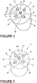
- the OVD process could also be used to form the soot blank 10, which is optionally partially consolidated to the desired density. As described above, a plurality of holes 36 are drilled into the top surface 18 of the OVD-formed soot blank 10 after it is formed. When formed via OVD processing methods, the soot blank 10 will also have a central hole 20, as shown in Figure 4 , after removal of the inert rod. When the soot blank 10 is formed via an OVD process, an additional glass rod 40 is optionally inserted into the central hole 20 left after removing the inert rod around which the soot blank 10 is formed. The glass rod 40 is preferably formed from the same material as the soot material used to form the soot blank 10.
- the glass rod 40 operates as a filler of the cladding material that makes up the soot blank 10, and is generally not the same material or construction as a the core canes 12, though the central hole 20 could be used for insertion of an additional core cane 12 if desired.
- the soot blank 10 is formed around soot core canes 12.
- the soot blank 10 as disclosed in Figure 1B is preferably manufactured via the soot pressing method.
- the soot core canes 12, which are optionally partially consolidated, are positioned in a predetermined arrangement and the soot material is pressed around the soot core canes 12 to embed them within the compacted soot blank 12.
- the soot blank 10 and soot core canes 12 are optionally partially consolidated to increase their density.
- alternate embodiments of the soot blank 10 as shown in the embodiments depicted in Figures 4 and 7 can accommodate additional elements 42 such as stress rods, metallic rods, markers, conductive or shielding wires or powders, semiconducting rods or powders, or index moots.
- the additional elements 42 generally have an elongated shape and are also located in at least one hole 44 in the soot blank 10.
- the soot drilling methods as described herein can be used to drill additional holes 44 in the soot blank 10 for the additional elements 42, mold rods can be used to form the holes 44 for the additional elements 42, or the soot blank 10 can be press formed around the additional elements 42.
- a preferred bulk density for the soot blank 10 described herein is between 0.5 g/cm 3 and 1.6 g/cm 3 . If holes 36, 44 will be drilled into the soot blank 10, a preferred bulk density range is from 0.5 g/cm 3 to 1.6 g/cm 3 , or more preferably from 1.0 g/cm 3 to 1.6 g/cm 3 , and more preferred is a bulk density of between 1.2 g/cm 3 and 1.5 g/cm 3 . If the soot blank 10 is press formed around mold rods or around the core canes 12, a preferred bulk density for the soot blank 10 is between 0.7 g/cm 3 and 1.0 g/cm 3 . These preferred densities may be reached through the formation process or through partial consolidation of the soot blank 10.
- the core canes 12 used for making preforms 14 and optical fibers 16 in the method of the invention have an average bulk density which is within 10% of the bulk density of the soot blank 10, and more preferably, have an average bulk density which is within 5% of the bulk density of the soot blank 10.
- Dc (A x Dop) + (B x Dip), Where Dc is the average bulk density of the core cane 12, Dop is the bulk density of the outer portion 32 of the core cane 12, and Dip is the bulk density of the inner portion 30 of the core cane 12.
- R1 is the radius of the inner portion 30, and R2 is the radius of the outer portion 32, as shown in the embodiment depicted in Figure 3 .
- FIG. 4 One embodiment of the soot blank 10 with core canes 12 embedded therein is shown in Figure 4 .
- the soot blank 10 with core canes 12 embedded therein is optionally partially consolidated prior to final consolidation, as described above with respect to either the soot blank 10 or the core canes 12 individually.
- the embodiment of the soot blank 10 shown in Figure 4 has a square 4-core configuration, with 4 core canes 12 embedded in the soot blank 10.
- the embodiment of a preform 14 depicted in Figure 5 is a consolidated glass preform 14 formed from the soot blank 10 shown in Figure 4 .
- the soot blank 10 and the core canes 12 are heated to a final sintering temperature and held at the temperature for a time sufficient to allow glass sintering of the soot blank 10 and the core canes 12.
- Sintering temperatures preferably range from 1400°C to 1600°C, and the soot blank 10 and core cane 12 are preferably held at these temperatures for a time of 10 minutes to 120 minutes.
- Consolidation is optionally carried out under a helium gas flow, which is preferably from 10 standard cubic liters per minute ("sclm") to 50 sclm.
- preparatory steps such as helium purging and/or chlorine drying of the soot blank 10 are carried out prior to heating the soot blank 10 to the sintering temperature.
- the chlorine drying may be carried out at a temperature of between 1100°C and 1200°C for a period of from 60 minutes to 240 minutes, with a chlorine gas flow of 2 sclm.
- Helium gas flow may be concurrent with the chlorine gas flow, preferably at a rate of 10 standard cubic feet per minute ("scfm") to 50 scfm.
- the consolidated preform 14 is held at an elevated temperature (higher than room temperature, lower than the sintering temperature) after sintering, which slows the cooling of the consolidated preform 14.
- the embodiment depicted in Figure 6 is the optical fiber 16 drawn from the preform 14 depicted in Figure 5 using known fiber-drawing methods, such as stretching the preform 14 in a redraw furnace.
- the resulting optical fiber 16 is a multicore optical fiber 16 with four transmissive cores 50 embedded within an overcladding 52.
- the diameter of the preform 14 is reduced in the drawing process to lengthen the fiber and the diameter of the core canes 12 within the preform 14 are reduced through the drawing process to form the transmissive cores 50.
- the centerline hole in the core canes 12 may be closed during the consolidation and subsequent fiber draw. Centerline hole closure during the draw has some advantages over centerline closure during redraw with vacuum, because centerline hole closure without vacuum have less non-axisymmetric features near the center of the core cane 12 and have less polarization mode dispersion.
- Figure 7 depicts the cross-section of an alternate embodiment of an optical fiber 16 drawn from a preform 14 according to the present disclosure.
- the embodiment depicted in Figure 7 includes an additional element 42, which is a marker that can be used to align multiple optical fibers 16 end-to-end.
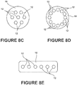
- Figure 8A-8E Many configurations for the placement of core canes 12 within the soot blank 10 are possible, and various configurations are illustrated in Figures 8A-8E .
- Figure 8A depicts a square configuration with four core canes 12.
- Figure 8B depicts a 2x4 configuration with eight core canes 12.
- Figure 8C depicts a hexagonal lattice configuration with seven core canes 12.
- Figure 8D depicts a ring configuration with twelve core canes 12.
- Figure 8E depicts a ribbon fiber configuration with six core canes 12. Alternate configurations are also possible, as determined for the operation of the desired optical fiber 16.
- the similar density of the core cane 12 and the soot blank 10 described herein reduces distortion due to shrinkage differences between the soot blank 10 and the core canes 12 during consolidation. By reducing the shrinkage differences, flaws in the glass preform 14 are reduced.
- Use of the soot blanks 10 and core canes 12 as described herein provide flexibility in core cane 12 placement and scalability which allow precision manufacturing of the multicore optical fibers 16. Additionally, increased precision in the production of the preform 14 can be leveraged in the reduction ratio to final multicore geometry for the multicore optical fiber 16 and precision of transmissive core 50 alignment in the multicore optical fiber 16.
- optical fibers 16 and optical fiber preforms 14 described herein can be used for making optical fibers 16 with one core 50, with multiple cores 50, with additional elements 42, such as markers, index moots, stress rods, or other features as further described herein or as known in the art.
- Optical fibers 16 that can be made using these methods include single polarization fibers, polarization maintaining fibers, bend insensitive fibers, multicore fibers, multicore fiber ribbons and photonic crystal fibers.
Landscapes
- Chemical & Material Sciences (AREA)
- Engineering & Computer Science (AREA)
- Materials Engineering (AREA)
- Geochemistry & Mineralogy (AREA)
- Manufacturing & Machinery (AREA)
- General Life Sciences & Earth Sciences (AREA)
- Life Sciences & Earth Sciences (AREA)
- Organic Chemistry (AREA)
- Chemical Kinetics & Catalysis (AREA)
- General Chemical & Material Sciences (AREA)
- Physics & Mathematics (AREA)
- Thermal Sciences (AREA)
- Manufacture, Treatment Of Glass Fibers (AREA)
Claims (10)
- Verfahren zum Erzeugen eines Lichtleiters, die folgenden Schritte umfassend:Erzeugen einer Rußfüllform auf Silicabasis mit mindestens einem Rußaderstock auf Silicabasis, der wenigstens teilweise in der Rußfüllform eingebettet ist;Verfestigen der Rußfüllform mit dem darin positionierten mindestens einen Rußaderstock, um eine Vorform zu bilden; undZiehen der Vorform, um einen Lichtleiter zu bilden;wobei der Ausdruck Rußaderstock auf Silicabasis einen Aderstock bezeichnet, der einen nicht verfestigten oder teilweise verfestigten inneren Teil und einen nicht verdichteten oder teilweise verdichteten äußeren Teil aufweist; undwobei die Dichte des mindestens einen Rußaderstocks innerhalb von 10% der Dichte der Rußfüllform vor dem Verfestigen der Rußfüllform und des Rußaderstocks liegt, um die Vorform zu bilden.
- Verfahren nach Anspruch 1, wobei eine Mehrzahl von Rußaderstöcken auf Silicabasis wenigstens teilweise in der Rußfüllform eingebettet ist, um einen mehradrigen Lichtleiter zu bilden.
- Verfahren nach Anspruch 2, wobei der Schritt des Erzeugens der Rußfüllform mit einer Mehrzahl von Rußaderstöcken zu bilden, die wenigstens teilweise in der Rußfüllform eingebettet sind, die folgenden Schritte umfasst:Positionieren der Mehrzahl von Rußaderstöcken in einer vorbestimmten Ausrichtung; undPressen eines Rußmaterials auf Silicabasis um die Mehrzahl von Rußaderstöcken, um die Rußfüllform zu bilden.
- Verfahren nach einem der Ansprüche 2 bis 3, wobei der Schritt des Erzeugens der Rußfüllform mit einer Mehrzahl von Rußaderstöcken, die wenigstens teilweise in die Rußfüllform eingebettet sind, die folgenden Schritte umfasst:Positionieren einer Mehrzahl von Formstäben in einer vorbestimmten Ausrichtung;Pressen eines Rußmaterials auf Silicabasis um die Mehrzahl von Formstäben, um eine Rußfüllform zu bilden;Entfernen der Mehrzahl von Formstäben, um die Rußfüllform zu bilden, wobei eine Mehrzahl von Löchern in der Rußfüllform verbleibt; undEinführen der Mehrzahl von Rußaderstöcken in die Mehrzahl von Löchern in der Rußfüllform.
- Verfahren nach einem der Ansprüche 2 bis 4, wobei der Schritt des Erzeugens der Rußfüllform mit einer Mehrzahl von Rußaderstöcken, die wenigstens teilweise in die Rußfüllform eingebettet sind, die folgenden Schritte umfasst:Erzeugen einer Rußfüllform aus einem Material auf Silicabasis mit einer oberen Oberfläche und einer Rohdichte zwischen 0,5 g/cm3 und 1,6 g/cm3;Bohren einer Mehrzahl von Löchern in die obere Oberfläche der Rußfüllform; undPositionieren eines Rußaderstockelements in jedes der Mehrzahl von Löchern.
- Verfahren nach einem der vorstehenden Ansprüche, wobei die Dichte des mindestens einen Rußaderstocks innerhalb von 5% der Dichte der Rußfüllform vor dem Verdichten der Rußfüllform und des Rußaderstocks liegt, um die Vorform zu bilden.
- Verfahren nach einem der vorstehenden Ansprüche, wobei die Rußfüllform und/oder der mindestens eine Rußaderstock vorverfestigt werden, um die gewünschte Dichte vor dem Zusammenbau der Rußfüllform und des mindestens einen Rußaderstocks zu erreichen.
- Verfahren nach einem der vorstehenden Ansprüche, wobei der mindestens eine Rußaderstock durch ein Pressverfahren erzeugt wird.
- Verfahren nach einem der vorstehenden Ansprüche, wobei der mindestens eine Rußaderstock durch ein externes Bedampfungsverfahren erzeugt wird.
- Verfahren nach einem der vorstehenden Ansprüche, wobei ein innerer Teil des mindestens einen Rußaderstocks eine andere chemische Zusammensetzung aufweist als ein äußerer Teil des mindestens einen Rußaderstocks.
Applications Claiming Priority (2)
| Application Number | Priority Date | Filing Date | Title |
|---|---|---|---|
| US14/261,734 US10053386B2 (en) | 2014-04-25 | 2014-04-25 | Method for forming optical fiber and preforms |
| PCT/US2015/027421 WO2015164684A1 (en) | 2014-04-25 | 2015-04-24 | Method for forming optical fiber and preforms |
Publications (2)
| Publication Number | Publication Date |
|---|---|
| EP3134364A1 EP3134364A1 (de) | 2017-03-01 |
| EP3134364B1 true EP3134364B1 (de) | 2020-06-10 |
Family
ID=53051949
Family Applications (1)
| Application Number | Title | Priority Date | Filing Date |
|---|---|---|---|
| EP15720546.9A Active EP3134364B1 (de) | 2014-04-25 | 2015-04-24 | Verfahren zur herstellung einer optischen faser und vorformen |
Country Status (5)
| Country | Link |
|---|---|
| US (1) | US10053386B2 (de) |
| EP (1) | EP3134364B1 (de) |
| JP (1) | JP6764346B2 (de) |
| CN (1) | CN106232537A (de) |
| WO (1) | WO2015164684A1 (de) |
Cited By (1)
| Publication number | Priority date | Publication date | Assignee | Title |
|---|---|---|---|---|
| DE102023126606A1 (de) * | 2023-09-29 | 2025-04-03 | Leibniz-Institut für Photonische Technologien e.V. (Engl.Leibniz Institute of Photonic Technology) | Verfahren zur Herstellung einer gebohrten Faser |
Families Citing this family (11)
| Publication number | Priority date | Publication date | Assignee | Title |
|---|---|---|---|---|
| EP3745170A4 (de) | 2018-01-25 | 2021-10-06 | Furukawa Electric Co., Ltd. | Mehrkernfaser und verfahren zu deren herstellung |
| JP7024546B2 (ja) * | 2018-03-27 | 2022-02-24 | 住友電気工業株式会社 | マルチコア光ファイバの製造方法 |
| JP7172088B2 (ja) * | 2018-03-28 | 2022-11-16 | 住友電気工業株式会社 | 光ファイバ製造方法 |
| CN113490649B (zh) | 2019-02-28 | 2024-03-08 | 康宁股份有限公司 | 形成基于坯棒的玻璃光纤预制件的基于真空的方法 |
| CN110261955A (zh) * | 2019-06-20 | 2019-09-20 | 长飞光纤光缆股份有限公司 | 一种保偏多芯光纤 |
| CN110261956B (zh) * | 2019-06-20 | 2021-02-26 | 长飞光纤光缆股份有限公司 | 一种阵列型保偏多芯光纤 |
| EP4212489A1 (de) | 2022-01-18 | 2023-07-19 | Heraeus Quarzglas GmbH & Co. KG | Verfahren und halbzeug zur herstellung einer mehrkernfaser |
| EP4212488A1 (de) | 2022-01-18 | 2023-07-19 | Heraeus Quarzglas GmbH & Co. KG | Verfahren und halbzeug zur herstellung einer mehrkernfaser |
| EP4227273B1 (de) | 2022-02-14 | 2025-07-23 | Heraeus Quarzglas GmbH & Co. KG | Verfahren und zwischenprodukt zur herstellung einer mehrkernfaser mit einem marker |
| CN116986824B (zh) * | 2023-07-13 | 2025-09-30 | 长飞光纤光缆股份有限公司 | 半导体稀土掺杂复合多芯光纤及其预制棒、制备方法与应用 |
| CN120491239A (zh) | 2024-02-14 | 2025-08-15 | 住友电气工业株式会社 | 多芯光纤 |
Citations (3)
| Publication number | Priority date | Publication date | Assignee | Title |
|---|---|---|---|---|
| WO2013130141A1 (en) * | 2011-11-30 | 2013-09-06 | Corning Incorporated | Pressed, multilayered silica soot preforms for the manufacture of single sinter step, complex refractive index profile optical fiber |
| WO2015073230A1 (en) * | 2013-11-14 | 2015-05-21 | Corning Incorporated | Methods and apparatuses for forming optical preforms from glass soot |
| WO2015157073A1 (en) * | 2014-04-08 | 2015-10-15 | Corning Incorporated | Method for making soot preforms and glass optical fibers |
Family Cites Families (31)
| Publication number | Priority date | Publication date | Assignee | Title |
|---|---|---|---|---|
| US463852A (en) | 1891-11-24 | Synchronous telegraph | ||
| DE3217965A1 (de) * | 1982-05-13 | 1983-11-17 | Standard Elektrik Lorenz Ag, 7000 Stuttgart | Verfahren zur herstellung von glasfaser-lichtwellenleitern |
| DE3240355C1 (de) | 1982-11-02 | 1983-11-17 | Heraeus Quarzschmelze Gmbh, 6450 Hanau | Verfahren zur Herstellung eines laenglichen Glaskoerpers mit inhomogener Brechungsindexverteilung |
| CA1236695A (en) * | 1984-09-17 | 1988-05-17 | Koichi Abe | Optical fiber |
| US4749396A (en) * | 1985-01-25 | 1988-06-07 | Polaroid Corporation | Method of forming an optical fiber preform |
| CA1290942C (en) * | 1985-03-18 | 1991-10-22 | Michihisa Kyoto | Method for producing glass preform for optical fiber |
| US4961767A (en) | 1987-05-20 | 1990-10-09 | Corning Incorporated | Method for producing ultra-high purity, optical quality, glass articles |
| EP0369091A1 (de) | 1988-11-15 | 1990-05-23 | Battelle Memorial Institute | Verfahren zum Herstellen von amorphen Quarzgegenständen |
| US5244485A (en) | 1991-04-30 | 1993-09-14 | The Furukawa Electric Co., Ltd. | Method of manufacturing a silica glass preform |
| JPH05170470A (ja) * | 1991-04-30 | 1993-07-09 | Furukawa Electric Co Ltd:The | 石英系ガラス母材の製造方法 |
| CA2088238C (en) | 1992-01-30 | 1998-08-18 | Masato Oku | Method of manufacturing optical fiber preform |
| JPH06191870A (ja) | 1992-10-30 | 1994-07-12 | Furukawa Electric Co Ltd:The | 光ファイバ用母材の製造方法 |
| JPH0971431A (ja) | 1995-09-07 | 1997-03-18 | Furukawa Electric Co Ltd:The | 石英ガラス系マルチコア光ファイバの製造方法 |
| US5944667A (en) | 1996-02-16 | 1999-08-31 | L'oreal | Device for evaluating the creasing of the skin in vivo |
| DE19810132C2 (de) * | 1997-03-10 | 2002-02-07 | Samsung Electronics Co Ltd | Vorrichtung und Verfahren zur Herstellung eines rohrförmigen Glasmonolithen unter Anwendung eines Sol-Gel-Prozesses |
| US6154594A (en) | 1998-07-15 | 2000-11-28 | Corning Incorporated | Multicore glass optical fiber and methods of manufacturing such fibers |
| US6418258B1 (en) | 2000-06-09 | 2002-07-09 | Gazillion Bits, Inc. | Microstructured optical fiber with improved transmission efficiency and durability |
| US20020168139A1 (en) * | 2001-03-30 | 2002-11-14 | Clarkson William Andrew | Optical fiber terminations, optical couplers and optical coupling methods |
| US7069746B2 (en) | 2001-10-22 | 2006-07-04 | Degussa Ag | Method for producing ultra-high purity, optical quality glass articles |
| US20030164006A1 (en) | 2001-10-26 | 2003-09-04 | Buchanan Karl H. | Direct bonding of glass articles for drawing |
| DE60336510D1 (de) | 2003-06-30 | 2011-05-05 | Prysmian Spa | Verfahren und vorrichtung zum bohren von vorformen für loch-lichtleitfasern |
| JP4407328B2 (ja) | 2004-03-15 | 2010-02-03 | 住友電気工業株式会社 | 透明ガラス体の製造方法 |
| EP1700828A1 (de) | 2005-03-09 | 2006-09-13 | Degussa AG | Verfahren zur Herstellung von Glaskörpern ultrahoher Reinheit und optischer Qualität |
| DE102008029756B3 (de) | 2008-06-25 | 2009-04-30 | Heraeus Quarzglas Gmbh & Co. Kg | Verfahren zur Herstellung eines Zylinders aus Quarzglas sowie Haltevorrichtung zur Durchführung des Verfahrens |
| US8578736B2 (en) | 2008-09-23 | 2013-11-12 | Corning Incorporated | Soot radial pressing for optical fiber overcladding |
| US8904828B2 (en) | 2008-10-30 | 2014-12-09 | Corning Incorporated | Methods for forming cladding portions of optical fiber preform assemblies |
| US8468852B2 (en) * | 2009-12-03 | 2013-06-25 | Corning Incorporated | Soot pressing for optical fiber overcladding |
| WO2012021317A1 (en) | 2010-08-12 | 2012-02-16 | Corning Incorporated | Treatment of silica based soot or an article made of silica based soot |
| US8869566B2 (en) | 2010-08-27 | 2014-10-28 | Corning Incorporated | Soot radial pressing for optical fiber overcladding |
| US9120693B2 (en) | 2010-11-08 | 2015-09-01 | Corning Incorporated | Multi-core optical fiber ribbons and methods for making the same |
| JP5579210B2 (ja) * | 2012-02-28 | 2014-08-27 | 日本電信電話株式会社 | 光ファイバ母材の製造方法 |
-
2014
- 2014-04-25 US US14/261,734 patent/US10053386B2/en active Active
-
2015
- 2015-04-24 EP EP15720546.9A patent/EP3134364B1/de active Active
- 2015-04-24 CN CN201580021880.3A patent/CN106232537A/zh active Pending
- 2015-04-24 JP JP2016563843A patent/JP6764346B2/ja active Active
- 2015-04-24 WO PCT/US2015/027421 patent/WO2015164684A1/en not_active Ceased
Patent Citations (3)
| Publication number | Priority date | Publication date | Assignee | Title |
|---|---|---|---|---|
| WO2013130141A1 (en) * | 2011-11-30 | 2013-09-06 | Corning Incorporated | Pressed, multilayered silica soot preforms for the manufacture of single sinter step, complex refractive index profile optical fiber |
| WO2015073230A1 (en) * | 2013-11-14 | 2015-05-21 | Corning Incorporated | Methods and apparatuses for forming optical preforms from glass soot |
| WO2015157073A1 (en) * | 2014-04-08 | 2015-10-15 | Corning Incorporated | Method for making soot preforms and glass optical fibers |
Cited By (1)
| Publication number | Priority date | Publication date | Assignee | Title |
|---|---|---|---|---|
| DE102023126606A1 (de) * | 2023-09-29 | 2025-04-03 | Leibniz-Institut für Photonische Technologien e.V. (Engl.Leibniz Institute of Photonic Technology) | Verfahren zur Herstellung einer gebohrten Faser |
Also Published As
| Publication number | Publication date |
|---|---|
| JP6764346B2 (ja) | 2020-09-30 |
| WO2015164684A1 (en) | 2015-10-29 |
| US10053386B2 (en) | 2018-08-21 |
| JP2017513798A (ja) | 2017-06-01 |
| US20150307387A1 (en) | 2015-10-29 |
| EP3134364A1 (de) | 2017-03-01 |
| CN106232537A (zh) | 2016-12-14 |
Similar Documents
| Publication | Publication Date | Title |
|---|---|---|
| EP3134364B1 (de) | Verfahren zur herstellung einer optischen faser und vorformen | |
| EP3129328B1 (de) | Verfahren zur herstellung von russvorformen und optischen glasfasern | |
| US7450806B2 (en) | Microstructured optical fibers and methods | |
| US20100104869A1 (en) | Photonic Crystal Fibers and Methods for Manufacturing the Same | |
| US20040050110A1 (en) | Methods for fabricating optical fibers and optical fiber preforms | |
| EP3041801B1 (de) | Verfahren zur herstellung von aufdotierter ummantelung durch verwendung von siliciumtetrachlorid als dotand | |
| US8464556B2 (en) | Microstructured optical fibers and methods | |
| EP2166385A2 (de) | Mikrostruktuller Lichtwellenleiter und Verfahren fur die Herstellung eines mikrostruktulleren Lichtwellenleiters | |
| CN106966581A (zh) | 一种光纤预制棒及其制备方法 | |
| US20250178946A1 (en) | Method of forming a multicore preform and fiber | |
| KR100728757B1 (ko) | 공기홀을 갖는 광섬유의 제조 방법 및 그 광섬유 | |
| US11643354B2 (en) | Microstructured glass articles with at least 100 core elements and methods for forming the same | |
| EP4227273B1 (de) | Verfahren und zwischenprodukt zur herstellung einer mehrkernfaser mit einem marker | |
| US20050284182A1 (en) | Manufacturing method of optical fiber and optical fiber | |
| KR100782475B1 (ko) | 광섬유 모재의 제조 방법 및 광섬유 모재 | |
| US5666454A (en) | Preform for optical fiber and method of producing optical fiber | |
| JP2019081682A (ja) | 光ファイバの製造方法 |
Legal Events
| Date | Code | Title | Description |
|---|---|---|---|
| STAA | Information on the status of an ep patent application or granted ep patent |
Free format text: STATUS: THE INTERNATIONAL PUBLICATION HAS BEEN MADE |
|
| PUAI | Public reference made under article 153(3) epc to a published international application that has entered the european phase |
Free format text: ORIGINAL CODE: 0009012 |
|
| STAA | Information on the status of an ep patent application or granted ep patent |
Free format text: STATUS: REQUEST FOR EXAMINATION WAS MADE |
|
| 17P | Request for examination filed |
Effective date: 20161103 |
|
| AK | Designated contracting states |
Kind code of ref document: A1 Designated state(s): AL AT BE BG CH CY CZ DE DK EE ES FI FR GB GR HR HU IE IS IT LI LT LU LV MC MK MT NL NO PL PT RO RS SE SI SK SM TR |
|
| AX | Request for extension of the european patent |
Extension state: BA ME |
|
| DAV | Request for validation of the european patent (deleted) | ||
| DAX | Request for extension of the european patent (deleted) | ||
| STAA | Information on the status of an ep patent application or granted ep patent |
Free format text: STATUS: EXAMINATION IS IN PROGRESS |
|
| 17Q | First examination report despatched |
Effective date: 20180614 |
|
| GRAP | Despatch of communication of intention to grant a patent |
Free format text: ORIGINAL CODE: EPIDOSNIGR1 |
|
| STAA | Information on the status of an ep patent application or granted ep patent |
Free format text: STATUS: GRANT OF PATENT IS INTENDED |
|
| INTG | Intention to grant announced |
Effective date: 20191219 |
|
| GRAS | Grant fee paid |
Free format text: ORIGINAL CODE: EPIDOSNIGR3 |
|
| GRAA | (expected) grant |
Free format text: ORIGINAL CODE: 0009210 |
|
| STAA | Information on the status of an ep patent application or granted ep patent |
Free format text: STATUS: THE PATENT HAS BEEN GRANTED |
|
| AK | Designated contracting states |
Kind code of ref document: B1 Designated state(s): AL AT BE BG CH CY CZ DE DK EE ES FI FR GB GR HR HU IE IS IT LI LT LU LV MC MK MT NL NO PL PT RO RS SE SI SK SM TR |
|
| REG | Reference to a national code |
Ref country code: GB Ref legal event code: FG4D |
|
| REG | Reference to a national code |
Ref country code: CH Ref legal event code: EP Ref country code: AT Ref legal event code: REF Ref document number: 1279049 Country of ref document: AT Kind code of ref document: T Effective date: 20200615 |
|
| REG | Reference to a national code |
Ref country code: DE Ref legal event code: R096 Ref document number: 602015054052 Country of ref document: DE |
|
| REG | Reference to a national code |
Ref country code: IE Ref legal event code: FG4D |
|
| REG | Reference to a national code |
Ref country code: LT Ref legal event code: MG4D |
|
| PG25 | Lapsed in a contracting state [announced via postgrant information from national office to epo] |
Ref country code: LT Free format text: LAPSE BECAUSE OF FAILURE TO SUBMIT A TRANSLATION OF THE DESCRIPTION OR TO PAY THE FEE WITHIN THE PRESCRIBED TIME-LIMIT Effective date: 20200610 Ref country code: SE Free format text: LAPSE BECAUSE OF FAILURE TO SUBMIT A TRANSLATION OF THE DESCRIPTION OR TO PAY THE FEE WITHIN THE PRESCRIBED TIME-LIMIT Effective date: 20200610 Ref country code: NO Free format text: LAPSE BECAUSE OF FAILURE TO SUBMIT A TRANSLATION OF THE DESCRIPTION OR TO PAY THE FEE WITHIN THE PRESCRIBED TIME-LIMIT Effective date: 20200910 Ref country code: GR Free format text: LAPSE BECAUSE OF FAILURE TO SUBMIT A TRANSLATION OF THE DESCRIPTION OR TO PAY THE FEE WITHIN THE PRESCRIBED TIME-LIMIT Effective date: 20200911 Ref country code: FI Free format text: LAPSE BECAUSE OF FAILURE TO SUBMIT A TRANSLATION OF THE DESCRIPTION OR TO PAY THE FEE WITHIN THE PRESCRIBED TIME-LIMIT Effective date: 20200610 |
|
| REG | Reference to a national code |
Ref country code: NL Ref legal event code: MP Effective date: 20200610 |
|
| PG25 | Lapsed in a contracting state [announced via postgrant information from national office to epo] |
Ref country code: LV Free format text: LAPSE BECAUSE OF FAILURE TO SUBMIT A TRANSLATION OF THE DESCRIPTION OR TO PAY THE FEE WITHIN THE PRESCRIBED TIME-LIMIT Effective date: 20200610 Ref country code: RS Free format text: LAPSE BECAUSE OF FAILURE TO SUBMIT A TRANSLATION OF THE DESCRIPTION OR TO PAY THE FEE WITHIN THE PRESCRIBED TIME-LIMIT Effective date: 20200610 Ref country code: HR Free format text: LAPSE BECAUSE OF FAILURE TO SUBMIT A TRANSLATION OF THE DESCRIPTION OR TO PAY THE FEE WITHIN THE PRESCRIBED TIME-LIMIT Effective date: 20200610 Ref country code: BG Free format text: LAPSE BECAUSE OF FAILURE TO SUBMIT A TRANSLATION OF THE DESCRIPTION OR TO PAY THE FEE WITHIN THE PRESCRIBED TIME-LIMIT Effective date: 20200910 |
|
| REG | Reference to a national code |
Ref country code: AT Ref legal event code: MK05 Ref document number: 1279049 Country of ref document: AT Kind code of ref document: T Effective date: 20200610 |
|
| PG25 | Lapsed in a contracting state [announced via postgrant information from national office to epo] |
Ref country code: NL Free format text: LAPSE BECAUSE OF FAILURE TO SUBMIT A TRANSLATION OF THE DESCRIPTION OR TO PAY THE FEE WITHIN THE PRESCRIBED TIME-LIMIT Effective date: 20200610 Ref country code: AL Free format text: LAPSE BECAUSE OF FAILURE TO SUBMIT A TRANSLATION OF THE DESCRIPTION OR TO PAY THE FEE WITHIN THE PRESCRIBED TIME-LIMIT Effective date: 20200610 |
|
| PG25 | Lapsed in a contracting state [announced via postgrant information from national office to epo] |
Ref country code: CZ Free format text: LAPSE BECAUSE OF FAILURE TO SUBMIT A TRANSLATION OF THE DESCRIPTION OR TO PAY THE FEE WITHIN THE PRESCRIBED TIME-LIMIT Effective date: 20200610 Ref country code: RO Free format text: LAPSE BECAUSE OF FAILURE TO SUBMIT A TRANSLATION OF THE DESCRIPTION OR TO PAY THE FEE WITHIN THE PRESCRIBED TIME-LIMIT Effective date: 20200610 Ref country code: ES Free format text: LAPSE BECAUSE OF FAILURE TO SUBMIT A TRANSLATION OF THE DESCRIPTION OR TO PAY THE FEE WITHIN THE PRESCRIBED TIME-LIMIT Effective date: 20200610 Ref country code: PT Free format text: LAPSE BECAUSE OF FAILURE TO SUBMIT A TRANSLATION OF THE DESCRIPTION OR TO PAY THE FEE WITHIN THE PRESCRIBED TIME-LIMIT Effective date: 20201012 Ref country code: SM Free format text: LAPSE BECAUSE OF FAILURE TO SUBMIT A TRANSLATION OF THE DESCRIPTION OR TO PAY THE FEE WITHIN THE PRESCRIBED TIME-LIMIT Effective date: 20200610 Ref country code: EE Free format text: LAPSE BECAUSE OF FAILURE TO SUBMIT A TRANSLATION OF THE DESCRIPTION OR TO PAY THE FEE WITHIN THE PRESCRIBED TIME-LIMIT Effective date: 20200610 Ref country code: AT Free format text: LAPSE BECAUSE OF FAILURE TO SUBMIT A TRANSLATION OF THE DESCRIPTION OR TO PAY THE FEE WITHIN THE PRESCRIBED TIME-LIMIT Effective date: 20200610 |
|
| PG25 | Lapsed in a contracting state [announced via postgrant information from national office to epo] |
Ref country code: PL Free format text: LAPSE BECAUSE OF FAILURE TO SUBMIT A TRANSLATION OF THE DESCRIPTION OR TO PAY THE FEE WITHIN THE PRESCRIBED TIME-LIMIT Effective date: 20200610 Ref country code: SK Free format text: LAPSE BECAUSE OF FAILURE TO SUBMIT A TRANSLATION OF THE DESCRIPTION OR TO PAY THE FEE WITHIN THE PRESCRIBED TIME-LIMIT Effective date: 20200610 Ref country code: IS Free format text: LAPSE BECAUSE OF FAILURE TO SUBMIT A TRANSLATION OF THE DESCRIPTION OR TO PAY THE FEE WITHIN THE PRESCRIBED TIME-LIMIT Effective date: 20201010 |
|
| REG | Reference to a national code |
Ref country code: DE Ref legal event code: R097 Ref document number: 602015054052 Country of ref document: DE |
|
| PLBE | No opposition filed within time limit |
Free format text: ORIGINAL CODE: 0009261 |
|
| STAA | Information on the status of an ep patent application or granted ep patent |
Free format text: STATUS: NO OPPOSITION FILED WITHIN TIME LIMIT |
|
| PG25 | Lapsed in a contracting state [announced via postgrant information from national office to epo] |
Ref country code: DK Free format text: LAPSE BECAUSE OF FAILURE TO SUBMIT A TRANSLATION OF THE DESCRIPTION OR TO PAY THE FEE WITHIN THE PRESCRIBED TIME-LIMIT Effective date: 20200610 |
|
| 26N | No opposition filed |
Effective date: 20210311 |
|
| PG25 | Lapsed in a contracting state [announced via postgrant information from national office to epo] |
Ref country code: SI Free format text: LAPSE BECAUSE OF FAILURE TO SUBMIT A TRANSLATION OF THE DESCRIPTION OR TO PAY THE FEE WITHIN THE PRESCRIBED TIME-LIMIT Effective date: 20200610 |
|
| PG25 | Lapsed in a contracting state [announced via postgrant information from national office to epo] |
Ref country code: MC Free format text: LAPSE BECAUSE OF FAILURE TO SUBMIT A TRANSLATION OF THE DESCRIPTION OR TO PAY THE FEE WITHIN THE PRESCRIBED TIME-LIMIT Effective date: 20200610 |
|
| PG25 | Lapsed in a contracting state [announced via postgrant information from national office to epo] |
Ref country code: LU Free format text: LAPSE BECAUSE OF NON-PAYMENT OF DUE FEES Effective date: 20210424 |
|
| REG | Reference to a national code |
Ref country code: BE Ref legal event code: MM Effective date: 20210430 |
|
| PG25 | Lapsed in a contracting state [announced via postgrant information from national office to epo] |
Ref country code: CH Free format text: LAPSE BECAUSE OF NON-PAYMENT OF DUE FEES Effective date: 20210430 Ref country code: LI Free format text: LAPSE BECAUSE OF NON-PAYMENT OF DUE FEES Effective date: 20210430 |
|
| PG25 | Lapsed in a contracting state [announced via postgrant information from national office to epo] |
Ref country code: IE Free format text: LAPSE BECAUSE OF NON-PAYMENT OF DUE FEES Effective date: 20210424 |
|
| PG25 | Lapsed in a contracting state [announced via postgrant information from national office to epo] |
Ref country code: IS Free format text: LAPSE BECAUSE OF FAILURE TO SUBMIT A TRANSLATION OF THE DESCRIPTION OR TO PAY THE FEE WITHIN THE PRESCRIBED TIME-LIMIT Effective date: 20201010 |
|
| PG25 | Lapsed in a contracting state [announced via postgrant information from national office to epo] |
Ref country code: BE Free format text: LAPSE BECAUSE OF NON-PAYMENT OF DUE FEES Effective date: 20210430 |
|
| PG25 | Lapsed in a contracting state [announced via postgrant information from national office to epo] |
Ref country code: HU Free format text: LAPSE BECAUSE OF FAILURE TO SUBMIT A TRANSLATION OF THE DESCRIPTION OR TO PAY THE FEE WITHIN THE PRESCRIBED TIME-LIMIT; INVALID AB INITIO Effective date: 20150424 |
|
| PG25 | Lapsed in a contracting state [announced via postgrant information from national office to epo] |
Ref country code: CY Free format text: LAPSE BECAUSE OF FAILURE TO SUBMIT A TRANSLATION OF THE DESCRIPTION OR TO PAY THE FEE WITHIN THE PRESCRIBED TIME-LIMIT Effective date: 20200610 |
|
| P01 | Opt-out of the competence of the unified patent court (upc) registered |
Effective date: 20230527 |
|
| PG25 | Lapsed in a contracting state [announced via postgrant information from national office to epo] |
Ref country code: MK Free format text: LAPSE BECAUSE OF FAILURE TO SUBMIT A TRANSLATION OF THE DESCRIPTION OR TO PAY THE FEE WITHIN THE PRESCRIBED TIME-LIMIT Effective date: 20200610 |
|
| PG25 | Lapsed in a contracting state [announced via postgrant information from national office to epo] |
Ref country code: TR Free format text: LAPSE BECAUSE OF FAILURE TO SUBMIT A TRANSLATION OF THE DESCRIPTION OR TO PAY THE FEE WITHIN THE PRESCRIBED TIME-LIMIT Effective date: 20200610 |
|
| PG25 | Lapsed in a contracting state [announced via postgrant information from national office to epo] |
Ref country code: MT Free format text: LAPSE BECAUSE OF FAILURE TO SUBMIT A TRANSLATION OF THE DESCRIPTION OR TO PAY THE FEE WITHIN THE PRESCRIBED TIME-LIMIT Effective date: 20200610 |
|
| PGFP | Annual fee paid to national office [announced via postgrant information from national office to epo] |
Ref country code: DE Payment date: 20250317 Year of fee payment: 11 |
|
| PGFP | Annual fee paid to national office [announced via postgrant information from national office to epo] |
Ref country code: IT Payment date: 20250410 Year of fee payment: 11 |
|
| PGFP | Annual fee paid to national office [announced via postgrant information from national office to epo] |
Ref country code: GB Payment date: 20260320 Year of fee payment: 12 |
|
| PGFP | Annual fee paid to national office [announced via postgrant information from national office to epo] |
Ref country code: FR Payment date: 20260317 Year of fee payment: 12 |