EP3133815A1 - Systeme et procede de traitement de trames - Google Patents
Systeme et procede de traitement de trames Download PDFInfo
- Publication number
- EP3133815A1 EP3133815A1 EP16192195.2A EP16192195A EP3133815A1 EP 3133815 A1 EP3133815 A1 EP 3133815A1 EP 16192195 A EP16192195 A EP 16192195A EP 3133815 A1 EP3133815 A1 EP 3133815A1
- Authority
- EP
- European Patent Office
- Prior art keywords
- blocks
- frame
- intermediate data
- data
- reproducer
- Prior art date
- Legal status (The legal status is an assumption and is not a legal conclusion. Google has not performed a legal analysis and makes no representation as to the accuracy of the status listed.)
- Withdrawn
Links
Images


Classifications
-
- H—ELECTRICITY
- H04—ELECTRIC COMMUNICATION TECHNIQUE
- H04N—PICTORIAL COMMUNICATION, e.g. TELEVISION
- H04N19/00—Methods or arrangements for coding, decoding, compressing or decompressing digital video signals
- H04N19/50—Methods or arrangements for coding, decoding, compressing or decompressing digital video signals using predictive coding
- H04N19/503—Methods or arrangements for coding, decoding, compressing or decompressing digital video signals using predictive coding involving temporal prediction
- H04N19/507—Methods or arrangements for coding, decoding, compressing or decompressing digital video signals using predictive coding involving temporal prediction using conditional replenishment
-
- H—ELECTRICITY
- H04—ELECTRIC COMMUNICATION TECHNIQUE
- H04N—PICTORIAL COMMUNICATION, e.g. TELEVISION
- H04N19/00—Methods or arrangements for coding, decoding, compressing or decompressing digital video signals
- H04N19/10—Methods or arrangements for coding, decoding, compressing or decompressing digital video signals using adaptive coding
- H04N19/169—Methods or arrangements for coding, decoding, compressing or decompressing digital video signals using adaptive coding characterised by the coding unit, i.e. the structural portion or semantic portion of the video signal being the object or the subject of the adaptive coding
- H04N19/17—Methods or arrangements for coding, decoding, compressing or decompressing digital video signals using adaptive coding characterised by the coding unit, i.e. the structural portion or semantic portion of the video signal being the object or the subject of the adaptive coding the unit being an image region, e.g. an object
- H04N19/176—Methods or arrangements for coding, decoding, compressing or decompressing digital video signals using adaptive coding characterised by the coding unit, i.e. the structural portion or semantic portion of the video signal being the object or the subject of the adaptive coding the unit being an image region, e.g. an object the region being a block, e.g. a macroblock
-
- H—ELECTRICITY
- H04—ELECTRIC COMMUNICATION TECHNIQUE
- H04N—PICTORIAL COMMUNICATION, e.g. TELEVISION
- H04N19/00—Methods or arrangements for coding, decoding, compressing or decompressing digital video signals
- H04N19/30—Methods or arrangements for coding, decoding, compressing or decompressing digital video signals using hierarchical techniques, e.g. scalability
- H04N19/33—Methods or arrangements for coding, decoding, compressing or decompressing digital video signals using hierarchical techniques, e.g. scalability in the spatial domain
-
- H—ELECTRICITY
- H04—ELECTRIC COMMUNICATION TECHNIQUE
- H04N—PICTORIAL COMMUNICATION, e.g. TELEVISION
- H04N19/00—Methods or arrangements for coding, decoding, compressing or decompressing digital video signals
- H04N19/46—Embedding additional information in the video signal during the compression process
- H04N19/467—Embedding additional information in the video signal during the compression process characterised by the embedded information being invisible, e.g. watermarking
-
- H—ELECTRICITY
- H04—ELECTRIC COMMUNICATION TECHNIQUE
- H04N—PICTORIAL COMMUNICATION, e.g. TELEVISION
- H04N19/00—Methods or arrangements for coding, decoding, compressing or decompressing digital video signals
- H04N19/70—Methods or arrangements for coding, decoding, compressing or decompressing digital video signals characterised by syntax aspects related to video coding, e.g. related to compression standards
Definitions
- This application relates to a solution for optimizing storage and transfer of data by processing the data and by subsequently reproducing the processed data.
- the examples will be presented mainly by referring to video data and audio data. It should be observed that these are only examples and that also other kind of data can be utilized, such as images, graphics data, text data, ECG data, seismic data, ASCII data, Unicode data, binary data.
- the encoded signal is decoded, and a prediction frame is modified for each subsequent frame such that only the changed blocks of the decoded signal are used for modifying the prediction frame, while the unchanged blocks of the decoded signal whose pixel values correspond to the predetermined colour value are not used for modifying the prediction frame.
- An object is to solve the above mentioned drawback and to provide a solution which can be utilized also for other purposes than for video images, and which makes it possible to transfer or store data more efficiently than previously. This and other objects are obtained with the solution according to independent claims 1, 9 and 13.
- the use of a change indicator that indicates the positions in the individual frame of the changed blocks and unchanged blocks makes it possible to drop blocks identified as unchanged. Therefore the data which is stored or transmitted for subsequent use by a reproducer can be minimized.
- the reproducer is capable of generating output data based on the intermediate data and the change indicator such that the output data corresponds to the original input data with a sufficient accuracy.
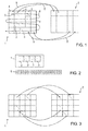
- Figures 1 to 3 illustrate processing of input data.
- Figure 1 illustrates an individual frame 1 included in the received input data.
- the input data may originally be included in packets, for instance.
- the individual frame 1 is divided into data blocks of a suitable size.
- the block may include data in one dimension, two dimensions or more than two dimensions. In case of an image of a video, each block may include 8x8 pixels, for instance.
- the individual frame 1 has been divided into 20 blocks.
- the input data may include video data, audio data, images, graphics data, text data, ECG data, seismic data, ASCII data, Unicode data, binary data or financial data, for instance.
- the blocks of the individual frame 1 which is being processed are compared to corresponding blocks of a first prediction frame 2, as illustrated by arrows 5.
- the first prediction frame 2 represents the content of the previously processed individual frame.
- the prediction frame 2 may represent the previous image in the video (or an entirely black or other predefined or delivered color valued frame) when a first individual frame or alternatively an Intra frame or key frame of input data is being processed and the comparison will indicate what parts (blocks) of the individual frame 1 have changed since the previous image in the video, for instance.
- the comparison may be based on colour values, luminance, or intensity, for instance.
- thresholds in determining whether or not a block is identified as changed, such that a change in one single pixel is not necessarily determined to be an indication of a changed frame, but instead a sufficient number of pixels must have changed, for instance, in order to determine that the threshold is passed and the block is identified as changed.
- a threshold may be utilized in some implementations, in order to ensure that only detected differences which are significant enough trigger detection of a changed block.
- RD-optimization Rate-Distortion Optimization
- the calculated RD-value of the unchanged block is then compared with the RD-value calculated by using some coding method for coding the block.
- Reconstruction error can be e.g. sum of absolute differences (SAD), sum of square differences (SSD), mean absolute error (MAE), mean square error (MSE), maximum absolute difference (MaxAD), but not limited thereto.
- the comparison is carried out by comparing each block of the individual frame 1 with the corresponding block in the prediction frame 2.
- the blocks of the individual frame 1 may be processed in the order illustrated by arrow 6, for instance.
- intermediate data 7 and a change indicator 8 illustrated in Figure 2 are generated.
- the block in the upper left corner of the individual frame 1 does correspond to the block in the upper left corner of the prediction frame 2, therefore this block is identified as unchanged.
- This unchanged block 4 is dropped by not including it into the intermediate data 7.
- the change indicator 8 is, however, generated to indicate the first processed block of frame 1 as unchanged with a "0" (most to the left in Figure 2 ).
- the second block from left in the upper row of the frame 1 is assumed to not correspond to the second block from left in the upper row of the prediction frame 2. Therefore this block is identified as a changed block.
- the changed block 3 is included in the intermediate data 7 and the change indicator 8 is generated to indicate the second processed block of frame 1 as changed with a "1".
- the processing continues for all blocks of frame 1 as explained above, resulting in the intermediate data 7 and change indicator 8 illustrated in Figure 2 for the first processed individual frame 1 illustrated in Figure 1 .
- the intermediate data 7 includes for the first processed individual frame 1 only the image data of four changed blocks 3, and the change indicator 8 for this processed frame 1 indicates in the order that the frame has been processed with a "1" locations of changed blocks 3 and with a "0" locations of (dropped) unchanged blocks 4.
- the intermediate data 7 and the change indicator 8 for the first block is stored or forwarded for further processing.
- the prediction frame 2 is modified, if necessary.
- the modification may be carried out such that the pixels of the blocks of the first processed individual frame 1 that have been identified as changed blocks 3 are copied into the corresponding locations of the first prediction frame 2, as illustrated in Figure 3 .
- the first prediction frame is again modified (if necessary), and the process continues until all individual frames of the received input data have been processed in the same way.
- the video or scene will change dramatically between two video frames, or an intra frame or a key-frame is required for the frame.
- it is possible to deliver separate global change information e.g. global motion information, scale, multiplier, or addition/subtraction value for reference frame
- the reference frame is initialized (and optional initialization values) from the processor to the reproduction device, which uses it as the second prediction frame when intermediate data is processed by the reproducer.
- the processor and the reproducer can operate similarly and guarantee successful operation (similar frames are used in prediction and reconstruction).
- Figure 4 illustrates reproduction based on the intermediate data and the change indicator produced in the processing of Figures 1 to 3 .
- a second prediction frame 9 is modified by utilizing the intermediate data 7 containing the changed blocks 3 and the change indicator 8 produced during processing of the first individual frame 1 of the input data according to Figures 1 to 3 .
- the blocks of the second prediction frame 9 are processed in the same order as in Figure 1 , as illustrated by arrow 6.
- the changed blocks 3 included in the received intermediate data 7 are obtained one by one, and the received change indicator is used to determine at which positions the changed blocks 3 should be used for modifying the data of the second prediction frame 9. For instance, the first "0" in the change indicator indicates that the upper left block of the second prediction frame 9 should not be modified, while the second "1" indicates that the second block from the left upper corner of the prediction frame 9 should be modified by using the content of the first changed block 3 of the intermediate data.
- output data is generated to include the content of the modified second prediction frame 9.
- processing of the intermediate data and the position indicator produced by processing of the second individual frame in Figures 1 to 3 is started.
- the second prediction frame 9 modified as explained above is used for further modification in the same way as explained above.
- output data is again generated to include the content of the newly modified second prediction frame 9.
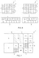
- Figure 5 illustrates a system with a processor and a reproducer.
- the processor and the reproducer may be configured to operate as has been explained in connection with Figures 1 to 4 .
- Figure 5 illustrates a processor 12 receiving input data 10 for processing, and a reproducer 13 which receives data from the processor 12, and which subsequently is capable of producing an output data 11 that with a sufficient accuracy corresponds to the input data 10.
- the processor 12 and the reproducer 13 may be implemented with circuitry, a combination of circuitry and software or as computer programs which are configured to control a programmable computer to carry out the tasks of the previous and the following explanation.
- each computer program may be contained on a non-transitory computer storage medium which can be read by a computer.
- the processor 12 comprises a comparator 14, which receives the input data 10, divides one frame at a time into data blocks and carries out the comparison between the blocks of the processed individual frame 1 and the first prediction frame 2 (maintained in the memory 15), as explained in connection with Figure 1 . Based on the comparison the blocks detected as changed blocks 3 are included in the generated intermediate data 7 and the positions of the changed blocks 3 and the unchanged blocks are included in the change indicator 8. After processing of each individual frame, the first prediction frame 2 maintained in memory 15 is modified (if necessary) by a modification block 16, if necessary, as explained in connection with Figure 3 .
- the intermediate data 7 is forwarded to an encoder 17, directly or after storage in a memory (not illustrated).
- the encoder may be standard previously known image/video encoder, such as a DiVX, MPEG4, JPEG or JPE2000 encoder, for instance.
- Such an encoder 17 is capable of reducing the data size of the intermediate data considerably, as previously known.
- the fact that the unchanged blocks have already previously been dropped by the processor makes the encoding much more efficient as it is not necessary for the encoder 17 to process all the blocks of the original input data 10, but only the changed blocks 3.
- the amount of data which is transmitted (possibly stored in a memory before being transmitted) for subsequent use by a reproducer can be minimized.
- the encoded intermediate data is forwarded to a decoder 18, directly or after storage in a memory (not illustrated).
- the decoder 18 may be a standard previously known image/video decoder, for instance.
- the decoder restores the intermediate data 7 which is forwarded to the reproducer 13, directly or after storage in a memory (not illustrated).
- a modification block 19 utilizes the intermediate data 7 and the change indicator 8 to modify the second prediction frame 9 maintained in a memory 20, as explained in connection with Figure 4 .
- Output data 11 is produced by the reproducer by including the content of the second intermediate frame 9 into the output data 11. Consequently the output data 11 corresponds with sufficient accuracy to the input data 10, and the original video (for instance) may be displayed on a display, for instance.
- the size of the delivered frame to the encoder is similar than the size of the input frame, but in the encoder and in the decoder the data values of the blocks that are unchanged by change indicator are just ignored in the processing (encoding and decoding) and the data values of those blocks will be similar than the data values of the prediction frame.
- This enables minimizing the amount of processing, as well as the data delivery, in the encoder and in the decoder but the changed blocks can still be coded e.g. with motion estimation methods. This is possible due to the block positions being preserved and the prediction frame containing all the needed data values.
- the encoder 17 is integrated into the processor 12, and/or that the decoder 18 is integrated into the reproducer 13.
- the input data may in praxis be some other type of data than video.
- the input data is audio data, in which case the frames contain samples of audio signals, for instance.
- One frame may contain 200 samples, for instance.
- the comparison may be carried out by comparing the frequency and/or the intensity of the samples, for instance, in order to identify the changed blocks and the unchanged blocks of the processed individual frame.
- an encoder and decoder suitable for handling audio signals may be utilized.
- Still image encoding is that e.g. each row (or column) of data blocks is processed as one frame. This enables that still image contains also multiple frames and this kind of method enables prediction to utilize spatial information instead of the temporal information that is used in video frames, where the individual images are frames.
- Figure 6 illustrates a second embodiment for processing input data.
- the second embodiment corresponds to a great extent to the embodiment explained in connection with Figures 1 to 5 . Therefore the embodiment of Figure 6 will be explained mainly by pointing out the differences between these embodiments.
- the intermediate data 7' produced during processing of the first individual frame 1 (to the right in Figure 6 ) and the following individual frame 1 (to the left in Figure 6 ) includes a header 21 indicating the frame size.
- the headers 21 are shown to indicate the frame size in the form 4x1 and 6x1, where the numbers refer to the number of blocks (such as blocks with 8x8 pixels) included in the frame in the horizontal and vertical direction. This is, however, only an example.
- the frame size indicator may include information about the size of the blocks in addition to the number of blocks in the horizontal and vertical direction.
- the frame size may be indicated directly and only as the number of pixels in the horizontal and vertical direction of the entire frame, such as M x N pixels, for instance, in which case the number of blocks must not necessarily be indicated at all.
- Figure 7 illustrates a second embodiment for processing input data.
- the second embodiment corresponds to a great extend to the embodiments explained in connection with Figures 1 to 6 . Therefore the embodiment of Figure 7 will mainly be explained by pointing out the differences between these embodiments.
- the change indicator additionally indicates the size of the blocks of the processed individual frame.
- the individual frame 1 is at a first level divided into six blocks A, B, C, D, E, F with the same predefined size.
- each one of the six blocks may be split into four sub blocks, and each sub block may again be split into four sub blocks.
- the first prediction frame is divided into blocks in the same way. Thereby blocks of equal size may be compared to each other.
- the size indicator may include for each block a first indicator which is "0" if the block is not split into four sub blocks, and which is "1" if the block is split. In case the block is split into four sub blocks, four indicators follow that indicate whether or not the sub blocks are split in to four new sub blocks.
- the size indicator takes the form: 0 0 1 0000 0 1 0010 0000 1 1000 0000, where first two “0” illustrate that the initial blocks A and B are not split, third block C is split “1” but the four sub blocks are not split "0000", fourth block D is not split "0", fifth block E is split "1" in to four sub blocks, first two sub blocks (E1, E2) are not split but sub block E3 is split into four sub blocks and sub block E4 is not split "0010", etc.
- the reproducer 13 is capable of reproducing a frame corresponding with sufficient accuracy to the individual frame 1 illustrated in Figure 7 such that also the size of the blocks can be taken into account.
- the embodiment of Figure 7 may be used in combination with the embodiment of the previous embodiments, such that some of the frames of the input data are divided into blocks having a fixed standard size, and some of the blocks are divided into blocks of different size. In that case the size indicator needs to be included into the change indicator 8 only for the blocks which are not divided into the fixed standard size.
- the way of dividing the frames into blocks of different size explained in connection with Figure 7 is only an example, and in practice the frames may be divided into blocks of different size in some other way, in which case the size indicator which is included in the change indicator 8 indicates the block size in a different way.
- One alternative is to utilize initial blocks of smaller size, which are combined into larger blocks when appropriate.
- the processor and the reproducer can be used recursively. This means that the same frame of the input data can be processed with the processor multiple times and every time the frame is processed the quality of reconstructed image is increased. With recursive processing it is possible to deliver every round all the change indication values or it is possible that in the next round only those values are delivered that were changed in the previous indication values.
- Such a solution may be implemented such that in a first round a frame of the input data is processed with the processor, intermediate data and the change indicator is forwarded to the reproducer and the first prediction frame is updated. In a second round the same frame of the input data is again processed, but now by using the updated first prediction frame.
- Figure 8 illustrates a second embodiment of a system with a processor and a reproducer.
- the embodiment of Figure 8 is very similar as the embodiment explained in connection with Figure 5 . Therefore the embodiment of Figure 8 will be explained mainly by pointing out the differences between these embodiments.
- a processor 12' with an integrated encoder 17 is utilized.
- the reproducer 13' comprises an integrated decoder. Therefore only two components are needed for processing the input data 10 and for reproducing the output data 11.
- Figure 9 illustrates a third embodiment of a system with a processor and a reproducer.
- the embodiment of Figure 9 is very similar to the embodiment of Figure 5 . Therefore the embodiment of Figure 9 will mainly be explained by pointing out the differences between the embodiment of Figure 5 and the embodiment of Figure 9 .
- the encoder 17 is a standard previously known encoder.
- the encoder 17" is not a standard encoder, but instead it is capable of receiving and handling the change indicator 8. Consequently, it is not necessary to drop the unchanged blocks 4 at the processor 12".
- the intermediate data 7" may include both the changed blocks 3 and the unchanged blocks 4.
- the encoder 17" is capable of selecting the correct blocks, in other words the changed blocks 3 only, for encoding.
- the encoding is carried out similarly as in the previous embodiments and the decoder 18 and the reproducer 13 therefore corresponds to the decoder and reproducer of the previous embodiment. Consequently dropping of unchanged blocks 4 is carried out by the encoder 17".
- the amount of data transmitted between the encoder 17" and the decoder 18 can therefore be minimized.
- Figure 9 also illustrates with dashed lines that the first prediction frame 2 is modified by taking into account encoding and decoding operations carried out for the changed movement blocks 3 contained in the intermediate data 7". In this way it can be ensured that possible modifications occurring due to the encoding and decoding operations can be accurately taken into account for the first prediction frame 2.
- first prediction frame 2 always corresponds as much as possible to the second prediction frame 9, which results in better quality.
- encoder 17" is integrated into the processor the encoder and the processor may utilize the same single first prediction frame in their operations.
Landscapes
- Engineering & Computer Science (AREA)
- Multimedia (AREA)
- Signal Processing (AREA)
- Compression Or Coding Systems Of Tv Signals (AREA)
- Compression, Expansion, Code Conversion, And Decoders (AREA)
- Compression Of Band Width Or Redundancy In Fax (AREA)
Priority Applications (1)
| Application Number | Priority Date | Filing Date | Title |
|---|---|---|---|
| EP16192195.2A EP3133815A1 (fr) | 2013-06-17 | 2013-06-17 | Systeme et procede de traitement de trames |
Applications Claiming Priority (2)
| Application Number | Priority Date | Filing Date | Title |
|---|---|---|---|
| EP16192195.2A EP3133815A1 (fr) | 2013-06-17 | 2013-06-17 | Systeme et procede de traitement de trames |
| EP20130172237 EP2816807A1 (fr) | 2013-06-17 | 2013-06-17 | Traitement et reproduction d'images |
Related Parent Applications (1)
| Application Number | Title | Priority Date | Filing Date |
|---|---|---|---|
| EP20130172237 Division EP2816807A1 (fr) | 2004-08-12 | 2013-06-17 | Traitement et reproduction d'images |
Publications (1)
| Publication Number | Publication Date |
|---|---|
| EP3133815A1 true EP3133815A1 (fr) | 2017-02-22 |
Family
ID=48625906
Family Applications (2)
| Application Number | Title | Priority Date | Filing Date |
|---|---|---|---|
| EP16192195.2A Withdrawn EP3133815A1 (fr) | 2013-06-17 | 2013-06-17 | Systeme et procede de traitement de trames |
| EP20130172237 Ceased EP2816807A1 (fr) | 2004-08-12 | 2013-06-17 | Traitement et reproduction d'images |
Family Applications After (1)
| Application Number | Title | Priority Date | Filing Date |
|---|---|---|---|
| EP20130172237 Ceased EP2816807A1 (fr) | 2004-08-12 | 2013-06-17 | Traitement et reproduction d'images |
Country Status (4)
| Country | Link |
|---|---|
| EP (2) | EP3133815A1 (fr) |
| JP (1) | JP6363181B2 (fr) |
| CN (1) | CN105474644B (fr) |
| WO (1) | WO2014202830A1 (fr) |
Families Citing this family (4)
| Publication number | Priority date | Publication date | Assignee | Title |
|---|---|---|---|---|
| JP6261020B2 (ja) * | 2016-06-28 | 2018-01-17 | 株式会社Nexpoint | 画面画像転送方法及び画面画像復元方法 |
| JP6284172B1 (ja) * | 2017-12-06 | 2018-02-28 | 株式会社Nexpoint | 画面画像転送方法、画像復元方法、画面画像転送システム、画像復元システム、画面画像転送プログラム、画像復元プログラム、画像圧縮方法、画像圧縮システム、画像圧縮プログラム |
| CN112218087B (zh) * | 2020-11-27 | 2021-05-04 | 浙江智慧视频安防创新中心有限公司 | 图像编码和解码方法、编码和解码装置、编码器及解码器 |
| CN113379583A (zh) * | 2021-05-31 | 2021-09-10 | 北京达佳互联信息技术有限公司 | 图像签名方法、装置、计算设备及存储介质 |
Citations (3)
| Publication number | Priority date | Publication date | Assignee | Title |
|---|---|---|---|---|
| EP0518464A2 (fr) * | 1991-06-14 | 1992-12-16 | Tektronix Inc. | Compression/décompression spatio-temporelle adaptive de signaux d'image vidéo |
| WO2006016007A1 (fr) | 2004-08-12 | 2006-02-16 | Gurulogic Microsystems Oy | Traitement d'une image video |
| US20120219065A1 (en) * | 2004-08-12 | 2012-08-30 | Gurulogic Microsystems Oy | Processing of image |
Family Cites Families (14)
| Publication number | Priority date | Publication date | Assignee | Title |
|---|---|---|---|---|
| FI70662C (fi) * | 1984-12-14 | 1986-09-24 | Valtion Teknillinen | Videokomprimeringsfoerfarande |
| JPH05284368A (ja) * | 1992-03-31 | 1993-10-29 | Fujitsu Ltd | 画像データ符号化・復元方法及びその装置 |
| JPH05284369A (ja) * | 1992-03-31 | 1993-10-29 | Fujitsu Ltd | 画像データ符号化・復元方法及びその装置 |
| JPH06153180A (ja) * | 1992-09-16 | 1994-05-31 | Fujitsu Ltd | 画像データ符号化方法及び装置 |
| JPH06105303A (ja) * | 1992-09-21 | 1994-04-15 | Fujitsu Ltd | 画像データ符号化方法及び装置 |
| JPH06217273A (ja) * | 1993-01-13 | 1994-08-05 | Fujitsu Ltd | 画像データ符号化方法および装置 |
| JPH0795565A (ja) * | 1993-09-21 | 1995-04-07 | Fujitsu Ltd | 画像データ復元装置および方法 |
| JPH07131787A (ja) * | 1993-11-05 | 1995-05-19 | Fujitsu Ltd | 画像データ符号化方法および装置 |
| JPH07231445A (ja) * | 1994-02-18 | 1995-08-29 | Hitachi Ltd | 画像符号化方法およびその装置 |
| JPH07298060A (ja) * | 1994-04-22 | 1995-11-10 | Fujitsu Ltd | 画像データ符号化方法及び装置ならびに画像データ復元方法及び装置 |
| EP1604628A3 (fr) * | 2004-06-11 | 2006-07-19 | Hill-Rom Services, Inc. | Lit de soin pour le traitement des maladies pulmonaires et des escarres nosocomiaux |
| US8638337B2 (en) * | 2009-03-16 | 2014-01-28 | Microsoft Corporation | Image frame buffer management |
| US9363535B2 (en) * | 2011-07-22 | 2016-06-07 | Qualcomm Incorporated | Coding motion depth maps with depth range variation |
| CN103002284B (zh) * | 2012-11-20 | 2016-06-08 | 北京大学 | 一种基于场景模型自适应更新的视频编解码方法 |
-
2013
- 2013-06-17 EP EP16192195.2A patent/EP3133815A1/fr not_active Withdrawn
- 2013-06-17 EP EP20130172237 patent/EP2816807A1/fr not_active Ceased
-
2014
- 2014-06-16 JP JP2016518555A patent/JP6363181B2/ja active Active
- 2014-06-16 CN CN201480045657.8A patent/CN105474644B/zh active Active
- 2014-06-16 WO PCT/FI2014/050479 patent/WO2014202830A1/fr active Application Filing
Patent Citations (3)
| Publication number | Priority date | Publication date | Assignee | Title |
|---|---|---|---|---|
| EP0518464A2 (fr) * | 1991-06-14 | 1992-12-16 | Tektronix Inc. | Compression/décompression spatio-temporelle adaptive de signaux d'image vidéo |
| WO2006016007A1 (fr) | 2004-08-12 | 2006-02-16 | Gurulogic Microsystems Oy | Traitement d'une image video |
| US20120219065A1 (en) * | 2004-08-12 | 2012-08-30 | Gurulogic Microsystems Oy | Processing of image |
Non-Patent Citations (1)
| Title |
|---|
| DAVID N HEIN ET AL: "Video Compression Using Conditional Replenishment and Motion Prediction", IEEE TRANSACTIONS ON ELECTROMAGNETIC COMPATIBILITY, IEEE SERVICE CENTER, NEW YORK, NY, US, vol. EMC-10, no. 3, 1 August 1984 (1984-08-01), pages 134 - 142, XP011165174, ISSN: 0018-9375 * |
Also Published As
| Publication number | Publication date |
|---|---|
| CN105474644B (zh) | 2019-11-05 |
| WO2014202830A1 (fr) | 2014-12-24 |
| EP2816807A1 (fr) | 2014-12-24 |
| JP6363181B2 (ja) | 2018-07-25 |
| CN105474644A (zh) | 2016-04-06 |
| JP2016530750A (ja) | 2016-09-29 |
Similar Documents
| Publication | Publication Date | Title |
|---|---|---|
| KR102492838B1 (ko) | 더 높은 계층과 더 낮은 층 사이의 차이를 이용한 비디오 압축 | |
| KR102336179B1 (ko) | 비디오 데이터 처리 시스템 | |
| US9509991B2 (en) | Processing and reproduction of frames | |
| US9503751B2 (en) | Method and apparatus for simplified depth coding with extended prediction modes | |
| EP3133815A1 (fr) | Systeme et procede de traitement de trames | |
| US20190289329A1 (en) | Apparatus and a method for 3d video coding | |
| US20230370600A1 (en) | A method and apparatus for encoding and decoding one or more views of a scene | |
| CN113228663A (zh) | 用于可伸缩图像编码的方法、设备、计算机程序和计算机可读介质 | |
| US11363286B2 (en) | System and method for improved video operations | |
| KR20220061032A (ko) | 비디오 프로세싱을 위한 방법 및 이미지 프로세싱 디바이스 | |
| JP2016103808A (ja) | 画像処理装置、画像処理方法及びプログラム | |
| EP2661081B1 (fr) | Traitement d'image | |
| JP3176601B1 (ja) | 画像復号化装置 | |
| WO2024073066A1 (fr) | Codage de région d'intérêt pour vcm | |
| CN116934647A (zh) | 基于空间角度可变形卷积网络的压缩光场质量增强方法 | |
| CN117376606A (zh) | 视频补帧方法、装置、电子设备及存储介质 | |
| KR20230079184A (ko) | 몰입형 비디오의 인코딩 및 디코딩 | |
| CN116055749A (zh) | 视频处理方法及装置 | |
| CN115866254A (zh) | 一种传输视频帧及摄像参数信息的方法与设备 |
Legal Events
| Date | Code | Title | Description |
|---|---|---|---|
| PUAI | Public reference made under article 153(3) epc to a published international application that has entered the european phase |
Free format text: ORIGINAL CODE: 0009012 |
|
| AC | Divisional application: reference to earlier application |
Ref document number: 2816807 Country of ref document: EP Kind code of ref document: P |
|
| AK | Designated contracting states |
Kind code of ref document: A1 Designated state(s): AL AT BE BG CH CY CZ DE DK EE ES FI FR GB GR HR HU IE IS IT LI LT LU LV MC MK MT NL NO PL PT RO RS SE SI SK SM TR |
|
| STAA | Information on the status of an ep patent application or granted ep patent |
Free format text: STATUS: THE APPLICATION IS DEEMED TO BE WITHDRAWN |
|
| 18D | Application deemed to be withdrawn |
Effective date: 20170823 |