EP3133364A1 - Heat spreading module for portable electronic device - Google Patents
Heat spreading module for portable electronic device Download PDFInfo
- Publication number
- EP3133364A1 EP3133364A1 EP16184449.3A EP16184449A EP3133364A1 EP 3133364 A1 EP3133364 A1 EP 3133364A1 EP 16184449 A EP16184449 A EP 16184449A EP 3133364 A1 EP3133364 A1 EP 3133364A1
- Authority
- EP
- European Patent Office
- Prior art keywords
- heat
- metal plate
- heated
- heating element
- heat pipe
- Prior art date
- Legal status (The legal status is an assumption and is not a legal conclusion. Google has not performed a legal analysis and makes no representation as to the accuracy of the status listed.)
- Granted
Links
Images



Classifications
-
- H—ELECTRICITY
- H05—ELECTRIC TECHNIQUES NOT OTHERWISE PROVIDED FOR
- H05K—PRINTED CIRCUITS; CASINGS OR CONSTRUCTIONAL DETAILS OF ELECTRIC APPARATUS; MANUFACTURE OF ASSEMBLAGES OF ELECTRICAL COMPONENTS
- H05K7/00—Constructional details common to different types of electric apparatus
- H05K7/20—Modifications to facilitate cooling, ventilating, or heating
- H05K7/2029—Modifications to facilitate cooling, ventilating, or heating using a liquid coolant with phase change in electronic enclosures
- H05K7/20336—Heat pipes, e.g. wicks or capillary pumps
-
- F—MECHANICAL ENGINEERING; LIGHTING; HEATING; WEAPONS; BLASTING
- F28—HEAT EXCHANGE IN GENERAL
- F28D—HEAT-EXCHANGE APPARATUS, NOT PROVIDED FOR IN ANOTHER SUBCLASS, IN WHICH THE HEAT-EXCHANGE MEDIA DO NOT COME INTO DIRECT CONTACT
- F28D15/00—Heat-exchange apparatus with the intermediate heat-transfer medium in closed tubes passing into or through the conduit walls ; Heat-exchange apparatus employing intermediate heat-transfer medium or bodies
- F28D15/02—Heat-exchange apparatus with the intermediate heat-transfer medium in closed tubes passing into or through the conduit walls ; Heat-exchange apparatus employing intermediate heat-transfer medium or bodies in which the medium condenses and evaporates, e.g. heat pipes
- F28D15/04—Heat-exchange apparatus with the intermediate heat-transfer medium in closed tubes passing into or through the conduit walls ; Heat-exchange apparatus employing intermediate heat-transfer medium or bodies in which the medium condenses and evaporates, e.g. heat pipes with tubes having a capillary structure
-
- F—MECHANICAL ENGINEERING; LIGHTING; HEATING; WEAPONS; BLASTING
- F28—HEAT EXCHANGE IN GENERAL
- F28D—HEAT-EXCHANGE APPARATUS, NOT PROVIDED FOR IN ANOTHER SUBCLASS, IN WHICH THE HEAT-EXCHANGE MEDIA DO NOT COME INTO DIRECT CONTACT
- F28D15/00—Heat-exchange apparatus with the intermediate heat-transfer medium in closed tubes passing into or through the conduit walls ; Heat-exchange apparatus employing intermediate heat-transfer medium or bodies
- F28D15/02—Heat-exchange apparatus with the intermediate heat-transfer medium in closed tubes passing into or through the conduit walls ; Heat-exchange apparatus employing intermediate heat-transfer medium or bodies in which the medium condenses and evaporates, e.g. heat pipes
- F28D15/0233—Heat-exchange apparatus with the intermediate heat-transfer medium in closed tubes passing into or through the conduit walls ; Heat-exchange apparatus employing intermediate heat-transfer medium or bodies in which the medium condenses and evaporates, e.g. heat pipes the conduits having a particular shape, e.g. non-circular cross-section, annular
-
- F—MECHANICAL ENGINEERING; LIGHTING; HEATING; WEAPONS; BLASTING
- F28—HEAT EXCHANGE IN GENERAL
- F28D—HEAT-EXCHANGE APPARATUS, NOT PROVIDED FOR IN ANOTHER SUBCLASS, IN WHICH THE HEAT-EXCHANGE MEDIA DO NOT COME INTO DIRECT CONTACT
- F28D15/00—Heat-exchange apparatus with the intermediate heat-transfer medium in closed tubes passing into or through the conduit walls ; Heat-exchange apparatus employing intermediate heat-transfer medium or bodies
- F28D15/02—Heat-exchange apparatus with the intermediate heat-transfer medium in closed tubes passing into or through the conduit walls ; Heat-exchange apparatus employing intermediate heat-transfer medium or bodies in which the medium condenses and evaporates, e.g. heat pipes
- F28D15/0275—Arrangements for coupling heat-pipes together or with other structures, e.g. with base blocks; Heat pipe cores
-
- G—PHYSICS
- G06—COMPUTING OR CALCULATING; COUNTING
- G06F—ELECTRIC DIGITAL DATA PROCESSING
- G06F1/00—Details not covered by groups G06F3/00 - G06F13/00 and G06F21/00
- G06F1/16—Constructional details or arrangements
- G06F1/20—Cooling means
- G06F1/203—Cooling means for portable computers, e.g. for laptops
-
- H—ELECTRICITY
- H04—ELECTRIC COMMUNICATION TECHNIQUE
- H04M—TELEPHONIC COMMUNICATION
- H04M1/00—Substation equipment, e.g. for use by subscribers
- H04M1/02—Constructional features of telephone sets
- H04M1/0202—Portable telephone sets, e.g. cordless phones, mobile phones or bar type handsets
-
- H—ELECTRICITY
- H05—ELECTRIC TECHNIQUES NOT OTHERWISE PROVIDED FOR
- H05K—PRINTED CIRCUITS; CASINGS OR CONSTRUCTIONAL DETAILS OF ELECTRIC APPARATUS; MANUFACTURE OF ASSEMBLAGES OF ELECTRICAL COMPONENTS
- H05K7/00—Constructional details common to different types of electric apparatus
- H05K7/20—Modifications to facilitate cooling, ventilating, or heating
- H05K7/2039—Modifications to facilitate cooling, ventilating, or heating characterised by the heat transfer by conduction from the heat generating element to a dissipating body
-
- H—ELECTRICITY
- H05—ELECTRIC TECHNIQUES NOT OTHERWISE PROVIDED FOR
- H05K—PRINTED CIRCUITS; CASINGS OR CONSTRUCTIONAL DETAILS OF ELECTRIC APPARATUS; MANUFACTURE OF ASSEMBLAGES OF ELECTRICAL COMPONENTS
- H05K7/00—Constructional details common to different types of electric apparatus
- H05K7/20—Modifications to facilitate cooling, ventilating, or heating
- H05K7/2039—Modifications to facilitate cooling, ventilating, or heating characterised by the heat transfer by conduction from the heat generating element to a dissipating body
- H05K7/20509—Multiple-component heat spreaders; Multi-component heat-conducting support plates; Multi-component non-closed heat-conducting structures
-
- H—ELECTRICITY
- H10—SEMICONDUCTOR DEVICES; ELECTRIC SOLID-STATE DEVICES NOT OTHERWISE PROVIDED FOR
- H10W—GENERIC PACKAGES, INTERCONNECTIONS, CONNECTORS OR OTHER CONSTRUCTIONAL DETAILS OF DEVICES COVERED BY CLASS H10
- H10W40/00—Arrangements for thermal protection or thermal control
- H10W40/70—Fillings or auxiliary members in containers or in encapsulations for thermal protection or control
- H10W40/73—Fillings or auxiliary members in containers or in encapsulations for thermal protection or control for cooling by change of state
-
- F—MECHANICAL ENGINEERING; LIGHTING; HEATING; WEAPONS; BLASTING
- F28—HEAT EXCHANGE IN GENERAL
- F28F—DETAILS OF HEAT-EXCHANGE AND HEAT-TRANSFER APPARATUS, OF GENERAL APPLICATION
- F28F13/00—Arrangements for modifying heat-transfer, e.g. increasing, decreasing
- F28F2013/005—Thermal joints
- F28F2013/006—Heat conductive materials
Definitions
- the present invention relates to a heat spreading module that is used for a portable electronic device such as a multifunctional mobile phone (smartphone) and a tablet personal computer.
- a portable electronic device such as a multifunctional mobile phone (smartphone) and a tablet personal computer.
- a portable information terminal configured to transfer heat of a heating element to a low temperature portion by a heat pipe is described in Japanese Unexamined Patent Application, First Publication No. 2014-165596 A .
- the heat pipe is configured such that a copper tube is sealed at both ends thereof and a working fluid is contained inside the copper tube.
- a central portion of the heat pipe is arranged on an upper surface of the heating element, that is, a CPU, and both end sides extend to a battery side along a side portion of a casing.
- the central portion of the heat pipe arranged on the CPU is a flattened portion processed flatly due to a restriction on the space such as a reduction in the thickness of the casing.
- the CPU mounted on a substrate (motherboard) has a greater height than other elements.
- the flattened portion of the heat pipe is arranged on the CPU as described in Japanese Unexamined Patent Application, First Publication No. 2014-165596 A , therefore, the information terminal can be thinned.
- almost all of the heat of the CPU is transferred to the heat pipe, and the heat pipe transfers that heat.
- the heat pipe thus requires a large heat transfer capacity, and there is no other choice but to use the heat pipe having a large size or a large diameter. Accordingly, the information terminal is increased in size or thickness.
- the present invention has been made in view of the circumstances described above, and provides a heat spreading module capable of achieving both the reduction in the thickness of a portable electronic device and the increase in the cooling capability.
- a first aspect of the present invention is a heat spreading module for a portable electronic device configured such that a heat pipe is attached along a metal plate with which a heating element is brought into close contact, and heat of a heated region of the metal plate with which the heating element is brought into close contact is transferred to a place on the metal plate apart from the heated region by the heat pipe, wherein the heat pipe is configured such that a container is formed of a pipe made of metal, a portion of the container arranged on the heated region serves as a heated part, and a portion of the container apart from the heated region serves as a heat dissipation portion that dissipates heat to the metal plate, the heated portion is formed in a flat shape in such a manner that the container is squashed, and the heat dissipation portion is formed to be thicker than the heated portion having the flat shape, the metal plate has a hole portion having a predetermined length formed in a portion corresponding to the heated region, the heated portion having the flat shape is arranged inside the hole portion, and the heat dis
- a heat transfer material may be provided on the heated region so as to come into contact with a surface of the heated portion formed in the flat shape and so as to close the hole portion, and the heating element comes into contact with the heat transfer material so as to be capable of transferring heat.
- heat of the heating element is transferred to the heated portion of the heat pipe and the metal plate in the heated region.
- the heated portion of the heat pipe is formed in the flat shape and arranged inside the hole portion formed in the metal plate.
- the metal plate is not interposed between the heating element and the heated portion of the heat pipe. Therefore, the heat spreading module or a portable electronic device using the heat dissipation plate can be thinned.
- heat of the heating element is transferred not only to the heated portion of the heat pipe but also to the metal plate. Therefore, the amount of heat input to the heated portion of the heat pipe is moderated, whereby dry-out hardly occurs even though the heated portion is formed in the flat shape, and the heat dissipation performance or the cooling performance for the heating element is not deteriorated.
- the heat dissipation portion of the heat pipe is thicker than the heated portion, whereby vapor of a working fluid flows smoothly. Furthermore, the heat dissipation portion is brought into close contact with the metal plate. Therefore, the heat pipe has the excellent heat transfer performance, and moreover, the excellent heat dissipation performance.
- a heat dissipation plate (heat spreading module) 1 is incorporated in a portable electronic device such as a smartphone and a tablet personal computer (PC).
- the heat dissipation plate 1 dissipates heat of a heating element such as a CPU and reduces or suppresses a peak temperature of the heating element.
- An example of the heat dissipation plate 1 is illustrated in FIG. 1 .
- the heat dissipation plate 1 mainly includes a metal plate 2 in order to enlarge a dissipation region.
- a heat pipe 3 is attached to the metal plate 2.
- the heat pipe 3 is a known heat transferring element that transfers heat by a working fluid contained inside a container.
- the heat pipe 3 is configured such that a copper pipe is used as the container, water as the working fluid is contained inside the container, and an ultrafine wire such as a thin copper wire and a metal sintered compact having a porous structure or the like are accommodated as a wick inside the container.
- the heat pipe 3 is formed in a flat shape.
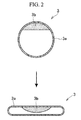
- the heat pipe 3 can be manufactured, for example, as illustrated in FIG. 2 .
- a copper pipe having a circular cross section is prepared as a container 3a, and a wick 3b is arranged inside the container 3a and fixed by sintering or the like.
- a working fluid is then injected into the container 3a, air is expelled, and the container 3a is closed tightly in this state.
- the container 3a is processed to be bent into a predetermined shape, and a load is applied in a radial direction to squash the container 3a, whereby the container 3a is molded into a flat shape.
- a portion having a predetermined length on one end side of the heat pipe 3 is a heated portion 4 where the working fluid evaporates due to heat input from the outside.
- a portion on the other end side is a heat dissipation portion 5 that dissipates heat to the outside.
- the heated portion 4 is squashed so as to be thinner than the heat dissipation portion 5.
- the heated portion 4 has a thickness of about 0.4 mm.
- the heat dissipation portion 5 is molded into a flat shape having a thickness of about 0.85 mm. Therefore, internal volume per unit length is small in the heated portion 4 and large in the heat dissipation portion 5.
- the metal plate 2 has a shape conforming to a shape of an electronic device to be used.
- the metal plate 2 has a substantially rectangular shape.
- a substantially central portion on one end side in a longitudinal direction of the metal plate 2 is a heated region 7 that receives heat from a heating element 6 such as a CPU.
- a hole portion 8 is formed in the heated region 7.
- the hole portion 8 is a so-called elongated hole having a width wider than that of the aforementioned heated portion 4 and narrower than that of the heated region 7.
- the heated portion 4 is fit into the hole portion 8.
- the heated portion 4 fit into the hole portion 8 is illustrated in FIG. 3 using a cross-sectional view.
- the heated portion 4 is fit into the hole portion 8 while a lower surface in FIG. 3 substantially coincides with a lower surface of the metal plate 2.
- a gap between an inner surface (or inner edge) of the hole portion 8 and the heated portion 4 is filled with an appropriate fixing material (for example, solder) 9, whereby the heated portion 4 is fixed to the metal plate 2.
- the thickness of the heated portion 4 is thicker than that of the metal plate 2 even though the heated portion 4 is formed in a flat shape as described above.
- An upper portion of the heated portion 4 in FIG. 3 therefore, projects upward from an upper surface of the metal plate 2.
- the metal plate 2 is not interposed between the heated portion 4 (heat pipe 3) and the heating element 6. Accordingly, a height H at a place where the heating element 6 is provided (for example, dimension from the lower surface of the heated portion 4 (lower surface of the metal plate 2) to an upper surface of the heating element 6) is reduced by the thickness of the metal plate 2. In other words, the heat dissipation plate 1 itself is thinned. By using such heat dissipation plate 1, the portable electronic device can be reduced in thickness. Although a lower surface of the heating element 6 is in contact with an upper surface of the heated portion 4, the lower surface of the heating element 6 is apart from the upper surface of the metal plate 2. Therefore, a space between the lower surface of the heating element 6 and the upper surface of the metal plate 2 is filled with a thermal conductive material such as thermal grease Gth.
- a thermal conductive material such as thermal grease Gth.
- the heat pipe 3 is bent in a crank shape at a place where the heat pipe 3 is pulled out of the above-mentioned hole portion 8, whereby the heat pipe 3 extends along a surface (upper surface in FIGS. 1 and 3 ) of the metal plate 2.
- the heat pipe 3 is bent at a substantially right angle toward one side portion of the metal plate 2.
- the heat pipe 3 is further bent at a substantially right angle along the side portion of the metal plate 2.
- the purpose of bending the heat pipe 3 in such a manner is to avoid interference with components incorporated in the electronic device. Therefore, a bent shape of the heat pipe 3 may be a shape conforming to an inner structure of the electronic device.
- a portion of the heat pipe 3 directed to the side portion of the metal plate 2 and bent so as to extend along the side portion while the heat pipe 3 extends along the surface of the metal plate 2 in the above-mentioned manner is the heat dissipation portion 5.
- a cross-sectional shape of a portion 5a of the heat dissipation portion 5 extending from the above-mentioned heated portion 4 toward the side portion of the metal plate 2 is illustrated in FIG. 4 .
- a cross-sectional shape of a portion 5b of the heat dissipation portion 5 extending along the side portion of the metal plate 2 is illustrated in FIG. 5 .
- the portion 5a extending toward the side portion of the metal plate 2 is formed in a flat shape, but somewhat thicker than the heated portion 4.
- the portion 5b extending along the side portion of the metal plate 2 is formed in a flat shape, but much thicker than the heated portion 4.
- the purpose of forming the heat dissipation portion 5 so that the heat dissipation portion 5 is thicker than the heated portion 4 as described above is to increase the internal volume of the heat dissipation portion 5 in preparation for evaporation and an increase in volume of the working fluid.
- the heat dissipation portion 5 is brought into close contact with the metal plate 2 and fixed to the metal plate 2 by an appropriate manner such as using solder.
- the above-mentioned heat dissipation plate 1 is accommodated inside the portable electronic device such as a smartphone, whereby the heating element 6 such as a CPU is brought into contact with the heated region 7 so as to be capable of transferring heat.
- the heating element 6 such as a CPU is brought into contact with the heated region 7 so as to be capable of transferring heat.
- a width W 6 of the heating element 6 is greater than a width W 3 of the heated portion 4 of the heat pipe 3
- the heating element 6 comes into contact so as to be capable of transferring heat to both the heated portion 4 of the heat pipe 3 and the metal plate 2.
- a place on the metal plate 2 apart from the heated region 7 is brought into contact with or arranged on a portion having a low temperature such as a battery (not illustrated).
- Heat generated by the operation of the heating element 6 is transferred to the heat pipe 3 and the metal plate 2 in the heated region 7.
- the working fluid evaporates at the heated portion 4, and the vapor flows into the heat dissipation portion 5 having a low temperature and a low pressure.
- the working fluid then dissipates heat and condenses in the heat dissipation portion 5. Therefore, the heat transferred to the heat pipe 3 is transferred to the heat dissipation portion 5 in the form of latent heat of the working fluid, and the heat is dissipated from the heat dissipation portion 5 to the metal plate 2.
- the condensed working fluid flows back to the heated portion 4 by capillary force that occurs in the wick 3b and is heated again to evaporate, whereby the heat transfer is performed.
- the heat transferred from the heating element 6 to the metal plate 2 is conducted to a place on the metal plate 2 having a low temperature.
- heat of the heating element 6 is diffused to a place apart from the heating element 6 by the heat pipe 3 and the metal plate 2, and dissipated from the portion apart from the heating element 6 to the outside.
- the heating element 6 is cooled down and operation failure is prevented.
- heat of the heating element 6 is transferred to the heat pipe 3 and the metal plate 2 in the heated region 7, and dissipated by the heat pipe 3 and the metal plate 2, whereby the amount of heat input to the heat pipe 3 is suppressed. Therefore, even though the heated portion 4 of the heat pipe 3 is formed in a thin flat shape and the amount of working fluid retained in the heated portion 4 is limited, the occurrence of so-called dry-out, that is, a lack of the working fluid in the heated portion 4 that leads to a limitation on the heat transfer, can be avoided or suppressed.
- the heat dissipation portion 5 is formed to be thicker than the heated portion 4 and has the internal volume larger than that of the heated portion 4, the working fluid that has evaporated and increased its volume smoothly flows from the heated portion 4 into the heat dissipation portion 5, whereby the heat transfer by the heat pipe 3 can be sufficiently performed.
- the heat dissipation plate 1 of an embodiment of the present invention it is possible to achieve both the increase in the capability of the heat pipe 3 and the metal plate 2 to cool down the heating element 6 and the reduction in the thickness of the portable electronic device.
- FIG. 6 is a cross-sectional view illustrating another embodiment of the present invention, where the hole portion 8 in which the heated portion 4 is arranged is closed by a heat transfer material 10.
- the heat transfer material 10 is a plate material or a sheet material made of metal such as copper.
- the heat transfer material 10 is thinner than the metal plate 2.
- a central portion in a width direction of the heat transfer material 10 comes into close contact with a surface of the heated portion 4 (lower surface in FIG. 6 ). Both ends are pulled out of both sides of the heated portion 4 through the hole portion 8 to an upper surface side of the metal plate 2 in FIG. 6 and joined to the upper surface of the metal plate 2.
- the heat transfer material 10 is formed to have such a size that its contour is the same as a contour of the lower surface of the heating element 6, or such a size that its contour exceeds the contour of the lower surface of the heating element 6.
- the heating element 6 is arranged on the upper surface side in FIG. 6 and comes into direct contact with the heated portion 4 of the heat pipe 3 held by the heat transfer material 10.
- a space between the lower surface of the heating element 6 and an upper surface of the heat transfer material 10 is filled with a thermal conductive material such as thermal grease (omitted in FIG. 6 ). Heat of the heating element 6 is directly transferred to the heat pipe 3, transferred to the heat transfer material 10 through the thermal conductive material, and transferred to the metal plate 2 through the heat transfer material 10.
- a thermal conductive material such as thermal grease
- the heating element 6 can also be arranged on a lower surface side of the metal plate 2. In this case, heat of the heating element 6 is transferred to the heat pipe 3 through the heat transfer material 10, and heat is directly transferred from the heating element 6 to the metal plate 2. In any of these cases, a portion of the heat transferred from the heating element 6 to the metal plate 2 is transferred to the heat pipe 3 through the heat transfer material 10. Therefore, a lack of the heat dissipation by the metal plate 2 can be supplemented by the heat transfer by the heat pipe 3. Therefore, heat of the heating element 6 is efficiently dissipated by the heat transfer by the heat pipe 3 and the heat transmission by the metal plate 2, and an increase in the temperature around the heated region 7 is suppressed, whereby the heating element 6 can be effectively cooled down.
- a copper plate having a thickness of 0.2 mm was used as the metal plate.
- a heat pipe configured in such a manner that the wick made of a thin copper wire was arranged inside a copper pipe and water was contained as the working fluid was used as the heat pipe.
- the heated portion was processed flatly so as to have a thickness of 0.4 mm.
- the heat dissipation portion was processed into a flat shape having a thickness of 0.6 mm.
- the heated portion of the heat pipe was arranged inside the hole portion formed in the metal plate.
- the heated region therefore, has a maximum thickness of 0.4 mm in the heated portion.
- a heater As a substitute for the heating element, a heater, the output of which is adjustable, was brought into contact with the heated region.
- the temperature of the heated portion was measured when the output of the heater was set to 3W, 4W, and 5W. The result of the measurement of the temperature is illustrated in Table 1.
- Example 1 The metal plate and the heat pipe similar to those of Example 1 described above were used.
- the aforementioned heat transfer material illustrated in FIG. 6 was provided on the heated region, and the thickness of the heat transfer material was 0.05 mm. Accordingly, the thickness of the heated portion was set to 0.35 mm, whereby the heated region had a maximum thickness of 0.4 mm as was the case in Example 1.
- a heater as a substitute for the heating element, was brought into contact with the heated region. The temperature of the heated portion was measured when the output of the heater was set to 3W, 4W, and 5W. The result of the measurement of the temperature is illustrated in Table 1.
- Example 1 and Example 2 The metal plate and the heat pipe similar to those of Example 1 and Example 2 described above were used.
- the aforementioned hole portion was not provided in the heated region, and the heated portion of the heat pipe was directly brought into close contact with the metal plate.
- the heated portion was processed into a thin flat shape having a thickness of 0.2 mm so that the heated region had a maximum thickness of 0.4 mm.
- Other conditions were the same as those of Example 1 and Example 2 described above.
- a heater As a substitute for the heating element, a heater, the output of which is adjustable, was brought into contact with the heated region.
- the temperature of the heated portion was measured when the output of the heater was set to 3W, 4W, and 5W.
- Example 1 In any of Example 1, Example 2, and Comparative Example, the heated region has a maximum thickness of 0.4 mm and thus is reduced in thickness.
- the temperature of the heated portion is higher than those in Example 1 and Example 2, thermal resistance of the entire heat dissipation plate is large, and the cooling effect for the heating element is inferior.
- Example 1 and Example 2 revealed that thermal resistance of the heat dissipation plate is small enough for practical use, the heat transfer or the heat dissipation from the heated portion side to the heat dissipation portion side is enhanced, and the heating element can be effectively cooled down, whereby both the reduction in the thickness and the cooling performance can be achieved.
Landscapes
- Engineering & Computer Science (AREA)
- Physics & Mathematics (AREA)
- Thermal Sciences (AREA)
- General Engineering & Computer Science (AREA)
- Microelectronics & Electronic Packaging (AREA)
- Sustainable Development (AREA)
- Mechanical Engineering (AREA)
- Life Sciences & Earth Sciences (AREA)
- Theoretical Computer Science (AREA)
- Signal Processing (AREA)
- Computer Hardware Design (AREA)
- Human Computer Interaction (AREA)
- General Physics & Mathematics (AREA)
- Cooling Or The Like Of Semiconductors Or Solid State Devices (AREA)
- Cooling Or The Like Of Electrical Apparatus (AREA)
Abstract
Description
- The present invention relates to a heat spreading module that is used for a portable electronic device such as a multifunctional mobile phone (smartphone) and a tablet personal computer.
- A portable information terminal configured to transfer heat of a heating element to a low temperature portion by a heat pipe is described in Japanese Unexamined Patent Application, First Publication No.
2014-165596 A 2014-165596 A - In an electronic device such as the portable information terminal described in Japanese Unexamined Patent Application, First Publication No.
2014-165596 A 2014-165596 A 2014-165596 A - In addition to the large amount of heat input from the CPU to the heat pipe, since a heat input portion (or heated portion) that receives heat from the CPU is the flattened portion, the amount of working fluid retained in the heat input portion is small. When the amount of heat generation in the CPU is large, therefore, dry-out of the heat pipe is likely to occur, whereby capability to cool down the CPU might be limited.
- The present invention has been made in view of the circumstances described above, and provides a heat spreading module capable of achieving both the reduction in the thickness of a portable electronic device and the increase in the cooling capability.
- A first aspect of the present invention is a heat spreading module for a portable electronic device configured such that a heat pipe is attached along a metal plate with which a heating element is brought into close contact, and heat of a heated region of the metal plate with which the heating element is brought into close contact is transferred to a place on the metal plate apart from the heated region by the heat pipe, wherein the heat pipe is configured such that a container is formed of a pipe made of metal, a portion of the container arranged on the heated region serves as a heated part, and a portion of the container apart from the heated region serves as a heat dissipation portion that dissipates heat to the metal plate, the heated portion is formed in a flat shape in such a manner that the container is squashed, and the heat dissipation portion is formed to be thicker than the heated portion having the flat shape, the metal plate has a hole portion having a predetermined length formed in a portion corresponding to the heated region, the heated portion having the flat shape is arranged inside the hole portion, and the heat dissipation portion is brought into close contact with a surface of the place on the metal plate apart from the heated region, and in the heated region, heat is transferred from the heating element to the metal plate and the heated portion.
- In a second aspect of the present invention according to the heat spreading module for a portable electronic device of the above-mentioned first aspect, a heat transfer material may be provided on the heated region so as to come into contact with a surface of the heated portion formed in the flat shape and so as to close the hole portion, and the heating element comes into contact with the heat transfer material so as to be capable of transferring heat.
- According to the above-mentioned aspects of the present invention, heat of the heating element is transferred to the heated portion of the heat pipe and the metal plate in the heated region. The heated portion of the heat pipe is formed in the flat shape and arranged inside the hole portion formed in the metal plate. The metal plate is not interposed between the heating element and the heated portion of the heat pipe. Therefore, the heat spreading module or a portable electronic device using the heat dissipation plate can be thinned. According to the above-mentioned aspects of the present invention, heat of the heating element is transferred not only to the heated portion of the heat pipe but also to the metal plate. Therefore, the amount of heat input to the heated portion of the heat pipe is moderated, whereby dry-out hardly occurs even though the heated portion is formed in the flat shape, and the heat dissipation performance or the cooling performance for the heating element is not deteriorated.
- According to the above-mentioned aspects of the present invention, the heat dissipation portion of the heat pipe is thicker than the heated portion, whereby vapor of a working fluid flows smoothly. Furthermore, the heat dissipation portion is brought into close contact with the metal plate. Therefore, the heat pipe has the excellent heat transfer performance, and moreover, the excellent heat dissipation performance.
-
-
FIG. 1 is a perspective view schematically illustrating an example of the present invention. -
FIG. 2 is a cross-sectional view for describing a structure of a heat pipe. -
FIG. 3 is a cross-sectional view taken along line III-III ofFIG. 1 . -
FIG. 4 is a cross-sectional view taken along line IV-IV ofFIG. 1 . -
FIG. 5 is a cross-sectional view taken along line V-V ofFIG. 1 . -
FIG. 6 is a view for describing an example of a heat transfer material provided, which is a cross-sectional view drawn in the same way asFIG. 3 . - A heat dissipation plate (heat spreading module) 1 according to an embodiment of the present invention is incorporated in a portable electronic device such as a smartphone and a tablet personal computer (PC). The
heat dissipation plate 1 dissipates heat of a heating element such as a CPU and reduces or suppresses a peak temperature of the heating element. An example of theheat dissipation plate 1 is illustrated inFIG. 1 . Theheat dissipation plate 1 mainly includes ametal plate 2 in order to enlarge a dissipation region. Aheat pipe 3 is attached to themetal plate 2. - Since the
metal plate 2 is expected to have a high thermal conductivity and to be thin, a thin copper plate having a thickness of about 0.2 mm is employed as themetal plate 2. Theheat pipe 3 is a known heat transferring element that transfers heat by a working fluid contained inside a container. For example, theheat pipe 3 is configured such that a copper pipe is used as the container, water as the working fluid is contained inside the container, and an ultrafine wire such as a thin copper wire and a metal sintered compact having a porous structure or the like are accommodated as a wick inside the container. In the example illustrated inFIG. 1 , theheat pipe 3 is formed in a flat shape. - The
heat pipe 3 can be manufactured, for example, as illustrated inFIG. 2 . A copper pipe having a circular cross section is prepared as acontainer 3a, and awick 3b is arranged inside thecontainer 3a and fixed by sintering or the like. A working fluid is then injected into thecontainer 3a, air is expelled, and thecontainer 3a is closed tightly in this state. After that, thecontainer 3a is processed to be bent into a predetermined shape, and a load is applied in a radial direction to squash thecontainer 3a, whereby thecontainer 3a is molded into a flat shape. - A portion having a predetermined length on one end side of the
heat pipe 3 is a heatedportion 4 where the working fluid evaporates due to heat input from the outside. A portion on the other end side is aheat dissipation portion 5 that dissipates heat to the outside. The heatedportion 4 is squashed so as to be thinner than theheat dissipation portion 5. For example, the heatedportion 4 has a thickness of about 0.4 mm. Theheat dissipation portion 5 is molded into a flat shape having a thickness of about 0.85 mm. Therefore, internal volume per unit length is small in theheated portion 4 and large in theheat dissipation portion 5. - The
metal plate 2 has a shape conforming to a shape of an electronic device to be used. In the example illustrated inFIG. 1 , themetal plate 2 has a substantially rectangular shape. A substantially central portion on one end side in a longitudinal direction of themetal plate 2 is aheated region 7 that receives heat from aheating element 6 such as a CPU. Ahole portion 8 is formed in theheated region 7. Thehole portion 8 is a so-called elongated hole having a width wider than that of the aforementioned heatedportion 4 and narrower than that of theheated region 7. The heatedportion 4 is fit into thehole portion 8. - The heated
portion 4 fit into thehole portion 8 is illustrated inFIG. 3 using a cross-sectional view. The heatedportion 4 is fit into thehole portion 8 while a lower surface inFIG. 3 substantially coincides with a lower surface of themetal plate 2. A gap between an inner surface (or inner edge) of thehole portion 8 and the heatedportion 4 is filled with an appropriate fixing material (for example, solder) 9, whereby the heatedportion 4 is fixed to themetal plate 2. The thickness of theheated portion 4 is thicker than that of themetal plate 2 even though theheated portion 4 is formed in a flat shape as described above. An upper portion of the heatedportion 4 inFIG. 3 , therefore, projects upward from an upper surface of themetal plate 2. However, since theheated portion 4 is fit into thehole portion 8 of themetal plate 2, themetal plate 2 is not interposed between the heated portion 4 (heat pipe 3) and theheating element 6. Accordingly, a height H at a place where theheating element 6 is provided (for example, dimension from the lower surface of the heated portion 4 (lower surface of the metal plate 2) to an upper surface of the heating element 6) is reduced by the thickness of themetal plate 2. In other words, theheat dissipation plate 1 itself is thinned. By using suchheat dissipation plate 1, the portable electronic device can be reduced in thickness. Although a lower surface of theheating element 6 is in contact with an upper surface of theheated portion 4, the lower surface of theheating element 6 is apart from the upper surface of themetal plate 2. Therefore, a space between the lower surface of theheating element 6 and the upper surface of themetal plate 2 is filled with a thermal conductive material such as thermal grease Gth. - The
heat pipe 3 is bent in a crank shape at a place where theheat pipe 3 is pulled out of the above-mentionedhole portion 8, whereby theheat pipe 3 extends along a surface (upper surface inFIGS. 1 and3 ) of themetal plate 2. At a place where theheat pipe 3 is pulled out of thehole portion 8 to extend along the surface of themetal plate 2, theheat pipe 3 is bent at a substantially right angle toward one side portion of themetal plate 2. At a place close to the side portion of themetal plate 2, theheat pipe 3 is further bent at a substantially right angle along the side portion of themetal plate 2. The purpose of bending theheat pipe 3 in such a manner is to avoid interference with components incorporated in the electronic device. Therefore, a bent shape of theheat pipe 3 may be a shape conforming to an inner structure of the electronic device. - A portion of the
heat pipe 3 directed to the side portion of themetal plate 2 and bent so as to extend along the side portion while theheat pipe 3 extends along the surface of themetal plate 2 in the above-mentioned manner is theheat dissipation portion 5. A cross-sectional shape of aportion 5a of theheat dissipation portion 5 extending from the above-mentionedheated portion 4 toward the side portion of themetal plate 2 is illustrated inFIG. 4 . A cross-sectional shape of aportion 5b of theheat dissipation portion 5 extending along the side portion of themetal plate 2 is illustrated inFIG. 5 . - The
portion 5a extending toward the side portion of themetal plate 2 is formed in a flat shape, but somewhat thicker than theheated portion 4. Theportion 5b extending along the side portion of themetal plate 2 is formed in a flat shape, but much thicker than theheated portion 4. The purpose of forming theheat dissipation portion 5 so that theheat dissipation portion 5 is thicker than theheated portion 4 as described above is to increase the internal volume of theheat dissipation portion 5 in preparation for evaporation and an increase in volume of the working fluid. Theheat dissipation portion 5 is brought into close contact with themetal plate 2 and fixed to themetal plate 2 by an appropriate manner such as using solder. - The above-mentioned
heat dissipation plate 1 is accommodated inside the portable electronic device such as a smartphone, whereby theheating element 6 such as a CPU is brought into contact with theheated region 7 so as to be capable of transferring heat. In this case, since a width W6 of theheating element 6 is greater than a width W3 of theheated portion 4 of theheat pipe 3, theheating element 6 comes into contact so as to be capable of transferring heat to both theheated portion 4 of theheat pipe 3 and themetal plate 2. A place on themetal plate 2 apart from theheated region 7 is brought into contact with or arranged on a portion having a low temperature such as a battery (not illustrated). - Heat generated by the operation of the
heating element 6 is transferred to theheat pipe 3 and themetal plate 2 in theheated region 7. In theheat pipe 3, the working fluid evaporates at theheated portion 4, and the vapor flows into theheat dissipation portion 5 having a low temperature and a low pressure. The working fluid then dissipates heat and condenses in theheat dissipation portion 5. Therefore, the heat transferred to theheat pipe 3 is transferred to theheat dissipation portion 5 in the form of latent heat of the working fluid, and the heat is dissipated from theheat dissipation portion 5 to themetal plate 2. The condensed working fluid flows back to theheated portion 4 by capillary force that occurs in thewick 3b and is heated again to evaporate, whereby the heat transfer is performed. - The heat transferred from the
heating element 6 to themetal plate 2 is conducted to a place on themetal plate 2 having a low temperature. In such a manner, in the above-mentionedheat dissipation plate 1, heat of theheating element 6 is diffused to a place apart from theheating element 6 by theheat pipe 3 and themetal plate 2, and dissipated from the portion apart from theheating element 6 to the outside. As a result, theheating element 6 is cooled down and operation failure is prevented. - In the above-mentioned
heat dissipation plate 1 according to an embodiment of the present invention, heat of theheating element 6 is transferred to theheat pipe 3 and themetal plate 2 in theheated region 7, and dissipated by theheat pipe 3 and themetal plate 2, whereby the amount of heat input to theheat pipe 3 is suppressed. Therefore, even though theheated portion 4 of theheat pipe 3 is formed in a thin flat shape and the amount of working fluid retained in theheated portion 4 is limited, the occurrence of so-called dry-out, that is, a lack of the working fluid in theheated portion 4 that leads to a limitation on the heat transfer, can be avoided or suppressed. Since theheat dissipation portion 5 is formed to be thicker than theheated portion 4 and has the internal volume larger than that of theheated portion 4, the working fluid that has evaporated and increased its volume smoothly flows from theheated portion 4 into theheat dissipation portion 5, whereby the heat transfer by theheat pipe 3 can be sufficiently performed. According to theheat dissipation plate 1 of an embodiment of the present invention, it is possible to achieve both the increase in the capability of theheat pipe 3 and themetal plate 2 to cool down theheating element 6 and the reduction in the thickness of the portable electronic device. -
FIG. 6 is a cross-sectional view illustrating another embodiment of the present invention, where thehole portion 8 in which theheated portion 4 is arranged is closed by aheat transfer material 10. Theheat transfer material 10 is a plate material or a sheet material made of metal such as copper. Theheat transfer material 10 is thinner than themetal plate 2. A central portion in a width direction of theheat transfer material 10 comes into close contact with a surface of the heated portion 4 (lower surface inFIG. 6 ). Both ends are pulled out of both sides of theheated portion 4 through thehole portion 8 to an upper surface side of themetal plate 2 inFIG. 6 and joined to the upper surface of themetal plate 2. Theheat transfer material 10 is formed to have such a size that its contour is the same as a contour of the lower surface of theheating element 6, or such a size that its contour exceeds the contour of the lower surface of theheating element 6. In the configuration illustrated inFIG. 6 , theheating element 6 is arranged on the upper surface side inFIG. 6 and comes into direct contact with theheated portion 4 of theheat pipe 3 held by theheat transfer material 10. A space between the lower surface of theheating element 6 and an upper surface of theheat transfer material 10 is filled with a thermal conductive material such as thermal grease (omitted inFIG. 6 ). Heat of theheating element 6 is directly transferred to theheat pipe 3, transferred to theheat transfer material 10 through the thermal conductive material, and transferred to themetal plate 2 through theheat transfer material 10. As illustrated inFIG. 6 , since theheat transfer material 10 is also in contact with the lower surface of theheated portion 4 in theheat pipe 3, heat from theheat transfer material 10 is also transferred to theheat pipe 3. Theheating element 6 can also be arranged on a lower surface side of themetal plate 2. In this case, heat of theheating element 6 is transferred to theheat pipe 3 through theheat transfer material 10, and heat is directly transferred from theheating element 6 to themetal plate 2. In any of these cases, a portion of the heat transferred from theheating element 6 to themetal plate 2 is transferred to theheat pipe 3 through theheat transfer material 10. Therefore, a lack of the heat dissipation by themetal plate 2 can be supplemented by the heat transfer by theheat pipe 3. Therefore, heat of theheating element 6 is efficiently dissipated by the heat transfer by theheat pipe 3 and the heat transmission by themetal plate 2, and an increase in the temperature around theheated region 7 is suppressed, whereby theheating element 6 can be effectively cooled down. - Examples and a comparative example of the present embodiment performed for confirmation of the effects of the present invention will be described.
- A copper plate having a thickness of 0.2 mm was used as the metal plate. A heat pipe configured in such a manner that the wick made of a thin copper wire was arranged inside a copper pipe and water was contained as the working fluid was used as the heat pipe. The heated portion was processed flatly so as to have a thickness of 0.4 mm. The heat dissipation portion was processed into a flat shape having a thickness of 0.6 mm. The heated portion of the heat pipe was arranged inside the hole portion formed in the metal plate. The heated region, therefore, has a maximum thickness of 0.4 mm in the heated portion. As a substitute for the heating element, a heater, the output of which is adjustable, was brought into contact with the heated region. The temperature of the heated portion was measured when the output of the heater was set to 3W, 4W, and 5W. The result of the measurement of the temperature is illustrated in Table 1.
- The metal plate and the heat pipe similar to those of Example 1 described above were used. The aforementioned heat transfer material illustrated in
FIG. 6 was provided on the heated region, and the thickness of the heat transfer material was 0.05 mm. Accordingly, the thickness of the heated portion was set to 0.35 mm, whereby the heated region had a maximum thickness of 0.4 mm as was the case in Example 1. In the same way as Example 1 described above, as a substitute for the heating element, a heater, the output of which is adjustable, was brought into contact with the heated region. The temperature of the heated portion was measured when the output of the heater was set to 3W, 4W, and 5W. The result of the measurement of the temperature is illustrated in Table 1. - The metal plate and the heat pipe similar to those of Example 1 and Example 2 described above were used. The aforementioned hole portion was not provided in the heated region, and the heated portion of the heat pipe was directly brought into close contact with the metal plate. The heated portion was processed into a thin flat shape having a thickness of 0.2 mm so that the heated region had a maximum thickness of 0.4 mm. Other conditions were the same as those of Example 1 and Example 2 described above. As a substitute for the heating element, a heater, the output of which is adjustable, was brought into contact with the heated region. The temperature of the heated portion was measured when the output of the heater was set to 3W, 4W, and 5W. The result of the measurement of the temperature is illustrated in Table 1.
Table 1 Amount of Heat (W) Example 1 (°C) Example 2 (°C) Comparative Example (°C) 3 69.4 72.2 80.4 4 80.5 83.5 92.0 5 93.5 96.8 110.3 - In any of Example 1, Example 2, and Comparative Example, the heated region has a maximum thickness of 0.4 mm and thus is reduced in thickness. However, as apparent from the result of the measurement illustrated in Table 1, in Comparative Example, the temperature of the heated portion is higher than those in Example 1 and Example 2, thermal resistance of the entire heat dissipation plate is large, and the cooling effect for the heating element is inferior. On the other hand, Example 1 and Example 2 revealed that thermal resistance of the heat dissipation plate is small enough for practical use, the heat transfer or the heat dissipation from the heated portion side to the heat dissipation portion side is enhanced, and the heating element can be effectively cooled down, whereby both the reduction in the thickness and the cooling performance can be achieved.
- Preferable embodiments of the present invention have been described above. It should be understood that these embodiments are only examples of the present invention, and should not be considered as limitations on the present invention. Addition, omission, replacement, and other changes can be performed without deviating from the scope of the present invention. The present invention, therefore, should not be regarded to be limited by the aforementioned explanation, but limited by the scope of the claims.
Claims (2)
- A heat spreading module for a portable electronic device configured such that a heat pipe is attached along a metal plate with which a heating element is brought into close contact, and heat of a heated region of the metal plate with which the heating element is brought into close contact is transferred to a place on the metal plate apart from the heated region by the heat pipe, wherein
the heat pipe is configured such that a container is formed of a pipe made of metal, a portion of the container arranged on the heated region is a heated portion, and a portion of the container apart from the heated region is a heat dissipation portion that dissipates heat to the metal plate,
the heated portion is formed in a flat shape in such a manner that the container is squashed, and the heat dissipation portion is formed to be thicker than the heated portion having the flat shape,
the metal plate has a hole portion having a predetermined length formed in a portion corresponding to the heated region,
the heated portion having the flat shape is arranged inside the hole portion, and the heat dissipation portion is brought into close contact with a surface of the place on the metal plate apart from the heated region, and
in the heated region, heat is transferred from the heating element to the metal plate and the heated portion. - The heat spreading module for a portable electronic device according to claim 1, wherein
a heat transfer material is provided on the heated region so as to come into contact with a surface of the heated portion formed in the flat shape and so as to close the hole portion, and
the heating element comes into contact with the heat transfer material so as to be capable of transferring heat.
Applications Claiming Priority (1)
| Application Number | Priority Date | Filing Date | Title |
|---|---|---|---|
| JP2015162134A JP5945047B1 (en) | 2015-08-19 | 2015-08-19 | Thermal diffusion plate for portable electronic devices |
Publications (2)
| Publication Number | Publication Date |
|---|---|
| EP3133364A1 true EP3133364A1 (en) | 2017-02-22 |
| EP3133364B1 EP3133364B1 (en) | 2018-10-17 |
Family
ID=56289145
Family Applications (1)
| Application Number | Title | Priority Date | Filing Date |
|---|---|---|---|
| EP16184449.3A Active EP3133364B1 (en) | 2015-08-19 | 2016-08-17 | Heat spreading module for portable electronic device |
Country Status (5)
| Country | Link |
|---|---|
| US (1) | US10314202B2 (en) |
| EP (1) | EP3133364B1 (en) |
| JP (1) | JP5945047B1 (en) |
| CN (1) | CN106470538B (en) |
| TW (1) | TWI602498B (en) |
Families Citing this family (18)
| Publication number | Priority date | Publication date | Assignee | Title |
|---|---|---|---|---|
| CN106790797B (en) * | 2016-12-13 | 2019-11-19 | 奇酷互联网络科技(深圳)有限公司 | Center of terminal device and preparation method thereof and mobile terminal |
| EP3579673B1 (en) * | 2017-03-02 | 2022-01-26 | Huawei Technologies Co., Ltd. | Thermally-conductive component and mobile terminal |
| CN107168493A (en) * | 2017-06-01 | 2017-09-15 | 曙光节能技术(北京)股份有限公司 | A kind of CPU heat dissipating methods and device |
| US11209216B2 (en) | 2017-07-28 | 2021-12-28 | Dana Canada Corporation | Ultra thin heat exchangers for thermal management |
| US10850348B2 (en) | 2017-07-28 | 2020-12-01 | Dana Canada Corporation | Device and method for alignment of parts for laser welding |
| WO2019030809A1 (en) | 2017-08-08 | 2019-02-14 | Necプラットフォームズ株式会社 | Heat radiation structure |
| CN108966587B (en) * | 2017-10-13 | 2019-06-21 | 邹昊雄 | a heat sink |
| US20190234691A1 (en) * | 2018-01-26 | 2019-08-01 | Taiwan Microloops Corp. | Thermal module |
| CN110365815B (en) | 2018-03-26 | 2021-03-30 | 华为技术有限公司 | Thermal Components and Terminals |
| DE102018121547B4 (en) | 2018-09-04 | 2026-02-19 | Dr. Ing. H.C. F. Porsche Aktiengesellschaft | Method and printed circuit board for heat and current conduction in power electronic circuits |
| US10823969B1 (en) * | 2018-12-14 | 2020-11-03 | Google Llc | Heat transfer through frame component of head-mounted device |
| JP6828085B2 (en) * | 2019-05-09 | 2021-02-10 | レノボ・シンガポール・プライベート・リミテッド | Heat transport equipment and electronics |
| WO2021114146A1 (en) * | 2019-12-11 | 2021-06-17 | 瑞声声学科技(深圳)有限公司 | Heat pipe and loudspeaker device |
| JP7541570B2 (en) * | 2020-03-19 | 2024-08-28 | Fcnt合同会社 | Mobile devices |
| US11553621B2 (en) * | 2020-04-29 | 2023-01-10 | Auras Technology Co., Ltd. | Heat dissipation base |
| US11976887B1 (en) * | 2021-06-24 | 2024-05-07 | Philip W. McConnell | Heat exchange arrangement for use with a vessel |
| CN115397200B (en) * | 2022-08-17 | 2024-08-09 | 超越科技股份有限公司 | Method for keeping temperature adaptability of terminal |
| US20250380385A1 (en) * | 2024-06-05 | 2025-12-11 | Plume Design, Inc. | Thermal heat transfer assembly |
Citations (3)
| Publication number | Priority date | Publication date | Assignee | Title |
|---|---|---|---|---|
| US20030102108A1 (en) * | 2001-11-30 | 2003-06-05 | Sarraf David B. | Cooling system for electronics with improved thermal interface |
| US20090266513A1 (en) * | 2008-04-28 | 2009-10-29 | Fu Zhun Precision Industry (Shen Zhen) Co., Ltd. | Heat dissipation device |
| JP2014165596A (en) | 2013-02-22 | 2014-09-08 | Toshiba Home Technology Corp | Portable information terminal |
Family Cites Families (10)
| Publication number | Priority date | Publication date | Assignee | Title |
|---|---|---|---|---|
| US5451989A (en) * | 1989-07-28 | 1995-09-19 | Canon Kabushiki Kaisha | Ink jet recording apparatus with a heat pipe for temperature stabilization |
| KR100698462B1 (en) * | 2005-01-06 | 2007-03-23 | (주)셀시아테크놀러지스한국 | Plate Heat Transfer Apparatus Using Hydrophilic Wick, Manufacturing Method Thereof and Chip Set Comprising the Same |
| TWM269703U (en) * | 2005-01-14 | 2005-07-01 | Cpumate Inc | Heat sink with heat pipe |
| CN100562233C (en) | 2006-02-16 | 2009-11-18 | 富准精密工业(深圳)有限公司 | Cooling module |
| TWM454705U (en) * | 2012-11-15 | 2013-06-01 | Kuan Ding Ind Co Ltd | Heat-conductive structure and heat-conductive base thereof |
| JP5579349B1 (en) * | 2012-12-06 | 2014-08-27 | 古河電気工業株式会社 | heatsink |
| US9121645B2 (en) * | 2013-02-11 | 2015-09-01 | Google Inc. | Variable thickness heat pipe |
| JP2015211056A (en) * | 2014-04-24 | 2015-11-24 | 日本電気株式会社 | Electronics |
| CN104039115B (en) | 2014-05-14 | 2016-09-21 | 中山伟强科技有限公司 | Mobile phone heat dissipation module |
| US9468086B1 (en) * | 2015-04-03 | 2016-10-11 | Motorola Soultions, Inc. | Electronic device including an externally-mounted heat pipe |
-
2015
- 2015-08-19 JP JP2015162134A patent/JP5945047B1/en active Active
-
2016
- 2016-08-03 TW TW105124643A patent/TWI602498B/en active
- 2016-08-15 US US15/236,781 patent/US10314202B2/en active Active
- 2016-08-15 CN CN201610670221.9A patent/CN106470538B/en active Active
- 2016-08-17 EP EP16184449.3A patent/EP3133364B1/en active Active
Patent Citations (3)
| Publication number | Priority date | Publication date | Assignee | Title |
|---|---|---|---|---|
| US20030102108A1 (en) * | 2001-11-30 | 2003-06-05 | Sarraf David B. | Cooling system for electronics with improved thermal interface |
| US20090266513A1 (en) * | 2008-04-28 | 2009-10-29 | Fu Zhun Precision Industry (Shen Zhen) Co., Ltd. | Heat dissipation device |
| JP2014165596A (en) | 2013-02-22 | 2014-09-08 | Toshiba Home Technology Corp | Portable information terminal |
Also Published As
| Publication number | Publication date |
|---|---|
| CN106470538B (en) | 2019-03-05 |
| US10314202B2 (en) | 2019-06-04 |
| JP2017041530A (en) | 2017-02-23 |
| JP5945047B1 (en) | 2016-07-05 |
| TW201717737A (en) | 2017-05-16 |
| CN106470538A (en) | 2017-03-01 |
| EP3133364B1 (en) | 2018-10-17 |
| US20170055372A1 (en) | 2017-02-23 |
| TWI602498B (en) | 2017-10-11 |
Similar Documents
| Publication | Publication Date | Title |
|---|---|---|
| EP3133364B1 (en) | Heat spreading module for portable electronic device | |
| US20110232877A1 (en) | Compact vapor chamber and heat-dissipating module having the same | |
| US20160295739A1 (en) | Heat spreading module for portable electronic device | |
| US11493280B2 (en) | Heat pipe module and heat dissipating device using the same | |
| US9768096B2 (en) | Mobile terminal | |
| US20110297355A1 (en) | Heat-conducting module and heat-dissipating device having the same | |
| US20190323780A1 (en) | Heat pipe | |
| US20160088770A1 (en) | Heatsink equipped with plural fins whose connection methods are different | |
| CN104717875B (en) | Method of manufacturing heat sink | |
| US11039549B2 (en) | Heat transferring module | |
| JP4494879B2 (en) | Heat sink using carbon graphite | |
| JP4996569B2 (en) | Electronic device and heat transport member | |
| JP2002305272A (en) | Heat sink and heat dissipation method for electronic components | |
| US8893384B2 (en) | Heat pipe manufacturing method | |
| JP2000332175A (en) | Finned heat sink | |
| JP2019075538A (en) | Semiconductor thermal-conductive heat sink structure | |
| JP6263841B2 (en) | Portable information terminal | |
| CN211575950U (en) | heat sink | |
| US20120211203A1 (en) | Heat Dissipating Apparatus and Method for Improving the Same | |
| US10352625B2 (en) | Thermal module | |
| JP2004186366A (en) | Heat transfer fins and heat sinks | |
| JP6928588B2 (en) | Heat sink structure | |
| JP6574404B2 (en) | Heat sink structure | |
| CN100562233C (en) | Cooling module | |
| WO2018003958A1 (en) | Heat sink structure |
Legal Events
| Date | Code | Title | Description |
|---|---|---|---|
| PUAI | Public reference made under article 153(3) epc to a published international application that has entered the european phase |
Free format text: ORIGINAL CODE: 0009012 |
|
| STAA | Information on the status of an ep patent application or granted ep patent |
Free format text: STATUS: REQUEST FOR EXAMINATION WAS MADE |
|
| 17P | Request for examination filed |
Effective date: 20160817 |
|
| AK | Designated contracting states |
Kind code of ref document: A1 Designated state(s): AL AT BE BG CH CY CZ DE DK EE ES FI FR GB GR HR HU IE IS IT LI LT LU LV MC MK MT NL NO PL PT RO RS SE SI SK SM TR |
|
| AX | Request for extension of the european patent |
Extension state: BA ME |
|
| RBV | Designated contracting states (corrected) |
Designated state(s): AL AT BE BG CH CY CZ DE DK EE ES FI FR GB GR HR HU IE IS IT LI LT LU LV MC MK MT NL NO PL PT RO RS SE SI SK SM TR |
|
| STAA | Information on the status of an ep patent application or granted ep patent |
Free format text: STATUS: EXAMINATION IS IN PROGRESS |
|
| 17Q | First examination report despatched |
Effective date: 20171204 |
|
| GRAP | Despatch of communication of intention to grant a patent |
Free format text: ORIGINAL CODE: EPIDOSNIGR1 |
|
| STAA | Information on the status of an ep patent application or granted ep patent |
Free format text: STATUS: GRANT OF PATENT IS INTENDED |
|
| INTG | Intention to grant announced |
Effective date: 20180424 |
|
| GRAS | Grant fee paid |
Free format text: ORIGINAL CODE: EPIDOSNIGR3 |
|
| GRAA | (expected) grant |
Free format text: ORIGINAL CODE: 0009210 |
|
| STAA | Information on the status of an ep patent application or granted ep patent |
Free format text: STATUS: THE PATENT HAS BEEN GRANTED |
|
| AK | Designated contracting states |
Kind code of ref document: B1 Designated state(s): AL AT BE BG CH CY CZ DE DK EE ES FI FR GB GR HR HU IE IS IT LI LT LU LV MC MK MT NL NO PL PT RO RS SE SI SK SM TR |
|
| REG | Reference to a national code |
Ref country code: GB Ref legal event code: FG4D |
|
| REG | Reference to a national code |
Ref country code: CH Ref legal event code: EP |
|
| REG | Reference to a national code |
Ref country code: IE Ref legal event code: FG4D |
|
| REG | Reference to a national code |
Ref country code: DE Ref legal event code: R096 Ref document number: 602016006466 Country of ref document: DE Ref country code: AT Ref legal event code: REF Ref document number: 1054562 Country of ref document: AT Kind code of ref document: T Effective date: 20181115 |
|
| REG | Reference to a national code |
Ref country code: NL Ref legal event code: MP Effective date: 20181017 |
|
| REG | Reference to a national code |
Ref country code: LT Ref legal event code: MG4D |
|
| REG | Reference to a national code |
Ref country code: AT Ref legal event code: MK05 Ref document number: 1054562 Country of ref document: AT Kind code of ref document: T Effective date: 20181017 |
|
| PG25 | Lapsed in a contracting state [announced via postgrant information from national office to epo] |
Ref country code: NL Free format text: LAPSE BECAUSE OF FAILURE TO SUBMIT A TRANSLATION OF THE DESCRIPTION OR TO PAY THE FEE WITHIN THE PRESCRIBED TIME-LIMIT Effective date: 20181017 |
|
| PG25 | Lapsed in a contracting state [announced via postgrant information from national office to epo] |
Ref country code: ES Free format text: LAPSE BECAUSE OF FAILURE TO SUBMIT A TRANSLATION OF THE DESCRIPTION OR TO PAY THE FEE WITHIN THE PRESCRIBED TIME-LIMIT Effective date: 20181017 Ref country code: AT Free format text: LAPSE BECAUSE OF FAILURE TO SUBMIT A TRANSLATION OF THE DESCRIPTION OR TO PAY THE FEE WITHIN THE PRESCRIBED TIME-LIMIT Effective date: 20181017 Ref country code: IS Free format text: LAPSE BECAUSE OF FAILURE TO SUBMIT A TRANSLATION OF THE DESCRIPTION OR TO PAY THE FEE WITHIN THE PRESCRIBED TIME-LIMIT Effective date: 20190217 Ref country code: NO Free format text: LAPSE BECAUSE OF FAILURE TO SUBMIT A TRANSLATION OF THE DESCRIPTION OR TO PAY THE FEE WITHIN THE PRESCRIBED TIME-LIMIT Effective date: 20190117 Ref country code: BG Free format text: LAPSE BECAUSE OF FAILURE TO SUBMIT A TRANSLATION OF THE DESCRIPTION OR TO PAY THE FEE WITHIN THE PRESCRIBED TIME-LIMIT Effective date: 20190117 Ref country code: FI Free format text: LAPSE BECAUSE OF FAILURE TO SUBMIT A TRANSLATION OF THE DESCRIPTION OR TO PAY THE FEE WITHIN THE PRESCRIBED TIME-LIMIT Effective date: 20181017 Ref country code: PL Free format text: LAPSE BECAUSE OF FAILURE TO SUBMIT A TRANSLATION OF THE DESCRIPTION OR TO PAY THE FEE WITHIN THE PRESCRIBED TIME-LIMIT Effective date: 20181017 Ref country code: LT Free format text: LAPSE BECAUSE OF FAILURE TO SUBMIT A TRANSLATION OF THE DESCRIPTION OR TO PAY THE FEE WITHIN THE PRESCRIBED TIME-LIMIT Effective date: 20181017 Ref country code: HR Free format text: LAPSE BECAUSE OF FAILURE TO SUBMIT A TRANSLATION OF THE DESCRIPTION OR TO PAY THE FEE WITHIN THE PRESCRIBED TIME-LIMIT Effective date: 20181017 Ref country code: LV Free format text: LAPSE BECAUSE OF FAILURE TO SUBMIT A TRANSLATION OF THE DESCRIPTION OR TO PAY THE FEE WITHIN THE PRESCRIBED TIME-LIMIT Effective date: 20181017 |
|
| PG25 | Lapsed in a contracting state [announced via postgrant information from national office to epo] |
Ref country code: SE Free format text: LAPSE BECAUSE OF FAILURE TO SUBMIT A TRANSLATION OF THE DESCRIPTION OR TO PAY THE FEE WITHIN THE PRESCRIBED TIME-LIMIT Effective date: 20181017 Ref country code: RS Free format text: LAPSE BECAUSE OF FAILURE TO SUBMIT A TRANSLATION OF THE DESCRIPTION OR TO PAY THE FEE WITHIN THE PRESCRIBED TIME-LIMIT Effective date: 20181017 Ref country code: AL Free format text: LAPSE BECAUSE OF FAILURE TO SUBMIT A TRANSLATION OF THE DESCRIPTION OR TO PAY THE FEE WITHIN THE PRESCRIBED TIME-LIMIT Effective date: 20181017 Ref country code: PT Free format text: LAPSE BECAUSE OF FAILURE TO SUBMIT A TRANSLATION OF THE DESCRIPTION OR TO PAY THE FEE WITHIN THE PRESCRIBED TIME-LIMIT Effective date: 20190217 Ref country code: GR Free format text: LAPSE BECAUSE OF FAILURE TO SUBMIT A TRANSLATION OF THE DESCRIPTION OR TO PAY THE FEE WITHIN THE PRESCRIBED TIME-LIMIT Effective date: 20190118 |
|
| REG | Reference to a national code |
Ref country code: DE Ref legal event code: R097 Ref document number: 602016006466 Country of ref document: DE |
|
| PG25 | Lapsed in a contracting state [announced via postgrant information from national office to epo] |
Ref country code: DK Free format text: LAPSE BECAUSE OF FAILURE TO SUBMIT A TRANSLATION OF THE DESCRIPTION OR TO PAY THE FEE WITHIN THE PRESCRIBED TIME-LIMIT Effective date: 20181017 Ref country code: IT Free format text: LAPSE BECAUSE OF FAILURE TO SUBMIT A TRANSLATION OF THE DESCRIPTION OR TO PAY THE FEE WITHIN THE PRESCRIBED TIME-LIMIT Effective date: 20181017 Ref country code: CZ Free format text: LAPSE BECAUSE OF FAILURE TO SUBMIT A TRANSLATION OF THE DESCRIPTION OR TO PAY THE FEE WITHIN THE PRESCRIBED TIME-LIMIT Effective date: 20181017 |
|
| PLBE | No opposition filed within time limit |
Free format text: ORIGINAL CODE: 0009261 |
|
| STAA | Information on the status of an ep patent application or granted ep patent |
Free format text: STATUS: NO OPPOSITION FILED WITHIN TIME LIMIT |
|
| PG25 | Lapsed in a contracting state [announced via postgrant information from national office to epo] |
Ref country code: SK Free format text: LAPSE BECAUSE OF FAILURE TO SUBMIT A TRANSLATION OF THE DESCRIPTION OR TO PAY THE FEE WITHIN THE PRESCRIBED TIME-LIMIT Effective date: 20181017 Ref country code: SM Free format text: LAPSE BECAUSE OF FAILURE TO SUBMIT A TRANSLATION OF THE DESCRIPTION OR TO PAY THE FEE WITHIN THE PRESCRIBED TIME-LIMIT Effective date: 20181017 Ref country code: EE Free format text: LAPSE BECAUSE OF FAILURE TO SUBMIT A TRANSLATION OF THE DESCRIPTION OR TO PAY THE FEE WITHIN THE PRESCRIBED TIME-LIMIT Effective date: 20181017 Ref country code: RO Free format text: LAPSE BECAUSE OF FAILURE TO SUBMIT A TRANSLATION OF THE DESCRIPTION OR TO PAY THE FEE WITHIN THE PRESCRIBED TIME-LIMIT Effective date: 20181017 |
|
| 26N | No opposition filed |
Effective date: 20190718 |
|
| PG25 | Lapsed in a contracting state [announced via postgrant information from national office to epo] |
Ref country code: SI Free format text: LAPSE BECAUSE OF FAILURE TO SUBMIT A TRANSLATION OF THE DESCRIPTION OR TO PAY THE FEE WITHIN THE PRESCRIBED TIME-LIMIT Effective date: 20181017 |
|
| PG25 | Lapsed in a contracting state [announced via postgrant information from national office to epo] |
Ref country code: TR Free format text: LAPSE BECAUSE OF FAILURE TO SUBMIT A TRANSLATION OF THE DESCRIPTION OR TO PAY THE FEE WITHIN THE PRESCRIBED TIME-LIMIT Effective date: 20181017 |
|
| PG25 | Lapsed in a contracting state [announced via postgrant information from national office to epo] |
Ref country code: CH Free format text: LAPSE BECAUSE OF NON-PAYMENT OF DUE FEES Effective date: 20190831 Ref country code: MC Free format text: LAPSE BECAUSE OF FAILURE TO SUBMIT A TRANSLATION OF THE DESCRIPTION OR TO PAY THE FEE WITHIN THE PRESCRIBED TIME-LIMIT Effective date: 20181017 Ref country code: LU Free format text: LAPSE BECAUSE OF NON-PAYMENT OF DUE FEES Effective date: 20190817 Ref country code: LI Free format text: LAPSE BECAUSE OF NON-PAYMENT OF DUE FEES Effective date: 20190831 |
|
| REG | Reference to a national code |
Ref country code: BE Ref legal event code: MM Effective date: 20190831 |
|
| PG25 | Lapsed in a contracting state [announced via postgrant information from national office to epo] |
Ref country code: IE Free format text: LAPSE BECAUSE OF NON-PAYMENT OF DUE FEES Effective date: 20190817 |
|
| PG25 | Lapsed in a contracting state [announced via postgrant information from national office to epo] |
Ref country code: BE Free format text: LAPSE BECAUSE OF NON-PAYMENT OF DUE FEES Effective date: 20190831 |
|
| PG25 | Lapsed in a contracting state [announced via postgrant information from national office to epo] |
Ref country code: CY Free format text: LAPSE BECAUSE OF FAILURE TO SUBMIT A TRANSLATION OF THE DESCRIPTION OR TO PAY THE FEE WITHIN THE PRESCRIBED TIME-LIMIT Effective date: 20181017 |
|
| PG25 | Lapsed in a contracting state [announced via postgrant information from national office to epo] |
Ref country code: MT Free format text: LAPSE BECAUSE OF FAILURE TO SUBMIT A TRANSLATION OF THE DESCRIPTION OR TO PAY THE FEE WITHIN THE PRESCRIBED TIME-LIMIT Effective date: 20181017 Ref country code: HU Free format text: LAPSE BECAUSE OF FAILURE TO SUBMIT A TRANSLATION OF THE DESCRIPTION OR TO PAY THE FEE WITHIN THE PRESCRIBED TIME-LIMIT; INVALID AB INITIO Effective date: 20160817 |
|
| PG25 | Lapsed in a contracting state [announced via postgrant information from national office to epo] |
Ref country code: MK Free format text: LAPSE BECAUSE OF FAILURE TO SUBMIT A TRANSLATION OF THE DESCRIPTION OR TO PAY THE FEE WITHIN THE PRESCRIBED TIME-LIMIT Effective date: 20181017 |
|
| P01 | Opt-out of the competence of the unified patent court (upc) registered |
Effective date: 20230512 |
|
| PGFP | Annual fee paid to national office [announced via postgrant information from national office to epo] |
Ref country code: DE Payment date: 20250702 Year of fee payment: 10 |
|
| PGFP | Annual fee paid to national office [announced via postgrant information from national office to epo] |
Ref country code: GB Payment date: 20250703 Year of fee payment: 10 |
|
| PGFP | Annual fee paid to national office [announced via postgrant information from national office to epo] |
Ref country code: FR Payment date: 20250703 Year of fee payment: 10 |