EP3132957A1 - Dispositif de protection de batterie pour automobile électrique - Google Patents
Dispositif de protection de batterie pour automobile électrique Download PDFInfo
- Publication number
- EP3132957A1 EP3132957A1 EP15779841.4A EP15779841A EP3132957A1 EP 3132957 A1 EP3132957 A1 EP 3132957A1 EP 15779841 A EP15779841 A EP 15779841A EP 3132957 A1 EP3132957 A1 EP 3132957A1
- Authority
- EP
- European Patent Office
- Prior art keywords
- protecting
- battery
- electrical automobile
- bars
- protecting device
- Prior art date
- Legal status (The legal status is an assumption and is not a legal conclusion. Google has not performed a legal analysis and makes no representation as to the accuracy of the status listed.)
- Withdrawn
Links
Images

Classifications
-
- B—PERFORMING OPERATIONS; TRANSPORTING
- B60—VEHICLES IN GENERAL
- B60L—PROPULSION OF ELECTRICALLY-PROPELLED VEHICLES; SUPPLYING ELECTRIC POWER FOR AUXILIARY EQUIPMENT OF ELECTRICALLY-PROPELLED VEHICLES; ELECTRODYNAMIC BRAKE SYSTEMS FOR VEHICLES IN GENERAL; MAGNETIC SUSPENSION OR LEVITATION FOR VEHICLES; MONITORING OPERATING VARIABLES OF ELECTRICALLY-PROPELLED VEHICLES; ELECTRIC SAFETY DEVICES FOR ELECTRICALLY-PROPELLED VEHICLES
- B60L3/00—Electric devices on electrically-propelled vehicles for safety purposes; Monitoring operating variables, e.g. speed, deceleration or energy consumption
- B60L3/0007—Measures or means for preventing or attenuating collisions
-
- B—PERFORMING OPERATIONS; TRANSPORTING
- B60—VEHICLES IN GENERAL
- B60K—ARRANGEMENT OR MOUNTING OF PROPULSION UNITS OR OF TRANSMISSIONS IN VEHICLES; ARRANGEMENT OR MOUNTING OF PLURAL DIVERSE PRIME-MOVERS IN VEHICLES; AUXILIARY DRIVES FOR VEHICLES; INSTRUMENTATION OR DASHBOARDS FOR VEHICLES; ARRANGEMENTS IN CONNECTION WITH COOLING, AIR INTAKE, GAS EXHAUST OR FUEL SUPPLY OF PROPULSION UNITS IN VEHICLES
- B60K1/00—Arrangement or mounting of electrical propulsion units
- B60K1/04—Arrangement or mounting of electrical propulsion units of the electric storage means for propulsion
-
- B—PERFORMING OPERATIONS; TRANSPORTING
- B60—VEHICLES IN GENERAL
- B60L—PROPULSION OF ELECTRICALLY-PROPELLED VEHICLES; SUPPLYING ELECTRIC POWER FOR AUXILIARY EQUIPMENT OF ELECTRICALLY-PROPELLED VEHICLES; ELECTRODYNAMIC BRAKE SYSTEMS FOR VEHICLES IN GENERAL; MAGNETIC SUSPENSION OR LEVITATION FOR VEHICLES; MONITORING OPERATING VARIABLES OF ELECTRICALLY-PROPELLED VEHICLES; ELECTRIC SAFETY DEVICES FOR ELECTRICALLY-PROPELLED VEHICLES
- B60L3/00—Electric devices on electrically-propelled vehicles for safety purposes; Monitoring operating variables, e.g. speed, deceleration or energy consumption
- B60L3/0023—Detecting, eliminating, remedying or compensating for drive train abnormalities, e.g. failures within the drive train
- B60L3/0046—Detecting, eliminating, remedying or compensating for drive train abnormalities, e.g. failures within the drive train relating to electric energy storage systems, e.g. batteries or capacitors
-
- B—PERFORMING OPERATIONS; TRANSPORTING
- B62—LAND VEHICLES FOR TRAVELLING OTHERWISE THAN ON RAILS
- B62D—MOTOR VEHICLES; TRAILERS
- B62D21/00—Understructures, i.e. chassis frame on which a vehicle body may be mounted
- B62D21/15—Understructures, i.e. chassis frame on which a vehicle body may be mounted having impact absorbing means, e.g. a frame designed to permanently or temporarily change shape or dimension upon impact with another body
- B62D21/157—Understructures, i.e. chassis frame on which a vehicle body may be mounted having impact absorbing means, e.g. a frame designed to permanently or temporarily change shape or dimension upon impact with another body for side impacts
-
- B—PERFORMING OPERATIONS; TRANSPORTING
- B62—LAND VEHICLES FOR TRAVELLING OTHERWISE THAN ON RAILS
- B62D—MOTOR VEHICLES; TRAILERS
- B62D29/00—Superstructures, understructures, or sub-units thereof, characterised by the material thereof
- B62D29/007—Superstructures, understructures, or sub-units thereof, characterised by the material thereof predominantly of special steel or specially treated steel, e.g. stainless steel or locally surface hardened steel
-
- H—ELECTRICITY
- H01—ELECTRIC ELEMENTS
- H01M—PROCESSES OR MEANS, e.g. BATTERIES, FOR THE DIRECT CONVERSION OF CHEMICAL ENERGY INTO ELECTRICAL ENERGY
- H01M50/00—Constructional details or processes of manufacture of the non-active parts of electrochemical cells other than fuel cells, e.g. hybrid cells
- H01M50/20—Mountings; Secondary casings or frames; Racks, modules or packs; Suspension devices; Shock absorbers; Transport or carrying devices; Holders
-
- B—PERFORMING OPERATIONS; TRANSPORTING
- B60—VEHICLES IN GENERAL
- B60K—ARRANGEMENT OR MOUNTING OF PROPULSION UNITS OR OF TRANSMISSIONS IN VEHICLES; ARRANGEMENT OR MOUNTING OF PLURAL DIVERSE PRIME-MOVERS IN VEHICLES; AUXILIARY DRIVES FOR VEHICLES; INSTRUMENTATION OR DASHBOARDS FOR VEHICLES; ARRANGEMENTS IN CONNECTION WITH COOLING, AIR INTAKE, GAS EXHAUST OR FUEL SUPPLY OF PROPULSION UNITS IN VEHICLES
- B60K1/00—Arrangement or mounting of electrical propulsion units
- B60K1/04—Arrangement or mounting of electrical propulsion units of the electric storage means for propulsion
- B60K2001/0405—Arrangement or mounting of electrical propulsion units of the electric storage means for propulsion characterised by their position
- B60K2001/0438—Arrangement under the floor
-
- B—PERFORMING OPERATIONS; TRANSPORTING
- B60—VEHICLES IN GENERAL
- B60R—VEHICLES, VEHICLE FITTINGS, OR VEHICLE PARTS, NOT OTHERWISE PROVIDED FOR
- B60R21/00—Arrangements or fittings on vehicles for protecting or preventing injuries to occupants or pedestrians in case of accidents or other traffic risks
- B60R2021/0002—Type of accident
- B60R2021/0006—Lateral collision
-
- B—PERFORMING OPERATIONS; TRANSPORTING
- B60—VEHICLES IN GENERAL
- B60Y—INDEXING SCHEME RELATING TO ASPECTS CROSS-CUTTING VEHICLE TECHNOLOGY
- B60Y2200/00—Type of vehicle
- B60Y2200/90—Vehicles comprising electric prime movers
- B60Y2200/91—Electric vehicles
-
- B—PERFORMING OPERATIONS; TRANSPORTING
- B60—VEHICLES IN GENERAL
- B60Y—INDEXING SCHEME RELATING TO ASPECTS CROSS-CUTTING VEHICLE TECHNOLOGY
- B60Y2306/00—Other features of vehicle sub-units
- B60Y2306/01—Reducing damages in case of crash, e.g. by improving battery protection
-
- B—PERFORMING OPERATIONS; TRANSPORTING
- B60—VEHICLES IN GENERAL
- B60Y—INDEXING SCHEME RELATING TO ASPECTS CROSS-CUTTING VEHICLE TECHNOLOGY
- B60Y2400/00—Special features of vehicle units
- B60Y2400/11—Electric energy storages
- B60Y2400/112—Batteries
-
- H—ELECTRICITY
- H01—ELECTRIC ELEMENTS
- H01M—PROCESSES OR MEANS, e.g. BATTERIES, FOR THE DIRECT CONVERSION OF CHEMICAL ENERGY INTO ELECTRICAL ENERGY
- H01M2220/00—Batteries for particular applications
- H01M2220/20—Batteries in motive systems, e.g. vehicle, ship, plane
-
- Y—GENERAL TAGGING OF NEW TECHNOLOGICAL DEVELOPMENTS; GENERAL TAGGING OF CROSS-SECTIONAL TECHNOLOGIES SPANNING OVER SEVERAL SECTIONS OF THE IPC; TECHNICAL SUBJECTS COVERED BY FORMER USPC CROSS-REFERENCE ART COLLECTIONS [XRACs] AND DIGESTS
- Y02—TECHNOLOGIES OR APPLICATIONS FOR MITIGATION OR ADAPTATION AGAINST CLIMATE CHANGE
- Y02E—REDUCTION OF GREENHOUSE GAS [GHG] EMISSIONS, RELATED TO ENERGY GENERATION, TRANSMISSION OR DISTRIBUTION
- Y02E60/00—Enabling technologies; Technologies with a potential or indirect contribution to GHG emissions mitigation
- Y02E60/10—Energy storage using batteries
-
- Y—GENERAL TAGGING OF NEW TECHNOLOGICAL DEVELOPMENTS; GENERAL TAGGING OF CROSS-SECTIONAL TECHNOLOGIES SPANNING OVER SEVERAL SECTIONS OF THE IPC; TECHNICAL SUBJECTS COVERED BY FORMER USPC CROSS-REFERENCE ART COLLECTIONS [XRACs] AND DIGESTS
- Y02—TECHNOLOGIES OR APPLICATIONS FOR MITIGATION OR ADAPTATION AGAINST CLIMATE CHANGE
- Y02T—CLIMATE CHANGE MITIGATION TECHNOLOGIES RELATED TO TRANSPORTATION
- Y02T10/00—Road transport of goods or passengers
- Y02T10/60—Other road transportation technologies with climate change mitigation effect
- Y02T10/70—Energy storage systems for electromobility, e.g. batteries
Definitions
- the present disclosure relates to a protecting device of a battery for an electrical automobile, and more particularly, to a protecting device configured to effectively protect a battery by absorbing an impact energy that an electrical automobile may receive in a lateral direction, and to prevent a secondary damage by the breakage of the battery.
- a general conventional battery case or protecting device for protecting the battery of an electrical automobile has been manufactured in various forms of protecting devices that are installed in a lower portion of the electrical automobile and that prevent the breakage of the battery when collision on the lateral sides occurs.
- the recently launched protecting devices have simpler structure and at the same time, have reduced weight and manufacturing cost.
- Korean Patent Publication No. 2012-0050234 provides a structure including a plurality of steel reinforcement brackets on an inner bottom surface of a battery case that houses therein a battery, a plurality of steel square beams on an outer bottom surface to support the battery case, and mounting brackets at ends thereof.
- These steel reinforcement brackets and square beams are configured to prevent damages and breakages of the battery from external impact, by greatly increasing lateral stiffness of the battery case.
- the reinforcement brackets and square beams fixed as described above are installed on not only the upper portion of the battery case, but also the lower portion of the battery case. This means that additional process is required, thus decreasing economic efficiency. Further, the overall weight increases, thus resulting in a problem of reduced distance to empty.
- Korean Patent Publication No 2014-0034505 provides a protecting device characterized by a reinforcement assembly installed in a case body that houses a battery therein, which has an uneven structure to absorb impact energy.
- a protecting device characterized by a reinforcement assembly installed in a case body that houses a battery therein, which has an uneven structure to absorb impact energy.
- the precondition is necessary that the depth or the width of the uneven structure in use should be adjusted to match each type of electrical automobile or each circumstance. If the shapes and the sizes of the uneven structure of the protecting device have to be determined and fabricated to match each type of electrical automobile or each circumstance, even if the amount of materials used is reduced and the cost is reduced, it would inevitably increase difficulty of mass production and therefore, increase the unit price.
- the related technology for a protecting device that prevents a battery for an electrical automobile from breakage from external impact energy suffers several limitations such as increased overall weight of the electrical automobile due to many structure components added to ensure protective effect, or even when the structure is far simpler, economic efficiency deteriorates because fabrication thereof requires customization for each automobile type or circumstance.
- the present disclosure has been made to overcome the problems occurring in the art, and accordingly, it is an object of the present disclosure to provide a protecting device of a battery for an electrical automobile, which is capable of absorbing an impact energy that may be received from outside, or more specifically, absorbing an impact energy from lateral side of the electrical automobile more effectively.
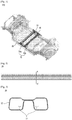
- a protecting device of a battery for an electrical automobile including a frame positioned in a lower portion of the electrical automobile 100, and one or more protecting bars positioned inside the frame 10, in which a vertical cross-section of the protecting bars 20 has a shape that includes at least two closed spaces 21a, 21b, and brims 22a, 22b that form the closed spaces 21a, 21b, the at least two closed spaces 21a, 21b are separated apart from each other, and the brims 22a, 22b are connected to each other.
- the vertical cross-section is preferably in such a shape that the brims 22a, 22b are connected at a location where one side of each of the closed spaces 21a, 21b faces each other.
- the one or more protecting bars 20 preferably have a predetermined bend radius.
- the one or more protecting bars 20 preferably have an upwardly-bent bend radius.
- the one or more protecting bars 20 preferably have a bend radius in a range of 3000 mm and 7000 mm.
- the one or more protecting bars 20 are two protecting bars 20a, 20b, and the two protecting bars 20a, 20b preferably have different bend radii from each other.
- an impact absorbing member 40 is positioned between the one or more protecting bars 20 and the frame 10.
- the one or more protecting bars 20 are preferably positioned in an upper portion of a battery mounted to the electrical automobile 100.
- a material of the one or more protecting bars 10 preferably is a martensitic steel having a strength in a range of 900 Mpa and 1700 Mpa.
- the impact energy received from outside is transmitted to the impact absorbing member and protecting bars of unique shapes disposed and installed in a lower portion of the electrical automobile and absorbed therein such that breakages of the battery are prevented effectively.
- the present disclosure does not need complicated assembly process and thus has simpler installation process than related protecting devices, and is more economical because constituent elements are mass producible.
- the protecting bars can be easily changed in shape according to need of a manufacturer, and are economical and convenient to manufacture.
- the constituent elements of a protecting device of a battery for an electrical automobile may be used as an integrated form or separated and used respectively. Further, depending on a form of use, some of the constituent elements may be omitted.
- a protecting device of a battery for an electrical automobile will be described with reference to Figs. 1 to 5 .
- the thicknesses of the lines illustrated in the drawings, sizes of the constituent elements, or the like may be exaggerated for the purpose of clarity and convenience.
- the terms described below are those that are defined in consideration of the function of the present disclosure, and may be varied according to the intent or the practice of the user or the operator. Accordingly, the definitions of these terms should be described based on the content throughout the disclosure.
- the protecting device includes a frame 10 that forms a body of a bottom 30 positioned in a lower portion of an electrical automobile 100, a protecting bar 20 positioned inside the frame 10, an impact absorbing member 40 that connects the protecting bar 20 to the frame 10, and a connector 50 that connects the protecting bar 20 to the bottom 30.
- the vertical cross-section of the protecting bar 20 is defined by a pair of closed spaces 21a, 21b, and brims 22a, 22b surrounding these, in which the brims 22a, 22b are characterized of being connected so as to separate the pair of closed spaces 21a, 21b by a predetermined distance (see Fig. 2 ).
- the lateral stiffness of the protecting bar 20 is increased.
- the protecting device does not require an increased amount of materials of the protecting device and still is resistant against the impact energy more effectively, and also is advantageous economically. It is to be understood that, in another embodiment, there may be two or more closed spaces 21 according to circumstances.
- the shape of the closed spaces 21a, 21b may be circular or bent, or may be modified into a variety of shapes such as a shape having a plurality of sides with rounded or pointed corners, and so on.
- the brims 22a, 22b that connect these closed spaces 21a, 21b are not limited to any specific shape or number with certain thickness, location of connection, or degree of separating the closed spaces 21a, 21b apart from each other, and so on.
- the brims 22a, 22b may be connected closer to a side opposite the side where the protecting bar 20 is connected to the bottom 30, and that the brims 22a, 22b may preferably be connected at a location where one side of each of the closed spaces 21a, 21b faces each other.
- the protecting bar 20 has a predetermined bend radius so as not to deliver the impact to the battery even when yielding to the impact energy (see Fig. 4 ).
- the bend radius may preferably be in a range of 3000 mm and 70000 mm such that when bent, the protecting bar 20 can be guided to be protruded in a direction opposite the place where the battery is positioned, by which the safety is added.
- the protecting bar 20 may additionally include the connector 50, which may act to restrict the protecting bar 20 to be connected to the bottom 30 more firmly, thus limiting a degree of bending when yielding to the impact energy.
- a plurality of same protecting bars 20 may be used for the protecting bar 20 that constitutes the protecting device 20, but the different forms may be used according to embodiments.
- the protecting bars 20a, 20b with different characteristics from each other may have different vertical cross-sectional shapes, or may have different bend radii from each other.
- the impact absorbing member 40 is positioned on both ends of each protecting bar, thus connecting the frame 10 with the protecting bar 20.
- the frame 10 is a constituent element that forms a body of the electrical automobile and also particularly determines the shape of the bottom 30.
- the frame 10 is configured with a material that has good durability and that is hardly deformable.
- the protecting bar 20 can be installed in a lower portion or an upper portion of the battery as mounted to the electrical automobile 100.
- a more effective arrangement may be provided by positioning the battery between the bottom 30 and the protecting bar 20, and installing the protecting bar 20 in an upwardly-bent form in the frame 10.
- the materials for the protecting bar 20, the frame 10 or the impact absorbing member 40 are not limited to any specific material.
- the protecting bar 20 may preferably be a martensitic steel having a strength in a range of 900 Mpa and 1700 Mpa.
Landscapes
- Engineering & Computer Science (AREA)
- Transportation (AREA)
- Mechanical Engineering (AREA)
- Chemical & Material Sciences (AREA)
- Combustion & Propulsion (AREA)
- Power Engineering (AREA)
- Sustainable Energy (AREA)
- Sustainable Development (AREA)
- Life Sciences & Earth Sciences (AREA)
- Architecture (AREA)
- Structural Engineering (AREA)
- Chemical Kinetics & Catalysis (AREA)
- Electrochemistry (AREA)
- General Chemical & Material Sciences (AREA)
- Battery Mounting, Suspending (AREA)
- Body Structure For Vehicles (AREA)
- Arrangement Or Mounting Of Propulsion Units For Vehicles (AREA)
Applications Claiming Priority (2)
| Application Number | Priority Date | Filing Date | Title |
|---|---|---|---|
| KR1020140045476A KR101506422B1 (ko) | 2014-04-16 | 2014-04-16 | 전기차량용 배터리의 보호장치 |
| PCT/KR2015/002989 WO2015160108A1 (fr) | 2014-04-16 | 2015-03-26 | Dispositif de protection de batterie pour automobile électrique |
Publications (2)
| Publication Number | Publication Date |
|---|---|
| EP3132957A1 true EP3132957A1 (fr) | 2017-02-22 |
| EP3132957A4 EP3132957A4 (fr) | 2018-01-03 |
Family
ID=53028710
Family Applications (1)
| Application Number | Title | Priority Date | Filing Date |
|---|---|---|---|
| EP15779841.4A Withdrawn EP3132957A4 (fr) | 2014-04-16 | 2015-03-26 | Dispositif de protection de batterie pour automobile électrique |
Country Status (5)
| Country | Link |
|---|---|
| US (1) | US10017036B2 (fr) |
| EP (1) | EP3132957A4 (fr) |
| KR (1) | KR101506422B1 (fr) |
| CN (1) | CN106414132B (fr) |
| WO (1) | WO2015160108A1 (fr) |
Families Citing this family (6)
| Publication number | Priority date | Publication date | Assignee | Title |
|---|---|---|---|---|
| CN105216601A (zh) * | 2015-10-28 | 2016-01-06 | 北京新能源汽车股份有限公司 | 用于车辆的电池吊挂保护系统及具有其的车辆 |
| DE102016110787A1 (de) * | 2016-06-13 | 2017-12-14 | Dr. Ing. H.C. F. Porsche Aktiengesellschaft | Batteriegehäuse einer Traktionsbatterie eines Kraftfahrzeugs |
| CN109808774B (zh) * | 2017-11-16 | 2021-05-18 | 上海汽车集团股份有限公司 | 电动汽车及其碰撞保护装置 |
| CN111183088B (zh) * | 2018-12-05 | 2021-01-12 | 翼科株式会社 | 电动汽车用的底盘及电动汽车 |
| KR102370338B1 (ko) | 2020-05-22 | 2022-03-04 | (주)아산 | 배터리 케이스용 보강재 및 그가 적용된 배터리 케이스 |
| JP7456302B2 (ja) | 2020-06-16 | 2024-03-27 | スズキ株式会社 | 車両のバッテリ保護構造 |
Family Cites Families (21)
| Publication number | Priority date | Publication date | Assignee | Title |
|---|---|---|---|---|
| US5501289A (en) * | 1993-01-22 | 1996-03-26 | Nissan Motor Co., Ltd. | Floor structure of electric vehicle |
| JP3345632B2 (ja) * | 1993-02-23 | 2002-11-18 | 国立環境研究所長 | 電気自動車用の車体 |
| JPH1142465A (ja) | 1997-07-25 | 1999-02-16 | Sintokogio Ltd | 洗浄方法およびその装置 |
| JP3817953B2 (ja) | 1999-02-22 | 2006-09-06 | マツダ株式会社 | 車両のバッテリ搭載構造 |
| JP4825583B2 (ja) | 2005-06-28 | 2011-11-30 | 本田技研工業株式会社 | 車体構造 |
| DE102006031452A1 (de) * | 2006-07-07 | 2008-01-17 | Dr.Ing.H.C. F. Porsche Ag | Querbrücke zur Versteifung des Tunnelbereiches einer Bodenstruktur eines Kraftfahrzeuges |
| JP4306783B2 (ja) * | 2007-12-14 | 2009-08-05 | 三菱自動車工業株式会社 | 電気自動車のバッテリユニット取付構造 |
| KR20120050234A (ko) | 2010-11-10 | 2012-05-18 | 현대자동차주식회사 | 고전압 배터리의 차량 설치구조 |
| BR112013011355A2 (pt) * | 2010-11-10 | 2016-08-09 | Honda Motor Co Ltd | estrutura de piso automotivo |
| KR101219399B1 (ko) * | 2010-11-24 | 2013-01-11 | 기아자동차주식회사 | 일체형 고전압 배터리 케이스 |
| US9022152B2 (en) * | 2010-12-24 | 2015-05-05 | Honda Motor Co., Ltd. | Automobile body structure |
| US8567856B2 (en) * | 2011-01-07 | 2013-10-29 | Tesla Motors, Inc. | Swept front torque box |
| US20120175177A1 (en) * | 2011-01-07 | 2012-07-12 | Ford Global Technologies Llc | Vehicle Battery Pack Frame |
| WO2012157857A2 (fr) * | 2011-05-19 | 2012-11-22 | 주식회사 엘지화학 | Bloc-batterie présentant une excellente fiabilité structurelle |
| DE102011102412B4 (de) * | 2011-05-25 | 2023-06-29 | Volkswagen Aktiengesellschaft | Anordnung einer Traktionsbatterie in einem Fahrzeug |
| DE102012000622A1 (de) | 2012-01-14 | 2013-07-18 | Volkswagen Aktiengesellschaft | Batterieanordnung für ein Fahrzeug mit Elektroantrieb |
| US8833839B2 (en) * | 2012-04-13 | 2014-09-16 | Toyota Motor Engineering & Manufacturing North America, Inc. | Impact protection structures for vehicles |
| KR101916466B1 (ko) | 2012-09-12 | 2018-11-07 | 현대자동차주식회사 | 완충구조를 갖는 자동차용 배터리 스택 |
| US9187136B1 (en) * | 2014-08-01 | 2015-11-17 | Honda Motor Co., Ltd. | Structural pan for automotive body/frame |
| US9487239B2 (en) * | 2014-10-10 | 2016-11-08 | Toyota Motor Engineering & Manufacturing North America, Inc. | Vehicle structures and methods of assembling the same |
| US9505442B2 (en) * | 2015-03-05 | 2016-11-29 | Ford Global Technologies, Llc | Energy absorbing rocker assembly |
-
2014
- 2014-04-16 KR KR1020140045476A patent/KR101506422B1/ko active IP Right Grant
-
2015
- 2015-03-26 US US15/293,714 patent/US10017036B2/en not_active Expired - Fee Related
- 2015-03-26 WO PCT/KR2015/002989 patent/WO2015160108A1/fr active Application Filing
- 2015-03-26 CN CN201580020141.2A patent/CN106414132B/zh not_active Expired - Fee Related
- 2015-03-26 EP EP15779841.4A patent/EP3132957A4/fr not_active Withdrawn
Also Published As
| Publication number | Publication date |
|---|---|
| EP3132957A4 (fr) | 2018-01-03 |
| WO2015160108A1 (fr) | 2015-10-22 |
| CN106414132B (zh) | 2019-05-31 |
| CN106414132A (zh) | 2017-02-15 |
| US20170043654A1 (en) | 2017-02-16 |
| US10017036B2 (en) | 2018-07-10 |
| KR101506422B1 (ko) | 2015-03-27 |
Similar Documents
| Publication | Publication Date | Title |
|---|---|---|
| EP3132957A1 (fr) | Dispositif de protection de batterie pour automobile électrique | |
| US10593915B2 (en) | Battery housing part for a traction battery of an electric or hybrid vehicle and battery housing | |
| EP2411246B1 (fr) | Structure pare-chocs | |
| CN106542002B (zh) | 一种车辆门槛加强件 | |
| US8770638B2 (en) | Bumper beam assembly for vehicle | |
| JP6688275B2 (ja) | 車両用電池パック保護構造およびそれを備えた車両 | |
| CN108091792B (zh) | 用于交通工具的蓄电池壳 | |
| RU2016120738A (ru) | Конструкция для защиты аккумулятора | |
| EP2853439B1 (fr) | Dispositif de amortissement de siège et siège de sécurité pour véhicule comportant celui-ci | |
| KR101402021B1 (ko) | 차량용 범퍼유닛 | |
| EP2703230A1 (fr) | Système d'assemblage de poutre de pare-chocs | |
| KR101916466B1 (ko) | 완충구조를 갖는 자동차용 배터리 스택 | |
| KR20140001385A (ko) | 자동차의 전방 차체 | |
| EP2949517A1 (fr) | Poutre arrière pour véhicule comportant une partie de renfort | |
| US9911952B2 (en) | Battery module for a motor vehicle | |
| EP3246965B1 (fr) | Ensemble d'éléments de batterie | |
| JP2014046765A (ja) | 車両の充電口構造 | |
| CN107492606B (zh) | 电池包箱体及具有其的车辆 | |
| KR100862476B1 (ko) | 자동차 도어의 임팩트 패드 | |
| CN203589625U (zh) | 一种汽车线束护线盒 | |
| KR101857263B1 (ko) | 조립식 보호 케이스 | |
| JP2015005384A (ja) | 電池パック | |
| KR102132307B1 (ko) | 전기자동차용 배터리 케이스의 보강유닛 | |
| JP2018106811A5 (fr) | ||
| KR20130114060A (ko) | 자동차용 범퍼 백빔 |
Legal Events
| Date | Code | Title | Description |
|---|---|---|---|
| PUAI | Public reference made under article 153(3) epc to a published international application that has entered the european phase |
Free format text: ORIGINAL CODE: 0009012 |
|
| 17P | Request for examination filed |
Effective date: 20161028 |
|
| AK | Designated contracting states |
Kind code of ref document: A1 Designated state(s): AL AT BE BG CH CY CZ DE DK EE ES FI FR GB GR HR HU IE IS IT LI LT LU LV MC MK MT NL NO PL PT RO RS SE SI SK SM TR |
|
| AX | Request for extension of the european patent |
Extension state: BA ME |
|
| DAV | Request for validation of the european patent (deleted) | ||
| DAX | Request for extension of the european patent (deleted) | ||
| A4 | Supplementary search report drawn up and despatched |
Effective date: 20171206 |
|
| RIC1 | Information provided on ipc code assigned before grant |
Ipc: B60R 16/04 20060101ALI20171130BHEP Ipc: B60K 1/04 20060101AFI20171130BHEP |
|
| GRAP | Despatch of communication of intention to grant a patent |
Free format text: ORIGINAL CODE: EPIDOSNIGR1 |
|
| STAA | Information on the status of an ep patent application or granted ep patent |
Free format text: STATUS: GRANT OF PATENT IS INTENDED |
|
| INTG | Intention to grant announced |
Effective date: 20200623 |
|
| STAA | Information on the status of an ep patent application or granted ep patent |
Free format text: STATUS: THE APPLICATION IS DEEMED TO BE WITHDRAWN |
|
| 18D | Application deemed to be withdrawn |
Effective date: 20201104 |