EP3132946B1 - Image board for rotary wheel and rotary wheel comprising same - Google Patents
Image board for rotary wheel and rotary wheel comprising same Download PDFInfo
- Publication number
- EP3132946B1 EP3132946B1 EP15780739.7A EP15780739A EP3132946B1 EP 3132946 B1 EP3132946 B1 EP 3132946B1 EP 15780739 A EP15780739 A EP 15780739A EP 3132946 B1 EP3132946 B1 EP 3132946B1
- Authority
- EP
- European Patent Office
- Prior art keywords
- base plate
- image
- image board
- weight
- rotary wheel
- Prior art date
- Legal status (The legal status is an assumption and is not a legal conclusion. Google has not performed a legal analysis and makes no representation as to the accuracy of the status listed.)
- Not-in-force
Links
- 239000012530 fluid Substances 0.000 claims description 13
- XLYOFNOQVPJJNP-UHFFFAOYSA-N water Substances O XLYOFNOQVPJJNP-UHFFFAOYSA-N 0.000 claims description 2
- 230000002528 anti-freeze Effects 0.000 claims 1
- 230000008878 coupling Effects 0.000 description 7
- 238000010168 coupling process Methods 0.000 description 7
- 238000005859 coupling reaction Methods 0.000 description 7
- 230000000694 effects Effects 0.000 description 5
- 239000007788 liquid Substances 0.000 description 3
- 239000000463 material Substances 0.000 description 3
- 230000003068 static effect Effects 0.000 description 3
- 230000008859 change Effects 0.000 description 2
- 230000009969 flowable effect Effects 0.000 description 2
- 230000008014 freezing Effects 0.000 description 2
- 238000007710 freezing Methods 0.000 description 2
- 230000004044 response Effects 0.000 description 2
- 230000002411 adverse Effects 0.000 description 1
- 230000007257 malfunction Effects 0.000 description 1
- QSHDDOUJBYECFT-UHFFFAOYSA-N mercury Chemical compound [Hg] QSHDDOUJBYECFT-UHFFFAOYSA-N 0.000 description 1
- 229910052753 mercury Inorganic materials 0.000 description 1
- 230000004048 modification Effects 0.000 description 1
- 238000012986 modification Methods 0.000 description 1
- 238000005096 rolling process Methods 0.000 description 1
- 230000001360 synchronised effect Effects 0.000 description 1
Images


Classifications
-
- B—PERFORMING OPERATIONS; TRANSPORTING
- B60—VEHICLES IN GENERAL
- B60B—VEHICLE WHEELS; CASTORS; AXLES FOR WHEELS OR CASTORS; INCREASING WHEEL ADHESION
- B60B7/00—Wheel cover discs, rings, or the like, for ornamenting, protecting, venting, or obscuring, wholly or in part, the wheel body, rim, hub, or tyre sidewall, e.g. wheel cover discs, wheel cover discs with cooling fins
- B60B7/0026—Wheel cover discs, rings, or the like, for ornamenting, protecting, venting, or obscuring, wholly or in part, the wheel body, rim, hub, or tyre sidewall, e.g. wheel cover discs, wheel cover discs with cooling fins characterised by the surface
- B60B7/0033—Wheel cover discs, rings, or the like, for ornamenting, protecting, venting, or obscuring, wholly or in part, the wheel body, rim, hub, or tyre sidewall, e.g. wheel cover discs, wheel cover discs with cooling fins characterised by the surface the dominant aspect being the surface appearance
- B60B7/0053—Wheel cover discs, rings, or the like, for ornamenting, protecting, venting, or obscuring, wholly or in part, the wheel body, rim, hub, or tyre sidewall, e.g. wheel cover discs, wheel cover discs with cooling fins characterised by the surface the dominant aspect being the surface appearance the surface being decorated
-
- B—PERFORMING OPERATIONS; TRANSPORTING
- B60—VEHICLES IN GENERAL
- B60B—VEHICLE WHEELS; CASTORS; AXLES FOR WHEELS OR CASTORS; INCREASING WHEEL ADHESION
- B60B7/00—Wheel cover discs, rings, or the like, for ornamenting, protecting, venting, or obscuring, wholly or in part, the wheel body, rim, hub, or tyre sidewall, e.g. wheel cover discs, wheel cover discs with cooling fins
- B60B7/20—Wheel cover discs, rings, or the like, for ornamenting, protecting, venting, or obscuring, wholly or in part, the wheel body, rim, hub, or tyre sidewall, e.g. wheel cover discs, wheel cover discs with cooling fins having an element mounted for rotation independently of wheel rotation
-
- B—PERFORMING OPERATIONS; TRANSPORTING
- B60—VEHICLES IN GENERAL
- B60B—VEHICLE WHEELS; CASTORS; AXLES FOR WHEELS OR CASTORS; INCREASING WHEEL ADHESION
- B60B7/00—Wheel cover discs, rings, or the like, for ornamenting, protecting, venting, or obscuring, wholly or in part, the wheel body, rim, hub, or tyre sidewall, e.g. wheel cover discs, wheel cover discs with cooling fins
- B60B7/01—Rings specially adapted for covering only the wheel rim or the tyre sidewall, e.g. removable tyre sidewall trim rings
-
- B—PERFORMING OPERATIONS; TRANSPORTING
- B60—VEHICLES IN GENERAL
- B60B—VEHICLE WHEELS; CASTORS; AXLES FOR WHEELS OR CASTORS; INCREASING WHEEL ADHESION
- B60B7/00—Wheel cover discs, rings, or the like, for ornamenting, protecting, venting, or obscuring, wholly or in part, the wheel body, rim, hub, or tyre sidewall, e.g. wheel cover discs, wheel cover discs with cooling fins
- B60B7/0026—Wheel cover discs, rings, or the like, for ornamenting, protecting, venting, or obscuring, wholly or in part, the wheel body, rim, hub, or tyre sidewall, e.g. wheel cover discs, wheel cover discs with cooling fins characterised by the surface
- B60B7/0033—Wheel cover discs, rings, or the like, for ornamenting, protecting, venting, or obscuring, wholly or in part, the wheel body, rim, hub, or tyre sidewall, e.g. wheel cover discs, wheel cover discs with cooling fins characterised by the surface the dominant aspect being the surface appearance
- B60B7/004—Wheel cover discs, rings, or the like, for ornamenting, protecting, venting, or obscuring, wholly or in part, the wheel body, rim, hub, or tyre sidewall, e.g. wheel cover discs, wheel cover discs with cooling fins characterised by the surface the dominant aspect being the surface appearance the surface being painted
-
- B—PERFORMING OPERATIONS; TRANSPORTING
- B60—VEHICLES IN GENERAL
- B60B—VEHICLE WHEELS; CASTORS; AXLES FOR WHEELS OR CASTORS; INCREASING WHEEL ADHESION
- B60B7/00—Wheel cover discs, rings, or the like, for ornamenting, protecting, venting, or obscuring, wholly or in part, the wheel body, rim, hub, or tyre sidewall, e.g. wheel cover discs, wheel cover discs with cooling fins
- B60B7/06—Fastening arrangements therefor
- B60B7/061—Fastening arrangements therefor characterised by the part of the wheels to which the discs, rings or the like are mounted
- B60B7/066—Fastening arrangements therefor characterised by the part of the wheels to which the discs, rings or the like are mounted to the hub
Definitions
- the present invention relates to an image board for a rotary wheel and a rotary wheel including the same, and more particularly, to an image board for a rotary wheel that is mounted on a rotary wheel of a vehicle such as a car or a bicycle and displays an image at a fixed position regardless of rotation of the rotary wheel, and a rotary wheel including the image board.
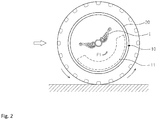
- FIGS. 1 to 2 illustrate the configuration of an image board 10 for a rotary wheel in the related art.
- the image board 10 of the related art is vertically mounted on a wheel frame 20 of a vehicle 1 to be rotatable through a bearing (not shown). Further, the image board 10 has a weight 11 for predetermined load at a lower portion and various images I such as a logo, an emblem, or and advertising image on the outer side.
- the weight 11 keeps the position without rotating by the load of the weight 11 and the image I is displayed at a fixed position, so the image board 10 can provide an advertising effect and a decorative effect as an accessory.
- the weight 11 is eccentrically disposed at the lower portion of the image board 10, when the weight 11 is rotated with the image board 10 due to malfunction of the bearing, vibration is generated by an eccentric weight change of the weight 11, in which the heavier the weight 11, the more the vibration increases, and it adversely influences the steering function of the vehicle 1.
- US 4 280 293 discloses a stationary display member which is mounted on the rotating hub cap of a wheel of a vehicle, or other rotating member which comprises a disc-like member coaxially mounted on the hub cap to be freely rotatable about the axis of rotation of the hub cap.
- the disc-like member has an internal chamber which is partially filled with a flowable material, such as mercury. The flowable material collects at the bottom of the chamber, and it forms an off-set weight which prevents the disc-like member from turning as the hub cap turns about is axis of rotation.
- EP 1 106 389 discloses a static plate device mounted on a rotating body so as to maintain a static state without becoming synchronized with a rotation of the rotating body.
- the static plate appears to remain stationary even as the rotating body rotates.
- KR 2013 0047922 discloses a wheel cover for a vehicle provided to regularly maintain a fixed state with a simple operation structure regardless of the rotation of a wheel.
- the wheel cover comprises a cover plate and a weight. which maintains the cover plates in a fixed position regardless of the rotation of the wheel and comprises a housing and a fluid filling.
- the housing comprises a circular chamber inside, and the fluid filling is partially filled inside the chamber.
- JP 2001 354001 discloses a basic disk having a first eccentric weight rotatably fitted to a center small shaft n a casing having a transparent lid mounted on the wheel.
- An indicator body support panel having a second eccentric weight is rotatably provided on the basic disk.
- the present invention has been made in an effort to solve the problems and an object of the present invention is to provide an image board for a rotary wheel that can always display a still image by applying load to return a main weight disposed at a lower portion of a base plate to the original position using a compensating weight even if the main weight is rotated with the base plate that is rotated by friction on bearing balls, driving wind, and inertia force, and a rotary wheel including the image board.
- an image board for a rotary wheel which can be mounted on a rotary wheel of a vehicle and displays an image at a fixed position regardless of rotation of the rotary wheel, includes: a base plate that can be vertically disposed on the outer side of or inside a wheel frame of the rotary wheel to be rotatable independently from the wheel frame, has a predetermined image on one or both sides, and has a chamber having a space circumferentially extending around a rotational axis; a main weight that is fixed at a lower potion of the base plate and applies load to the lower portion of the base plate; and a compensating weight that is disposed in the space and applies load to return the main weight to an original position by moving in the space when the main weight rotates in a predetermined direction.
- the main weight is an impeller that is rotated in the opposite direction to the wheel frame by driving wind that comes when the vehicle runs.
- the compensating weight may be fluid that is injected in the space by a predetermined amount and applies load to the base plate by moving to be leveled by its weight when the main weight rotates.
- the image board may further include an expansion plate that is vertically disposed, is larger in diameter than the base plate, is mounted on a side or around the edge of the base plate, and has a predetermined image on one or both sides.
- a rotary wheel that can be mounted at a lower portion of a vehicle, and can move the vehicle by rotating, and displays an image at a fixed position, includes: a wheel frame that is fitted in a tire and rotated by power; and an image board that includes a base plate that is vertically disposed on the outer side of or inside the wheel frame of the rotary wheel to be rotatable independently from the wheel frame, has a predetermined image on one or both sides, and has a chamber having a space circumferentially extending around a rotational axis, a main weight that is fixed at a lower potion of the base plate and applies load to the lower portion of the base plate, and a compensating weight that is disposed in the space and applies load to return the main weight to an original position by moving in the space when the main weight rotates in a predetermined direction.
- the main weight is an impeller that is rotated in the opposite direction to the wheel frame by driving wind that comes when the vehicle runs.
- the compensating weight in the chamber of the base plate applies load to return the main weight to the original position by moving in the space of the chamber, so it is possible to display an image at a fixed position.
- the weight when fluid injected in the space by a predetermined amount is used as the compensating weight, the weight can apply load by instantaneously moving to be leveled in the space when the main weight is rotated, so it is possible to maximize the response speed for applying load to return the main weight to the original position.
- the expansion plate having a predetermined image on the outer side is vertically disposed on a side or around the edge of the base plate, it is possible to make the base plate thin and it is also possible to largely increase the area where an image can be disposed in accordance with the diameter of the wheel frame.
- the expansion plate can be separated from the base plate, a user can freely change the image. Furthermore, when the base plate is vertically disposed inside the wheel frame, it is possible to fit the expansion plate inside the spokes of the wheel frame through the slit formed at a predetermined position on the expansion plate, so convenience for the user is improved and the expansion plate can be easily replaced.
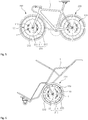
- a rotary wheel 200 which is a rotary wheel mounted at a lower portion of a vehicle 1 such as a car or a bicycle and displaying an image I at a fixed position while moving the vehicle (1) by rotating, includes a wheel frame 210 and an image board 100.
- the vehicle 1 can be moved by the rotary wheel 200 and the rotary wheel 200 is a moving device having the wheel frame 210 on which the image board 100 can be mounted.
- the vehicle 1 includes all of not only a car, bicycle, and a cart, but also other vehicles equipped with the rotary wheel 200 having the wheel frame 210 such as a motor cycle, a golf cart, a wheelchair, and a baby walker.
- the wheel frame 210 which is a wheel member to be fitted in a tire 212 and rotated by power, is mounted with the image board 100 that can independently rotate, may be formed in an integrated type such as the wheel frames for cars, depending on the type of the vehicle 1, and may be fitted on a driving shaft to be rotatable.
- the wheel frame 210 similar to those of a bicycle, may include a rim 214 that is fitted in a tire 212, a rotary shaft 211 that is disposed at the center of the rim 214 and rotated by torque from a chain or an engine, and a plurality of spokes 215 that connects the rotary shaft 211 and the rim 214 to each other to support load.
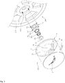
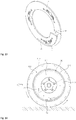
- the image board 100 a part independently rotatably mounted on the wheel frame 210 and displaying an image I at a fixed position regardless of rotation of the wheel frame 210, as illustrated in FIGS. 3 to 9 , includes a base plate 110, a main weight 120, and a compensating weight 130.
- the base plate 110 which is a disc-shaped member forming the body of the image board 100, is vertically disposed on the outer side of or inside the wheel frame 210 of the rotary wheel 200 to be rotatable independently from the wheel frame 210.
- the base plate 110 has a predetermined image I on a side or both sides and has a chamber 112 providing a space 111 circumferentially extending around a rotational axis L.
- the base plate 110 may be coupled to a bearing 150 and vertically disposed on the outer side of or inside the wheel frame 210 such that it can rotate independently from the wheel frame 210 through the bearing 150.
- the image I which includes various design images such as a logo, an emblem, or an advertising image, may be intactly printed on the base plate 110 as it is, a sheet printed with the image I may be attached to the base plate 110, a specific image plate printed with the image I may be mounted on the base plate 110, or a symbol having a specific shape may be mounted on the base plate 110.
- the image I when the image I is not exposed (illustrated) on the inner side connected to the driving shaft like the wheel frame 210 of a car, but is exposed to the outside on the outer side, it is disposed on the outer side of the base plate 110. Further, when the image I is exposed to the outside on both sides through the spoke 215 like the wheel frame 210 of a bicycle, it is preferable to dispose the image on both sides of the base plate 110, thereby increasing the effect of exposing the image.
- the chamber 112 which provides a space and a passage for moving the compensating weight 130, has a ring-shaped space 111 that is disposed at a side or at the center of the base plate 110 and rotated about the rotational axis L of the base plate 110.
- the disc-shaped base plate 110 is exemplified in the drawings, the present invention is not limited thereto and the entire shape is not limited, including an ellipse, a triangle, a rectangle, and a polygon etc. However, it is preferable that the chamber 112 has an entirely circular shape such as an O-shape or a C-shape.
- the image board 100 is rotatably mounted on the outer side of the wheel frame 210, and to this end, a coupling plate 140, a bearing 150, and a fixing shaft 160 are further included.
- the coupling plate 140 which is a plate vertically coupled to a side of the wheel frame 210 to support the image board 100 so that the image board 100 is rotatably mounted on the wheel frame 210, is formed in a plate shape and has a plurality of fastening holes 141 around it for inserting screws 217 protruding from the wheel frame 210 and a fastening hole 142 at the center for coupling the bearing 150.
- the bearing 150 which is coupled to the center of the coupling plate 140 to physically isolate the image board 100 from rotation of the wheel frame 210, is fixed to the center of the coupling plate 140 around the outer side and is fitted on the fixing shaft 160.
- the bearing 150 is composed of a plurality of individual bearings 151 and 152 having different inner diameters and sequentially fitted in larger ones, so torque F1 (see FIG. 11 ) that rotates the image board 100 can be reduced by friction and inertia force generated by rotation of the individual bearings 151 and 152.
- the fixing shaft 160 which is fitted in the center of the bearing 150 between the bearing 150 and the base plate 110 and is rotatably coupled to the coupling plate 140 through the bearing 150, as illustrated in FIG. 3 , has a first end fitted in the bearing 150 and a second end coupled to the center of the base plate 110.
- fastening holes 161 for thread-fastening are formed at the second end of the fixing shaft 160, so, as illustrated in FIG. 4 , the fixing shaft 160 can be firmly fastened inside the base plate 110 by screws 162 that are tightened in fastening holes 113 formed through the base plate 110 at positions corresponding to the fastening holes 161.
- the image board 100 may be mounted on the outer side of the wheel frame 210, but, as illustrated in FIGS. 8 and 9 , the image board 100 may be rotatably mounted inside the wheel frame 210.
- the bearing 150 is fitted on a rotary shaft 211 of the wheel frame 210 and the bearing 150 is fitted in the center of the base plate 110, whereby the image board 100 can be vertically mounted on the outer side of the wheel frame 210 to be independently rotatable.
- a specific coupling plate may be provided to more strongly fit the bearing 150 on the rotary shaft 211 or more strongly fit the bearing 150 in the base plate 110.
- the base plate 110 may be vertically disposed inside the wheel frame 210, whereby the image board 100 can be protected from the outside by the spoke 215 without protruding to the outside and the external appearance can be improved.
- the bearing 150 may be laterally fitted on the horizontal rotary shaft 211 of the wheel frame 210 by the hole therein and the base plate 110 may be fitted on the bearing 150 and vertically disposed inside the wheel frame 210 such that it can be rotated independently from the wheel frame 210 by the bearing 150.
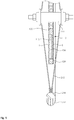
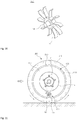
- the main weight 120 which is a part applying load to the lower portion of the base plate 110 so that the image I on the image board 100 can be displayed always at a fixed position even though the wheel frame 210 is rotated, as illustrated in FIGS. 3 and 4 , is fixed at an eccentric lower portion on the base plate 110 with the image I vertically disposed to be displayed to the outside and applies load to the lower portion of the base plate 110.
- main weight 120 is exemplified as a smooth curved bar in the drawings, is not limited thereto and its shape is not limited as long as it can minimize friction with external air while applying load to the lower portion of the base plate 110 such as a disc or a sphere.
- the main weight 120 is an impeller 120 that is rotated in the opposite direction to the wheel frame 210 by driving wind that comes when the vehicle 1 runs.
- the impeller 120 generates torque F2 (see FIG. 11 ) in the opposite direction to offset the torque F1 generated by rotation of the wheel frame 210 to display the image I always at a fixed position on the base plate 110 even though the wheel frame 210 is rotated at a high speed.
- an end of a rotary shaft 121 of the impeller 120 is fixed to the lower portion of the base plate 110 and a plurality of blades 122 that is curved or inclined to be rotated in the opposite direction to the wheel frame 210 by the driving wind from the front is arranged around the rotary shaft 121. Accordingly, as the blades 122 are rotated about the rotary shaft 121 by driving wind, the torque F2 is generated.
- the impeller 120 that is rotated in the opposite direction to the wheel frame 210 by driving wind that comes when the vehicle 1 runs is mounted at the lower portion of the base plate 110, the torque F1 generated by the wheel frame 210 rotating when the vehicle 1 runs is offset by inertial force F2 generated by rotation of the impeller 120 and friction force F2 on the blades 122, whereby it is possible to display the image I at a fixed position regardless of the rotation of the wheel frame 210.
- the inertia force F2 generated in the opposite direction to the rotational direction of the wheel frame 210 when the blades 122 are rotated is caused by a gyro phenomenon.
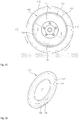
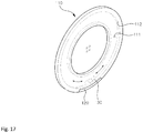
- the image board may further include an expansion plate 113 that is relatively larger in diameter than the base plate 110, is vertically disposed on a side or around the edge of the base plate 110, and has a predetermined image I on one or both sides.
- the expansion plate 113 is a large-diameter disc covering a side of the base plate 110 and, may be fastened to the base plate 110 at the center of the inner side and may have the image I on the outer side.
- the expansion plate 113 may be formed in a ring shape to be fitted around the base plate 110 and may have an image I, which relates to or is independent from the image on the base plate 110, on the outer side.
- a step 116 for supporting a side around the inner edge of the expansion plate 113 is formed around the edge of the base plate 110 and the expansion plate 113 is thread-fastened firmly to the base plate 110 with the side around the inner edge supported on the step 116 and the other side around the inner edge pressed by a fastening ring.
- the main weight 120 applying load to the lower portion may be mounted at an eccentric lower portion of the expansion plate 113. Accordingly, the main weight 120 is further spaced from the rotational axis L as compared with the main weight disposed at a lower portion of the chamber 112, the torque F2 generated in the base plate 110 is increased.
- the expansion plate 113 is formed in a ring shape and fitted around the base plate, as illustrated in FIG. 13 , it is preferable that the expansion plate 113 is made of a flexible material and has a slit 115 formed in the width direction at a predetermined position so that it can be fitted inside the spokes 215 through the slit 115 to be detachably coupled to the base plate 110.
- the compensating weight 130 is disposed in the space 111 and, applies load to return the main weight 120 to the original position by moving in the space 111 when the main weight 120 is rotated in any directions together with the base plate 110.
- the compensating weight 130 may be fluid 130 that is injected in the space 111 by a predetermined amount to apply load to the base plate 110 so that the main weight 120 can return to the original position, by moving to be leveled by its load when the main weight 120 is rotated.
- antifreezing liquid having a low freezing temperature relative to common liquid such as water makes it possible to normally operate the image board 100 without the fluid 130 freezing in a coldest season such as winter or in an intensively cold area such as Russia.
- the liquid instantaneously moves to be leveled in the space 111 when the main weight 120 rotates, so it is possible to maximize the response speed for applying load to return the main weight 120 to the original position.
- the compensating weight 130 may be a disc or a sphere to apply load to a wheel cover 140 so that the main weight 120 returns to the original position, by rolling on the inner side of the space 111 to move down in the space 111 when the main weight 120 rotates.
Landscapes
- Engineering & Computer Science (AREA)
- Mechanical Engineering (AREA)
- Fittings On The Vehicle Exterior For Carrying Loads, And Devices For Holding Or Mounting Articles (AREA)
- Motorcycle And Bicycle Frame (AREA)
- Toys (AREA)
Applications Claiming Priority (3)
| Application Number | Priority Date | Filing Date | Title |
|---|---|---|---|
| KR20140044227 | 2014-04-14 | ||
| KR1020150035796A KR101768044B1 (ko) | 2014-04-14 | 2015-03-16 | 회전바퀴용 이미지보드 및 이를 포함하는 회전바퀴 |
| PCT/KR2015/003094 WO2015160111A1 (ko) | 2014-04-14 | 2015-03-30 | 회전바퀴용 이미지보드 및 이를 포함하는 회전바퀴 |
Publications (3)
| Publication Number | Publication Date |
|---|---|
| EP3132946A1 EP3132946A1 (en) | 2017-02-22 |
| EP3132946A4 EP3132946A4 (en) | 2017-12-20 |
| EP3132946B1 true EP3132946B1 (en) | 2019-01-30 |
Family
ID=54426953
Family Applications (1)
| Application Number | Title | Priority Date | Filing Date |
|---|---|---|---|
| EP15780739.7A Not-in-force EP3132946B1 (en) | 2014-04-14 | 2015-03-30 | Image board for rotary wheel and rotary wheel comprising same |
Country Status (6)
| Country | Link |
|---|---|
| US (1) | US10046596B2 (enExample) |
| EP (1) | EP3132946B1 (enExample) |
| JP (1) | JP6484701B2 (enExample) |
| KR (1) | KR101768044B1 (enExample) |
| CN (1) | CN106660389B (enExample) |
| ES (1) | ES2722426T3 (enExample) |
Families Citing this family (3)
| Publication number | Priority date | Publication date | Assignee | Title |
|---|---|---|---|---|
| JP7138882B2 (ja) | 2018-03-14 | 2022-09-20 | 株式会社サンケミカル | スポークホイールの加飾装置 |
| DE102019202507B4 (de) * | 2019-02-25 | 2021-02-18 | Volkswagen Aktiengesellschaft | Drehbares Zierelement |
| CN115503390B (zh) * | 2022-08-24 | 2025-08-29 | 北京汽车股份有限公司 | 一种轮毂车标定向装置及汽车 |
Family Cites Families (17)
| Publication number | Priority date | Publication date | Assignee | Title |
|---|---|---|---|---|
| JPS5639683Y2 (enExample) * | 1978-06-27 | 1981-09-16 | ||
| US4280293A (en) * | 1979-12-26 | 1981-07-28 | Kovalenko Eugene N | Stationary display member for a rotating hub cap |
| JP3126124B1 (ja) * | 1999-12-03 | 2001-01-22 | 株式会社シンセイ | 静止板装置および静止板付き回転体装置 |
| US20020125761A1 (en) * | 1999-12-03 | 2002-09-12 | Kabushiki Kaisha Shinsei | Static plate device and static plate-equipped rotary body |
| JP2001354001A (ja) * | 2000-06-12 | 2001-12-25 | Shoei Shoji Kk | 自動車ホイ−ル取り付用表示装置 |
| KR20020047469A (ko) | 2000-12-13 | 2002-06-22 | 류정열 | 자동차의 휠 내부구조 |
| JP2002370501A (ja) * | 2001-04-11 | 2002-12-24 | Mitsumi Electric Co Ltd | ホイールキャップ |
| KR200252849Y1 (ko) * | 2001-07-24 | 2001-11-23 | 류충섭 | 자동차용 휠커버 |
| KR20040107907A (ko) | 2003-06-14 | 2004-12-23 | 배운호 | 정지된 광고판을 갖는 타이어휠 |
| JP2005178493A (ja) * | 2003-12-18 | 2005-07-07 | Ntn Corp | ホイールキャップ |
| KR100767600B1 (ko) | 2007-03-29 | 2007-10-17 | 이일섭 | 차량의 바퀴에 부착되는 무회전 광고장치 |
| KR101167826B1 (ko) * | 2009-07-08 | 2012-07-26 | 류충섭 | 차량용 휠 커버 구조물 |
| KR101147057B1 (ko) * | 2010-12-23 | 2012-05-17 | 김상국 | 차량의 휠캡용 광고장치 |
| US8517474B2 (en) * | 2011-06-20 | 2013-08-27 | Mazen Yousef Falah Salah | Non-rotating wheel cap |
| KR101380303B1 (ko) * | 2011-11-01 | 2014-04-01 | 이주원 | 차량용 휠커버 |
| KR101540103B1 (ko) * | 2013-12-04 | 2015-07-30 | 유충섭 | 차량용 휠커버 장치 |
| US20150170558A1 (en) * | 2013-12-12 | 2015-06-18 | Mazen Yousef Falah Salah | Non-Rotating Wheel Cap |
-
2015
- 2015-03-16 KR KR1020150035796A patent/KR101768044B1/ko active Active
- 2015-03-30 JP JP2017506236A patent/JP6484701B2/ja not_active Expired - Fee Related
- 2015-03-30 CN CN201580020018.0A patent/CN106660389B/zh not_active Expired - Fee Related
- 2015-03-30 US US15/304,405 patent/US10046596B2/en active Active
- 2015-03-30 ES ES15780739T patent/ES2722426T3/es active Active
- 2015-03-30 EP EP15780739.7A patent/EP3132946B1/en not_active Not-in-force
Non-Patent Citations (1)
| Title |
|---|
| None * |
Also Published As
| Publication number | Publication date |
|---|---|
| KR101768044B1 (ko) | 2017-08-30 |
| JP2017514753A (ja) | 2017-06-08 |
| EP3132946A1 (en) | 2017-02-22 |
| CN106660389A (zh) | 2017-05-10 |
| US20170043615A1 (en) | 2017-02-16 |
| US10046596B2 (en) | 2018-08-14 |
| CN106660389B (zh) | 2019-01-11 |
| KR20150118529A (ko) | 2015-10-22 |
| ES2722426T3 (es) | 2019-08-12 |
| EP3132946A4 (en) | 2017-12-20 |
| JP6484701B2 (ja) | 2019-03-13 |
Similar Documents
| Publication | Publication Date | Title |
|---|---|---|
| EP2537683B1 (en) | Non-rotating wheel cap | |
| US5490342A (en) | Non-rotating wheel cover | |
| US20150170558A1 (en) | Non-Rotating Wheel Cap | |
| JP3737971B2 (ja) | 回転体に取り付ける非回転表示器 | |
| EP3132946B1 (en) | Image board for rotary wheel and rotary wheel comprising same | |
| JP2012055860A (ja) | 三次元ボールミル | |
| KR20130047922A (ko) | 차량용 휠커버 | |
| JP2017514753A5 (enExample) | ||
| US20130276571A1 (en) | Advanced Steering Wheel | |
| PT80767B (en) | A hub cap for a motor vehicle wheel | |
| US20120286560A1 (en) | Wheel cover for a vehicle | |
| US20070164600A1 (en) | Wheel rim structure | |
| KR100989188B1 (ko) | 밸런싱 기능을 가진 차량용 휠 캡 | |
| KR101540103B1 (ko) | 차량용 휠커버 장치 | |
| WO2012078344A2 (en) | Advanced steering wheel | |
| JP2001354001A (ja) | 自動車ホイ−ル取り付用表示装置 | |
| KR20090004092U (ko) | 차량의 바퀴에 부착되는 무회전 광고장치 | |
| KR200307559Y1 (ko) | 회전체에 고정되는 비회전 표시기 | |
| KR101276411B1 (ko) | 차량의 광고용 휠캡 어셈블리 | |
| JP2005178493A (ja) | ホイールキャップ | |
| JP2017502878A5 (enExample) | ||
| KR100594631B1 (ko) | 차량용 휠캡에 부착되는 비회전 엠블렘 표시기 | |
| JP2005001617A (ja) | 車輪用表示器 | |
| KR200311926Y1 (ko) | 회전되지 않는 광고판을 갖는 타이어휠 | |
| JP2001063302A (ja) | タイヤホイールのマーク非回転表示装置 |
Legal Events
| Date | Code | Title | Description |
|---|---|---|---|
| STAA | Information on the status of an ep patent application or granted ep patent |
Free format text: STATUS: THE INTERNATIONAL PUBLICATION HAS BEEN MADE |
|
| PUAI | Public reference made under article 153(3) epc to a published international application that has entered the european phase |
Free format text: ORIGINAL CODE: 0009012 |
|
| STAA | Information on the status of an ep patent application or granted ep patent |
Free format text: STATUS: REQUEST FOR EXAMINATION WAS MADE |
|
| 17P | Request for examination filed |
Effective date: 20161114 |
|
| AK | Designated contracting states |
Kind code of ref document: A1 Designated state(s): AL AT BE BG CH CY CZ DE DK EE ES FI FR GB GR HR HU IE IS IT LI LT LU LV MC MK MT NL NO PL PT RO RS SE SI SK SM TR |
|
| AX | Request for extension of the european patent |
Extension state: BA ME |
|
| DAV | Request for validation of the european patent (deleted) | ||
| DAX | Request for extension of the european patent (deleted) | ||
| A4 | Supplementary search report drawn up and despatched |
Effective date: 20171122 |
|
| RIC1 | Information provided on ipc code assigned before grant |
Ipc: B60B 7/01 20060101ALI20171116BHEP Ipc: B60B 7/00 20060101AFI20171116BHEP |
|
| RAP1 | Party data changed (applicant data changed or rights of an application transferred) |
Owner name: MIRYOON W&T CORPORATION |
|
| RIN1 | Information on inventor provided before grant (corrected) |
Inventor name: RYU, SUNG SUG Inventor name: OH, IN SUNG Inventor name: KIM, YOON HWA Inventor name: KIM, SUNG HUM Inventor name: YOO, CHUNG SUP |
|
| STAA | Information on the status of an ep patent application or granted ep patent |
Free format text: STATUS: EXAMINATION IS IN PROGRESS |
|
| 17Q | First examination report despatched |
Effective date: 20180829 |
|
| GRAP | Despatch of communication of intention to grant a patent |
Free format text: ORIGINAL CODE: EPIDOSNIGR1 |
|
| STAA | Information on the status of an ep patent application or granted ep patent |
Free format text: STATUS: GRANT OF PATENT IS INTENDED |
|
| INTG | Intention to grant announced |
Effective date: 20181015 |
|
| GRAS | Grant fee paid |
Free format text: ORIGINAL CODE: EPIDOSNIGR3 |
|
| GRAA | (expected) grant |
Free format text: ORIGINAL CODE: 0009210 |
|
| STAA | Information on the status of an ep patent application or granted ep patent |
Free format text: STATUS: THE PATENT HAS BEEN GRANTED |
|
| AK | Designated contracting states |
Kind code of ref document: B1 Designated state(s): AL AT BE BG CH CY CZ DE DK EE ES FI FR GB GR HR HU IE IS IT LI LT LU LV MC MK MT NL NO PL PT RO RS SE SI SK SM TR |
|
| REG | Reference to a national code |
Ref country code: GB Ref legal event code: FG4D |
|
| REG | Reference to a national code |
Ref country code: CH Ref legal event code: EP |
|
| REG | Reference to a national code |
Ref country code: AT Ref legal event code: REF Ref document number: 1092938 Country of ref document: AT Kind code of ref document: T Effective date: 20190215 |
|
| REG | Reference to a national code |
Ref country code: IE Ref legal event code: FG4D |
|
| REG | Reference to a national code |
Ref country code: DE Ref legal event code: R096 Ref document number: 602015024094 Country of ref document: DE |
|
| REG | Reference to a national code |
Ref country code: LT Ref legal event code: MG4D |
|
| REG | Reference to a national code |
Ref country code: NL Ref legal event code: MP Effective date: 20190130 |
|
| PG25 | Lapsed in a contracting state [announced via postgrant information from national office to epo] |
Ref country code: SE Free format text: LAPSE BECAUSE OF FAILURE TO SUBMIT A TRANSLATION OF THE DESCRIPTION OR TO PAY THE FEE WITHIN THE PRESCRIBED TIME-LIMIT Effective date: 20190130 Ref country code: NL Free format text: LAPSE BECAUSE OF FAILURE TO SUBMIT A TRANSLATION OF THE DESCRIPTION OR TO PAY THE FEE WITHIN THE PRESCRIBED TIME-LIMIT Effective date: 20190130 Ref country code: LT Free format text: LAPSE BECAUSE OF FAILURE TO SUBMIT A TRANSLATION OF THE DESCRIPTION OR TO PAY THE FEE WITHIN THE PRESCRIBED TIME-LIMIT Effective date: 20190130 Ref country code: PL Free format text: LAPSE BECAUSE OF FAILURE TO SUBMIT A TRANSLATION OF THE DESCRIPTION OR TO PAY THE FEE WITHIN THE PRESCRIBED TIME-LIMIT Effective date: 20190130 Ref country code: PT Free format text: LAPSE BECAUSE OF FAILURE TO SUBMIT A TRANSLATION OF THE DESCRIPTION OR TO PAY THE FEE WITHIN THE PRESCRIBED TIME-LIMIT Effective date: 20190530 Ref country code: NO Free format text: LAPSE BECAUSE OF FAILURE TO SUBMIT A TRANSLATION OF THE DESCRIPTION OR TO PAY THE FEE WITHIN THE PRESCRIBED TIME-LIMIT Effective date: 20190430 Ref country code: FI Free format text: LAPSE BECAUSE OF FAILURE TO SUBMIT A TRANSLATION OF THE DESCRIPTION OR TO PAY THE FEE WITHIN THE PRESCRIBED TIME-LIMIT Effective date: 20190130 |
|
| PGFP | Annual fee paid to national office [announced via postgrant information from national office to epo] |
Ref country code: ES Payment date: 20190531 Year of fee payment: 5 Ref country code: IT Payment date: 20190529 Year of fee payment: 5 Ref country code: DE Payment date: 20190529 Year of fee payment: 5 |
|
| REG | Reference to a national code |
Ref country code: ES Ref legal event code: FG2A Ref document number: 2722426 Country of ref document: ES Kind code of ref document: T3 Effective date: 20190812 |
|
| REG | Reference to a national code |
Ref country code: AT Ref legal event code: MK05 Ref document number: 1092938 Country of ref document: AT Kind code of ref document: T Effective date: 20190130 |
|
| PG25 | Lapsed in a contracting state [announced via postgrant information from national office to epo] |
Ref country code: IS Free format text: LAPSE BECAUSE OF FAILURE TO SUBMIT A TRANSLATION OF THE DESCRIPTION OR TO PAY THE FEE WITHIN THE PRESCRIBED TIME-LIMIT Effective date: 20190530 Ref country code: BG Free format text: LAPSE BECAUSE OF FAILURE TO SUBMIT A TRANSLATION OF THE DESCRIPTION OR TO PAY THE FEE WITHIN THE PRESCRIBED TIME-LIMIT Effective date: 20190430 Ref country code: HR Free format text: LAPSE BECAUSE OF FAILURE TO SUBMIT A TRANSLATION OF THE DESCRIPTION OR TO PAY THE FEE WITHIN THE PRESCRIBED TIME-LIMIT Effective date: 20190130 Ref country code: GR Free format text: LAPSE BECAUSE OF FAILURE TO SUBMIT A TRANSLATION OF THE DESCRIPTION OR TO PAY THE FEE WITHIN THE PRESCRIBED TIME-LIMIT Effective date: 20190501 Ref country code: RS Free format text: LAPSE BECAUSE OF FAILURE TO SUBMIT A TRANSLATION OF THE DESCRIPTION OR TO PAY THE FEE WITHIN THE PRESCRIBED TIME-LIMIT Effective date: 20190130 Ref country code: LV Free format text: LAPSE BECAUSE OF FAILURE TO SUBMIT A TRANSLATION OF THE DESCRIPTION OR TO PAY THE FEE WITHIN THE PRESCRIBED TIME-LIMIT Effective date: 20190130 |
|
| PGFP | Annual fee paid to national office [announced via postgrant information from national office to epo] |
Ref country code: FR Payment date: 20190425 Year of fee payment: 5 |
|
| PG25 | Lapsed in a contracting state [announced via postgrant information from national office to epo] |
Ref country code: AL Free format text: LAPSE BECAUSE OF FAILURE TO SUBMIT A TRANSLATION OF THE DESCRIPTION OR TO PAY THE FEE WITHIN THE PRESCRIBED TIME-LIMIT Effective date: 20190130 Ref country code: MC Free format text: LAPSE BECAUSE OF FAILURE TO SUBMIT A TRANSLATION OF THE DESCRIPTION OR TO PAY THE FEE WITHIN THE PRESCRIBED TIME-LIMIT Effective date: 20190130 Ref country code: SK Free format text: LAPSE BECAUSE OF FAILURE TO SUBMIT A TRANSLATION OF THE DESCRIPTION OR TO PAY THE FEE WITHIN THE PRESCRIBED TIME-LIMIT Effective date: 20190130 Ref country code: DK Free format text: LAPSE BECAUSE OF FAILURE TO SUBMIT A TRANSLATION OF THE DESCRIPTION OR TO PAY THE FEE WITHIN THE PRESCRIBED TIME-LIMIT Effective date: 20190130 Ref country code: EE Free format text: LAPSE BECAUSE OF FAILURE TO SUBMIT A TRANSLATION OF THE DESCRIPTION OR TO PAY THE FEE WITHIN THE PRESCRIBED TIME-LIMIT Effective date: 20190130 Ref country code: RO Free format text: LAPSE BECAUSE OF FAILURE TO SUBMIT A TRANSLATION OF THE DESCRIPTION OR TO PAY THE FEE WITHIN THE PRESCRIBED TIME-LIMIT Effective date: 20190130 Ref country code: CZ Free format text: LAPSE BECAUSE OF FAILURE TO SUBMIT A TRANSLATION OF THE DESCRIPTION OR TO PAY THE FEE WITHIN THE PRESCRIBED TIME-LIMIT Effective date: 20190130 |
|
| PGFP | Annual fee paid to national office [announced via postgrant information from national office to epo] |
Ref country code: GB Payment date: 20190425 Year of fee payment: 5 |
|
| REG | Reference to a national code |
Ref country code: CH Ref legal event code: PL Ref country code: DE Ref legal event code: R097 Ref document number: 602015024094 Country of ref document: DE |
|
| PG25 | Lapsed in a contracting state [announced via postgrant information from national office to epo] |
Ref country code: LU Free format text: LAPSE BECAUSE OF NON-PAYMENT OF DUE FEES Effective date: 20190330 Ref country code: SM Free format text: LAPSE BECAUSE OF FAILURE TO SUBMIT A TRANSLATION OF THE DESCRIPTION OR TO PAY THE FEE WITHIN THE PRESCRIBED TIME-LIMIT Effective date: 20190130 |
|
| REG | Reference to a national code |
Ref country code: BE Ref legal event code: MM Effective date: 20190331 |
|
| PLBE | No opposition filed within time limit |
Free format text: ORIGINAL CODE: 0009261 |
|
| STAA | Information on the status of an ep patent application or granted ep patent |
Free format text: STATUS: NO OPPOSITION FILED WITHIN TIME LIMIT |
|
| PG25 | Lapsed in a contracting state [announced via postgrant information from national office to epo] |
Ref country code: AT Free format text: LAPSE BECAUSE OF FAILURE TO SUBMIT A TRANSLATION OF THE DESCRIPTION OR TO PAY THE FEE WITHIN THE PRESCRIBED TIME-LIMIT Effective date: 20190130 |
|
| 26N | No opposition filed |
Effective date: 20191031 |
|
| PG25 | Lapsed in a contracting state [announced via postgrant information from national office to epo] |
Ref country code: CH Free format text: LAPSE BECAUSE OF NON-PAYMENT OF DUE FEES Effective date: 20190331 Ref country code: LI Free format text: LAPSE BECAUSE OF NON-PAYMENT OF DUE FEES Effective date: 20190331 Ref country code: IE Free format text: LAPSE BECAUSE OF NON-PAYMENT OF DUE FEES Effective date: 20190330 |
|
| PG25 | Lapsed in a contracting state [announced via postgrant information from national office to epo] |
Ref country code: BE Free format text: LAPSE BECAUSE OF NON-PAYMENT OF DUE FEES Effective date: 20190331 Ref country code: SI Free format text: LAPSE BECAUSE OF FAILURE TO SUBMIT A TRANSLATION OF THE DESCRIPTION OR TO PAY THE FEE WITHIN THE PRESCRIBED TIME-LIMIT Effective date: 20190130 |
|
| PG25 | Lapsed in a contracting state [announced via postgrant information from national office to epo] |
Ref country code: TR Free format text: LAPSE BECAUSE OF FAILURE TO SUBMIT A TRANSLATION OF THE DESCRIPTION OR TO PAY THE FEE WITHIN THE PRESCRIBED TIME-LIMIT Effective date: 20190130 |
|
| PG25 | Lapsed in a contracting state [announced via postgrant information from national office to epo] |
Ref country code: MT Free format text: LAPSE BECAUSE OF NON-PAYMENT OF DUE FEES Effective date: 20190330 |
|
| REG | Reference to a national code |
Ref country code: DE Ref legal event code: R119 Ref document number: 602015024094 Country of ref document: DE |
|
| PG25 | Lapsed in a contracting state [announced via postgrant information from national office to epo] |
Ref country code: FR Free format text: LAPSE BECAUSE OF NON-PAYMENT OF DUE FEES Effective date: 20200331 Ref country code: DE Free format text: LAPSE BECAUSE OF NON-PAYMENT OF DUE FEES Effective date: 20201001 |
|
| GBPC | Gb: european patent ceased through non-payment of renewal fee |
Effective date: 20200330 |
|
| PG25 | Lapsed in a contracting state [announced via postgrant information from national office to epo] |
Ref country code: GB Free format text: LAPSE BECAUSE OF NON-PAYMENT OF DUE FEES Effective date: 20200330 |
|
| PG25 | Lapsed in a contracting state [announced via postgrant information from national office to epo] |
Ref country code: CY Free format text: LAPSE BECAUSE OF FAILURE TO SUBMIT A TRANSLATION OF THE DESCRIPTION OR TO PAY THE FEE WITHIN THE PRESCRIBED TIME-LIMIT Effective date: 20190130 |
|
| PG25 | Lapsed in a contracting state [announced via postgrant information from national office to epo] |
Ref country code: HU Free format text: LAPSE BECAUSE OF FAILURE TO SUBMIT A TRANSLATION OF THE DESCRIPTION OR TO PAY THE FEE WITHIN THE PRESCRIBED TIME-LIMIT; INVALID AB INITIO Effective date: 20150330 |
|
| REG | Reference to a national code |
Ref country code: ES Ref legal event code: FD2A Effective date: 20210805 |
|
| PG25 | Lapsed in a contracting state [announced via postgrant information from national office to epo] |
Ref country code: IT Free format text: LAPSE BECAUSE OF NON-PAYMENT OF DUE FEES Effective date: 20200330 |
|
| PG25 | Lapsed in a contracting state [announced via postgrant information from national office to epo] |
Ref country code: ES Free format text: LAPSE BECAUSE OF NON-PAYMENT OF DUE FEES Effective date: 20200331 |
|
| PG25 | Lapsed in a contracting state [announced via postgrant information from national office to epo] |
Ref country code: MK Free format text: LAPSE BECAUSE OF FAILURE TO SUBMIT A TRANSLATION OF THE DESCRIPTION OR TO PAY THE FEE WITHIN THE PRESCRIBED TIME-LIMIT Effective date: 20190130 |