EP3132855B1 - Rotor d'une centrifugeuse - Google Patents
Rotor d'une centrifugeuse Download PDFInfo
- Publication number
- EP3132855B1 EP3132855B1 EP16183169.8A EP16183169A EP3132855B1 EP 3132855 B1 EP3132855 B1 EP 3132855B1 EP 16183169 A EP16183169 A EP 16183169A EP 3132855 B1 EP3132855 B1 EP 3132855B1
- Authority
- EP
- European Patent Office
- Prior art keywords
- locking
- rotor
- handle
- lid
- rotor according
- Prior art date
- Legal status (The legal status is an assumption and is not a legal conclusion. Google has not performed a legal analysis and makes no representation as to the accuracy of the status listed.)
- Active
Links
- 230000000903 blocking effect Effects 0.000 claims description 38
- 230000007246 mechanism Effects 0.000 claims description 16
- 238000006073 displacement reaction Methods 0.000 claims description 6
- 230000000284 resting effect Effects 0.000 claims 1
- 230000004913 activation Effects 0.000 description 22
- 230000008719 thickening Effects 0.000 description 6
- 238000003780 insertion Methods 0.000 description 3
- 230000037431 insertion Effects 0.000 description 3
- 230000003213 activating effect Effects 0.000 description 2
- 230000008901 benefit Effects 0.000 description 2
- 230000008859 change Effects 0.000 description 2
- 238000011109 contamination Methods 0.000 description 2
- 230000009849 deactivation Effects 0.000 description 2
- 238000005553 drilling Methods 0.000 description 2
- 210000003746 feather Anatomy 0.000 description 2
- 230000004308 accommodation Effects 0.000 description 1
- 230000004888 barrier function Effects 0.000 description 1
- 230000001419 dependent effect Effects 0.000 description 1
- 238000011161 development Methods 0.000 description 1
- 230000018109 developmental process Effects 0.000 description 1
- 230000002349 favourable effect Effects 0.000 description 1
- 238000009413 insulation Methods 0.000 description 1
- 238000005457 optimization Methods 0.000 description 1
- 230000000149 penetrating effect Effects 0.000 description 1
- 238000010408 sweeping Methods 0.000 description 1
- 230000002792 vascular Effects 0.000 description 1
Images


Classifications
-
- B—PERFORMING OPERATIONS; TRANSPORTING
- B04—CENTRIFUGAL APPARATUS OR MACHINES FOR CARRYING-OUT PHYSICAL OR CHEMICAL PROCESSES
- B04B—CENTRIFUGES
- B04B5/00—Other centrifuges
- B04B5/04—Radial chamber apparatus for separating predominantly liquid mixtures, e.g. butyrometers
- B04B5/0407—Radial chamber apparatus for separating predominantly liquid mixtures, e.g. butyrometers for liquids contained in receptacles
-
- B—PERFORMING OPERATIONS; TRANSPORTING
- B04—CENTRIFUGAL APPARATUS OR MACHINES FOR CARRYING-OUT PHYSICAL OR CHEMICAL PROCESSES
- B04B—CENTRIFUGES
- B04B7/00—Elements of centrifuges
- B04B7/02—Casings; Lids
- B04B7/06—Safety devices ; Regulating
-
- B—PERFORMING OPERATIONS; TRANSPORTING
- B04—CENTRIFUGAL APPARATUS OR MACHINES FOR CARRYING-OUT PHYSICAL OR CHEMICAL PROCESSES
- B04B—CENTRIFUGES
- B04B5/00—Other centrifuges
- B04B5/04—Radial chamber apparatus for separating predominantly liquid mixtures, e.g. butyrometers
- B04B5/0407—Radial chamber apparatus for separating predominantly liquid mixtures, e.g. butyrometers for liquids contained in receptacles
- B04B5/0414—Radial chamber apparatus for separating predominantly liquid mixtures, e.g. butyrometers for liquids contained in receptacles comprising test tubes
-
- B—PERFORMING OPERATIONS; TRANSPORTING
- B04—CENTRIFUGAL APPARATUS OR MACHINES FOR CARRYING-OUT PHYSICAL OR CHEMICAL PROCESSES
- B04B—CENTRIFUGES
- B04B7/00—Elements of centrifuges
- B04B7/02—Casings; Lids
-
- B—PERFORMING OPERATIONS; TRANSPORTING
- B04—CENTRIFUGAL APPARATUS OR MACHINES FOR CARRYING-OUT PHYSICAL OR CHEMICAL PROCESSES
- B04B—CENTRIFUGES
- B04B7/00—Elements of centrifuges
- B04B7/08—Rotary bowls
-
- B—PERFORMING OPERATIONS; TRANSPORTING
- B04—CENTRIFUGAL APPARATUS OR MACHINES FOR CARRYING-OUT PHYSICAL OR CHEMICAL PROCESSES
- B04B—CENTRIFUGES
- B04B9/00—Drives specially designed for centrifuges; Arrangement or disposition of transmission gearing; Suspending or balancing rotary bowls
- B04B9/08—Arrangement or disposition of transmission gearing ; Couplings; Brakes
-
- B—PERFORMING OPERATIONS; TRANSPORTING
- B04—CENTRIFUGAL APPARATUS OR MACHINES FOR CARRYING-OUT PHYSICAL OR CHEMICAL PROCESSES
- B04B—CENTRIFUGES
- B04B7/00—Elements of centrifuges
- B04B7/02—Casings; Lids
- B04B2007/025—Lids for laboratory centrifuge rotors
-
- B—PERFORMING OPERATIONS; TRANSPORTING
- B04—CENTRIFUGAL APPARATUS OR MACHINES FOR CARRYING-OUT PHYSICAL OR CHEMICAL PROCESSES
- B04B—CENTRIFUGES
- B04B9/00—Drives specially designed for centrifuges; Arrangement or disposition of transmission gearing; Suspending or balancing rotary bowls
- B04B9/08—Arrangement or disposition of transmission gearing ; Couplings; Brakes
- B04B2009/085—Locking means between drive shaft and rotor
Definitions
- the invention relates to a rotor of a centrifuge according to the type specified in the preamble of claim 1 and a centrifuge with this rotor.
- the closure may have a latching element which is provided with an activation element arranged on the top of the cover, for example a pushbutton.
- the locking element may also be spring-loaded in a locking direction, so that it locks automatically when closing and is deactivated by pressing the push button. The locking and unlocking is very convenient for the user.
- the object of the invention is to provide a rotor while avoiding the disadvantages mentioned, which has a lid with a handle for supporting the rotor with lid, wherein the rotor and the lid are locked together via a quick release and secured the lock against loosening is while the rotor is carried on the handle.
- the invention is based on the finding that the disadvantages mentioned can be avoided in a simple manner by securing the locking of the rotor with the cover in the handle.
- a rotor of a centrifuge has a receiving space for samples to be centrifuged, a concentrically arranged seat which is assigned to a support of a drive shaft of the centrifuge, a cover which delimits the receiving space upwards and concentric with the rotor and on which the receiving space located on the remote side a handle for carrying rotor and lid is provided on.
- the rotor has a locking mechanism of the cover and rotor, wherein the locking mechanism comprises a movable between a locking position and an unlocking locking element and is designed as a quick release. The quick release does not require any additional tools.
- the handle is partially movable executes and the handle is in operative connection with a securing element, wherein the securing element between a first position in which the actuation of the locking element is prevented, and a locking element releasing the second position by means of the handle is movable.
- a position of the handle can be determined, preferably for supporting the rotor in which the securing element is activated, so that the actuation of the locking element is prevented and the locking mechanism either in the locking position or in the unlocking position remains until the position of the handle changes again becomes. This helps to avoid operator error and improves the safety of the rotor.
- the securing element is designed as a cover, which prevents access to the locking element in the activated state, and / or the securing element is designed as a blocking element, which defines the locking element in the locked position in the activated state. If the activation of the cover member and / or the blocking element is selected accordingly, thereby an accidental release of the locking mechanism during wear and a fall of the rotor is avoided, which again significantly improves the safety of the rotor.
- the lid has a bearing for the locking element.
- the locking mechanism is stabilized, resulting in a lower susceptibility to failure.
- the bearing is arranged concentrically with the cover and fixedly connected to the cover bearing body, in particular in the form of a cylinder is introduced.
- the locking mechanism thereby gains further stability.
- the handle is arranged concentrically to the bearing body and is mounted movable relative to the bearing body.
- the handle can be assigned an additional function, which it fulfills when it is moved relative to the bearing body.
- the handle can be connected to another element so that it activates the element when moving in one direction and deactivated when moving in the opposite direction.
- the handle with the activatable blocking element is integrally formed and movable with the blocking element relative to the bearing body between a locking element in the locking position blocking the first position and the locking element releasing second position.
- the locking element is movable only in the second position from the locking position to the unlocking position.
- a displacement of the handle on the bearing body along the rotor axis from the first position to the second position and vice versa takes place.
- the handle is also moved along the axis of rotation, carried out the displacement of the handle for activating / deactivating the blocking element and the Displacement of the handle for removal / insertion coaxial with each other. This saves the operator additional movement and therefore facilitates the operation of the rotor.
- a movement of the handle with blocking element away from the cover corresponds to a movement into the first position and a movement of the handle with blocking element towards the cover means a movement into the second position.
- the handle is spring-loaded in the direction of the lid.
- the handle moves automatically with the blocking element in the second position, as soon as the rotor is inserted into a centrifuge or placed on a base, the operator releases the handle and thus no force acting in the direction away from the lid force is exerted more on the handle.
- the locking element is now movable in an unlocked position. This automatic movement of the handle saves the operator another movement and in turn simplifies the operation of the rotor.
- the locking mechanism passes through the handle in regions, in particular laterally.
- the locking mechanism is easily accessible, which increases the ease of use of the rotor.
- activation / deactivation of the locking mechanism and the locking device are haptically better distinguishable from each other. They are particularly well distinguishable when the activation directions of the locking mechanism and the locking device are approximately at a right angle to each other. This further improves the safety of the rotor.
- the locking element is a rocker arm.
- Rocker arms are well suited for easily releasable locking of two components together and easy to install. This reduces both the design effort and the cost. In addition, spaces can be bridged in the vertical direction via the rocker arm, resulting in further design optimization possibilities.
- rocker arm is spring-loaded in the direction of the locking position. This ensures a secure automatic locking of the lid when placed on the rotor and thus facilitates the operation of the rotor.
- the lower end of the rocker arm is designed as a latching element which engages in the locking position in an introduced into the rotor groove, which is open to the receiving space. Over the upper end of the rocker arm of the rocker arm is released by pressing from the locking position.
- the dimensions of the rocker arm or the rocker arm, their storage and the arrangement of the tilting axis can be easily chosen so that a lock can be produced, which is sufficiently stable to securely transport the rotor to the handle of the locked lid, and the On the other hand, it can be quickly released by the operator after transport. As a result, a secure and flexible locking of the lid and rotor is achieved.
- a locking device for fixing the rotor relative to the drive shaft of the centrifuge, wherein an activation element for activating the locking device is mounted in the lid, which is accessible when the lid is applied.
- the locking device can be activated and deactivated without removing the cover from the rotor. This is of particular advantage if, for example, after a vascular fracture in the rotor contamination of the environment must be avoided.
- the connection between the rotor and the drive shaft can be loosened and the rotor with the cover removed can be removed from the centrifuge. This makes the operation of the rotor safer.
- the locking device has a locking unit, which is movable by means of the activation element between a blocking position and a release position.
- the activation element is easily integrated into a simple push or push mechanism.
- a secure fixing or release of the rotor can be achieved inexpensively and with little design effort.
- the locking unit is spring-loaded in the direction of the blocking position. Therefore, the activation of the locking device can be done in the locked position by inserting the rotor without an additional manual operation.
- the activation element can be actuated in a direction parallel to a rotor axis. As a result, fixing and releasing of the rotor take place parallel to the direction in which insertion and removal of the rotor in and out of the centrifuge. The activation element is thereby even easier to integrate into the rotor, and the risk of jamming of the locking device is minimized.
- the activation element is mounted at least in regions in the handle.
- the handle also serves as a guide for the activation element and as a supporting element for the hand.
- a push button is provided at the remote from the blocking unit end of the activation element, which is at least partially outside the handle in the blocking position of the activation element.
- the longitudinal extension of the area lying outside the handle corresponds to at least one lifting height h, which is required for releasing the locking device.
- a centrifuge is further provided which has a drive and a drive shaft at the free end of a support for a rotor according to one of the preceding claims rests with its seat.
- the locking device on a locking body which cooperates with the locking unit and thereby determines the rotor relative to the drive shaft.
- the locking body is arranged on the seat of the rotor, engages at least partially in the support by a recess provided in the support and is encompassed in the locking position of the locking unit, that the outer periphery of the locking body encompassing locking unit is greater as the inner circumference of the recess.
- the Fig. 1 shows a side sectional view of a rotor 10 according to the invention with attached cover 40 and activated locking of the lid 40th
- the rotor 10 has the basic shape of an upwardly tapering truncated cone.
- a rotor head 12 receptacles 14 for sample container 16 are arranged at regular intervals to each other in a conventional manner.
- the longitudinal extent of the receptacles 14 extends parallel to the lateral surface 12a of the rotor head 12.
- Fig. 1 four sample containers 16 introduced into the receptacles 14 are shown. Closure caps 16a of the sample containers 16 project from the respective receptacles 14 into a receiving space 18 of the rotor 10.
- a rotor seat 20 is concentrically introduced, which is assigned to the support 106 of the centrifuge 100.
- the rotor seat 20 has a truncated cone-shaped first section 20a, which tapers in a withdrawal direction E and adjoins in the axial direction a cylindrical second section 20b.
- the rotor seat 20 is delimited by a boundary surface 20c running perpendicular to the rotor axis R.
- this boundary surface 20c concentric with the support 106 of the centrifuge 100 and facing away from the boundary surface 20c away along the rotor axis R extending locking ball 22 is arranged, the function of the Figures 3 . 3a and 3b will be explained in more detail.
- rotor pin 34 is disposed in the receiving space 18, which has a conically tapered to its free end outer contour 34a.
- the rotor pin 34 is in Fig. 3 and especially in the cut-out drawing in Fig. 3a shown in more detail.
- a lid 40 On the rotor 10, a lid 40 is applied, which closes the receiving space 18 aerosol-tight to the outside.
- a handle 44 Concentric with the cover 40, a handle 44 is arranged, by means of which the cover 40 can be placed on the rotor 10 and removed from the rotor 10.
- the handle 44 is partially introduced into a blind hole cylindrical recess 42 of the lid 40 and with this firmly connected in a conventional manner.
- the recess 42 has a concentric with the rotor axis R formed opening 42a in the cylinder bottom of the recess through which engages the free end of the rotor pin 34 in the handle 44.
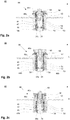
- the handle 44 in detail drawings in the Figures 2a, 2b and 2c shown.
- the handle 44 has a cylindrical bearing body 46, on the outer wall, a wall 48 is slidably disposed in the axial direction.
- two rocker arms 50 with respect to the rotor axis R are arranged opposite one another.
- the longitudinal extension of the rocker arm 50 is substantially aligned axially.
- the cross section of the rocker arm 50 has approximately centrally to the bearing body 46 facing toward thickening 52, which is rounded. Through these thickenings 52 in each case one of the better clarity, not shown strut 54, over which the rocker arm 50 is tilted.
- the strut 54 thus forms with the associated recess in the thickening 52 a tilting joint for the rocker arm relative to the bearing body 46 and this at least partially completely surrounding wall 48.
- actuator 56 extends to the Rocker arm 50.
- the cross section of the rocker arm 50 tapers towards the upper end respectively.
- the cross section of the rocker arm 50 likewise tapers in each case.
- the actuators 56 are each associated with a recess 46a in the bearing body 46 and a recess 48a in the wall 48, through which the actuators 56 partially projecting laterally out of the handle 44.
- each rocker arm 50 At the upper end of each rocker arm 50, a recess 60 is provided in each case, in which one end of a along the bearing body 46 of the handle 44 arranged spring 62, in particular leaf spring, engages.
- the springs 62 are clamped at their ends remote from the recesses 60 with the bearing body 46 and biased radially outward. Therefore, the upper ends of the rocker arms 50 are urged radially outwards by the spring 62 when, as in FIG Fig. 2a shown no manual application of force from the outside, and come into contact with the bearing body 46, and the actuating elements 56 protrude laterally out of the handle 44 maximum.
- Fig. 2b is the handle 44 with the rocker arms 50 in the identical position as in Fig. 2a , the locking position, shown.
- the wall 48 of the handle 44 is displaced axially relative to the bearing body 46 in the removal direction E.
- This relative change in position of the wall 48 relative to the bearing body 46 takes place when an operator grips the handle 44 and raises without loosening the lock between the cover 40 and the rotor 10 so that it does not act on the actuating elements 56 and thereby force the rocker arms 50 tilts and removes the locking elements 58 from the introduced into the outer contour 34a of the rotor pin 34 groove 34b.
- the wall 48 is acted upon by one of the better clarity, not shown spring acting against the withdrawal direction E force. As soon as the operator turns off the rotor 10 or inserts it into a centrifuge 100 and thus neutralizes the weight applied to the handle 44, the wall 48 returns to its original position and the blocking of the rocker arms 50 by the projection 48b is released. The projection 48b of the wall 48 thus forms a securing element which blocks or releases an actuation of the rocker arm 50 as needed, depending on the position in which it is located.
- FIG. 2c the wall 48 of the handle 44 is shown again in its initial position.
- the projection 48b is again below the rocker arm 50, whereby the in Fig. 2b shown Blocking of the rocker arm 50 is eliminated.
- the rocker arms 50 are tilted due to manual application of force to the actuators 56 about their tilting joints formed by strut 54 and associated recess 52 in the thickening, and the locking elements 58 are located outside the groove 34b. The lock between the rotor 10 and cover 40 is released, and the lid 40 can be removed from the rotor 10.
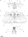
- Fig. 3 shows a side sectional view of the rotor 10 - with respect to the Fig. 1 and the Fig. 2a to 2c again rotated by 90 ° - in exploded view with removed cover 40 and a support 106 of a centrifuge 100, as shown schematically in Fig. 6 is shown.
- the closure ball 22 engages when placing the rotor 10 on the bearing 106 of the centrifuge 100 in an opening 110 of a concentrically arranged on the support 106 and bolted to the support 106 abutment insert 108 a.
- the opening 110 is sized so that the closure ball 22 can pass with minimal play.
- the opening 110 is adjoined by an inner contour 112 of the abutment insert 108 that widens conically against the removal direction E.
- a spring 24 is arranged, in which a for clarity in FIG. 3b separately shown blocking unit 26 is mounted and acted upon in withdrawal direction E acting spring force.
- the blocking unit 26 has four locking springs 30 connected via a connecting ring 28, at the end of which a blocking element 30a is attached.
- the locking elements 30a are adapted in shape substantially to the outer contour of the closure ball 22.
- the locking elements 30a and thus the entire locking unit 26 are first pressed by the penetrating through the opening 110 closure ball 22 down, in the region of the inner contour 112 in the abutment insert 108 which is larger than that Opening 110, so that the locking elements 30a can now be pushed apart.
- the blocking elements 30a then slide along the closure ball 22 until they finally engage around the closure ball 22 when the rotor 10 is fully seated on the support 106.
- the locking unit 30 moves through the spring force again in removal direction E, and the locking elements 30a come to the inner contour 112 of the abutment insert 108 in abutment.
- the circumference of the closing ball 22 with the blocking elements 30a increases so that passing through the opening 110 of the abutment insert 108 is no longer possible.
- the blocking elements 30a can pass through the plant on the inner contour 112 of the abutment insert 108 no longer move in the radial direction.
- the rotor 10 is thus securely fixed in the axial direction on the support 106 of the centrifuge 100.
- the closure ball 22 is penetrated by a bore 32.
- the bore 32 extends from the closure ball 22 through the rotor head 12 and the adjoining rotor pin 34 therethrough.
- the inner diameter of the bore 32 widens in removal direction E at a first shoulder 32a and again at a second shoulder 32b.
- a Entriegelungsdorn 36 Through the bore 32 engages a Entriegelungsdorn 36, which in turn has a first paragraph 32a of the bore 32 associated first paragraph 36a and the second paragraph 32b of the bore 32 associated second paragraph 36b.
- Fig. 3 Marked with III a region in which the introduced into the bore 32 Entriegelungsdorn 36 is shown enlarged in Fig. 3a shown.
- the mutually associated regions of the diameter of the Entriegelungsdorns 36 and the inner diameter of the bore 32 are adapted to each other so that the Entriegelungsdorn 36 in the bore 32 is axially displaceable.
- An axial movement of the Entriegelungsdorns 36 in the direction of the support 106 is limited and possible up to an end position at which the corresponding paragraphs 32a and 36a and the paragraphs 32b and 36b each come into contact with each other.
- the longitudinal extension of the unlocking mandrel 36 is dimensioned so that a free end 38 against the withdrawal direction E emerges from the closure ball 22 when moving the Entriegelungsdorns 36, engages in the locking unit 26 and the locking unit 26 against the force applied by the spring 24 increasingly displaces, also the locking elements 30a slide along the locking ball 22 in the region of the inner contour 112, which is wider than the opening 110 of the abutment insert 108, so that the locking elements 30a can bend outward.
- the blocking unit 26 Upon reaching the above-described end position of the unlocking mandrel 36, the blocking unit 26 is shifted by a distance s s far enough that the locking elements 30a completely release the locking ball 22, ie the locking elements 30a bend radially outwards when the locking ball 22 passes the locking elements 30a.
- the closure ball 22 can now again pass through the opening 110 of the abutment insert 108, and the rotor 10 can be removed from the abutment 106 of the centrifuge 100.
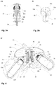
- an actuating pin 74 is provided in the handle 44, which forms an activation element 36, 74 together with the unlocking mandrel 36.
- a bearing insert 70 is introduced, which terminates flush on the side facing away from the rotor 10 side with the gripping pieces 45.
- An axial bore 72 passes through the bearing insert 70 and tapers stepwise at the end facing the rotor 10, so that an opening 72a is formed there whose diameter is less than the diameter of the bore 72.
- the actuating pin 74 is slidably mounted in the bore 72 and comprises a cylindrical first portion 76, whose diameter is adapted to the inner diameter of the bore 72, and a cylindrical second portion 78, whose diameter is adapted to the inner diameter of the opening 72 a.
- the second section 78 passes through the opening 72a and engages in a laterally limited by the bearing body 46 interior 47 of the handle 44 a.
- a formed between the first portion 76 and the second portion 78 paragraph 80 serves as a limitation for an axial displacement of the actuating pin 74 against the withdrawal direction E in an end position.
- the free end of the first portion 76 is formed as a push button 82 which protrudes completely out of the bearing insert 70 in the non-actuated state and has a height h D.
- the push button 82 Upon complete actuation of the push button 82, the push button 82 is flush with the exposed side of the bearing insert 70, and the actuating pin 74 is moved against the withdrawal direction E by a distance s B , which corresponds to the height h D. The actuating pin 74 thereby enters the previously described end position.
- the unlocking mandrel 36 and the actuating pin 74 are dimensioned in their length so that their ends facing each other in fully attached to the rotor 10 cover 40 in abutment come together.
- the unlocking mandrel 36 and the actuating pin 74 together form an activation element 36,74, by means of which the locking unit 26 axially displaced by the distance ss in a release position even with the cover 40 and the lock between the rotor 10 and shaft 104 can be deactivated as described above so that the rotor 10 can be removed from the support 106.
- the height h D of the push button 82 in the present embodiment has the same length as the distance s B and the distance s S.
- the push button 82 may also be formed higher, so that it protrudes from the bearing insert 70 in the activated state. However, the amount must not or only insignificantly h D s the length of track B and S s, otherwise the force required to release stroke of the locking unit 26 is no longer achieved and a release is no longer guaranteed.
- the activation element 36, 74 it is also possible to form the activation element 36, 74 in one piece and to store either in the handle 44 of the lid 40 or in the receiving space 18 of the rotor 10, in the rotor pin 34. If the activation element 36, 74 is mounted in the handle 44, the rotor pin 34 can be made more space-saving, or it can even be almost completely dispensed with the rotor pin 34.
- FIG. 4 As shown in perspective view, it can be seen how the locking mechanism 50, 34b for locking lid 40 and rotor and the locking device 22, 24, 26 for fixing the rotor 10 on the drive shaft 104 in the handle 44 are integrated. Conveniently, the two releases can be operated by the operator with just one hand, without significantly changing the position of the hand. As to unlock the locking device which fixes the rotor 10 on the shaft 104, a vertical pressure movement on the push button 82 is required, while the unlocking of the device which fixes the lid 40 on the rotor 10, on both sides horizontal pressure on the two actuators 56, the risk of incorrect operation is low.
- FIGS. 5a, 5b and 5c show analogous to the Figures 2a, 2b and 2c Detailed drawings of the introduced into the lid 40 handle 44 with an additional securing device, by the access state in the activated state is prevented to the locking element 50.
- the locking of the lid 40 is carried out as already described on the rocker arm 50.
- a latching element 58 is arranged, which engages in the locked state of the cover 40 in the provided in the rotor pin 34 groove 34a.
- the cover 40 is fixed axially on the rotor pin 34 and thus locked to the rotor 10.
- the rocker arms 50 are tiltably mounted on the struts 54. By a force applied to the arranged at the upper end of the rocker arm 50 actuators 56 in the direction of the rotor axis R, the rocker arm 50 are tilted to unlock so that the locking elements 58 slide out of the groove 34a and the determination of the lid 40 is released on the rotor pin 34.
- the activation of the securing of the locking takes place by lifting the handle 44.
- the wall 48 and arranged on the wall 48 projections 48b are axially displaced in the withdrawal direction E.
- a projection 48b comes into abutment with its associated rocker arm 50, so that the movement of the rocker arm 50 is blocked.
- the locking element 58 is fixed in the groove 34b, and the locking of the cover 40 and the rotor 10 is secured.
- cover 48c Arranged at the free end of the wall 48 of the rotor axis R facing away cover 48c have, together with the wall 48 of the handle 44 has an upwardly open U-shaped cross-section.
- the cover 48c are dimensioned so that their upwardly facing free ends reach below the actuators 56 when the handle 44 is in the unactuated starting position, as in Fig. 5a shown.
- the actuators 56 are freely accessible.
- FIG. 5b the rocker arms 50 are in the identical position as in FIG Fig. 5a , the locking position, shown.
- the wall 48 of the handle 44 together with the projections 48b and cover elements 48c is displaced axially relative to the bearing body 46 in the removal direction E.
- the actuators 56 each intervene in the area between the cover 48c and wall 48, so that their free ends are no longer accessible and manual application of force by an operator and thus releasing the locking of the lid 40 and Rotor 10 is prevented.
- the lock is secured both by blocking the movement of the rocker arm 50 and by a cover of the actuators Ab 56 against incorrect operation.
- Fig. 6 shows a side sectional view of a centrifuge 100 according to the invention, is omitted for clarity in the representation of a housing and a bottom.
- FIGS. 1 to 4 described rotor 10 as already in connection with Fig. 3 is connected via the support 106 with the drive shaft 104 and rotated about the rotor axis R.
- the drive shaft 104 is driven by the underlying motor 102.
- the rotor 10 is surrounded by a safety boiler 116.
- the engine 102 engages the safety boiler 116 through an opening 116a.
- a centrifuge lid 118 is provided, which is connected to the housing, not shown, in a conventional manner and the centrifuge 100 closes at its top.
Landscapes
- Centrifugal Separators (AREA)
Claims (22)
- Rotor (10) d'une centrifugeuse (100), comprenant un espace de logement (18) pour des échantillons à centrifuger, un siège (20) agencé de manière concentrique, qui est associé à un support (106) d'un arbre d'entraînement (104) de la centrifugeuse (100), un couvercle (40), qui délimite l'espace de logement (18) vers le haut et est agencé de manière concentrique par rapport au rotor et présente sur sa face située à distance de l'espace de logement (18) une poignée (44) destinée à porter le rotor et le couvercle (40), et un mécanisme de verrouillage (50, 34b) du couvercle (40) et du rotor, le mécanisme de verrouillage (50, 34b) comprenant un élément de verrouillage (50) mobile entre une position de verrouillage et une position de déverrouillage, caractérisé en ce que la poignée (44) est en partie mobile et est en liaison fonctionnelle avec un élément de fixation (48b, 48c), l'élément de fixation (48b, 48c) pouvant être déplacé au moyen de la poignée (44) entre une première position, dans laquelle l'actionnement de l'élément de verrouillage (50) est empêché, et une deuxième position libérant l'élément de verrouillage (50).
- Rotor selon la revendication 1, caractérisé en ce que l'élément de fixation (48b, 48c) est réalisé sous la forme d'un élément de recouvrement (48c), lequel, dans l'état activé, empêche un accès à l'élément de verrouillage (50), et/ou en ce que l'élément de fixation (48b, 48c) est réalisé sous la forme d'un élément de blocage (48b) lequel, dans l'état activé, immobilise l'élément de verrouillage (50) dans la position de verrouillage.
- Rotor selon la revendication 1 ou 2, caractérisé en ce que le couvercle (40) comprend un appui (52, 54) pour l'élément de verrouillage (50).
- Rotor selon la revendication 3, caractérisé en ce que l'appui (52, 54) est introduit dans un corps d'appui (46), en particulier sous forme d'un cylindre, agencé de manière concentrique par rapport au couvercle (40) et relié solidement au couvercle (40).
- Rotor selon la revendication 4, caractérisé en ce que la poignée (44) est agencée de manière concentrique par rapport au corps d'appui (46) et montée mobile par rapport au corps d'appui (46).
- Rotor selon la revendication 4 ou 5, caractérisé en ce que la poignée (44) est réalisée d'une seule pièce avec l'élément de blocage (48b) activable, la poignée (44) étant mobile avec l'élément de blocage (48b) par rapport au corps d'appui (46) entre une première position bloquant l'élément de verrouillage (50) dans la position de verrouillage et une deuxième position libérant l'élément de verrouillage (50), l'élément de verrouillage (50) ne pouvant être déplacé de la position de verrouillage dans la position de déverrouillage que dans la deuxième position.
- Rotor selon l'une quelconque des revendications 4 à 6, caractérisé en ce qu'un coulissement de la poignée (44) est réalisé sur le corps d'appui (46) le long de l'axe de rotor (R) de la première position vers la deuxième position et vice versa.
- Rotor selon l'une quelconque des revendications 4 à 7, caractérisé en ce qu'un déplacement de la poignée (44) avec l'élément de blocage (48b) à distance du couvercle (40) correspond à un déplacement dans la première position et un déplacement de la poignée (44) avec l'élément de blocage (48b) en direction du couvercle (40) correspond à un déplacement dans la deuxième position.
- Rotor selon la revendication 8, caractérisé en ce que la poignée (44) est sollicitée par un ressort en direction du couvercle (40).
- Rotor selon l'une quelconque des revendications précédentes, caractérisé en ce que le mécanisme de verrouillage (50, 34b) traverse par endroits, en particulier latéralement, la poignée (44).
- Rotor selon l'une quelconque des revendications précédentes, caractérisé en ce que l'élément de verrouillage (50) est un culbuteur.
- Rotor selon la revendication 11, caractérisé en ce que le culbuteur (50) est sollicité par un ressort en direction de la position de verrouillage.
- Rotor selon l'une quelconque des revendications 11 ou 12, caractérisé en ce que l'extrémité inférieure du culbuteur (50) est réalisée sous la forme d'un élément d'encliquetage (58), lequel, dans la position de verrouillage, s'insère dans une rainure (34b) ménagée dans le rotor et ouverte en direction de l'espace de logement (18), et le culbuteur (50) peut être libéré de la position de verrouillage à la suite d'une pression exercée sur l'extrémité supérieure du culbuteur (50).
- Rotor selon l'une quelconque des revendications précédentes, caractérisé en ce qu'un dispositif d'arrêt (22, 24, 26) est destiné à immobiliser le rotor par rapport à l'arbre d'entraînement (104) de la centrifugeuse (100), un élément d'activation (74, 36) destiné à activer le dispositif d'arrêt (22, 24, 26) et accessible lorsque le couvercle (40) est appliqué étant monté dans le couvercle (40).
- Rotor selon la revendication 14, caractérisé en ce que le dispositif d'arrêt (22, 24, 26) comprend une unité d'arrêt (26) qui peut se déplacer au moyen de l'élément d'activation (74, 36) entre une position d'arrêt et une position de libération.
- Rotor selon la revendication 15, caractérisé en ce que l'unité d'arrêt (26) est sollicitée par un ressort en direction de la position d'arrêt.
- Rotor selon l'une quelconque des revendications 15 ou 16, caractérisé en ce que l'élément d'activation (74, 36) peut être actionné dans une direction parallèle à l'axe de rotor (R).
- Rotor selon l'une quelconque des revendications 14 à 17, caractérisé en ce que l'élément d'activation (74, 36) est monté par endroits dans la poignée (44) du couvercle (40).
- Rotor selon l'une quelconque des revendications 15 à 18, caractérisé en ce qu'un bouton-poussoir (82) est prévu à l'extrémité de l'élément d'activation (74, 36) éloignée de l'unité d'arrêt (26) et se situe, au moins dans la position d'arrêt de l'élément d'activation (74, 36), à l'extérieur de la poignée (44).
- Centrifugeuse (100) comprenant un entraînement, un arbre d'entraînement (104) à l'extrémité libre duquel est situé un support (106) sur lequel un rotor (10) selon l'une quelconque des revendications précédentes est en appui avec son siège (20).
- Centrifugeuse selon la revendication 20, caractérisée en ce que le dispositif d'arrêt (22, 24, 26) comprend un corps d'arrêt (22), qui coopère avec l'unité d'arrêt (26) et immobilise ainsi le rotor (10) par rapport à l'arbre d'entraînement (104).
- Centrifugeuse selon la revendication 21, caractérisée en ce que le corps d'arrêt (22) est agencé sur le siège (20) du rotor, s'insère au moins par endroits dans le support (106) en passant par un évidement (110) ménagé dans le support (106), et est ainsi enserré dans la position d'arrêt par l'unité d'arrêt (26), de sorte que la périphérie extérieure de l'unité d'arrêt (26) enserrant le corps d'arrêt (22) est plus grande que la périphérie intérieure de l'évidement (110).
Applications Claiming Priority (1)
| Application Number | Priority Date | Filing Date | Title |
|---|---|---|---|
| DE102015113855.7A DE102015113855A1 (de) | 2015-08-20 | 2015-08-20 | Rotor einer Zentrifuge |
Publications (2)
| Publication Number | Publication Date |
|---|---|
| EP3132855A1 EP3132855A1 (fr) | 2017-02-22 |
| EP3132855B1 true EP3132855B1 (fr) | 2018-04-18 |
Family
ID=56609798
Family Applications (1)
| Application Number | Title | Priority Date | Filing Date |
|---|---|---|---|
| EP16183169.8A Active EP3132855B1 (fr) | 2015-08-20 | 2016-08-08 | Rotor d'une centrifugeuse |
Country Status (4)
| Country | Link |
|---|---|
| US (1) | US10486170B2 (fr) |
| EP (1) | EP3132855B1 (fr) |
| CN (1) | CN106944266B (fr) |
| DE (1) | DE102015113855A1 (fr) |
Cited By (1)
| Publication number | Priority date | Publication date | Assignee | Title |
|---|---|---|---|---|
| US11731144B2 (en) | 2017-12-20 | 2023-08-22 | Eppendorf Se | Centrifuge rotor with locking levers providing visual indication of cover closure |
Families Citing this family (10)
| Publication number | Priority date | Publication date | Assignee | Title |
|---|---|---|---|---|
| DE102013107681B4 (de) * | 2013-07-18 | 2018-02-08 | Andreas Hettich Gmbh & Co. Kg | Zentrifuge |
| DE102014112501B4 (de) * | 2014-08-29 | 2017-07-27 | Andreas Hettich Gmbh & Co. Kg | Zentrifuge |
| DE102015113854A1 (de) * | 2015-08-20 | 2017-02-23 | Andreas Hettich Gmbh & Co. Kg | Rotor einer Zentrifuge |
| DE102015113855A1 (de) * | 2015-08-20 | 2017-02-23 | Andreas Hettich Gmbh & Co. Kg | Rotor einer Zentrifuge |
| CN107621395B (zh) * | 2017-09-28 | 2022-03-15 | 中国人民解放军军事医学科学院放射与辐射医学研究所 | 一种混匀-离心一体化转子 |
| JP1619045S (fr) * | 2018-03-09 | 2018-11-26 | ||
| CN108501276A (zh) * | 2018-03-14 | 2018-09-07 | 南方电网科学研究院有限责任公司 | 离心机转子和制造绝缘件的离心机转子、方法 |
| DE102018114289A1 (de) * | 2018-06-14 | 2019-12-19 | Andreas Hettich Gmbh & Co. Kg | Zentrifuge |
| EP4180131A1 (fr) * | 2021-11-11 | 2023-05-17 | Eppendorf SE | Rotor centrifuge, couvercle de rotor et partie inférieure de rotor |
| CN114950746B (zh) * | 2022-07-27 | 2022-12-06 | 深圳市瑞沃德生命科技有限公司 | 一种转子及具有其的离心机 |
Family Cites Families (45)
| Publication number | Priority date | Publication date | Assignee | Title |
|---|---|---|---|---|
| US2329499A (en) * | 1942-03-18 | 1943-09-14 | American Viscose Corp | Spinning box |
| US2827229A (en) * | 1953-08-26 | 1958-03-18 | Sorvall Inc Ivan | Centrifuge mounting means |
| US2865662A (en) * | 1954-09-10 | 1958-12-23 | Urfabriken Ab | Means for removably mounting a member on a shaft |
| US3819111A (en) * | 1973-04-09 | 1974-06-25 | Sorvall Inc Ivan | Centrifuge rotor cover |
| US3901434A (en) | 1973-10-10 | 1975-08-26 | Beckman Instruments Inc | Non-extruding lid seal for centrifuges |
| US3961745A (en) * | 1974-04-08 | 1976-06-08 | Beckman Instruments, Inc. | Centrifuge apparatus |
| DE2722322C3 (de) * | 1977-05-17 | 1981-08-27 | Compur-Electronic GmbH, 8000 München | Zentrifuge zum Trennen von Probenflüssigkeiten in röhrchenförmigen Behältern |
| WO1983004379A1 (fr) * | 1982-06-09 | 1983-12-22 | Beckman Instruments, Inc. | Assemblage d'attache d'un rotor de centrifugeuse |
| US4412830A (en) * | 1982-06-24 | 1983-11-01 | Beckman Instruments, Inc. | Cover for centrifuge rotor |
| US4435169A (en) * | 1982-09-29 | 1984-03-06 | E. I. Du Pont De Nemours And Company | Centrifuge rotor having a closable windshield |
| US4753631A (en) * | 1986-11-03 | 1988-06-28 | E. I. Du Pont De Nemours And Company | Speed limiting arrangement for a centrifuge rotor having an axial mounting bolt |
| US4822331A (en) * | 1987-11-09 | 1989-04-18 | Taylor David C | Centrifuge |
| EP0611328A1 (fr) * | 1991-10-21 | 1994-08-24 | Beckman Instruments, Inc. | Recipient hybride contenant des porte-echantillons dans une centrifugeuse |
| FR2694509B1 (fr) * | 1992-08-04 | 1994-10-07 | Jouan | Centrifugeur comportant un arbre d'entraînement de rotor à joint élastique d'amortissement et arbre correspondant. |
| US5344380A (en) * | 1992-09-30 | 1994-09-06 | Beckman Instruments, Inc. | Release handle for centrifuge rotor and lid |
| DE9301663U1 (de) * | 1993-02-06 | 1993-10-07 | Fa. Andreas Hettich, 78532 Tuttlingen | Deckelverschluß |
| WO1995034382A1 (fr) * | 1994-06-15 | 1995-12-21 | Massachusetts Institute Of Technology | Ensemble formant element de recouvrement de rotor de centrifuge a verrouillage |
| FR2727037A1 (fr) * | 1994-11-21 | 1996-05-24 | Jouan | Centrifugeuse a rotor demontable et a dispositif de blocage axial du rotor sur l'arbre d'entrainement |
| FR2770154B1 (fr) * | 1997-10-23 | 1999-11-26 | Jouan | Centrifugeuse a rotor demontable et a dispositif de blocage axial du rotor sur une tete d'entrainement, et rotor pour une telle centrifugeuse |
| US5897482A (en) * | 1998-03-04 | 1999-04-27 | Beckman Instruments, Inc. | Rotor lid tie-down and vacuum venting system |
| JP3861476B2 (ja) * | 1998-09-30 | 2006-12-20 | 日立工機株式会社 | 遠心分離機 |
| US6149570A (en) * | 1999-02-23 | 2000-11-21 | Beckman Coulter, Inc. | Self-retaining rotor lid |
| CN2489873Y (zh) | 2001-07-26 | 2002-05-08 | 长沙三德实业有限公司 | 医用离心机转子识别机构 |
| US6665924B2 (en) * | 2002-01-25 | 2003-12-23 | Kendro Laboratory Products, L.P. | Centrifuge having a spring-loaded nut for securing a rotor to a drive cone |
| US7081081B2 (en) * | 2002-04-22 | 2006-07-25 | Kendro Laboratory Products, Lp | Bayonet coupling mechanism for a centrifuge |
| US6776751B2 (en) * | 2002-04-22 | 2004-08-17 | Kendor Laboratory Products, Lp | Rotor cover attachment apparatus |
| US6802803B2 (en) * | 2002-04-22 | 2004-10-12 | Kendro Laboratory Products, Inc. | Cover attachment apparatus |
| US6764438B2 (en) * | 2002-04-22 | 2004-07-20 | Kendro Laboratory Products, Lp | Cover attachment apparatus |
| US7011618B2 (en) * | 2003-05-16 | 2006-03-14 | Kendro Laboratory Products Lp | Attachment and release apparatus for a centrifuge rotor cover |
| JP4546794B2 (ja) * | 2004-09-15 | 2010-09-15 | トミー工業株式会社 | 遠心分離機のロータ取付け構造 |
| DE102005014218B4 (de) * | 2005-03-29 | 2008-03-06 | Thermo Electron Led Gmbh | Befestigungsvorrichtung eines Deckels für einen Zentrifugenrotor |
| US7837607B2 (en) * | 2006-12-13 | 2010-11-23 | Thermo Fisher Scientific Inc. | Centrifuge rotor assembly and method of connection thereof |
| DE102008045556A1 (de) * | 2008-09-03 | 2010-03-04 | Thermo Electron Led Gmbh | Zentrifuge mit einem Kupplungselement zur axialen Verriegelung eines Rotors |
| DE202010014803U1 (de) * | 2010-11-01 | 2010-12-30 | Sigma Laborzentrifugen Gmbh | Rotorlagerung für eine Laborzentrifuge |
| DE102012011531B4 (de) * | 2012-06-08 | 2016-11-10 | Thermo Electron Led Gmbh | Set aus Antriebskopf und Nabe zur lösbaren Verbindung eines Antriebes mit einem Rotor einer Zentrifuge für einen weiten Drehzahlbereich |
| FR3005273A1 (fr) * | 2013-05-02 | 2014-11-07 | Afi Centrifuge | Centrifugeuse de laboratoire comprenant des moyens pour le verrouillage en translation d'un rotor sur un arbre moteur d'entrainement |
| DE102013107681B4 (de) * | 2013-07-18 | 2018-02-08 | Andreas Hettich Gmbh & Co. Kg | Zentrifuge |
| US9585929B2 (en) | 2014-07-18 | 2017-03-07 | Zhejiang Kanglaite Group Co., Ltd. | Coix seed oil containing 13 glycerides, and pharmaceutical preparation and use thereof |
| DE102014112501B4 (de) * | 2014-08-29 | 2017-07-27 | Andreas Hettich Gmbh & Co. Kg | Zentrifuge |
| EP3012027B1 (fr) * | 2014-10-21 | 2016-09-21 | Sigma Laborzentrifugen GmbH | Ensemble d'embrayage actionné par la force centrifuge pour une centrifugeuse de laboratoire |
| DE102015113855A1 (de) * | 2015-08-20 | 2017-02-23 | Andreas Hettich Gmbh & Co. Kg | Rotor einer Zentrifuge |
| DE102015119616A1 (de) * | 2015-11-13 | 2017-05-18 | Hengst Se & Co. Kg | Rotor eines Zentrifugalabscheiders |
| CN205323999U (zh) | 2015-12-31 | 2016-06-22 | 广州国睿科学仪器有限公司 | 一种离心机转子固定结构 |
| DE102017130787A1 (de) * | 2017-12-20 | 2019-06-27 | Eppendorf Ag | Zentrifugenrotor |
| DE102017130786A1 (de) * | 2017-12-20 | 2019-06-27 | Eppendorf Ag | Zentrifugenrotor |
-
2015
- 2015-08-20 DE DE102015113855.7A patent/DE102015113855A1/de active Pending
-
2016
- 2016-08-08 EP EP16183169.8A patent/EP3132855B1/fr active Active
- 2016-08-19 US US15/242,006 patent/US10486170B2/en active Active
- 2016-08-22 CN CN201610803938.6A patent/CN106944266B/zh active Active
Non-Patent Citations (1)
| Title |
|---|
| None * |
Cited By (1)
| Publication number | Priority date | Publication date | Assignee | Title |
|---|---|---|---|---|
| US11731144B2 (en) | 2017-12-20 | 2023-08-22 | Eppendorf Se | Centrifuge rotor with locking levers providing visual indication of cover closure |
Also Published As
| Publication number | Publication date |
|---|---|
| US20170050195A1 (en) | 2017-02-23 |
| CN106944266B (zh) | 2019-05-14 |
| DE102015113855A1 (de) | 2017-02-23 |
| US10486170B2 (en) | 2019-11-26 |
| CN106944266A (zh) | 2017-07-14 |
| EP3132855A1 (fr) | 2017-02-22 |
Similar Documents
| Publication | Publication Date | Title |
|---|---|---|
| EP3132855B1 (fr) | Rotor d'une centrifugeuse | |
| EP3132854B1 (fr) | Rotor d'une centrifugeuse | |
| EP3021974B1 (fr) | Centrifugeuse | |
| EP1344494B1 (fr) | Appareil de visée pour clou verrouillable | |
| EP3186009B1 (fr) | Fermeture rapide d'une centrifugeuse | |
| EP1371455B1 (fr) | Dispositif d'accouplement pour verrouiller une connexion à fiches d'un outil | |
| EP3615749B1 (fr) | Ferrure pour fênetre ou porte | |
| EP0732892B1 (fr) | Instrument chirurgical tubulaire | |
| EP3263202B1 (fr) | Système de prélèvement et aide au prélèvement pour un élément de séparation | |
| EP1997590B1 (fr) | Appareil de pose manuel doté d'un raccordement pour un dispositif de positionnement | |
| DE102006005572A1 (de) | Stanzvorrichtung | |
| WO2006125653A1 (fr) | Liaison entre deux parties d'outil | |
| DE19806790B4 (de) | Vorrichtung an einem Betätigungsorgan, insbesondere einer Türgriffanordnung an einem Kraftfahrzeug | |
| EP4162188A1 (fr) | Dispositif pour relier deux objets tubulaires | |
| EP3065978B1 (fr) | Antivol de direction pour colonne de direction pour véhicule automobile | |
| EP3669992A1 (fr) | Construction de connexion | |
| DE19541214C1 (de) | Drehbetätigungseinrichtung | |
| DE102015113856A1 (de) | Rotor einer Zentrifuge | |
| EP2873634A1 (fr) | Cartouche de courrier par tube | |
| DE202018005796U1 (de) | Verbindungskonstruktion | |
| EP0654246A1 (fr) | Instrument médical avec tige centrale de travail et poignée | |
| DE102016112788A1 (de) | Medizinische Werkzeugvorrichtung | |
| EP3109004B1 (fr) | Dispositif de montage | |
| EP2682353B1 (fr) | Tête de pulvérisation d'un atomiseur | |
| EP1574293B1 (fr) | Articulation glissante |
Legal Events
| Date | Code | Title | Description |
|---|---|---|---|
| PUAI | Public reference made under article 153(3) epc to a published international application that has entered the european phase |
Free format text: ORIGINAL CODE: 0009012 |
|
| AK | Designated contracting states |
Kind code of ref document: A1 Designated state(s): AL AT BE BG CH CY CZ DE DK EE ES FI FR GB GR HR HU IE IS IT LI LT LU LV MC MK MT NL NO PL PT RO RS SE SI SK SM TR |
|
| AX | Request for extension of the european patent |
Extension state: BA ME |
|
| 17P | Request for examination filed |
Effective date: 20170522 |
|
| RBV | Designated contracting states (corrected) |
Designated state(s): AL AT BE BG CH CY CZ DE DK EE ES FI FR GB GR HR HU IE IS IT LI LT LU LV MC MK MT NL NO PL PT RO RS SE SI SK SM TR |
|
| RIC1 | Information provided on ipc code assigned before grant |
Ipc: B04B 7/02 20060101ALI20170925BHEP Ipc: B04B 7/06 20060101ALI20170925BHEP Ipc: B04B 5/04 20060101AFI20170925BHEP Ipc: B04B 7/08 20060101ALI20170925BHEP |
|
| GRAP | Despatch of communication of intention to grant a patent |
Free format text: ORIGINAL CODE: EPIDOSNIGR1 |
|
| INTG | Intention to grant announced |
Effective date: 20171106 |
|
| GRAS | Grant fee paid |
Free format text: ORIGINAL CODE: EPIDOSNIGR3 |
|
| GRAA | (expected) grant |
Free format text: ORIGINAL CODE: 0009210 |
|
| AK | Designated contracting states |
Kind code of ref document: B1 Designated state(s): AL AT BE BG CH CY CZ DE DK EE ES FI FR GB GR HR HU IE IS IT LI LT LU LV MC MK MT NL NO PL PT RO RS SE SI SK SM TR |
|
| REG | Reference to a national code |
Ref country code: GB Ref legal event code: FG4D Free format text: NOT ENGLISH |
|
| REG | Reference to a national code |
Ref country code: CH Ref legal event code: EP |
|
| REG | Reference to a national code |
Ref country code: AT Ref legal event code: REF Ref document number: 989867 Country of ref document: AT Kind code of ref document: T Effective date: 20180515 |
|
| REG | Reference to a national code |
Ref country code: IE Ref legal event code: FG4D Free format text: LANGUAGE OF EP DOCUMENT: GERMAN |
|
| REG | Reference to a national code |
Ref country code: DE Ref legal event code: R096 Ref document number: 502016000912 Country of ref document: DE |
|
| REG | Reference to a national code |
Ref country code: NL Ref legal event code: MP Effective date: 20180418 |
|
| REG | Reference to a national code |
Ref country code: LT Ref legal event code: MG4D |
|
| PG25 | Lapsed in a contracting state [announced via postgrant information from national office to epo] |
Ref country code: NL Free format text: LAPSE BECAUSE OF FAILURE TO SUBMIT A TRANSLATION OF THE DESCRIPTION OR TO PAY THE FEE WITHIN THE PRESCRIBED TIME-LIMIT Effective date: 20180418 |
|
| PG25 | Lapsed in a contracting state [announced via postgrant information from national office to epo] |
Ref country code: NO Free format text: LAPSE BECAUSE OF FAILURE TO SUBMIT A TRANSLATION OF THE DESCRIPTION OR TO PAY THE FEE WITHIN THE PRESCRIBED TIME-LIMIT Effective date: 20180718 Ref country code: AL Free format text: LAPSE BECAUSE OF FAILURE TO SUBMIT A TRANSLATION OF THE DESCRIPTION OR TO PAY THE FEE WITHIN THE PRESCRIBED TIME-LIMIT Effective date: 20180418 Ref country code: FI Free format text: LAPSE BECAUSE OF FAILURE TO SUBMIT A TRANSLATION OF THE DESCRIPTION OR TO PAY THE FEE WITHIN THE PRESCRIBED TIME-LIMIT Effective date: 20180418 Ref country code: BG Free format text: LAPSE BECAUSE OF FAILURE TO SUBMIT A TRANSLATION OF THE DESCRIPTION OR TO PAY THE FEE WITHIN THE PRESCRIBED TIME-LIMIT Effective date: 20180718 Ref country code: SE Free format text: LAPSE BECAUSE OF FAILURE TO SUBMIT A TRANSLATION OF THE DESCRIPTION OR TO PAY THE FEE WITHIN THE PRESCRIBED TIME-LIMIT Effective date: 20180418 Ref country code: PL Free format text: LAPSE BECAUSE OF FAILURE TO SUBMIT A TRANSLATION OF THE DESCRIPTION OR TO PAY THE FEE WITHIN THE PRESCRIBED TIME-LIMIT Effective date: 20180418 Ref country code: ES Free format text: LAPSE BECAUSE OF FAILURE TO SUBMIT A TRANSLATION OF THE DESCRIPTION OR TO PAY THE FEE WITHIN THE PRESCRIBED TIME-LIMIT Effective date: 20180418 Ref country code: LT Free format text: LAPSE BECAUSE OF FAILURE TO SUBMIT A TRANSLATION OF THE DESCRIPTION OR TO PAY THE FEE WITHIN THE PRESCRIBED TIME-LIMIT Effective date: 20180418 |
|
| PG25 | Lapsed in a contracting state [announced via postgrant information from national office to epo] |
Ref country code: HR Free format text: LAPSE BECAUSE OF FAILURE TO SUBMIT A TRANSLATION OF THE DESCRIPTION OR TO PAY THE FEE WITHIN THE PRESCRIBED TIME-LIMIT Effective date: 20180418 Ref country code: LV Free format text: LAPSE BECAUSE OF FAILURE TO SUBMIT A TRANSLATION OF THE DESCRIPTION OR TO PAY THE FEE WITHIN THE PRESCRIBED TIME-LIMIT Effective date: 20180418 Ref country code: GR Free format text: LAPSE BECAUSE OF FAILURE TO SUBMIT A TRANSLATION OF THE DESCRIPTION OR TO PAY THE FEE WITHIN THE PRESCRIBED TIME-LIMIT Effective date: 20180719 Ref country code: RS Free format text: LAPSE BECAUSE OF FAILURE TO SUBMIT A TRANSLATION OF THE DESCRIPTION OR TO PAY THE FEE WITHIN THE PRESCRIBED TIME-LIMIT Effective date: 20180418 |
|
| REG | Reference to a national code |
Ref country code: DE Ref legal event code: R097 Ref document number: 502016000912 Country of ref document: DE |
|
| PG25 | Lapsed in a contracting state [announced via postgrant information from national office to epo] |
Ref country code: EE Free format text: LAPSE BECAUSE OF FAILURE TO SUBMIT A TRANSLATION OF THE DESCRIPTION OR TO PAY THE FEE WITHIN THE PRESCRIBED TIME-LIMIT Effective date: 20180418 Ref country code: DK Free format text: LAPSE BECAUSE OF FAILURE TO SUBMIT A TRANSLATION OF THE DESCRIPTION OR TO PAY THE FEE WITHIN THE PRESCRIBED TIME-LIMIT Effective date: 20180418 Ref country code: RO Free format text: LAPSE BECAUSE OF FAILURE TO SUBMIT A TRANSLATION OF THE DESCRIPTION OR TO PAY THE FEE WITHIN THE PRESCRIBED TIME-LIMIT Effective date: 20180418 Ref country code: CZ Free format text: LAPSE BECAUSE OF FAILURE TO SUBMIT A TRANSLATION OF THE DESCRIPTION OR TO PAY THE FEE WITHIN THE PRESCRIBED TIME-LIMIT Effective date: 20180418 Ref country code: SK Free format text: LAPSE BECAUSE OF FAILURE TO SUBMIT A TRANSLATION OF THE DESCRIPTION OR TO PAY THE FEE WITHIN THE PRESCRIBED TIME-LIMIT Effective date: 20180418 |
|
| PLBE | No opposition filed within time limit |
Free format text: ORIGINAL CODE: 0009261 |
|
| STAA | Information on the status of an ep patent application or granted ep patent |
Free format text: STATUS: NO OPPOSITION FILED WITHIN TIME LIMIT |
|
| PG25 | Lapsed in a contracting state [announced via postgrant information from national office to epo] |
Ref country code: SM Free format text: LAPSE BECAUSE OF FAILURE TO SUBMIT A TRANSLATION OF THE DESCRIPTION OR TO PAY THE FEE WITHIN THE PRESCRIBED TIME-LIMIT Effective date: 20180418 Ref country code: IT Free format text: LAPSE BECAUSE OF FAILURE TO SUBMIT A TRANSLATION OF THE DESCRIPTION OR TO PAY THE FEE WITHIN THE PRESCRIBED TIME-LIMIT Effective date: 20180418 |
|
| 26N | No opposition filed |
Effective date: 20190121 |
|
| PG25 | Lapsed in a contracting state [announced via postgrant information from national office to epo] |
Ref country code: MC Free format text: LAPSE BECAUSE OF FAILURE TO SUBMIT A TRANSLATION OF THE DESCRIPTION OR TO PAY THE FEE WITHIN THE PRESCRIBED TIME-LIMIT Effective date: 20180418 |
|
| PG25 | Lapsed in a contracting state [announced via postgrant information from national office to epo] |
Ref country code: LU Free format text: LAPSE BECAUSE OF NON-PAYMENT OF DUE FEES Effective date: 20180808 |
|
| REG | Reference to a national code |
Ref country code: BE Ref legal event code: MM Effective date: 20180831 |
|
| REG | Reference to a national code |
Ref country code: IE Ref legal event code: MM4A |
|
| PG25 | Lapsed in a contracting state [announced via postgrant information from national office to epo] |
Ref country code: SI Free format text: LAPSE BECAUSE OF FAILURE TO SUBMIT A TRANSLATION OF THE DESCRIPTION OR TO PAY THE FEE WITHIN THE PRESCRIBED TIME-LIMIT Effective date: 20180418 |
|
| PG25 | Lapsed in a contracting state [announced via postgrant information from national office to epo] |
Ref country code: IE Free format text: LAPSE BECAUSE OF NON-PAYMENT OF DUE FEES Effective date: 20180808 |
|
| PG25 | Lapsed in a contracting state [announced via postgrant information from national office to epo] |
Ref country code: FR Free format text: LAPSE BECAUSE OF NON-PAYMENT OF DUE FEES Effective date: 20180831 Ref country code: BE Free format text: LAPSE BECAUSE OF NON-PAYMENT OF DUE FEES Effective date: 20180831 |
|
| PG25 | Lapsed in a contracting state [announced via postgrant information from national office to epo] |
Ref country code: MT Free format text: LAPSE BECAUSE OF FAILURE TO SUBMIT A TRANSLATION OF THE DESCRIPTION OR TO PAY THE FEE WITHIN THE PRESCRIBED TIME-LIMIT Effective date: 20180418 |
|
| PG25 | Lapsed in a contracting state [announced via postgrant information from national office to epo] |
Ref country code: TR Free format text: LAPSE BECAUSE OF FAILURE TO SUBMIT A TRANSLATION OF THE DESCRIPTION OR TO PAY THE FEE WITHIN THE PRESCRIBED TIME-LIMIT Effective date: 20180418 |
|
| PG25 | Lapsed in a contracting state [announced via postgrant information from national office to epo] |
Ref country code: PT Free format text: LAPSE BECAUSE OF FAILURE TO SUBMIT A TRANSLATION OF THE DESCRIPTION OR TO PAY THE FEE WITHIN THE PRESCRIBED TIME-LIMIT Effective date: 20180418 Ref country code: LI Free format text: LAPSE BECAUSE OF NON-PAYMENT OF DUE FEES Effective date: 20190831 Ref country code: CH Free format text: LAPSE BECAUSE OF NON-PAYMENT OF DUE FEES Effective date: 20190831 |
|
| PG25 | Lapsed in a contracting state [announced via postgrant information from national office to epo] |
Ref country code: CY Free format text: LAPSE BECAUSE OF FAILURE TO SUBMIT A TRANSLATION OF THE DESCRIPTION OR TO PAY THE FEE WITHIN THE PRESCRIBED TIME-LIMIT Effective date: 20180418 Ref country code: HU Free format text: LAPSE BECAUSE OF FAILURE TO SUBMIT A TRANSLATION OF THE DESCRIPTION OR TO PAY THE FEE WITHIN THE PRESCRIBED TIME-LIMIT; INVALID AB INITIO Effective date: 20160808 Ref country code: MK Free format text: LAPSE BECAUSE OF NON-PAYMENT OF DUE FEES Effective date: 20180418 |
|
| PG25 | Lapsed in a contracting state [announced via postgrant information from national office to epo] |
Ref country code: IS Free format text: LAPSE BECAUSE OF FAILURE TO SUBMIT A TRANSLATION OF THE DESCRIPTION OR TO PAY THE FEE WITHIN THE PRESCRIBED TIME-LIMIT Effective date: 20180818 |
|
| GBPC | Gb: european patent ceased through non-payment of renewal fee |
Effective date: 20200808 |
|
| PG25 | Lapsed in a contracting state [announced via postgrant information from national office to epo] |
Ref country code: GB Free format text: LAPSE BECAUSE OF NON-PAYMENT OF DUE FEES Effective date: 20200808 |
|
| REG | Reference to a national code |
Ref country code: AT Ref legal event code: MM01 Ref document number: 989867 Country of ref document: AT Kind code of ref document: T Effective date: 20210808 |
|
| PG25 | Lapsed in a contracting state [announced via postgrant information from national office to epo] |
Ref country code: AT Free format text: LAPSE BECAUSE OF NON-PAYMENT OF DUE FEES Effective date: 20210808 |
|
| P01 | Opt-out of the competence of the unified patent court (upc) registered |
Effective date: 20230530 |
|
| PGFP | Annual fee paid to national office [announced via postgrant information from national office to epo] |
Ref country code: DE Payment date: 20230830 Year of fee payment: 8 |