EP1574293B1 - Articulation glissante - Google Patents
Articulation glissante Download PDFInfo
- Publication number
- EP1574293B1 EP1574293B1 EP04005989A EP04005989A EP1574293B1 EP 1574293 B1 EP1574293 B1 EP 1574293B1 EP 04005989 A EP04005989 A EP 04005989A EP 04005989 A EP04005989 A EP 04005989A EP 1574293 B1 EP1574293 B1 EP 1574293B1
- Authority
- EP
- European Patent Office
- Prior art keywords
- locking bolt
- sliding joint
- pressure spring
- shaft
- sleeve
- Prior art date
- Legal status (The legal status is an assumption and is not a legal conclusion. Google has not performed a legal analysis and makes no representation as to the accuracy of the status listed.)
- Expired - Lifetime
Links
- 230000006835 compression Effects 0.000 description 12
- 238000007906 compression Methods 0.000 description 12
- XLYOFNOQVPJJNP-UHFFFAOYSA-N water Substances O XLYOFNOQVPJJNP-UHFFFAOYSA-N 0.000 description 3
- 230000006378 damage Effects 0.000 description 2
- 208000027418 Wounds and injury Diseases 0.000 description 1
- 238000010276 construction Methods 0.000 description 1
- 230000008878 coupling Effects 0.000 description 1
- 238000010168 coupling process Methods 0.000 description 1
- 238000005859 coupling reaction Methods 0.000 description 1
- 238000005553 drilling Methods 0.000 description 1
- 230000002349 favourable effect Effects 0.000 description 1
- 238000005242 forging Methods 0.000 description 1
- 208000014674 injury Diseases 0.000 description 1
- 238000004519 manufacturing process Methods 0.000 description 1
- 239000000463 material Substances 0.000 description 1
Images


Classifications
-
- B—PERFORMING OPERATIONS; TRANSPORTING
- B25—HAND TOOLS; PORTABLE POWER-DRIVEN TOOLS; MANIPULATORS
- B25B—TOOLS OR BENCH DEVICES NOT OTHERWISE PROVIDED FOR, FOR FASTENING, CONNECTING, DISENGAGING OR HOLDING
- B25B7/00—Pliers; Other hand-held gripping tools with jaws on pivoted limbs; Details applicable generally to pivoted-limb hand tools
- B25B7/06—Joints
- B25B7/10—Joints with adjustable fulcrum
Definitions
- the invention relates to a sliding joint for a two-part tool according to the preamble of claim 1.
- Such tools are in particular pliers, for example water pump pliers, of which two main types are widespread, namely a relatively simple version with an applied joint and a more expensive version with inserted joint. Common to both types is that a contoured slot guide allows a gradual adjustment to a desired span.
- the legs are connected like a pair of scissors by means of a bolt, usually screwed to a joint. If the fitting has loosened during use, it is easily possible to jump from one position to the next larger one when applying the pliers, which can cause damage to the workpiece and / or injury to the user.
- the object of the invention is to provide a simple sliding joint, which is particularly suitable for pliers of the launched type.
- the slide joint should allow as with plugged Knopfrastzangen a locking and unlocking at the touch of a button, but require at least equally good function less manufacturing costs.
- Another object is to provide the slide joint for use with pliers including water pump pliers so that they can be adjusted quickly and safely directly on the workpiece and with always parallel jaws, without an undesirable adjustment would be possible.
- a sliding joint for a two-part tool for example for a grasping forceps
- a slider having a movable along a tool part guide flange with a two-sided flattened step body, which axially displaceably carries a locking bolt mounted in a bush, further comprising a compression spring which a push button loaded by the operation of a locking of the sliding joint can be canceled
- the invention provides according to claim 1, that the slider has a central blind hole breakthrough and that the locking pin has a shank and a cylindrical foot which rotatably in the blind hole of the step body sitting.
- such a sliding joint Apart from the push button and compression spring, which can form a common component, such a sliding joint consists of only three components, namely a slider designed as a step body, a locking pin and a socket. This simple structure has very favorable performance characteristics, so that the slide joint can be used in a variety of tools.
- the slider preferably has a two-sided flattened step body with a central blind hole breakthrough and an external thread on the narrow sides of a side facing away from the flange neck.
- the axially movable in the stage body guided locking pin has a shaft with a widened cylindrical foot which is rotatably seated in the blind hole. This one has a robust component of simple form and correspondingly high structural strength.
- the bushing can be attached to a second tool part and has on a collar on a remote internal thread, which is screwed with the approach of the stage body to stop.
- the sleeve thus secures a predetermined distance and protects the surrounding parts of it.
- a central bore in the bottom of the blind hole breakthrough leads the locking bolt shank which is connected at the end to the push button, in or with which the compression spring is supported, which has its counter bearing on the blind hole bottom and supports in each position a locking, which by Overcoming the spring force can be solved by pressing a button.
- the flange is designed in the form of a shoulder and the approach of the step body on the side facing away from the shoulder has the external thread, which can be screwed to the axial fixing of the sliding joint on the pliers limbs to stop with the internal thread of the socket on a Round hole of the second tool leg is used.
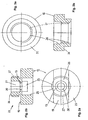
- the illustrated slide joint 10 consists of a maximum of five components: a stepped slider 12, a locking pin 14, an insert sleeve 16, a compression spring 18 and a push button 20, wherein compression spring and push button can also form a common component.
- the latching pin 14 (FIGS. 4 a, 4 b) is axially displaceably guided in the slider 12 (FIGS. 2 a, 2 b) in that a cylindrical foot 15 of the latching bolt 14 is freely rotatably arranged in a central aperture 25 of the slider 12.
- a shaft 24 of the locking bolt 14 is connected at the end to the push button 20. This is supported by the compression spring 18 at a breakthrough 25 axially delimiting bridge 13 in the slider 12, which forms the bottom of a blind hole 21.
- the slider 12 has a longitudinally movable on the slot portion A guide flange 23 and a two-sided flattened step body 22 with an external thread 27 on a side facing away from the flange 23 approach 26.
- the stage body 22 performs the axially movable locking pin 14, the widened cylindrical foot 15 merges into the shaft 24 which rotatably seated in a blind hole 21 of the step body 22.
- the insert 16 (FIG. 3 a, 3 b) is a bushing with a stepped internal thread 17 fixed to the round-hole leg B and screwing with the external thread 27 on the shoulder 26 of the step body 22.
- a central bore 30 in the bridge bottom 13 of the blind hole 21 carries the locking pin shaft 24 which is connected at the end to the push button 20 (Fig 5a, 5b), in which the compression spring 18 is supported, the abutment at the bottom of the stage body blind hole 21 has.
- Fig. 1a shows the sliding joint 10 in the locked position.
- the foot 15 of the locking bolt 14 locks the slider 12 on the slot leg A and connected to the shaft 24 of the locking bolt 14 push button 20 protrudes beyond the top of the insert sleeve 16, which is fixed to the round hole leg B to stop.
- the sliding joint 10 is a very compact combination of a maximum of five components, which is advantageously used on a two-part tool, namely a pair of pliers, to selectively bring about a clutch in the desired position or a decoupling for changing the position.
- the slider 12 has a longitudinally movable on the slot L of a tool leg A flange in the form of the shoulder 19 and a two-sided flattened step body 22, the shoulder 26 on the side facing away from the shoulder has an external thread 27.
- the step body 22 of the shaft 24 of the locking bolt 14 is guided axially movable with its widened cylindrical foot 15, namely rotatably in the central bore 30 of the blind hole 21, the bottom 13 forms an abutment for the compression spring 18, which in or on the push button 20 their other Support surface has.
Landscapes
- Engineering & Computer Science (AREA)
- Mechanical Engineering (AREA)
- Gripping Jigs, Holding Jigs, And Positioning Jigs (AREA)
- Ceramic Products (AREA)
- Electrophonic Musical Instruments (AREA)
- Mutual Connection Of Rods And Tubes (AREA)
Claims (8)
- Articulation glissante (10) pour un outil en deux pièces, par exemple pour une pince, comprenant un élément glissant (12) avec une bride de guidage (19) capable de se déplacer le long d'une pièce d'outil (A), ladite bride de guidage (19) comportant un corps étagé (22) aplati sur deux côtés qui guide les mouvements axiaux d'un boulon d'arrêt (14) logé dans une douille (16), comprenant de plus un ressort de pression (18) agissant sur un bouton-poussoir (20) qui permet, lorsqu'il est actionné, le déverrouillage de l'articulation glissante (10), caractérisée en ce que ledit élément glissant (12) comporte un percement central (25) du trou borgne, et que le boulon d'arrêt (14) a une tige (24) ainsi qu'un pied cylindrique (15), ledit pied (15) étant monté à rotation libre dans le percement (25) du trou borgne du corps étagé (22).
- Articulation glissante selon la revendication 1, caractérisée en ce que la douille (16) est pourvue, sur un collet (31), d'un filetage intérieur étagé (17) adapté pour être vissé, jusqu'à la position de butée, sur un filetage extérieur (27) sur les petits cotés d'une allonge aplatie (26) du corps étagé (22) opposée à la bride (19).
- Articulation glissante selon la revendication 1 ou 2, caractérisée en ce qu'un alésage central (30) pratiqué dans le fond (13) du percement (25) du trou borgne dans le corps étagé (22) guide les mouvements rotatifs et axiaux de la tige (24) du boulon d'arrêt (14).
- Articulation glissante selon l'une des revendications 1 à 3, caractérisée en ce que la tige (24) du boulon d'arrêt (14) est connectée à son bout avec le bouton-poussoir (20) sur ou dans lequel un bout du ressort de pression (18) vient s'appuyer.
- Articulation glissante selon l'une des revendications 1 à 4, caractérisée en ce que le ressort de pression (18) et le bouton-poussoir (20) constituent un seul composant.
- Articulation glissante selon l'une des revendications 4 à 5, caractérisée en ce que la butée du ressort de pression (18) est située à un fond (13) du trou borgne du corps étagé (22).
- Articulation glissante (10) pour une pince à deux branches, comprenant un élément glissant (12) avec une bride de guidage (19) capable de se déplacer le long d'une branche à trou oblong (A), ladite bride de guidage (19) comportant un corps étagé (22) aplati sur deux côtés qui guide les mouvements axiaux d'un boulon d'arrêt (14) logé dans une douille (16), comprenant de plus un ressort de pression (18) agissant sur un bouton-poussoir (20) du boulon d'arrêt (14), selon l'une des revendications 1 à 6, caractérisée par la combinaison suivante :• l'élément glissant (12) comporte sur le corps étagé (22) un filetage extérieur (27) sur une allonge aplatie (26) opposée à la bride (19),• l'élément glissant a un percement central dans son trou borgne qui reçoit le boulon d'arrêt à rotation libre,• la douille (16) comporte sur un collet (31) un filetage intérieur étagé (17) adapté pour être vissé, jusqu'à la position de butée, sur l'allonge aplatie (26) du corps étagé (22),• le boulon d'arrêt (14) a une tige (24) ainsi qu'un pied tournant cylindrique (15), le fond (13) du trou borgne (21) du corps étagé étant situé en face pour servir de surface de butée,• un alésage central (30) pratiqué dans le fond (13) guide la tige (24) du boulon d'arrêt à rotation libre, le bout de ladite tige (24) étant connecté avec le bouton-poussoir (20)• qui est d'une seule pièce avec le ressort de pression (18) ou dans lequel ledit ressort de pression (18) s'appuie tandis que son autre bout arrive en butée au fond (13) du trou borgne.
- Articulation glissante selon la revendication 7, caractérisée en ce que la bride est réalisée sous la forme d'une épaule (19), et que l'allonge aplatie (26) du corps étagé (22) comporte sur le côté opposé à l'épaule le filetage extérieur (27) qui est adapté pour être vissé, jusqu'à la position de butée, sur le filetage intérieur (17) de la douille (16) afin de fixer axialement l'articulation glissante (10) aux branches de la pince (A, B), ladite douille (16) étant insérable au niveau d'un trou rond (R) de la deuxième branche (B) de l'outil.
Priority Applications (3)
| Application Number | Priority Date | Filing Date | Title |
|---|---|---|---|
| EP04005989A EP1574293B1 (fr) | 2004-03-12 | 2004-03-12 | Articulation glissante |
| AT04005989T ATE354456T1 (de) | 2004-03-12 | 2004-03-12 | Gleitgelenk |
| DE502004002952T DE502004002952D1 (de) | 2004-03-12 | 2004-03-12 | Gleitgelenk |
Applications Claiming Priority (1)
| Application Number | Priority Date | Filing Date | Title |
|---|---|---|---|
| EP04005989A EP1574293B1 (fr) | 2004-03-12 | 2004-03-12 | Articulation glissante |
Publications (2)
| Publication Number | Publication Date |
|---|---|
| EP1574293A1 EP1574293A1 (fr) | 2005-09-14 |
| EP1574293B1 true EP1574293B1 (fr) | 2007-02-21 |
Family
ID=34814322
Family Applications (1)
| Application Number | Title | Priority Date | Filing Date |
|---|---|---|---|
| EP04005989A Expired - Lifetime EP1574293B1 (fr) | 2004-03-12 | 2004-03-12 | Articulation glissante |
Country Status (3)
| Country | Link |
|---|---|
| EP (1) | EP1574293B1 (fr) |
| AT (1) | ATE354456T1 (fr) |
| DE (1) | DE502004002952D1 (fr) |
Family Cites Families (6)
| Publication number | Priority date | Publication date | Assignee | Title |
|---|---|---|---|---|
| US4296655A (en) * | 1980-05-12 | 1981-10-27 | Joseph Tesoro | Slip joint pliers |
| US4773288A (en) * | 1987-06-08 | 1988-09-27 | Jang Young H | Adjustable vise grip |
| DE9113870U1 (de) * | 1991-08-08 | 1992-12-10 | Knipex-Werk C. Gustav Putsch, 5600 Wuppertal | Zange mit zwei Zangenschenkeln |
| FR2786119B1 (fr) * | 1998-11-19 | 2001-02-09 | Bost Garnache Ind | Pince a au moins deux positions de reglage |
| DE19924664A1 (de) * | 1999-05-28 | 2000-11-30 | Lothar Bludszus | Zange mit verstellbarer Maulweite |
| EP1174223A2 (fr) * | 2000-07-19 | 2002-01-23 | Santiago Michel Gelos | Système pour placer des moyens de serrage |
-
2004
- 2004-03-12 EP EP04005989A patent/EP1574293B1/fr not_active Expired - Lifetime
- 2004-03-12 DE DE502004002952T patent/DE502004002952D1/de not_active Expired - Lifetime
- 2004-03-12 AT AT04005989T patent/ATE354456T1/de not_active IP Right Cessation
Also Published As
| Publication number | Publication date |
|---|---|
| DE502004002952D1 (de) | 2007-04-05 |
| ATE354456T1 (de) | 2007-03-15 |
| EP1574293A1 (fr) | 2005-09-14 |
Similar Documents
| Publication | Publication Date | Title |
|---|---|---|
| EP0632699B1 (fr) | Dispositif a pression pour le blocage de lacets | |
| EP1344494B1 (fr) | Appareil de visée pour clou verrouillable | |
| EP2059370B1 (fr) | Dispositif de manipulation supplémentaire | |
| EP1371455B1 (fr) | Dispositif d'accouplement pour verrouiller une connexion à fiches d'un outil | |
| EP1879721B1 (fr) | Pince | |
| EP1898105A2 (fr) | Fermeture rapide destinée à la liaison de deux composants | |
| EP0904898A2 (fr) | Pince à ouverture variable | |
| EP3746665A1 (fr) | Ferrure de meuble | |
| EP3318368B1 (fr) | Système de couplage de manche amovible pour appareils de travail | |
| DE2614961C3 (de) | Karabinerhaken, insbesondere zum Transport von schweren Außenlasten an Hubschraubern | |
| EP1319456A1 (fr) | Découpeur de câbles | |
| DE69821034T2 (de) | Klapptaschenmesser mit verriegelung | |
| EP1574293B1 (fr) | Articulation glissante | |
| WO2008028596A2 (fr) | Cisaille avec coupe-cÂble intÉGRÉ | |
| EP1256669A2 (fr) | Serrure cylindrique | |
| DE202025100452U1 (de) | Steuerknopf zur manuellen Feineinstellung von Einrichtung sowie Werkzeug für die Montage eines solchen Steuerknopfs | |
| EP1574292B1 (fr) | Pince multiprise | |
| WO2007095650A1 (fr) | Dispositif de fixation d'une poignée de porte ou de fenêtre | |
| EP1152106B1 (fr) | Poignée de commande | |
| DE10120846A1 (de) | Elektrischer Steckverbinder | |
| DE29505752U1 (de) | Vorrichtung zum Verbinden von Platten mittels Verschraubung | |
| EP2347843B1 (fr) | Dispositif d'arrêt pour l'arrêt d'une tige de butée en profondeur, poignée supplémentaire et machine-outil entraînée manuellement | |
| DE2363445B2 (de) | Gartenschere | |
| EP2845531B1 (fr) | Support pour manche de commande ou similaire | |
| DE102006053592A1 (de) | Gleitstab mit Rasteinheit |
Legal Events
| Date | Code | Title | Description |
|---|---|---|---|
| PUAI | Public reference made under article 153(3) epc to a published international application that has entered the european phase |
Free format text: ORIGINAL CODE: 0009012 |
|
| 17P | Request for examination filed |
Effective date: 20040907 |
|
| AK | Designated contracting states |
Kind code of ref document: A1 Designated state(s): AT BE BG CH CY CZ DE DK EE ES FI FR GB GR HU IE IT LI LU MC NL PL PT RO SE SI SK TR |
|
| AX | Request for extension of the european patent |
Extension state: AL LT LV MK |
|
| AKX | Designation fees paid | ||
| RBV | Designated contracting states (corrected) |
Designated state(s): AT BE BG CH CY CZ DE DK EE ES FI FR GB GR HU IE IT LI LU MC NL PL PT RO SE SI SK TR |
|
| GRAP | Despatch of communication of intention to grant a patent |
Free format text: ORIGINAL CODE: EPIDOSNIGR1 |
|
| GRAS | Grant fee paid |
Free format text: ORIGINAL CODE: EPIDOSNIGR3 |
|
| GRAA | (expected) grant |
Free format text: ORIGINAL CODE: 0009210 |
|
| RAP1 | Party data changed (applicant data changed or rights of an application transferred) |
Owner name: WILL WERKZEUGE GMBH & CO. KG |
|
| AK | Designated contracting states |
Kind code of ref document: B1 Designated state(s): AT BE BG CH CY CZ DE DK EE ES FI FR GB GR HU IE IT LI LU MC NL PL PT RO SE SI SK TR |
|
| PG25 | Lapsed in a contracting state [announced via postgrant information from national office to epo] |
Ref country code: FI Free format text: LAPSE BECAUSE OF FAILURE TO SUBMIT A TRANSLATION OF THE DESCRIPTION OR TO PAY THE FEE WITHIN THE PRESCRIBED TIME-LIMIT Effective date: 20070221 Ref country code: IE Free format text: LAPSE BECAUSE OF FAILURE TO SUBMIT A TRANSLATION OF THE DESCRIPTION OR TO PAY THE FEE WITHIN THE PRESCRIBED TIME-LIMIT Effective date: 20070221 Ref country code: SI Free format text: LAPSE BECAUSE OF FAILURE TO SUBMIT A TRANSLATION OF THE DESCRIPTION OR TO PAY THE FEE WITHIN THE PRESCRIBED TIME-LIMIT Effective date: 20070221 Ref country code: NL Free format text: LAPSE BECAUSE OF FAILURE TO SUBMIT A TRANSLATION OF THE DESCRIPTION OR TO PAY THE FEE WITHIN THE PRESCRIBED TIME-LIMIT Effective date: 20070221 Ref country code: PL Free format text: LAPSE BECAUSE OF FAILURE TO SUBMIT A TRANSLATION OF THE DESCRIPTION OR TO PAY THE FEE WITHIN THE PRESCRIBED TIME-LIMIT Effective date: 20070221 |
|
| REG | Reference to a national code |
Ref country code: GB Ref legal event code: FG4D Free format text: NOT ENGLISH |
|
| REG | Reference to a national code |
Ref country code: CH Ref legal event code: EP |
|
| REF | Corresponds to: |
Ref document number: 502004002952 Country of ref document: DE Date of ref document: 20070405 Kind code of ref document: P |
|
| REG | Reference to a national code |
Ref country code: IE Ref legal event code: FG4D Free format text: LANGUAGE OF EP DOCUMENT: GERMAN |
|
| PG25 | Lapsed in a contracting state [announced via postgrant information from national office to epo] |
Ref country code: SE Free format text: LAPSE BECAUSE OF FAILURE TO SUBMIT A TRANSLATION OF THE DESCRIPTION OR TO PAY THE FEE WITHIN THE PRESCRIBED TIME-LIMIT Effective date: 20070521 |
|
| PG25 | Lapsed in a contracting state [announced via postgrant information from national office to epo] |
Ref country code: BG Free format text: LAPSE BECAUSE OF FAILURE TO SUBMIT A TRANSLATION OF THE DESCRIPTION OR TO PAY THE FEE WITHIN THE PRESCRIBED TIME-LIMIT Effective date: 20070522 |
|
| PG25 | Lapsed in a contracting state [announced via postgrant information from national office to epo] |
Ref country code: ES Free format text: LAPSE BECAUSE OF FAILURE TO SUBMIT A TRANSLATION OF THE DESCRIPTION OR TO PAY THE FEE WITHIN THE PRESCRIBED TIME-LIMIT Effective date: 20070601 |
|
| GBT | Gb: translation of ep patent filed (gb section 77(6)(a)/1977) |
Effective date: 20070522 |
|
| PG25 | Lapsed in a contracting state [announced via postgrant information from national office to epo] |
Ref country code: PT Free format text: LAPSE BECAUSE OF FAILURE TO SUBMIT A TRANSLATION OF THE DESCRIPTION OR TO PAY THE FEE WITHIN THE PRESCRIBED TIME-LIMIT Effective date: 20070723 |
|
| NLV1 | Nl: lapsed or annulled due to failure to fulfill the requirements of art. 29p and 29m of the patents act | ||
| ET | Fr: translation filed | ||
| REG | Reference to a national code |
Ref country code: IE Ref legal event code: FD4D |
|
| PG25 | Lapsed in a contracting state [announced via postgrant information from national office to epo] |
Ref country code: SK Free format text: LAPSE BECAUSE OF FAILURE TO SUBMIT A TRANSLATION OF THE DESCRIPTION OR TO PAY THE FEE WITHIN THE PRESCRIBED TIME-LIMIT Effective date: 20070221 |
|
| PLBE | No opposition filed within time limit |
Free format text: ORIGINAL CODE: 0009261 |
|
| STAA | Information on the status of an ep patent application or granted ep patent |
Free format text: STATUS: NO OPPOSITION FILED WITHIN TIME LIMIT |
|
| BERE | Be: lapsed |
Owner name: WILL WERKZEUGE G.M.B.H. & CO. KG Effective date: 20070331 |
|
| PG25 | Lapsed in a contracting state [announced via postgrant information from national office to epo] |
Ref country code: RO Free format text: LAPSE BECAUSE OF FAILURE TO SUBMIT A TRANSLATION OF THE DESCRIPTION OR TO PAY THE FEE WITHIN THE PRESCRIBED TIME-LIMIT Effective date: 20070221 Ref country code: CZ Free format text: LAPSE BECAUSE OF FAILURE TO SUBMIT A TRANSLATION OF THE DESCRIPTION OR TO PAY THE FEE WITHIN THE PRESCRIBED TIME-LIMIT Effective date: 20070221 Ref country code: BE Free format text: LAPSE BECAUSE OF NON-PAYMENT OF DUE FEES Effective date: 20070331 |
|
| 26N | No opposition filed |
Effective date: 20071122 |
|
| PG25 | Lapsed in a contracting state [announced via postgrant information from national office to epo] |
Ref country code: MC Free format text: LAPSE BECAUSE OF NON-PAYMENT OF DUE FEES Effective date: 20070331 |
|
| PG25 | Lapsed in a contracting state [announced via postgrant information from national office to epo] |
Ref country code: GR Free format text: LAPSE BECAUSE OF FAILURE TO SUBMIT A TRANSLATION OF THE DESCRIPTION OR TO PAY THE FEE WITHIN THE PRESCRIBED TIME-LIMIT Effective date: 20070522 Ref country code: IT Free format text: LAPSE BECAUSE OF FAILURE TO SUBMIT A TRANSLATION OF THE DESCRIPTION OR TO PAY THE FEE WITHIN THE PRESCRIBED TIME-LIMIT Effective date: 20070221 |
|
| PG25 | Lapsed in a contracting state [announced via postgrant information from national office to epo] |
Ref country code: AT Free format text: LAPSE BECAUSE OF NON-PAYMENT OF DUE FEES Effective date: 20070312 |
|
| REG | Reference to a national code |
Ref country code: CH Ref legal event code: PL |
|
| PG25 | Lapsed in a contracting state [announced via postgrant information from national office to epo] |
Ref country code: CH Free format text: LAPSE BECAUSE OF NON-PAYMENT OF DUE FEES Effective date: 20080331 Ref country code: EE Free format text: LAPSE BECAUSE OF FAILURE TO SUBMIT A TRANSLATION OF THE DESCRIPTION OR TO PAY THE FEE WITHIN THE PRESCRIBED TIME-LIMIT Effective date: 20070221 Ref country code: LI Free format text: LAPSE BECAUSE OF NON-PAYMENT OF DUE FEES Effective date: 20080331 |
|
| PG25 | Lapsed in a contracting state [announced via postgrant information from national office to epo] |
Ref country code: CY Free format text: LAPSE BECAUSE OF FAILURE TO SUBMIT A TRANSLATION OF THE DESCRIPTION OR TO PAY THE FEE WITHIN THE PRESCRIBED TIME-LIMIT Effective date: 20070221 |
|
| PG25 | Lapsed in a contracting state [announced via postgrant information from national office to epo] |
Ref country code: LU Free format text: LAPSE BECAUSE OF NON-PAYMENT OF DUE FEES Effective date: 20070312 Ref country code: DK Free format text: LAPSE BECAUSE OF FAILURE TO SUBMIT A TRANSLATION OF THE DESCRIPTION OR TO PAY THE FEE WITHIN THE PRESCRIBED TIME-LIMIT Effective date: 20070521 |
|
| PG25 | Lapsed in a contracting state [announced via postgrant information from national office to epo] |
Ref country code: TR Free format text: LAPSE BECAUSE OF FAILURE TO SUBMIT A TRANSLATION OF THE DESCRIPTION OR TO PAY THE FEE WITHIN THE PRESCRIBED TIME-LIMIT Effective date: 20070221 Ref country code: HU Free format text: LAPSE BECAUSE OF FAILURE TO SUBMIT A TRANSLATION OF THE DESCRIPTION OR TO PAY THE FEE WITHIN THE PRESCRIBED TIME-LIMIT Effective date: 20070822 |
|
| PGFP | Annual fee paid to national office [announced via postgrant information from national office to epo] |
Ref country code: GB Payment date: 20100322 Year of fee payment: 7 |
|
| GBPC | Gb: european patent ceased through non-payment of renewal fee |
Effective date: 20110312 |
|
| PG25 | Lapsed in a contracting state [announced via postgrant information from national office to epo] |
Ref country code: GB Free format text: LAPSE BECAUSE OF NON-PAYMENT OF DUE FEES Effective date: 20110312 |
|
| REG | Reference to a national code |
Ref country code: DE Ref legal event code: R082 Ref document number: 502004002952 Country of ref document: DE Representative=s name: PATENTANWAELTE OLBRICHT, BUCHHOLD, KEULERTZ PA, DE |
|
| PGFP | Annual fee paid to national office [announced via postgrant information from national office to epo] |
Ref country code: DE Payment date: 20130321 Year of fee payment: 10 Ref country code: FR Payment date: 20130408 Year of fee payment: 10 |
|
| REG | Reference to a national code |
Ref country code: DE Ref legal event code: R119 Ref document number: 502004002952 Country of ref document: DE |
|
| REG | Reference to a national code |
Ref country code: FR Ref legal event code: ST Effective date: 20141128 |
|
| REG | Reference to a national code |
Ref country code: DE Ref legal event code: R119 Ref document number: 502004002952 Country of ref document: DE Effective date: 20141001 |
|
| PG25 | Lapsed in a contracting state [announced via postgrant information from national office to epo] |
Ref country code: FR Free format text: LAPSE BECAUSE OF NON-PAYMENT OF DUE FEES Effective date: 20140331 Ref country code: DE Free format text: LAPSE BECAUSE OF NON-PAYMENT OF DUE FEES Effective date: 20141001 |