EP3132855A1 - Rotor of a centrifuge - Google Patents
Rotor of a centrifuge Download PDFInfo
- Publication number
- EP3132855A1 EP3132855A1 EP16183169.8A EP16183169A EP3132855A1 EP 3132855 A1 EP3132855 A1 EP 3132855A1 EP 16183169 A EP16183169 A EP 16183169A EP 3132855 A1 EP3132855 A1 EP 3132855A1
- Authority
- EP
- European Patent Office
- Prior art keywords
- locking
- rotor
- handle
- cover
- blocking
- Prior art date
- Legal status (The legal status is an assumption and is not a legal conclusion. Google has not performed a legal analysis and makes no representation as to the accuracy of the status listed.)
- Granted
Links
- 230000007246 mechanism Effects 0.000 claims abstract description 18
- 230000000903 blocking effect Effects 0.000 claims description 44
- 230000004913 activation Effects 0.000 claims description 27
- 238000006073 displacement reaction Methods 0.000 claims description 6
- 230000003213 activating effect Effects 0.000 claims description 4
- 230000008719 thickening Effects 0.000 description 6
- 238000003780 insertion Methods 0.000 description 3
- 230000037431 insertion Effects 0.000 description 3
- 230000008901 benefit Effects 0.000 description 2
- 230000008859 change Effects 0.000 description 2
- 238000011109 contamination Methods 0.000 description 2
- 230000009849 deactivation Effects 0.000 description 2
- 238000005553 drilling Methods 0.000 description 2
- 210000003746 feather Anatomy 0.000 description 2
- 230000004308 accommodation Effects 0.000 description 1
- 230000004888 barrier function Effects 0.000 description 1
- 230000001419 dependent effect Effects 0.000 description 1
- 238000011161 development Methods 0.000 description 1
- 230000018109 developmental process Effects 0.000 description 1
- 230000002349 favourable effect Effects 0.000 description 1
- 238000009413 insulation Methods 0.000 description 1
- 238000005457 optimization Methods 0.000 description 1
- 230000000149 penetrating effect Effects 0.000 description 1
- 238000010408 sweeping Methods 0.000 description 1
- 230000002792 vascular Effects 0.000 description 1
Images


Classifications
-
- B—PERFORMING OPERATIONS; TRANSPORTING
- B04—CENTRIFUGAL APPARATUS OR MACHINES FOR CARRYING-OUT PHYSICAL OR CHEMICAL PROCESSES
- B04B—CENTRIFUGES
- B04B5/00—Other centrifuges
- B04B5/04—Radial chamber apparatus for separating predominantly liquid mixtures, e.g. butyrometers
- B04B5/0407—Radial chamber apparatus for separating predominantly liquid mixtures, e.g. butyrometers for liquids contained in receptacles
-
- B—PERFORMING OPERATIONS; TRANSPORTING
- B04—CENTRIFUGAL APPARATUS OR MACHINES FOR CARRYING-OUT PHYSICAL OR CHEMICAL PROCESSES
- B04B—CENTRIFUGES
- B04B7/00—Elements of centrifuges
- B04B7/02—Casings; Lids
- B04B7/06—Safety devices ; Regulating
-
- B—PERFORMING OPERATIONS; TRANSPORTING
- B04—CENTRIFUGAL APPARATUS OR MACHINES FOR CARRYING-OUT PHYSICAL OR CHEMICAL PROCESSES
- B04B—CENTRIFUGES
- B04B5/00—Other centrifuges
- B04B5/04—Radial chamber apparatus for separating predominantly liquid mixtures, e.g. butyrometers
- B04B5/0407—Radial chamber apparatus for separating predominantly liquid mixtures, e.g. butyrometers for liquids contained in receptacles
- B04B5/0414—Radial chamber apparatus for separating predominantly liquid mixtures, e.g. butyrometers for liquids contained in receptacles comprising test tubes
-
- B—PERFORMING OPERATIONS; TRANSPORTING
- B04—CENTRIFUGAL APPARATUS OR MACHINES FOR CARRYING-OUT PHYSICAL OR CHEMICAL PROCESSES
- B04B—CENTRIFUGES
- B04B7/00—Elements of centrifuges
- B04B7/02—Casings; Lids
-
- B—PERFORMING OPERATIONS; TRANSPORTING
- B04—CENTRIFUGAL APPARATUS OR MACHINES FOR CARRYING-OUT PHYSICAL OR CHEMICAL PROCESSES
- B04B—CENTRIFUGES
- B04B7/00—Elements of centrifuges
- B04B7/08—Rotary bowls
-
- B—PERFORMING OPERATIONS; TRANSPORTING
- B04—CENTRIFUGAL APPARATUS OR MACHINES FOR CARRYING-OUT PHYSICAL OR CHEMICAL PROCESSES
- B04B—CENTRIFUGES
- B04B9/00—Drives specially designed for centrifuges; Arrangement or disposition of transmission gearing; Suspending or balancing rotary bowls
- B04B9/08—Arrangement or disposition of transmission gearing ; Couplings; Brakes
-
- B—PERFORMING OPERATIONS; TRANSPORTING
- B04—CENTRIFUGAL APPARATUS OR MACHINES FOR CARRYING-OUT PHYSICAL OR CHEMICAL PROCESSES
- B04B—CENTRIFUGES
- B04B7/00—Elements of centrifuges
- B04B7/02—Casings; Lids
- B04B2007/025—Lids for laboratory centrifuge rotors
-
- B—PERFORMING OPERATIONS; TRANSPORTING
- B04—CENTRIFUGAL APPARATUS OR MACHINES FOR CARRYING-OUT PHYSICAL OR CHEMICAL PROCESSES
- B04B—CENTRIFUGES
- B04B9/00—Drives specially designed for centrifuges; Arrangement or disposition of transmission gearing; Suspending or balancing rotary bowls
- B04B9/08—Arrangement or disposition of transmission gearing ; Couplings; Brakes
- B04B2009/085—Locking means between drive shaft and rotor
Definitions
- the invention relates to a rotor of a centrifuge according to the type specified in the preamble of claim 1 and a centrifuge with this rotor.
- the closure may have a latching element which is provided with an activation element arranged on the top of the cover, for example a pushbutton.
- the locking element may also be spring-loaded in a locking direction, so that it locks automatically when closing and is deactivated by pressing the push button. The locking and unlocking is very convenient for the user.
- the object of the invention is to provide a rotor while avoiding the disadvantages mentioned, which has a lid with a handle for supporting the rotor with lid, wherein the rotor and the lid are locked together via a quick release and secured the lock against loosening is while the rotor is carried on the handle.
- the invention is based on the finding that the disadvantages mentioned can be avoided in a simple manner by securing the locking of the rotor with the cover in the handle.
- a rotor of a centrifuge has a receiving space for samples to be centrifuged, a concentrically arranged seat which is assigned to a support of a drive shaft of the centrifuge, a cover which delimits the receiving space upwards and concentric with the rotor and on which the receiving space located on the remote side a handle for carrying rotor and lid is provided on.
- the rotor has a locking mechanism of the cover and rotor, wherein the locking mechanism comprises a movable between a locking position and an unlocking locking element and is designed as a quick release. The quick release does not require any additional tools.
- the handle is partially movable executes and the handle is in operative connection with a securing element, wherein the securing element between a first position in which the actuation of the locking element is prevented, and a locking element releasing the second position by means of the handle is movable.
- a position of the handle can be determined, preferably for supporting the rotor in which the securing element is activated, so that the actuation of the locking element is prevented and the locking mechanism either in the locking position or in the unlocking position remains until the position of the handle changes again becomes. This helps to avoid operator error and improves the safety of the rotor.
- the securing element is designed as a cover, which prevents access to the locking element in the activated state, and / or the securing element is designed as a blocking element, which defines the locking element in the locked position in the activated state. If the activation of the cover member and / or the blocking element is selected accordingly, thereby an accidental release of the locking mechanism during wear and a fall of the rotor is avoided, which again significantly improves the safety of the rotor.
- the lid has a bearing for the locking element.
- the locking mechanism is stabilized, resulting in a lower susceptibility to failure.
- the bearing is arranged concentrically with the cover and fixedly connected to the cover bearing body, in particular in the form of a cylinder is introduced.
- the locking mechanism thereby gains further stability.
- the handle is arranged concentrically to the bearing body and is mounted movable relative to the bearing body.
- the handle can be assigned an additional function, which it fulfills when it is moved relative to the bearing body.
- the handle can be connected to another element so that it activates the element when moving in one direction and deactivated when moving in the opposite direction.
- the handle with the activatable blocking element is integrally formed and movable with the blocking element relative to the bearing body between a locking element in the locking position blocking the first position and the locking element releasing second position.
- the locking element is movable only in the second position from the locking position to the unlocking position.
- a displacement of the handle on the bearing body along the rotor axis from the first position to the second position and vice versa takes place.
- the handle is also moved along the axis of rotation, carried out the displacement of the handle for activating / deactivating the blocking element and the Displacement of the handle for removal / insertion coaxial with each other. This saves the operator additional movement and therefore facilitates the operation of the rotor.
- a movement of the handle with blocking element away from the cover corresponds to a movement into the first position and a movement of the handle with blocking element towards the cover means a movement into the second position.
- the handle is spring-loaded in the direction of the lid.
- the handle moves automatically with the blocking element in the second position, as soon as the rotor is inserted into a centrifuge or placed on a base, the operator releases the handle and thus no force acting in the direction away from the lid force is exerted more on the handle.
- the locking element is now movable in an unlocked position. This automatic movement of the handle saves the operator another movement and in turn simplifies the operation of the rotor.
- the locking mechanism passes through the handle in regions, in particular laterally.
- the locking mechanism is easily accessible, which increases the ease of use of the rotor.
- activation / deactivation of the locking mechanism and the locking device are haptically better distinguishable from each other. They are particularly well distinguishable when the activation directions of the locking mechanism and the locking device are approximately at a right angle to each other. This further improves the safety of the rotor.
- the locking element is a rocker arm.
- Rocker arms are well suited for easily releasable locking of two components together and easy to install. This reduces both the design effort and the cost. In addition, spaces can be bridged in the vertical direction via the rocker arm, resulting in further design optimization possibilities.
- rocker arm is spring-loaded in the direction of the locking position. This ensures a secure automatic locking of the lid when placed on the rotor and thus facilitates the operation of the rotor.
- the lower end of the rocker arm is designed as a latching element which engages in the locking position in an introduced into the rotor groove, which is open to the receiving space. Over the upper end of the rocker arm of the rocker arm is released by pressing from the locking position.
- the dimensions of the rocker arm or the rocker arm, their storage and the arrangement of the tilting axis can be easily chosen so that a lock can be produced, which is sufficiently stable to securely transport the rotor to the handle of the locked lid, and the On the other hand, it can be quickly released by the operator after transport. As a result, a secure and flexible locking of the lid and rotor is achieved.
- a locking device for fixing the rotor relative to the drive shaft of the centrifuge, wherein an activation element for activating the locking device is mounted in the lid, which is accessible when the lid is applied.
- the locking device can be activated and deactivated without removing the cover from the rotor. This is of particular advantage if, for example, after a vascular fracture in the rotor contamination of the environment must be avoided.
- the connection between the rotor and the drive shaft can be loosened and the rotor with the cover removed can be removed from the centrifuge. This makes the operation of the rotor safer.
- the locking device has a locking unit, which is movable by means of the activation element between a blocking position and a release position.
- the activation element is easily integrated into a simple push or push mechanism.
- a secure fixing or release of the rotor can be achieved inexpensively and with little design effort.
- the locking unit is spring-loaded in the direction of the blocking position. Therefore, the activation of the locking device can be done in the locked position by inserting the rotor without an additional manual operation.
- the activation element can be actuated in a direction parallel to a rotor axis. As a result, fixing and releasing of the rotor take place parallel to the direction in which insertion and removal of the rotor in and out of the centrifuge. The activation element is thereby even easier to integrate into the rotor, and the risk of jamming of the locking device is minimized.
- the activation element is mounted at least in regions in the handle.
- the handle also serves as a guide for the activation element and as a supporting element for the hand.
- a push button is provided at the remote from the blocking unit end of the activation element, which is at least partially outside the handle in the blocking position of the activation element.
- the longitudinal extension of the area lying outside the handle corresponds to at least one lifting height h, which is required for releasing the locking device.
- a centrifuge is further provided which has a drive and a drive shaft at the free end of a support for a rotor according to one of the preceding claims rests with its seat.
- the locking device on a locking body which cooperates with the locking unit and thereby determines the rotor relative to the drive shaft.
- the locking body is arranged on the seat of the rotor, engages at least partially in the support by a recess provided in the support and is encompassed in the locking position of the locking unit, that the outer periphery of the lock body encompassing locking unit is greater as the inner circumference of the recess.
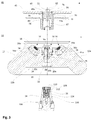
- the Fig. 1 shows a side sectional view of a rotor 10 according to the invention with attached cover 40 and activated locking of the lid 40th
- the rotor 10 has the basic shape of an upwardly tapering truncated cone.
- a rotor head 12 receptacles 14 for sample container 16 are arranged at regular intervals to each other in a conventional manner.
- the longitudinal extent of the receptacles 14 extends parallel to the lateral surface 12a of the rotor head 12.
- Fig. 1 four sample containers 16 introduced into the receptacles 14 are shown. Closure caps 16a of the sample containers 16 project from the respective receptacles 14 into a receiving space 18 of the rotor 10.
- a rotor seat 20 is concentrically introduced, which is assigned to the support 106 of the centrifuge 100.
- the rotor seat 20 has a truncated cone-shaped first section 20a, which tapers in a withdrawal direction E and adjoins in the axial direction a cylindrical second section 20b.
- the rotor seat 20 is delimited by a boundary surface 20c running perpendicular to the rotor axis R.
- this boundary surface 20c concentric with the support 106 of the centrifuge 100 and facing away from the boundary surface 20c away along the rotor axis R extending locking ball 22 is arranged, the function of the Figures 3 . 3a and 3b will be explained in more detail.
- rotor pin 34 is disposed in the receiving space 18, which has a conically tapered to its free end outer contour 34a.
- the rotor pin 34 is in Fig. 3 and especially in the cut-out drawing in Fig. 3a shown in more detail.
- a lid 40 On the rotor 10, a lid 40 is applied, which closes the receiving space 18 aerosol-tight to the outside.
- a handle 44 Concentric with the cover 40, a handle 44 is arranged, by means of which the cover 40 can be placed on the rotor 10 and removed from the rotor 10.
- the handle 44 is partially introduced into a blind hole cylindrical recess 42 of the lid 40 and with this firmly connected in a conventional manner.
- the recess 42 has a concentric with the rotor axis R formed opening 42a in the cylinder bottom of the recess through which engages the free end of the rotor pin 34 in the handle 44.
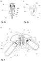
- the handle 44 in detail drawings in the Figures 2a, 2b and 2c shown.
- the handle 44 has a cylindrical bearing body 46, on the outer wall, a wall 48 is slidably disposed in the axial direction.
- two rocker arms 50 with respect to the rotor axis R are arranged opposite one another.
- the longitudinal extension of the rocker arm 50 is substantially aligned axially.
- the cross section of the rocker arm 50 has approximately centrally to the bearing body 46 facing toward thickening 52, which is rounded. Through these thickenings 52 in each case one of the better clarity, not shown strut 54, over which the rocker arm 50 is tilted.
- the strut 54 thus forms with the associated recess in the thickening 52 a tilting joint for the rocker arm relative to the bearing body 46 and this at least partially completely surrounding wall 48.
- actuator 56 extends to the Rocker arm 50.
- the cross section of the rocker arm 50 tapers towards the upper end respectively.
- the cross section of the rocker arm 50 likewise tapers in each case.
- the actuators 56 are each associated with a recess 46a in the bearing body 46 and a recess 48a in the wall 48, through which the actuators 56 partially projecting laterally out of the handle 44.
- each rocker arm 50 At the upper end of each rocker arm 50, a recess 60 is provided in each case, in which one end of a along the bearing body 46 of the handle 44 arranged spring 62, in particular leaf spring, engages.
- the springs 62 are clamped at their ends remote from the recesses 60 with the bearing body 46 and biased radially outward. Therefore, the upper ends of the rocker arms 50 are urged radially outwards by the spring 62 when, as in FIG Fig. 2a shown no manual application of force from the outside, and come into contact with the bearing body 46, and the actuating elements 56 protrude laterally out of the handle 44 maximum.
- Fig. 2b is the handle 44 with the rocker arms 50 in the identical position as in Fig. 2a , the locking position, shown.
- the wall 48 of the handle 44 is displaced axially relative to the bearing body 46 in the removal direction E.
- This relative change in position of the wall 48 relative to the bearing body 46 takes place when an operator grips the handle 44 and raises without loosening the lock between the cover 40 and the rotor 10 so that it does not act on the actuating elements 56 and thereby force the rocker arms 50 tilts and removes the locking elements 58 from the introduced into the outer contour 34a of the rotor pin 34 groove 34b.
- the wall 48 is acted upon by one of the better clarity, not shown spring acting against the withdrawal direction E force. As soon as the operator turns off the rotor 10 or inserts it into a centrifuge 100 and thus neutralizes the weight applied to the handle 44, the wall 48 returns to its original position and the blocking of the rocker arms 50 by the projection 48b is released. The projection 48b of the wall 48 thus forms a securing element which blocks or releases an actuation of the rocker arm 50 as needed, depending on the position in which it is located.
- FIG. 2c the wall 48 of the handle 44 is shown again in its initial position.
- the projection 48b is again below the rocker arm 50, whereby the in Fig. 2b shown Blocking of the rocker arm 50 is eliminated.
- the rocker arms 50 are tilted due to manual application of force to the actuators 56 about their tilting joints formed by strut 54 and associated recess 52 in the thickening, and the locking elements 58 are located outside the groove 34b. The lock between the rotor 10 and cover 40 is released, and the lid 40 can be removed from the rotor 10.
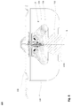
- Fig. 3 shows a side sectional view of the rotor 10 - with respect to the Fig. 1 and the Fig. 2a to 2c again rotated by 90 ° - in exploded view with removed cover 40 and a support 106 of a centrifuge 100, as shown schematically in Fig. 6 is shown.
- the closure ball 22 engages when placing the rotor 10 on the bearing 106 of the centrifuge 100 in an opening 110 of a concentrically arranged on the support 106 and bolted to the support 106 abutment insert 108 a.
- the opening 110 is sized so that the closure ball 22 can pass with minimal play.
- the opening 110 is adjoined by an inner contour 112 of the abutment insert 108 that widens conically against the removal direction E.
- a spring 24 is arranged, in which a for clarity in FIG. 3b separately shown blocking unit 26 is mounted and acted upon in withdrawal direction E acting spring force.
- the blocking unit 26 has four locking springs 30 connected via a connecting ring 28, at the end of which a blocking element 30a is attached.
- the locking elements 30a are adapted in shape substantially to the outer contour of the closure ball 22.
- the locking elements 30a and thus the entire locking unit 26 are first pressed by the penetrating through the opening 110 closure ball 22 down, in the region of the inner contour 112 in the abutment insert 108 which is larger than that Opening 110, so that the locking elements 30a can now be pushed apart.
- the blocking elements 30a then slide along the closure ball 22 until they finally engage around the closure ball 22 when the rotor 10 is fully seated on the support 106.
- the locking unit 30 moves through the spring force again in removal direction E, and the locking elements 30a come to the inner contour 112 of the abutment insert 108 in abutment.
- the circumference of the closing ball 22 with the blocking elements 30a increases so that passing through the opening 110 of the abutment insert 108 is no longer possible.
- the blocking elements 30a can pass through the plant on the inner contour 112 of the abutment insert 108 no longer move in the radial direction.
- the rotor 10 is thus securely fixed in the axial direction on the support 106 of the centrifuge 100.
- the closure ball 22 is penetrated by a bore 32.
- the bore 32 extends from the closure ball 22 through the rotor head 12 and the adjoining rotor pin 34 therethrough.
- the inner diameter of the bore 32 widens in removal direction E at a first shoulder 32a and again at a second shoulder 32b.
- a Entriegelungsdorn 36 Through the bore 32 engages a Entriegelungsdorn 36, which in turn has a first paragraph 32a of the bore 32 associated first paragraph 36a and the second paragraph 32b of the bore 32 associated second paragraph 36b.
- Fig. 3 Marked with III a region in which the introduced into the bore 32 Entriegelungsdorn 36 is shown enlarged in Fig. 3a shown.
- the mutually associated regions of the diameter of the Entriegelungsdorns 36 and the inner diameter of the bore 32 are adapted to each other so that the Entriegelungsdorn 36 in the bore 32 is axially displaceable.
- An axial movement of the Entriegelungsdorns 36 in the direction of the support 106 is limited and possible up to an end position at which the corresponding paragraphs 32a and 36a and the paragraphs 32b and 36b each come into contact with each other.
- the longitudinal extension of the unlocking mandrel 36 is dimensioned so that a free end 38 against the withdrawal direction E emerges from the closure ball 22 when moving the Entriegelungsdorns 36, engages in the locking unit 26 and the locking unit 26 against the force applied by the spring 24 increasingly displaces, also the locking elements 30a slide along the locking ball 22 in the region of the inner contour 112, which is wider than the opening 110 of the abutment insert 108, so that the locking elements 30a can bend outward.
- the blocking unit 26 Upon reaching the above-described end position of the unlocking mandrel 36, the blocking unit 26 is shifted by a distance s s far enough that the locking elements 30a completely release the locking ball 22, ie the locking elements 30a bend radially outwards when the locking ball 22 passes the locking elements 30a.
- the closure ball 22 can now again pass through the opening 110 of the abutment insert 108, and the rotor 10 can be removed from the abutment 106 of the centrifuge 100.
- an actuating pin 74 is provided in the handle 44, which forms an activation element 36, 74 together with the unlocking mandrel 36.
- a bearing insert 70 is introduced, which terminates flush on the side facing away from the rotor 10 side with the gripping pieces 45.
- An axial bore 72 passes through the bearing insert 70 and tapers stepwise at the end facing the rotor 10, so that an opening 72a is formed there whose diameter is less than the diameter of the bore 72.
- the actuating pin 74 is slidably mounted in the bore 72 and comprises a cylindrical first portion 76, whose diameter is adapted to the inner diameter of the bore 72, and a cylindrical second portion 78, whose diameter is adapted to the inner diameter of the opening 72 a.
- the second section 78 passes through the opening 72a and engages in a laterally limited by the bearing body 46 interior 47 of the handle 44 a.
- a formed between the first portion 76 and the second portion 78 paragraph 80 serves as a limitation for an axial displacement of the actuating pin 74 against the withdrawal direction E in an end position.
- the free end of the first portion 76 is formed as a push button 82 which protrudes completely out of the bearing insert 70 in the non-actuated state and has a height h D.
- the push button 82 Upon complete actuation of the push button 82, the push button 82 is flush with the exposed side of the bearing insert 70, and the actuating pin 74 is moved against the withdrawal direction E by a distance s B , which corresponds to the height h D. The actuating pin 74 thereby enters the previously described end position.
- the unlocking mandrel 36 and the actuating pin 74 are dimensioned in their length so that their ends facing each other in fully attached to the rotor 10 cover 40 in abutment come together.
- the unlocking mandrel 36 and the actuating pin 74 together form an activation element 36,74, by means of which the locking unit 26 axially displaced by the distance ss in a release position even with the cover 40 and the lock between the rotor 10 and shaft 104 can be deactivated as described above so that the rotor 10 can be removed from the support 106.
- the height h D of the push button 82 in the present embodiment has the same length as the distance s B and the distance s S.
- the push button 82 may also be formed higher, so that it protrudes from the bearing insert 70 in the activated state. However, the amount must not or only insignificantly h D s the length of track B and S s, otherwise the force required to release stroke of the locking unit 26 is no longer achieved and a release is no longer guaranteed.
- the activation element 36, 74 it is also possible to form the activation element 36, 74 in one piece and to store either in the handle 44 of the lid 40 or in the receiving space 18 of the rotor 10, in the rotor pin 34. If the activation element 36, 74 is mounted in the handle 44, the rotor pin 34 can be made more space-saving, or it can even be almost completely dispensed with the rotor pin 34.
- FIG. 4 As shown in perspective view, it can be seen how the locking mechanism 50, 34b for locking lid 40 and rotor and the locking device 22, 24, 26 for fixing the rotor 10 on the drive shaft 104 in the handle 44 are integrated. Conveniently, the two releases can be operated by the operator with just one hand, without significantly changing the position of the hand. As to unlock the locking device which fixes the rotor 10 on the shaft 104, a vertical pressure movement on the push button 82 is required, while the unlocking of the device which fixes the lid 40 on the rotor 10, on both sides horizontal pressure on the two actuators 56, the risk of incorrect operation is low.
- FIGS. 5a, 5b and 5c show analogous to the Figures 2a, 2b and 2c Detailed drawings of the introduced into the lid 40 handle 44 with an additional securing device, by the access state in the activated state is prevented to the locking element 50.
- the locking of the lid 40 is carried out as already described on the rocker arm 50.
- a latching element 58 is arranged, which engages in the locked state of the cover 40 in the provided in the rotor pin 34 groove 34a.
- the cover 40 is fixed axially on the rotor pin 34 and thus locked to the rotor 10.
- the rocker arms 50 are tiltably mounted on the struts 54. By a force applied to the arranged at the upper end of the rocker arm 50 actuators 56 in the direction of the rotor axis R, the rocker arm 50 are tilted to unlock so that the locking elements 58 slide out of the groove 34a and the determination of the lid 40 is released on the rotor pin 34.
- the activation of the securing of the locking takes place by lifting the handle 44.
- the wall 48 and arranged on the wall 48 projections 48b are axially displaced in the withdrawal direction E.
- a projection 48b comes into abutment with its associated rocker arm 50, so that the movement of the rocker arm 50 is blocked.
- the locking element 58 is fixed in the groove 34b, and the locking of the cover 40 and the rotor 10 is secured.
- cover 48c Arranged at the free end of the wall 48 of the rotor axis R facing away cover 48c have, together with the wall 48 of the handle 44 has an upwardly open U-shaped cross-section.
- the cover 48c are dimensioned so that their upwardly facing free ends reach below the actuators 56 when the handle 44 is in the unactuated starting position, as in Fig. 5a shown.
- the actuators 56 are freely accessible.
- FIG. 5b the rocker arms 50 are in the identical position as in FIG Fig. 5a , the locking position, shown.
- the wall 48 of the handle 44 together with the projections 48b and cover elements 48c is displaced axially relative to the bearing body 46 in the removal direction E.
- the actuators 56 each intervene in the area between the cover 48c and wall 48, so that their free ends are no longer accessible and manual application of force by an operator and thus releasing the locking of the lid 40 and Rotor 10 is prevented.
- the lock is secured both by blocking the movement of the rocker arm 50 and by a cover of the actuators Ab 56 against incorrect operation.
- Fig. 6 shows a side sectional view of a centrifuge 100 according to the invention, is omitted for clarity in the representation of a housing and a bottom.
- FIGS. 1 to 4 described rotor 10 as already in connection with Fig. 3 is connected via the support 106 with the drive shaft 104 and rotated about the rotor axis R.
- the drive shaft 104 is driven by the underlying motor 102.
- the rotor 10 is surrounded by a safety boiler 116.
- the engine 102 engages the safety boiler 116 through an opening 116a.
- a centrifuge lid 118 is provided, which is connected to the housing, not shown, in a conventional manner and the centrifuge 100 closes at its top.
Landscapes
- Centrifugal Separators (AREA)
Abstract
Die Erfindung betrifft einen Rotor (10) einer Zentrifuge (100), mit einem Aufnahmeraum (18) für zu zentrifugierende Proben, einem konzentrisch angeordneten Sitz (20), der einem Auflager (106) einer Antriebswelle (104) der Zentrifuge (100) zugeordnet ist, einem Deckel (40), der den Aufnahmeraum (18) nach oben begrenzt, konzentrisch zum Rotor angeordnet ist und auf seiner dem Aufnahmeraum (18) entfernt gelegenen Seite eine Handhabe (44) zum Tragen von Rotor und Deckel aufweist, und einem Verriegelungsmechanismus (50, 34b) von Deckel (40) und Rotor, wobei der Verriegelungsmechanismus ein zwischen einer Verriegelungsposition und einer Entriegelungsposition bewegbares Verriegelungselement (50) umfasst. Die Erfindung zeichnet sich dadurch aus, dassdie Handhabe (44) teilweise bewegbar ausgeführt ist und in Wirkverbindung mit einem Sicherungselement (48b, 48c) steht, wobei das Sicherungselement (48b, 48c) zwischen einer ersten Position, in der das Betätigen des Verriegelungselements (50) verhindert wird,und einer das Verriegelungselement (50) freigebenden zweiten Position mittels der Handhabe (44) bewegbar ist.The invention relates to a rotor (10) of a centrifuge (100), having a receiving space (18) for samples to be centrifuged, a concentrically arranged seat (20) associated with a support (106) of a drive shaft (104) of the centrifuge (100) is, a cover (40) which delimits the receiving space (18) upwardly, is arranged concentrically to the rotor and on its the receiving space (18) remote side having a handle (44) for supporting the rotor and lid, and a locking mechanism (50, 34b) of the cover (40) and the rotor, wherein the locking mechanism comprises a locking member (50) movable between a locking position and an unlocking position. The invention is characterized in that the handle (44) is made partially movable and is in operative connection with a securing element (48b, 48c), the securing element (48b, 48c) being movable between a first position in which the actuation of the locking element (50 ) is prevented, and a second position releasing the locking element (50) by means of the handle (44) is movable.
Description
Die Erfindung betrifft einen Rotor einer Zentrifuge gemäß der im Oberbegriff des Patentanspruches 1 angegebenen Art und eine Zentrifuge mit diesem Rotor.The invention relates to a rotor of a centrifuge according to the type specified in the preamble of claim 1 and a centrifuge with this rotor.
Aus dem Stand der Technik ist eine Vielzahl von Rotoren für Zentrifugen bekannt, deren Aufnahmeraum mit einem Deckel verschließbar ist. Dies dient dem Schutz der Zentrifuge und der Umgebung vor Kontaminierung im Falle eines Gefäßbruchs.From the prior art, a plurality of rotors for centrifuges is known, the receiving space is closed with a lid. This serves to protect the centrifuge and the environment from contamination in the event of vessel rupture.
Es erhöht dabei die Betriebssicherheit, wenn ein Mechanismus vorgesehen ist, der den Verschluss des Deckels verriegelt. Beispielsweise kann der Verschluss ein Rastelement aufweisen, das mit einem an der Deckeloberseite angeordneten Aktivierungselement, etwa einem Druckknopf, versehen ist. Das Rastelement kann ferner in eine Verriegelungsrichtung federbelastet sein, so dass es beim Verschließen automatisch einrastet und durch Drücken des Druckknopfs deaktiviert wird. Die Ver- und Entriegelung ist für den Benutzer sehr bequem.It increases the reliability when a mechanism is provided which locks the closure of the lid. For example, the closure may have a latching element which is provided with an activation element arranged on the top of the cover, for example a pushbutton. The locking element may also be spring-loaded in a locking direction, so that it locks automatically when closing and is deactivated by pressing the push button. The locking and unlocking is very convenient for the user.
Allerdings hat es sich in der Praxis gezeigt, dass gerade solche Lösungen, die ein besonders einfaches Lösen der Verrieglung des Deckels ermöglichen, die Gefahr bergen, dass das Lösen der Verriegelung unabsichtlich erfolgt. Denn häufig weist der Deckel eine Handhabe auf, über die der mit dem Deckel verschlossene Rotor getragen werden kann. Wenn während des Tragens die Verriegelung unabsichtlich deaktiviert wird, löst sich der Rotor vom Deckel und fällt zu Boden.However, it has been found in practice that precisely those solutions which enable a particularly simple release of the locking of the cover, the risk that the release of the lock is done unintentionally. Because often, the lid has a handle over which the closed with the lid rotor can be worn. If the lock is inadvertently deactivated during wear, the rotor will detach from the cover and fall to the ground.
Aus der
Aufgabe der Erfindung ist es, unter Vermeidung der genannten Nachteile einen Rotor zu schaffen, der einen Deckel mit einer Handhabe zum Tragen des Rotors mit Deckel aufweist, wobei der Rotor und der Deckel über einen Schnellverschluss miteinander verriegelbar sind und die Verriegelung gegen ein Lösen solange gesichert ist, während der Rotor an der Handhabe getragen wird.The object of the invention is to provide a rotor while avoiding the disadvantages mentioned, which has a lid with a handle for supporting the rotor with lid, wherein the rotor and the lid are locked together via a quick release and secured the lock against loosening is while the rotor is carried on the handle.
Diese Aufgabe wird durch die kennzeichnenden Merkmale des Patentanspruches 1 in Verbindung mit seinen Oberbegriffsmerkmalen gelöst.This object is achieved by the characterizing features of claim 1 in conjunction with its generic features.
Die Unteransprüche bilden vorteilhafte Weiterbildungen der Erfindung.The dependent claims form advantageous developments of the invention.
Der Erfindung liegt die Erkenntnis zugrunde, dass durch eine Sicherung der Verriegelung des Rotors mit dem Deckel in der Handhabe die genannten Nachteile auf einfache Weise vermieden werden können.The invention is based on the finding that the disadvantages mentioned can be avoided in a simple manner by securing the locking of the rotor with the cover in the handle.
Nach der Erfindung weist ein Rotor einer Zentrifuge einen Aufnahmeraum für zu zentrifugierende Proben, einen konzentrisch angeordneten Sitz, der einem Auflager einer Antriebswelle der Zentrifuge zugeordnet ist, einen Deckel, der den Aufnahmeraum nach oben begrenzt und konzentrisch zum Rotor angeordnet ist und auf dessen dem Aufnahmeraum entfernt gelegenen Seite eine Handhabe zum Tragen von Rotor und Deckel vorgesehen ist, auf. Ferner weist der Rotor einen Verriegelungsmechanismus von Deckel und Rotor auf, wobei der Verriegelungsmechanismus ein zwischen einer Verriegelungsposition und einer Entriegelungsposition bewegbares Verriegelungselement umfasst und als Schnellverschluss ausgebildet ist. Für den Schnellverschluss wird kein zusätzliches Werkzeug benötigt. Gemäß der erfindungsgemäßen Ausgestaltung ist die Handhabe teilweise bewegbar ausführt und steht die Handhabe in Wirkverbindung mit einem Sicherungselement, wobei das Sicherungselement zwischen einer ersten Position in der das Betätigen des Verriegelungselements verhindert wird, und einer das Verriegelungselement freigebenden zweiten Position mittels der Handhabe bewegbar ist. So kann eine Position der Handhabe festgelegt werden, vorzugsweise zum Tragen des Rotors, in der das Sicherungselement aktiviert ist, so dass das Betätigen des Verriegelungselements verhindert wird und der Verriegelungsmechanismus entweder in der Verriegelungsposition oder in der Entriegelungsposition bleibt, bis die Position der Handhabe wieder verändert wird. Dies hilft, Bedienerfehler zu vermeiden und verbessert die Sicherheit des Rotors.According to the invention, a rotor of a centrifuge has a receiving space for samples to be centrifuged, a concentrically arranged seat which is assigned to a support of a drive shaft of the centrifuge, a cover which delimits the receiving space upwards and concentric with the rotor and on which the receiving space located on the remote side a handle for carrying rotor and lid is provided on. Furthermore, the rotor has a locking mechanism of the cover and rotor, wherein the locking mechanism comprises a movable between a locking position and an unlocking locking element and is designed as a quick release. The quick release does not require any additional tools. According to the embodiment of the invention, the handle is partially movable executes and the handle is in operative connection with a securing element, wherein the securing element between a first position in which the actuation of the locking element is prevented, and a locking element releasing the second position by means of the handle is movable. Thus, a position of the handle can be determined, preferably for supporting the rotor in which the securing element is activated, so that the actuation of the locking element is prevented and the locking mechanism either in the locking position or in the unlocking position remains until the position of the handle changes again becomes. This helps to avoid operator error and improves the safety of the rotor.
Bei einer vorteilhaften Weiterbildung der Erfindung ist das Sicherungselement als Abdeckelement ausgebildet, das in aktiviertem Zustand einen Zugriff auf das Verriegelungselement verhindert, und/oder das Sicherungselement ist als Blockierelement ausgebildet, das in aktiviertem Zustand das Verriegelungselement in der Verriegelungsposition festlegt. Wenn die Aktivierung des Abdeckelements und/oder des Blockierelements entsprechend gewählt ist, werden dadurch ein unbeabsichtigtes Lösen des Verriegelungsmechanismus während des Tragens und ein Herunterfallen des Rotors vermieden, was die Sicherheit des Rotors nochmals erheblich verbessert.In an advantageous embodiment of the invention, the securing element is designed as a cover, which prevents access to the locking element in the activated state, and / or the securing element is designed as a blocking element, which defines the locking element in the locked position in the activated state. If the activation of the cover member and / or the blocking element is selected accordingly, thereby an accidental release of the locking mechanism during wear and a fall of the rotor is avoided, which again significantly improves the safety of the rotor.
Gemäß einem Aspekt der Erfindung weist der Deckel ein Lager für das Verriegelungselement auf. Dadurch wird der Verriegelungsmechanismus stabilisiert, was eine geringere Fehleranfälligkeit zur Folge hat.According to one aspect of the invention, the lid has a bearing for the locking element. As a result, the locking mechanism is stabilized, resulting in a lower susceptibility to failure.
Sehr günstig ist es, wenn das Lager konzentrisch zum Deckel angeordneten und mit dem Deckel fest verbundenen Lagerkörper, insbesondere in Form eines Zylinders, eingebracht ist. Der Verriegelungsmechanismus gewinnt dadurch weiter an Stabilität.It is very advantageous if the bearing is arranged concentrically with the cover and fixedly connected to the cover bearing body, in particular in the form of a cylinder is introduced. The locking mechanism thereby gains further stability.
Es ist zweckmäßig, dass die Handhabe konzentrisch zum Lagerkörper angeordnet und relativ zum Lagerkörper bewegbar gelagert ist. So kann durch der Handhabe eine zusätzliche Funktion zugewiesen werden, die sie erfüllt, wenn sie relativ zum Lagerkörper bewegt wird. Beispielsweise kann die Handhabe mit einem weiteren Element so verbunden sein, das sie das Element bei der Bewegung in eine Richtung aktiviert und bei einer Bewegung in die entgegengesetzte Richtung deaktiviert.It is expedient that the handle is arranged concentrically to the bearing body and is mounted movable relative to the bearing body. Thus, the handle can be assigned an additional function, which it fulfills when it is moved relative to the bearing body. For example, the handle can be connected to another element so that it activates the element when moving in one direction and deactivated when moving in the opposite direction.
Vorzugsweise ist die Handhabe mit dem aktivierbaren Blockierelement einstückig ausgebildet und mit dem Blockierelement relativ zum Lagerkörper bewegbar zwischen einer das Verriegelungselement in der Verriegelungsposition blockierenden ersten Position und einer das Verriegelungselement freigebenden zweiten Position. Dabei ist das Verriegelungselement nur in der zweiten Position aus der Verriegelungsposition in die Entriegelungsposition bewegbar.Preferably, the handle with the activatable blocking element is integrally formed and movable with the blocking element relative to the bearing body between a locking element in the locking position blocking the first position and the locking element releasing second position. In this case, the locking element is movable only in the second position from the locking position to the unlocking position.
Gemäß einer Ausführungsform der Erfindung hat es sich als vorteilhaft erwiesen, dass eine Verschiebung der Handhabe auf dem Lagerkörper entlang der Rotorachse von der ersten Position in die zweite Position und vice versa erfolgt. Da zum Einsetzen des Rotors in die Zentrifuge sowie zum Entnehmen des Rotors aus der Zentrifuge die Handhabe ebenfalls entlang der Drehachse bewegt wird, erfolgen die Verschiebung der Handhabe zum Aktivieren / Deaktivieren des Blockierelements und die Verschiebung der Handhabe zum Entnehmen / Einsetzen koaxial zueinander. Dies erspart dem Bediener eine zusätzliche Bewegung und erleichtert daher die Bedienung des Rotors.According to one embodiment of the invention, it has proven to be advantageous that a displacement of the handle on the bearing body along the rotor axis from the first position to the second position and vice versa takes place. As for the insertion of the rotor into the centrifuge and for removing the rotor from the centrifuge, the handle is also moved along the axis of rotation, carried out the displacement of the handle for activating / deactivating the blocking element and the Displacement of the handle for removal / insertion coaxial with each other. This saves the operator additional movement and therefore facilitates the operation of the rotor.
Es ist zweckmäßig, dass eine Bewegung der Handhabe mit Blockierelement vom Deckel weg einer Bewegung in die erste Position und eine Bewegung der Handhabe mit Blockierelement zum Deckel hin einer Bewegung in die zweite Position entspricht. So wird beim Anheben der Handhabe, sofern das Verriegelungselement nicht bereits zuvor in die Entriegelungsposition bewegt wurde, das Blockierelement aktiviert, und der Rotor wird mitsamt dem Deckel angehoben. Auf Grund der auf den Rotor einwirkenden Schwerkraft verbleibt die Handhabe mit dem Blockierelement während des Tragens in der vom Deckel entfernt gelegenen ersten Position, in der das Verriegelungselement blockiert ist, und kann nicht durch Unachtsamkeit gelöst werden. Diese Anordnung bewirkt somit eine zuverlässige Blockierung der Verriegelung und erhöht die Sicherheit des Rotors während eines Transports erheblich.It is expedient that a movement of the handle with blocking element away from the cover corresponds to a movement into the first position and a movement of the handle with blocking element towards the cover means a movement into the second position. Thus, when lifting the handle, unless the locking element has been previously moved to the unlocking position, the blocking element is activated, and the rotor is lifted together with the lid. Due to the gravitational force acting on the rotor, the handle remains with the blocking member during wearing in the first position away from the lid, in which the locking member is blocked, and can not be loosened by carelessness. This arrangement thus causes a reliable blocking of the lock and increases the safety of the rotor during transport considerably.
Bei einer vorteilhaften Weiterbildung der Erfindung ist die Handhabe in Richtung des Deckels federbelastet. Dadurch bewegt sich die Handhabe mit dem Blockierelement selbsttätig in die zweite Position, sobald der Rotor in eine Zentrifuge eingesetzt oder auf eine Unterlage gestellt wird, der Bediener die Handhabe freigibt und somit keine in Richtung vom Deckel weg wirkende Kraft mehr auf die Handhabe ausgeübt wird. Das Verriegelungselement ist nunmehr in eine Entriegelungsposition bewegbar. Diese selbsttätige Bewegung der Handhabe erspart dem Bediener eine weitere Bewegung und vereinfacht wiederum die Bedienung des Rotors.In an advantageous embodiment of the invention, the handle is spring-loaded in the direction of the lid. As a result, the handle moves automatically with the blocking element in the second position, as soon as the rotor is inserted into a centrifuge or placed on a base, the operator releases the handle and thus no force acting in the direction away from the lid force is exerted more on the handle. The locking element is now movable in an unlocked position. This automatic movement of the handle saves the operator another movement and in turn simplifies the operation of the rotor.
Gemäß einem Aspekt der Erfindung durchgreift der Verriegelungsmechanismus bereichsweise die Handhabe, insbesondere seitlich. Dadurch ist der Verriegelungsmechanismus gut zugänglich, was den Bedienkomfort des Rotors erhöht. Zugleich sind Aktivierung/Deaktivierung des Verriegelungsmechanismus und der Sperreinrichtung haptisch besser voneinander unterscheidbar. Besonders gut unterscheidbar sind sie, wenn die Aktivierungsrichtungen des Verriegelungsmechanismus und der Sperreinrichtung etwa im senkrechten Winkel zueinander stehen. Dies verbessert die Sicherheit des Rotors weiter.According to one aspect of the invention, the locking mechanism passes through the handle in regions, in particular laterally. As a result, the locking mechanism is easily accessible, which increases the ease of use of the rotor. At the same time activation / deactivation of the locking mechanism and the locking device are haptically better distinguishable from each other. They are particularly well distinguishable when the activation directions of the locking mechanism and the locking device are approximately at a right angle to each other. This further improves the safety of the rotor.
Gemäß einer Ausführungsform der Erfindung ist das Verriegelungselement ein Kipphebel. Kipphebel sind für einfach lösbare Verriegelungen von zwei Bauteilen miteinander gut geeignet und leicht zu verbauen. Dies reduziert sowohl den Konstruktionsaufwand als auch die Kosten. Zudem können über den Kipphebel Räume in vertikaler Richtung überbrückt werden, so dass sich weitere konstruktive Optimierungsmöglichkeiten ergeben.According to one embodiment of the invention, the locking element is a rocker arm. Rocker arms are well suited for easily releasable locking of two components together and easy to install. This reduces both the design effort and the cost. In addition, spaces can be bridged in the vertical direction via the rocker arm, resulting in further design optimization possibilities.
Günstig ist es, wenn der Kipphebel in Richtung der Verriegelungsposition federbelastet ist. Dies gewährleistet eine sichere selbsttätige Verriegelung des Deckels beim Aufsetzen auf den Rotor und erleichtert somit die Bedienung des Rotors.It is advantageous if the rocker arm is spring-loaded in the direction of the locking position. This ensures a secure automatic locking of the lid when placed on the rotor and thus facilitates the operation of the rotor.
Bei einer vorteilhaften Weiterbildung der Erfindung ist das untere Ende des Kipphebels als Rastelement ausgebildet, das in der Verriegelungsposition in eine in den Rotor eingebrachte Nut eingreift, die zum Aufnahmeraum offen ist. Über das obere Ende des Kipphebels ist der Kipphebel durch Drücken aus der Verriegelungsposition lösbar. Die Maße des Kipphebels bzw. der Kipphebel, ihre Lagerung und die Anordnung der Kippachse können leicht so gewählt werden, dass eine Verriegelung herstellbar ist, die zum einen ausreichend stabil ist, um den Rotor an der Handhabe des verriegelten Deckels sicher zu transportieren, und die zum anderen nach dem Transport schnell vom Bediener gelöst werden kann. Dadurch wird eine sichere und zugleich flexible Verriegelung von Deckel und Rotor erreicht.In an advantageous embodiment of the invention, the lower end of the rocker arm is designed as a latching element which engages in the locking position in an introduced into the rotor groove, which is open to the receiving space. Over the upper end of the rocker arm of the rocker arm is released by pressing from the locking position. The dimensions of the rocker arm or the rocker arm, their storage and the arrangement of the tilting axis can be easily chosen so that a lock can be produced, which is sufficiently stable to securely transport the rotor to the handle of the locked lid, and the On the other hand, it can be quickly released by the operator after transport. As a result, a secure and flexible locking of the lid and rotor is achieved.
Gemäß einem weiteren Aspekt der Erfindung ist eine Sperrvorrichtung zur Festlegung des Rotors relativ zur Antriebswelle der Zentrifuge vorgesehen, wobei im Deckel ein Aktivierungselement zur Aktivierung der Sperrvorrichtung gelagert ist, das bei aufgebrachtem Deckel zugänglich ist. Dadurch ist die Sperrvorrichtung aktivierbar und deaktivierbar, ohne dabei den Deckel vom Rotor abzunehmen. Dies ist von besonderem Vorteil, wenn beispielsweise nach einem Gefäßbruch im Rotor eine Kontamination der Umgebung vermieden werden muss. Die Verbindung zwischen Rotor und Antriebswelle kann gelöst und der Rotor mit aufgebrachtem Deckel aus der Zentrifuge entnommen werden. So wird der Betrieb des Rotors sicherer.According to a further aspect of the invention, a locking device is provided for fixing the rotor relative to the drive shaft of the centrifuge, wherein an activation element for activating the locking device is mounted in the lid, which is accessible when the lid is applied. As a result, the locking device can be activated and deactivated without removing the cover from the rotor. This is of particular advantage if, for example, after a vascular fracture in the rotor contamination of the environment must be avoided. The connection between the rotor and the drive shaft can be loosened and the rotor with the cover removed can be removed from the centrifuge. This makes the operation of the rotor safer.
Vorzugsweise weist die Sperrvorrichtung eine Sperreinheit auf, die mittels des Aktivierungselements zwischen einer Sperrstellung und einer Freigabestellung bewegbar ist. Das Aktivierungselement ist leicht in einen einfachen Druck- oder Schiebemechanismus integrierbar. So kann eine sichere Festlegung bzw. Freigabe des Rotors kostengünstig und mit wenig Konstruktionsaufwand erreicht werden.Preferably, the locking device has a locking unit, which is movable by means of the activation element between a blocking position and a release position. The activation element is easily integrated into a simple push or push mechanism. Thus, a secure fixing or release of the rotor can be achieved inexpensively and with little design effort.
Bei einer vorteilhaften Weiterbildung der Erfindung ist die Sperreinheit in Richtung der Sperrstellung federbelastet. Dadurch kann die Aktivierung der Sperrvorrichtung in die Sperrstellung durch Einsetzen des Rotors ohne eine zusätzliche manuelle Betätigung geschehen.In an advantageous embodiment of the invention, the locking unit is spring-loaded in the direction of the blocking position. Thereby, the activation of the locking device can be done in the locked position by inserting the rotor without an additional manual operation.
Günstig ist es, wenn das Aktivierungselement in einer Richtung parallel zu einer Rotorachse betätigbar ist. Dadurch erfolgen Festlegung und Freigabe des Rotors parallel zu der Richtung, in der Einsetzen und Entnahme des Rotors in die bzw. aus der Zentrifuge. Das Aktivierungselement ist dadurch noch leichter in den Rotor integrierbar, und das Risiko eines Verklemmens der Sperrvorrichtung wird minimiert.It is favorable if the activation element can be actuated in a direction parallel to a rotor axis. As a result, fixing and releasing of the rotor take place parallel to the direction in which insertion and removal of the rotor in and out of the centrifuge. The activation element is thereby even easier to integrate into the rotor, and the risk of jamming of the locking device is minimized.
Um dem Bediener die Benutzung des Rotors noch weiter zu erleichtern, hat es sich als vorteilhaft erwiesen, wenn das Aktivierungselement zumindest bereichsweise in der Handhabe gelagert ist. So wird eine einhändige Betätigung des Aktivierungselements erleichtert, da die Handhabe zugleich als Führung für das Aktivierungselement und als Abstützelement für die Hand dient.In order to make the use of the rotor even easier for the operator, it has proved to be advantageous if the activation element is mounted at least in regions in the handle. Thus, a one-handed operation of the activation element is facilitated because the handle also serves as a guide for the activation element and as a supporting element for the hand.
Vorzugsweise ist dabei am von der Sperreinheit entfernten Ende des Aktivierungselements ein Druckknopf vorgesehen, der sich in der Sperrstellung des Aktivierungselements zumindest bereichsweise außerhalb der Handhabe befindet. Die Längserstreckung des außerhalb der Handhabe liegenden Bereichs entspricht zumindest einer Hubhöhe h, die zum Lösen der Sperrvorrichtung erforderlich ist. So erfolgt die Deaktivierung der Sperrvorrichtung durch einfaches Drücken und ist für den Benutzer besonders angenehm.Preferably, a push button is provided at the remote from the blocking unit end of the activation element, which is at least partially outside the handle in the blocking position of the activation element. The longitudinal extension of the area lying outside the handle corresponds to at least one lifting height h, which is required for releasing the locking device. Thus, the deactivation of the locking device by simply pressing and is particularly pleasant for the user.
Nach der Erfindung ist ferner eine Zentrifuge vorgesehen, die einen Antrieb und eine Antriebswelle aufweist, an deren freiem Ende ein Auflager für einen Rotor nach einem der vorangehenden Ansprüche mit seinem Sitz anliegt.According to the invention, a centrifuge is further provided which has a drive and a drive shaft at the free end of a support for a rotor according to one of the preceding claims rests with its seat.
Gemäß einem Aspekt der Erfindung weist die Sperrvorrichtung einen Sperrkörper auf, der mit der Sperreinheit zusammenwirkt und dadurch den Rotor relativ zur Antriebswelle festlegt. Dadurch wird die Sperrwirkung der Sperrvorrichtung erhöht und der Betrieb der Zentrifuge deutlich sicherer gestaltet.According to one aspect of the invention, the locking device on a locking body which cooperates with the locking unit and thereby determines the rotor relative to the drive shaft. As a result, the blocking effect of the locking device is increased and designed the operation of the centrifuge much safer.
Bei einer vorteilhaften Weiterbildung der Erfindung ist der Sperrkörper am Sitz des Rotors angeordnet, greift durch eine im Auflager vorgesehene Ausnehmung zumindest bereichsweise in das Auflager ein und wird in der Sperrstellung so von der Sperreinheit umgriffen, dass der äußere Umfang der den Sperrkörper umgreifenden Sperreinheit größer ist als der innere Umfang der Ausnehmung. Auf diese Weise wird mit geringem Aufwand eine stabile Festlegung des Rotors relativ zur Antriebswelle erreicht, und die Sicherheit der Zentrifuge wird erheblich verbessert.In an advantageous embodiment of the invention, the locking body is arranged on the seat of the rotor, engages at least partially in the support by a recess provided in the support and is encompassed in the locking position of the locking unit, that the outer periphery of the lock body encompassing locking unit is greater as the inner circumference of the recess. In this way, a stable fixing of the rotor relative to the drive shaft is achieved with little effort, and the safety of the centrifuge is significantly improved.
Weitere Vorteile, Merkmale und Anwendungsmöglichkeiten der vorliegenden Erfindung ergeben sich aus der nachfolgenden Beschreibung in Verbindung mit den in den Zeichnungen dargestellten Ausführungsbeispielen.Further advantages, features and possible applications of the present invention will become apparent from the following description in conjunction with the embodiments illustrated in the drawings.
In der Beschreibung, in den Ansprüchen und in der Zeichnung werden die in der unten aufgeführten Liste der Bezugszeichen verwendeten Begriffe und zugeordneten Bezugszeichen verwendet. In der Zeichnung bedeutet:
- Fig. 1
- eine seitliche Schnittansicht eines erfindungsgemäßen Rotors mit aufgesetztem Deckel und aktivierter Verriegelung des Deckels (Schnitt durch die Rotorachse);
- Fig. 2a
- eine seitliche Schnittansicht des in
Fig. 1 gezeigten Deckels mit aktivierter Verriegelung und deaktivierter Blockierung; - Fig. 2b
- eine seitliche Schnittansicht des Deckels mit aktivierter Verriegelung und aktivierter Blockierung;
- Fig. 2c
- eine seitliche Schnittansicht des Deckels mit deaktivierter Verriegelung und deaktivierter Blockierung;
- Fig. 3
- eine seitliche Schnittansicht des in
Fig. 1 gezeigten Rotors mit abgenommenem Deckel sowie des Rotoraufnahmebereichs der Antriebswelle einer Zentrifuge; - Fig. 3a
- einen mit IIIa gekennzeichneten Ausschnitt aus
Fig. 3 ; - Fig. 3b
- eine Perspektivansicht eines Sperrelements;
- Fig. 4
- eine perspektivische Schnittansicht analog von
Fig. 1 des Rotors; - Fig. 5a
- eine seitliche Schnittansicht des Deckels mit aktivierter Verriegelung und deaktivierter Abdeckung einer alternativen Ausführungsform;
- Fig. 5b
- eine seitliche Schnittansicht des Deckels mit aktivierter Verriegelung und aktivierter Abdeckung der alternativen Ausführungsform;
- Fig. 5c
- eine seitliche Schnittansicht des Deckels mit deaktivierter Verriegelung und deaktivierter Abdeckung der alternativen Ausführungsform; und
- Fig. 6
- eine seitliche Schnittansicht einer erfindungsgemäßen Zentrifuge.
- Fig. 1
- a sectional side view of a rotor according to the invention with an attached lid and activated locking of the lid (section through the rotor axis);
- Fig. 2a
- a side sectional view of the in
Fig. 1 shown lids with activated lock and disabled blocking; - Fig. 2b
- a side sectional view of the lid with activated locking and activated blocking;
- Fig. 2c
- a side sectional view of the lid with disabled locking and blocking disabled;
- Fig. 3
- a side sectional view of the in
Fig. 1 shown rotor with the cover removed and the rotor receiving portion of the drive shaft of a centrifuge; - Fig. 3a
- a section marked IIIa
Fig. 3 ; - Fig. 3b
- a perspective view of a locking element;
- Fig. 4
- a perspective sectional view analogous
Fig. 1 the rotor; - Fig. 5a
- a side sectional view of the lid with activated lock and deactivated cover of an alternative embodiment;
- Fig. 5b
- a side sectional view of the lid with activated latch and activated cover of the alternative embodiment;
- Fig. 5c
- a side sectional view of the lid with deactivated lock and deactivated cover of the alternative embodiment; and
- Fig. 6
- a side sectional view of a centrifuge according to the invention.
Die
Der Rotor 10 hat die Grundform eines sich nach oben verjüngenden Kegelstumpfs. In einen Rotorkopf 12 sind in herkömmlicher Weise Aufnahmen 14 für Probenbehälter 16 in gleichmäßigen Abständen zueinander angeordnet. Die Längserstreckung der Aufnahmen 14 verläuft parallel zur Mantelfläche 12a des Rotorkopfs 12. In
In einer Unterseite 12b des Rotorkopfs 12 ist ein Rotorsitz 20 konzentrisch eingebracht, der dem Auflager 106 der Zentrifuge 100 zugeordnet ist. Der Rotorsitz 20 weist einen sich in eine Entnahmerichtung E verjüngenden kegelstumpfförmigen ersten Abschnitt 20a auf, an den sich in axialer Richtung ein zylindrischer zweiter Abschnitt 20b anschließt. Nach oben wird der Rotorsitz 20 von einer senkrecht zur Rotorachse R verlaufenden Begrenzungsfläche 20c begrenzt. An dieser Begrenzungsfläche 20c ist konzentrisch eine dem Auflager 106 der Zentrifuge 100 zugewandte und von der Begrenzungsfläche 20c weg entlang der Rotorachse R sich erstreckende Verschlusskugel 22 angeordnet, deren Funktion anhand der
Oberhalb der Verschlusskugel 22 ist in den Aufnahmeraum 18 konzentrisch zur Rotorachse R sich erstreckender Rotorzapfen 34 angeordnet, der eine sich zu seinem freien Ende hin konisch verjüngende Außenkontur 34a aufweist. Der Rotorzapfen 34 ist in
Auf den Rotor 10 ist ein Deckel 40aufgebracht, der den Aufnahmeraum 18 aerosoldicht nach außen abschließt. Konzentrisch zum Deckel 40 ist eine Handhabe 44 angeordnet, mittels der der Deckel 40 auf den Rotor 10 aufgesetzt und vom Rotor 10 abgenommen werden kann. Die Handhabe 44 ist bereichsweise in eine sacklochförmige zylindrische Vertiefung 42 des Deckels 40 eingebracht und mit diesem in herkömmlicher Weise fest verbunden. Die Vertiefung 42 weist eine konzentrisch zur Rotorachse R ausgebildete Öffnung 42a im Zylinderboden der Vertiefung auf, durch die das freie Ende des Rotorzapfens 34 in die Handhabe 44 eingreift.On the
Der besseren Übersichtlichkeit halber ist die Handhabe 44 in Detailzeichnungen in den
Den Betätigungselementen 56 sind jeweils eine Ausnehmung 46a in dem Lagerkörper 46 und eine Ausnehmung 48a in der Wandung 48 zugeordnet, durch die die Betätigungselemente 56 hindurch bereichsweise seitlich aus der Handhabe 44 herausstehen.The
Am oberen Ende jedes Kipphebels 50 ist jeweils eine Ausnehmung 60 vorgesehen, in die ein Ende einer entlang des Lagerkörpers 46 der Handhabe 44 angeordneten Feder 62, insbesondere Blattfeder, eingreift. Die Federn 62 sind an ihren von den Ausnehmungen 60 entfernten Enden mit dem Lagerkörper 46 verklemmt und radial nach außen vorgespannt. Daher werden die oberen Enden der Kipphebel 50 durch die Feder 62 radial nach außen gedrückt, wenn wie in
In
Mit der relativen Lageveränderung der Wandung 48 wird ein am in Richtung des Aufnahmeraums 18 weisenden Ende der Wandung 48 in Richtung der Rotorachse R sich erstreckender, den Lagerkörper 46 in einer nicht dargestellten Ausnehmung durchgreifender Vorsprung 48b mit verfahren. Durch das Anheben der Wandung 48 in Entnahmerichtung E gelangt der Vorsprung 48b jeweils im Bereich zwischen der Verdickung 52 und dem Rastelement 58 in Anlage an den Kipphebel 50. Dadurch wird der Kipphebel 50 blockiert, der Kipphebel 50 kann nicht um die Strebe kippen und das Rastelement 58 ist somit in der Nut 34b festgelegt. Die Verriegelung zwischen Rotor 10 und Deckel 40 kann in dieser Blockierposition nicht gelöst werden.With the relative change in position of the
Die Wandung 48 ist durch eine der besseren Übersichtlichkeit halber nicht dargestellte Feder mit einer entgegen der Entnahmerichtung E wirkenden Kraft beaufschlagt. Sobald der Bediener den Rotor 10 abstellt oder in eine Zentrifuge 100 einsetzt und somit die auf die Handhabe 44 aufgebrachte Gewichtskraft neutralisiert ist, gelangt die Wandung 48 wieder zurück in ihre Ausgangsposition, und die Blockierung der Kipphebel 50 jeweils durch den Vorsprung 48b ist gelöst. Der Vorsprung 48b der Wandung 48 bildet somit ein Sicherungselement, das ein Betätigen des Kipphebels 50 bedarfsweise blockiert oder freigibt, je nachdem in welcher Position er sich befindet.The
Wie in
In
Die Verschlusskugel 22 greift beim Aufsetzen des Rotors 10 auf das Auflager 106 der Zentrifuge 100 in eine Öffnung 110 eines konzentrisch auf dem Auflager 106 angeordneten und mit dem Auflager 106 verschraubten Widerlagereinsatzes 108 ein. Die Öffnung 110 ist so bemessen, dass die Verschlusskugel 22 sie mit minimalem Spiel passieren kann. An die Öffnung 110 schließt eine sich konisch entgegen der Entnahmerichtung E verbreiternde Innenkontur 112 des Widerlagereinsatzes 108 an.The
In einem zylinderförmigen Innenbereich 114 des Auflagers 106 ist eine Feder 24 angeordnet, in der eine zur besseren Übersicht in
Die Verschlusskugel 22 wird von einer Bohrung 32 durchgriffen. Die Bohrung 32 erstreckt sich von der Verschlusskugel 22 durch den Rotorkopf 12 und den sich anschließenden Rotorzapfen 34 hindurch. Dabei verbreitert sich der Innendurchmesser der Bohrung 32 in Entnahmerichtung E an einem ersten Absatz 32a und erneut an einem zweiten Absatz 32b.The
Durch die Bohrung 32 greift ein Entriegelungsdorn 36, der seinerseits einen dem ersten Absatz 32a der Bohrung 32 zugeordneten ersten Absatz 36a und einen dem zweiten Absatz 32b der Bohrung 32 zugeordneten zweiten Absatz 36b aufweist. Der besseren Übersichtlichkeit halber ist der in
Die Längserstreckung des Entriegelungsdorns 36 ist so bemessen, dass ein freies Ende 38 beim Verschieben des Entriegelungsdorns 36 entgegen der Entnahmerichtung E aus der Verschlusskugel 22 heraustritt, in die Sperreinheit 26 eingreift und die Sperreinheit 26 entgegen der Kraftbeaufschlagung durch die Feder 24 zunehmend verschiebt, wobei auch die Sperrelemente 30a entlang der Verschlusskugel 22 in den Bereich der Innenkontur 112 gleiten, der breiter als die Öffnung 110 des Widerlagereinsatzes 108 ist, so dass die Sperrelemente 30a sich nach außen biegen können. Bei Erreichen der zuvor beschriebenen Endposition des Entriegelungsdorns 36 ist die Sperreinheit 26 um eine Strecke ss soweit verschoben, dass die Sperrelemente 30a die Verschlusskugel 22 vollständig freigeben, d.h. die Sperrelemente 30a biegen sich radial nach außen, wenn die Verschlusskugel 22 die Sperrelemente 30a passiert. Die Verschlusskugel 22 kann nun wieder die Öffnung 110 des Widerlagereinsatzes 108 passieren, und der Rotor 10 kann vom Auflager 106 der Zentrifuge 100 abgenommen werden.The longitudinal extension of the unlocking
Es ist auch denkbar, die Anordnung der Verschlusskugel 22 und der Sperreinheit 30 zu vertauschen, so dass die Verschlusskugel 22 wellenseitig angeordnet ist, die Sperreinheit 30 axial verschiebbar im Rotor 10 gelagert ist und sich die Innenkontur 112 des Widerlagereinsatzes 110 folglich in Entnahmerichtung E verjüngt.It is also conceivable to interchange the arrangement of the locking
Zur Aktivierung des Entriegelungsdorns 36 ist in der Handhabe 44 ein Betätigungsstift 74 vorgesehen, der zusammen mit dem Entriegelungsdorn 36 ein Aktivierungselement 36, 74 bildet.To activate the unlocking
Dazu ist konzentrisch zur Rotorachse R in den Lagerkörper 46 der Handhabe 44 ein Lagereinsatz 70 eingebracht, der auf der vom Rotor 10 abgewandten Seite bündig mit den Griffstücken 45 abschließt. Eine axiale Bohrung 72 durchgreift den Lagereinsatz 70 und verjüngt sich am dem Rotor 10 zugewandten Ende stufenartig, so dass dort eine Öffnung 72a ausgebildet ist, deren Durchmesser geringer ist als ist als der Durchmesser der Bohrung 72.For this purpose, concentric with the rotor axis R in the bearing
Der Betätigungsstift 74 ist in der Bohrung 72 verschiebbar gelagert und umfasst einen zylindrischen ersten Abschnitt 76, dessen Durchmesser an den Innendurchmesser der Bohrung 72 angepasst ist, sowie einen zylindrischen zweiten Abschnitt 78, dessen Durchmesser an den Innendurchmesser der Öffnung 72a angepasst ist. Der zweite Abschnitt 78 durchgreift die Öffnung 72a und greift in einen seitlich vom Lagerkörper 46 begrenzten Innenraum 47 der Handhabe 44 ein. Ein zwischen dem ersten Abschnitt 76 und dem zweiten Abschnitt 78 ausgebildeter Absatz 80 dient so als Begrenzung für eine axiale Verschiebung des Betätigungsstifts 74 entgegen der Entnahmerichtung E in eine Endposition.The
Das freie Ende des ersten Abschnitts 76 ist als Druckknopf 82 ausgebildet, der im nicht betätigten Zustand vollständig aus dem Lagereinsatz 70 hervorsteht und eine Höhe hD aufweist. Bei vollständiger Betätigung des Druckknopfs 82 schließt der Druckknopf 82 bündig mit der freiliegenden Seite des Lagereinsatzes 70 ab, und der Betätigungsstift 74 wird entgegen der Entnahmerichtung E um eine Strecke sB verschoben, die der Höhe hD entspricht. Der Betätigungsstift 74 gelangt dadurch in die zuvor beschriebene Endposition.The free end of the
Beim Aufsetzen des Deckels 40 auf den Rotor 10 dringt der Rotorzapfen 34, in dem der Entriegelungsdorn 36 lagert, durch die Öffnung 42a in den Innenraum 47 des Lagerkörpers 47 der Handhabe 44 ein. Die sich konisch verjüngende Außenkontur 34a am freien Ende des Rotorzapfens 34 erleichtert dabei die Zentrierung des Deckels 40.When placing the
Der Entriegelungsdorn 36 und der Betätigungsstift 74 sind in ihrer Länge so bemessen, dass ihre einander zugewandten Enden bei vollständig auf den Rotor 10 aufgesetztem Deckel 40 in Anlage aneinander kommen. So bilden der Entriegelungsdorn 36 und der Betätigungsstift 74 zusammen ein Aktivierungselement 36,74, mittels dessen die Sperreinheit 26 auch bei aufgesetztem Deckel 40 axial um die Strecke ss in eine Freigabestellung verschoben und die Sperre zwischen Rotor 10 und Welle 104 wie zuvor beschrieben deaktiviert werden kann, so dass der Rotor 10 vom Auflager 106 entnommen werden kann.The unlocking
Die Höhe hD des Druckknopfs 82 weist im vorliegenden Ausführungsbeispiel dieselbe Länge auf wie die Strecke sB und die Strecke sS. Der Druckknopf 82 kann auch höher ausgebildet sein, so dass er auch im aktivierten Zustand aus dem Lagereinsatz 70 hervorsteht. Allerdings darf die Höhe hD die Länge der Strecken sB und sS nicht oder nur unwesentlich unterschreiten, da sonst die zur Entriegelung erforderliche Hubhöhe der Sperreinheit 26 nicht mehr erreicht wird und eine Entriegelung nicht mehr gewährleistet ist.The height h D of the
Ebenso ist es möglich, das Aktivierungselement 36, 74 einstückig auszubilden und wahlweise entweder in der Handhabe 44 des Deckels 40 oder im Aufnahmeraum 18 des Rotors 10, im Rotorzapfen 34, zu lagern. Wenn das Aktivierungselement 36, 74 in der Handhabe 44 gelagert ist, kann der Rotorzapfen 34 platzsparender ausgeführt sein, oder es kann sogar nahezu vollständig auf den Rotorzapfen 34 verzichtet werden.It is also possible to form the
Aus der in
Die
Die Verriegelung des Deckels 40 erfolgt wie bereits beschrieben über den Kipphebel 50. Am unteren Ende eines jeden Kipphebels 50 ist ein Rastelement 58 angeordnet, das im verriegelten Zustand des Deckels 40 in die im Rotorzapfen 34 vorgesehene Nut 34a eingreift. Dadurch ist der Deckel 40 axial auf dem Rotorzapfen 34 festgelegt und somit mit dem Rotor 10 verriegelt.The locking of the
Die Kipphebel 50 sind über die Streben 54 kippbar gelagert. Durch eine Kraftbeaufschlagung auf die am oberen Ende der Kipphebel 50 angeordneten Betätigungselemente 56 in Richtung der Rotorachse R werden die Kipphebel 50 zur Entriegelung so gekippt, dass die Rastelemente 58 aus der Nut 34a gleiten und die Festlegung des Deckels 40 auf dem Rotorzapfen 34 gelöst wird.The
Wie ebenfalls bereits im Zusammenhang mit den
Der Unterschied zu der in den
Die am freien Ende der Wandung 48 angeordneten von der Rotorachse R weg weisende Abdeckelemente 48c weisen zusammen mit der Wandung 48 der Handhabe 44 einen nach oben offenen u-förmigen Querschnitt auf. Die Abdeckelement 48c sind dabei so bemessen, dass ihre nach oben weisenden freien Enden bis unterhalb der Betätigungselemente 56 reichen, wenn sich die Handhabe 44 in der unbetätigten Ausgangsposition befindet, wie in
In
Der in den
Aus Gründen der Sicherheit und der Schallisolation ist der Rotor 10 von einem Sicherheitskessel 116 umgeben. Der Motor 102 greift durch eine Öffnung 116a in den Sicherheitskessel 116 ein.For reasons of safety and sound insulation, the
Oberhalb des Sicherheitskessels 116 ist ein Zentrifugendeckel 118 vorgesehen, der mit dem nicht dargestellten Gehäuse in herkömmlicher Art und Weise verbunden ist und die Zentrifuge 100 an ihrer Oberseite verschließt.Above the
- 1010
- Rotorrotor
- 1212
- Rotorkopfrotor head
- 12a12a
- Mantelflächelateral surface
- 12b12b
- Unterseitebottom
- 1414
- AufnahmenRecordings
- 1616
- Probenbehältersample container
- 16a16a
- Verschlusskappencaps
- 1818
- Aufnahmeraumaccommodation space
- 2020
- Rotorsitzrotor seat
- 20a20a
- erster Abschnittfirst section
- 20b20b
- zweiter Abschnittsecond part
- 20c20c
- Begrenzungsflächeboundary surface
- 2222
- Verschlusskugelball Size
- 2424
- Federfeather
- 2626
- Sperreinheitblocking unit
- 2828
- Verbindungsringconnecting ring
- 3030
- Sperrfedernclicking springs
- 30a30a
- Sperrelementelocking elements
- 3232
- Bohrungdrilling
- 32a32a
- erster Absatzfirst paragraph
- 32b32b
- zweiter Absatzsecond paragraph
- 3434
- Rotorzapfenrotor pin
- 34a34a
- Außenkonturouter contour
- 34b34b
- Nutgroove
- 3636
- EntriegelungsdornEntriegelungsdorn
- 36a36a
- erster Absatzfirst paragraph
- 36b36b
- zweiter Absatzsecond paragraph
- 3838
- freies Endefree end
- 4040
- Deckelcover
- 4242
- Vertiefungdeepening
- 42a42a
- Öffnungopening
- 4444
- Handhabehandle
- 4545
- Griffstückegrips
- 4646
- Lagerkörperbearing body
- 46a46a
- Ausnehmungrecess
- 4747
- Innenrauminner space
- 4848
- Wandungwall
- 48a48a
- Ausnehmungrecess
- 48b48b
- Vorsprunghead Start
- 48c48c
- Abdeckelementcover
- 4949
- freies Endefree end
- 49a49a
- Absatzparagraph
- 5050
- Kipphebelrocker arm
- 5252
- Verdickungthickening
- 5454
- Strebestrut
- 5656
- Betätigungselementactuator
- 5858
- Rastelementlocking element
- 6060
- Ausnehmungrecess
- 6262
- Federnfeathers
- 7070
- Lagereinsatzbearing insert
- 7272
- Bohrungdrilling
- 72a72a
- Öffnungopening
- 7474
- Betätigungsstiftactuating pin
- 7676
- erster Abschnittfirst section
- 7878
- zweiter Abschnittsecond part
- 8080
- Absatzparagraph
- 8282
- Druckknopfpush-button
- 100100
- Zentrifugecentrifuge
- 102102
- Motorengine
- 104104
- Wellewave
- 106106
- AuflagerIn stock
- 108108
- WiderlagereinsatzAbutment use
- 110110
- Öffnungopening
- 112112
- Innenkonturinner contour
- 114114
- Innenbereichinterior
- Ee
- Entnahmerichtungremoval direction
- RR
- Rotorachserotor axis
- hD h D
- Höhe des DruckknopfsHeight of the push button
- sB s B
- Aktivierungsstrecke des BetätigungsstiftsActivation section of the actuating pin
- sS s S
- Aktivierungsstrecke der SperreinheitActivation section of the barrier unit
Claims (22)
Applications Claiming Priority (1)
| Application Number | Priority Date | Filing Date | Title |
|---|---|---|---|
| DE102015113855.7A DE102015113855A1 (en) | 2015-08-20 | 2015-08-20 | Rotor of a centrifuge |
Publications (2)
| Publication Number | Publication Date |
|---|---|
| EP3132855A1 true EP3132855A1 (en) | 2017-02-22 |
| EP3132855B1 EP3132855B1 (en) | 2018-04-18 |
Family
ID=56609798
Family Applications (1)
| Application Number | Title | Priority Date | Filing Date |
|---|---|---|---|
| EP16183169.8A Active EP3132855B1 (en) | 2015-08-20 | 2016-08-08 | Rotor of a centrifuge |
Country Status (4)
| Country | Link |
|---|---|
| US (1) | US10486170B2 (en) |
| EP (1) | EP3132855B1 (en) |
| CN (1) | CN106944266B (en) |
| DE (1) | DE102015113855A1 (en) |
Cited By (2)
| Publication number | Priority date | Publication date | Assignee | Title |
|---|---|---|---|---|
| DE102017130787A1 (en) * | 2017-12-20 | 2019-06-27 | Eppendorf Ag | centrifuge rotor |
| EP4180131A1 (en) * | 2021-11-11 | 2023-05-17 | Eppendorf SE | Centrifuge rotor, rotor cover and rotor bottom |
Families Citing this family (9)
| Publication number | Priority date | Publication date | Assignee | Title |
|---|---|---|---|---|
| DE102013107681B4 (en) * | 2013-07-18 | 2018-02-08 | Andreas Hettich Gmbh & Co. Kg | centrifuge |
| DE102014112501B4 (en) * | 2014-08-29 | 2017-07-27 | Andreas Hettich Gmbh & Co. Kg | centrifuge |
| DE102015113854A1 (en) * | 2015-08-20 | 2017-02-23 | Andreas Hettich Gmbh & Co. Kg | Rotor of a centrifuge |
| DE102015113855A1 (en) * | 2015-08-20 | 2017-02-23 | Andreas Hettich Gmbh & Co. Kg | Rotor of a centrifuge |
| CN107621395B (en) * | 2017-09-28 | 2022-03-15 | 中国人民解放军军事医学科学院放射与辐射医学研究所 | Mixing-centrifuging integrated rotor |
| JP1619045S (en) * | 2018-03-09 | 2018-11-26 | ||
| CN108501276A (en) * | 2018-03-14 | 2018-09-07 | 南方电网科学研究院有限责任公司 | The centrifuge rotor of centrifuge rotor and manufacture insulating part, method |
| DE102018114289A1 (en) * | 2018-06-14 | 2019-12-19 | Andreas Hettich Gmbh & Co. Kg | centrifuge |
| CN114950746B (en) * | 2022-07-27 | 2022-12-06 | 深圳市瑞沃德生命科技有限公司 | Rotor and centrifugal machine with same |
Citations (3)
| Publication number | Priority date | Publication date | Assignee | Title |
|---|---|---|---|---|
| US4822331A (en) | 1987-11-09 | 1989-04-18 | Taylor David C | Centrifuge |
| DE9301663U1 (en) * | 1993-02-06 | 1993-10-07 | Hettich Andreas Fa | Lid lock |
| DE102013107681A1 (en) * | 2013-07-18 | 2015-01-22 | Andreas Hettich Gmbh & Co. Kg | centrifuge |
Family Cites Families (42)
| Publication number | Priority date | Publication date | Assignee | Title |
|---|---|---|---|---|
| US2329499A (en) * | 1942-03-18 | 1943-09-14 | American Viscose Corp | Spinning box |
| US2827229A (en) * | 1953-08-26 | 1958-03-18 | Sorvall Inc Ivan | Centrifuge mounting means |
| US2865662A (en) * | 1954-09-10 | 1958-12-23 | Urfabriken Ab | Means for removably mounting a member on a shaft |
| US3819111A (en) * | 1973-04-09 | 1974-06-25 | Sorvall Inc Ivan | Centrifuge rotor cover |
| US3901434A (en) | 1973-10-10 | 1975-08-26 | Beckman Instruments Inc | Non-extruding lid seal for centrifuges |
| US3961745A (en) * | 1974-04-08 | 1976-06-08 | Beckman Instruments, Inc. | Centrifuge apparatus |
| DE2722322C3 (en) * | 1977-05-17 | 1981-08-27 | Compur-Electronic GmbH, 8000 München | Centrifuge for separating sample liquids in tubular containers |
| EP0111492A1 (en) * | 1982-06-09 | 1984-06-27 | Beckman Instruments, Inc. | Centrifuge/rotor attachment assembly |
| US4412830A (en) * | 1982-06-24 | 1983-11-01 | Beckman Instruments, Inc. | Cover for centrifuge rotor |
| US4435169A (en) * | 1982-09-29 | 1984-03-06 | E. I. Du Pont De Nemours And Company | Centrifuge rotor having a closable windshield |
| US4753631A (en) * | 1986-11-03 | 1988-06-28 | E. I. Du Pont De Nemours And Company | Speed limiting arrangement for a centrifuge rotor having an axial mounting bolt |
| JPH07500284A (en) * | 1991-10-21 | 1995-01-12 | ベックマン インスツルメンツ インコーポレーテッド | Centrifuge mixed sample container |
| FR2694509B1 (en) * | 1992-08-04 | 1994-10-07 | Jouan | Centrifuge comprising a rotor drive shaft with elastic damping seal and corresponding shaft. |
| US5344380A (en) * | 1992-09-30 | 1994-09-06 | Beckman Instruments, Inc. | Release handle for centrifuge rotor and lid |
| WO1995034382A1 (en) * | 1994-06-15 | 1995-12-21 | Massachusetts Institute Of Technology | Locking centrifuge rotor cover assembly |
| FR2727037A1 (en) * | 1994-11-21 | 1996-05-24 | Jouan | CENTRIFUGE WITH REMOVABLE ROTOR AND AXIAL LOCKING DEVICE OF THE ROTOR ON THE DRIVE SHAFT |
| FR2770154B1 (en) * | 1997-10-23 | 1999-11-26 | Jouan | CENTRIFUGE WITH REMOVABLE ROTOR AND WITH AXIAL LOCKING DEVICE OF THE ROTOR ON A DRIVE HEAD, AND ROTOR FOR SUCH A CENTRIFUGE |
| US5897482A (en) * | 1998-03-04 | 1999-04-27 | Beckman Instruments, Inc. | Rotor lid tie-down and vacuum venting system |
| JP3861476B2 (en) * | 1998-09-30 | 2006-12-20 | 日立工機株式会社 | centrifuge |
| US6149570A (en) * | 1999-02-23 | 2000-11-21 | Beckman Coulter, Inc. | Self-retaining rotor lid |
| CN2489873Y (en) | 2001-07-26 | 2002-05-08 | 长沙三德实业有限公司 | Rotor recognition mechanism for medical centrifuge |
| US6665924B2 (en) * | 2002-01-25 | 2003-12-23 | Kendro Laboratory Products, L.P. | Centrifuge having a spring-loaded nut for securing a rotor to a drive cone |
| US6764438B2 (en) * | 2002-04-22 | 2004-07-20 | Kendro Laboratory Products, Lp | Cover attachment apparatus |
| US6802803B2 (en) * | 2002-04-22 | 2004-10-12 | Kendro Laboratory Products, Inc. | Cover attachment apparatus |
| US6776751B2 (en) * | 2002-04-22 | 2004-08-17 | Kendor Laboratory Products, Lp | Rotor cover attachment apparatus |
| US7081081B2 (en) * | 2002-04-22 | 2006-07-25 | Kendro Laboratory Products, Lp | Bayonet coupling mechanism for a centrifuge |
| US7011618B2 (en) * | 2003-05-16 | 2006-03-14 | Kendro Laboratory Products Lp | Attachment and release apparatus for a centrifuge rotor cover |
| JP4546794B2 (en) * | 2004-09-15 | 2010-09-15 | トミー工業株式会社 | Centrifuge rotor mounting structure |
| DE102005014218B4 (en) * | 2005-03-29 | 2008-03-06 | Thermo Electron Led Gmbh | Fastening device of a lid for a centrifuge rotor |
| US7837607B2 (en) * | 2006-12-13 | 2010-11-23 | Thermo Fisher Scientific Inc. | Centrifuge rotor assembly and method of connection thereof |
| DE102008045556A1 (en) * | 2008-09-03 | 2010-03-04 | Thermo Electron Led Gmbh | Centrifuge with a coupling element for axial locking of a rotor |
| DE202010014803U1 (en) * | 2010-11-01 | 2010-12-30 | Sigma Laborzentrifugen Gmbh | Rotor bearing for a laboratory centrifuge |
| DE102012011531B4 (en) * | 2012-06-08 | 2016-11-10 | Thermo Electron Led Gmbh | Set of drive head and hub for releasably connecting a drive with a rotor of a centrifuge for a wide speed range |
| FR3005273A1 (en) * | 2013-05-02 | 2014-11-07 | Afi Centrifuge | LABORATORY CENTRIFUGE COMPRISING MEANS FOR LOCKING A TRANSLATION OF A ROTOR ON A DRIVE ENGINE SHAFT |
| US9585929B2 (en) | 2014-07-18 | 2017-03-07 | Zhejiang Kanglaite Group Co., Ltd. | Coix seed oil containing 13 glycerides, and pharmaceutical preparation and use thereof |
| DE102014112501B4 (en) * | 2014-08-29 | 2017-07-27 | Andreas Hettich Gmbh & Co. Kg | centrifuge |
| EP3012027B1 (en) * | 2014-10-21 | 2016-09-21 | Sigma Laborzentrifugen GmbH | Centrifugal force actuated coupling device for a laboratory centrifuge |
| DE102015113855A1 (en) * | 2015-08-20 | 2017-02-23 | Andreas Hettich Gmbh & Co. Kg | Rotor of a centrifuge |
| DE102015119616A1 (en) * | 2015-11-13 | 2017-05-18 | Hengst Se & Co. Kg | Rotor of a centrifugal separator |
| CN205323999U (en) | 2015-12-31 | 2016-06-22 | 广州国睿科学仪器有限公司 | Centrifuge rotor fixed knot constructs |
| DE102017130786A1 (en) * | 2017-12-20 | 2019-06-27 | Eppendorf Ag | centrifuge rotor |
| DE102017130787A1 (en) * | 2017-12-20 | 2019-06-27 | Eppendorf Ag | centrifuge rotor |
-
2015
- 2015-08-20 DE DE102015113855.7A patent/DE102015113855A1/en active Pending
-
2016
- 2016-08-08 EP EP16183169.8A patent/EP3132855B1/en active Active
- 2016-08-19 US US15/242,006 patent/US10486170B2/en active Active
- 2016-08-22 CN CN201610803938.6A patent/CN106944266B/en active Active
Patent Citations (3)
| Publication number | Priority date | Publication date | Assignee | Title |
|---|---|---|---|---|
| US4822331A (en) | 1987-11-09 | 1989-04-18 | Taylor David C | Centrifuge |
| DE9301663U1 (en) * | 1993-02-06 | 1993-10-07 | Hettich Andreas Fa | Lid lock |
| DE102013107681A1 (en) * | 2013-07-18 | 2015-01-22 | Andreas Hettich Gmbh & Co. Kg | centrifuge |
Cited By (3)
| Publication number | Priority date | Publication date | Assignee | Title |
|---|---|---|---|---|
| DE102017130787A1 (en) * | 2017-12-20 | 2019-06-27 | Eppendorf Ag | centrifuge rotor |
| WO2019121214A1 (en) * | 2017-12-20 | 2019-06-27 | Eppendorf Ag | Centrifuge rotor |
| EP4180131A1 (en) * | 2021-11-11 | 2023-05-17 | Eppendorf SE | Centrifuge rotor, rotor cover and rotor bottom |
Also Published As
| Publication number | Publication date |
|---|---|
| DE102015113855A1 (en) | 2017-02-23 |
| US10486170B2 (en) | 2019-11-26 |
| EP3132855B1 (en) | 2018-04-18 |
| CN106944266B (en) | 2019-05-14 |
| CN106944266A (en) | 2017-07-14 |
| US20170050195A1 (en) | 2017-02-23 |
Similar Documents
| Publication | Publication Date | Title |
|---|---|---|
| EP3132855B1 (en) | Rotor of a centrifuge | |
| EP3132854B1 (en) | Centrifuge rotor | |
| EP0632699B1 (en) | Press-device for securing laces | |
| EP3021974B1 (en) | Centrifuge | |
| EP1344494B1 (en) | Aiming apparatus for locking nail | |
| EP3186009B1 (en) | Quick closure for a centrifuge | |
| DE102010015064B4 (en) | Lock for a vehicle door or flap | |
| EP3615749B1 (en) | Window and/or door fitting | |
| DE10313170B3 (en) | Insertion bolt with axial lock to put through hole in machine component has locking elements forming virtual free running turning axis in their connection region | |
| DE102006005572B4 (en) | punching device | |
| EP3263202B1 (en) | Withdrawal system and withdrawal aid for a separation element | |
| EP1997590B1 (en) | Hand-guided setting device with connection of a positioning device | |
| EP1888280A1 (en) | Connection between two tool parts | |
| DE19806790B4 (en) | Device on an actuating member, in particular a door handle assembly on a motor vehicle | |
| EP4162188A1 (en) | Device for connecting two tubular objects | |
| EP3669992A1 (en) | Connection structure | |
| DE19541214C1 (en) | Rotary actuator | |
| DE102015113856A1 (en) | Rotor of a centrifuge | |
| DE112015005050B4 (en) | Toilet seat joint and toilet seat set | |
| DE102018114289A1 (en) | centrifuge | |
| EP2873634A1 (en) | Pneumatic tube capsule | |
| EP0654246A1 (en) | Medical instrument with a central working rod and with a handle | |
| DE60106803T2 (en) | punching device | |
| EP2682353B1 (en) | Spray head for spray can | |
| DE202018005796U1 (en) | Connecting construction |
Legal Events
| Date | Code | Title | Description |
|---|---|---|---|
| PUAI | Public reference made under article 153(3) epc to a published international application that has entered the european phase |
Free format text: ORIGINAL CODE: 0009012 |
|
| AK | Designated contracting states |
Kind code of ref document: A1 Designated state(s): AL AT BE BG CH CY CZ DE DK EE ES FI FR GB GR HR HU IE IS IT LI LT LU LV MC MK MT NL NO PL PT RO RS SE SI SK SM TR |
|
| AX | Request for extension of the european patent |
Extension state: BA ME |
|
| 17P | Request for examination filed |
Effective date: 20170522 |
|
| RBV | Designated contracting states (corrected) |
Designated state(s): AL AT BE BG CH CY CZ DE DK EE ES FI FR GB GR HR HU IE IS IT LI LT LU LV MC MK MT NL NO PL PT RO RS SE SI SK SM TR |
|
| RIC1 | Information provided on ipc code assigned before grant |
Ipc: B04B 7/02 20060101ALI20170925BHEP Ipc: B04B 7/06 20060101ALI20170925BHEP Ipc: B04B 5/04 20060101AFI20170925BHEP Ipc: B04B 7/08 20060101ALI20170925BHEP |
|
| GRAP | Despatch of communication of intention to grant a patent |
Free format text: ORIGINAL CODE: EPIDOSNIGR1 |
|
| INTG | Intention to grant announced |
Effective date: 20171106 |
|
| GRAS | Grant fee paid |
Free format text: ORIGINAL CODE: EPIDOSNIGR3 |
|
| GRAA | (expected) grant |
Free format text: ORIGINAL CODE: 0009210 |
|
| AK | Designated contracting states |
Kind code of ref document: B1 Designated state(s): AL AT BE BG CH CY CZ DE DK EE ES FI FR GB GR HR HU IE IS IT LI LT LU LV MC MK MT NL NO PL PT RO RS SE SI SK SM TR |
|
| REG | Reference to a national code |
Ref country code: GB Ref legal event code: FG4D Free format text: NOT ENGLISH |
|
| REG | Reference to a national code |
Ref country code: CH Ref legal event code: EP |
|
| REG | Reference to a national code |
Ref country code: AT Ref legal event code: REF Ref document number: 989867 Country of ref document: AT Kind code of ref document: T Effective date: 20180515 |
|
| REG | Reference to a national code |
Ref country code: IE Ref legal event code: FG4D Free format text: LANGUAGE OF EP DOCUMENT: GERMAN |
|
| REG | Reference to a national code |
Ref country code: DE Ref legal event code: R096 Ref document number: 502016000912 Country of ref document: DE |
|
| REG | Reference to a national code |
Ref country code: NL Ref legal event code: MP Effective date: 20180418 |
|
| REG | Reference to a national code |
Ref country code: LT Ref legal event code: MG4D |
|
| PG25 | Lapsed in a contracting state [announced via postgrant information from national office to epo] |
Ref country code: NL Free format text: LAPSE BECAUSE OF FAILURE TO SUBMIT A TRANSLATION OF THE DESCRIPTION OR TO PAY THE FEE WITHIN THE PRESCRIBED TIME-LIMIT Effective date: 20180418 |
|
| PG25 | Lapsed in a contracting state [announced via postgrant information from national office to epo] |
Ref country code: NO Free format text: LAPSE BECAUSE OF FAILURE TO SUBMIT A TRANSLATION OF THE DESCRIPTION OR TO PAY THE FEE WITHIN THE PRESCRIBED TIME-LIMIT Effective date: 20180718 Ref country code: AL Free format text: LAPSE BECAUSE OF FAILURE TO SUBMIT A TRANSLATION OF THE DESCRIPTION OR TO PAY THE FEE WITHIN THE PRESCRIBED TIME-LIMIT Effective date: 20180418 Ref country code: FI Free format text: LAPSE BECAUSE OF FAILURE TO SUBMIT A TRANSLATION OF THE DESCRIPTION OR TO PAY THE FEE WITHIN THE PRESCRIBED TIME-LIMIT Effective date: 20180418 Ref country code: BG Free format text: LAPSE BECAUSE OF FAILURE TO SUBMIT A TRANSLATION OF THE DESCRIPTION OR TO PAY THE FEE WITHIN THE PRESCRIBED TIME-LIMIT Effective date: 20180718 Ref country code: SE Free format text: LAPSE BECAUSE OF FAILURE TO SUBMIT A TRANSLATION OF THE DESCRIPTION OR TO PAY THE FEE WITHIN THE PRESCRIBED TIME-LIMIT Effective date: 20180418 Ref country code: PL Free format text: LAPSE BECAUSE OF FAILURE TO SUBMIT A TRANSLATION OF THE DESCRIPTION OR TO PAY THE FEE WITHIN THE PRESCRIBED TIME-LIMIT Effective date: 20180418 Ref country code: ES Free format text: LAPSE BECAUSE OF FAILURE TO SUBMIT A TRANSLATION OF THE DESCRIPTION OR TO PAY THE FEE WITHIN THE PRESCRIBED TIME-LIMIT Effective date: 20180418 Ref country code: LT Free format text: LAPSE BECAUSE OF FAILURE TO SUBMIT A TRANSLATION OF THE DESCRIPTION OR TO PAY THE FEE WITHIN THE PRESCRIBED TIME-LIMIT Effective date: 20180418 |
|
| PG25 | Lapsed in a contracting state [announced via postgrant information from national office to epo] |
Ref country code: HR Free format text: LAPSE BECAUSE OF FAILURE TO SUBMIT A TRANSLATION OF THE DESCRIPTION OR TO PAY THE FEE WITHIN THE PRESCRIBED TIME-LIMIT Effective date: 20180418 Ref country code: LV Free format text: LAPSE BECAUSE OF FAILURE TO SUBMIT A TRANSLATION OF THE DESCRIPTION OR TO PAY THE FEE WITHIN THE PRESCRIBED TIME-LIMIT Effective date: 20180418 Ref country code: GR Free format text: LAPSE BECAUSE OF FAILURE TO SUBMIT A TRANSLATION OF THE DESCRIPTION OR TO PAY THE FEE WITHIN THE PRESCRIBED TIME-LIMIT Effective date: 20180719 Ref country code: RS Free format text: LAPSE BECAUSE OF FAILURE TO SUBMIT A TRANSLATION OF THE DESCRIPTION OR TO PAY THE FEE WITHIN THE PRESCRIBED TIME-LIMIT Effective date: 20180418 |
|
| REG | Reference to a national code |
Ref country code: DE Ref legal event code: R097 Ref document number: 502016000912 Country of ref document: DE |
|
| PG25 | Lapsed in a contracting state [announced via postgrant information from national office to epo] |
Ref country code: EE Free format text: LAPSE BECAUSE OF FAILURE TO SUBMIT A TRANSLATION OF THE DESCRIPTION OR TO PAY THE FEE WITHIN THE PRESCRIBED TIME-LIMIT Effective date: 20180418 Ref country code: DK Free format text: LAPSE BECAUSE OF FAILURE TO SUBMIT A TRANSLATION OF THE DESCRIPTION OR TO PAY THE FEE WITHIN THE PRESCRIBED TIME-LIMIT Effective date: 20180418 Ref country code: RO Free format text: LAPSE BECAUSE OF FAILURE TO SUBMIT A TRANSLATION OF THE DESCRIPTION OR TO PAY THE FEE WITHIN THE PRESCRIBED TIME-LIMIT Effective date: 20180418 Ref country code: CZ Free format text: LAPSE BECAUSE OF FAILURE TO SUBMIT A TRANSLATION OF THE DESCRIPTION OR TO PAY THE FEE WITHIN THE PRESCRIBED TIME-LIMIT Effective date: 20180418 Ref country code: SK Free format text: LAPSE BECAUSE OF FAILURE TO SUBMIT A TRANSLATION OF THE DESCRIPTION OR TO PAY THE FEE WITHIN THE PRESCRIBED TIME-LIMIT Effective date: 20180418 |
|
| PLBE | No opposition filed within time limit |
Free format text: ORIGINAL CODE: 0009261 |
|
| STAA | Information on the status of an ep patent application or granted ep patent |
Free format text: STATUS: NO OPPOSITION FILED WITHIN TIME LIMIT |
|
| PG25 | Lapsed in a contracting state [announced via postgrant information from national office to epo] |
Ref country code: SM Free format text: LAPSE BECAUSE OF FAILURE TO SUBMIT A TRANSLATION OF THE DESCRIPTION OR TO PAY THE FEE WITHIN THE PRESCRIBED TIME-LIMIT Effective date: 20180418 Ref country code: IT Free format text: LAPSE BECAUSE OF FAILURE TO SUBMIT A TRANSLATION OF THE DESCRIPTION OR TO PAY THE FEE WITHIN THE PRESCRIBED TIME-LIMIT Effective date: 20180418 |
|
| 26N | No opposition filed |
Effective date: 20190121 |
|
| PG25 | Lapsed in a contracting state [announced via postgrant information from national office to epo] |
Ref country code: MC Free format text: LAPSE BECAUSE OF FAILURE TO SUBMIT A TRANSLATION OF THE DESCRIPTION OR TO PAY THE FEE WITHIN THE PRESCRIBED TIME-LIMIT Effective date: 20180418 |
|
| PG25 | Lapsed in a contracting state [announced via postgrant information from national office to epo] |
Ref country code: LU Free format text: LAPSE BECAUSE OF NON-PAYMENT OF DUE FEES Effective date: 20180808 |
|
| REG | Reference to a national code |
Ref country code: BE Ref legal event code: MM Effective date: 20180831 |
|
| REG | Reference to a national code |
Ref country code: IE Ref legal event code: MM4A |
|
| PG25 | Lapsed in a contracting state [announced via postgrant information from national office to epo] |
Ref country code: SI Free format text: LAPSE BECAUSE OF FAILURE TO SUBMIT A TRANSLATION OF THE DESCRIPTION OR TO PAY THE FEE WITHIN THE PRESCRIBED TIME-LIMIT Effective date: 20180418 |
|
| PG25 | Lapsed in a contracting state [announced via postgrant information from national office to epo] |
Ref country code: IE Free format text: LAPSE BECAUSE OF NON-PAYMENT OF DUE FEES Effective date: 20180808 |
|
| PG25 | Lapsed in a contracting state [announced via postgrant information from national office to epo] |
Ref country code: FR Free format text: LAPSE BECAUSE OF NON-PAYMENT OF DUE FEES Effective date: 20180831 Ref country code: BE Free format text: LAPSE BECAUSE OF NON-PAYMENT OF DUE FEES Effective date: 20180831 |
|
| PG25 | Lapsed in a contracting state [announced via postgrant information from national office to epo] |
Ref country code: MT Free format text: LAPSE BECAUSE OF FAILURE TO SUBMIT A TRANSLATION OF THE DESCRIPTION OR TO PAY THE FEE WITHIN THE PRESCRIBED TIME-LIMIT Effective date: 20180418 |
|
| PG25 | Lapsed in a contracting state [announced via postgrant information from national office to epo] |
Ref country code: TR Free format text: LAPSE BECAUSE OF FAILURE TO SUBMIT A TRANSLATION OF THE DESCRIPTION OR TO PAY THE FEE WITHIN THE PRESCRIBED TIME-LIMIT Effective date: 20180418 |
|
| PG25 | Lapsed in a contracting state [announced via postgrant information from national office to epo] |
Ref country code: PT Free format text: LAPSE BECAUSE OF FAILURE TO SUBMIT A TRANSLATION OF THE DESCRIPTION OR TO PAY THE FEE WITHIN THE PRESCRIBED TIME-LIMIT Effective date: 20180418 Ref country code: LI Free format text: LAPSE BECAUSE OF NON-PAYMENT OF DUE FEES Effective date: 20190831 Ref country code: CH Free format text: LAPSE BECAUSE OF NON-PAYMENT OF DUE FEES Effective date: 20190831 |
|
| PG25 | Lapsed in a contracting state [announced via postgrant information from national office to epo] |
Ref country code: CY Free format text: LAPSE BECAUSE OF FAILURE TO SUBMIT A TRANSLATION OF THE DESCRIPTION OR TO PAY THE FEE WITHIN THE PRESCRIBED TIME-LIMIT Effective date: 20180418 Ref country code: HU Free format text: LAPSE BECAUSE OF FAILURE TO SUBMIT A TRANSLATION OF THE DESCRIPTION OR TO PAY THE FEE WITHIN THE PRESCRIBED TIME-LIMIT; INVALID AB INITIO Effective date: 20160808 Ref country code: MK Free format text: LAPSE BECAUSE OF NON-PAYMENT OF DUE FEES Effective date: 20180418 |
|
| PG25 | Lapsed in a contracting state [announced via postgrant information from national office to epo] |
Ref country code: IS Free format text: LAPSE BECAUSE OF FAILURE TO SUBMIT A TRANSLATION OF THE DESCRIPTION OR TO PAY THE FEE WITHIN THE PRESCRIBED TIME-LIMIT Effective date: 20180818 |
|
| GBPC | Gb: european patent ceased through non-payment of renewal fee |
Effective date: 20200808 |
|
| PG25 | Lapsed in a contracting state [announced via postgrant information from national office to epo] |
Ref country code: GB Free format text: LAPSE BECAUSE OF NON-PAYMENT OF DUE FEES Effective date: 20200808 |
|
| REG | Reference to a national code |
Ref country code: AT Ref legal event code: MM01 Ref document number: 989867 Country of ref document: AT Kind code of ref document: T Effective date: 20210808 |
|
| PG25 | Lapsed in a contracting state [announced via postgrant information from national office to epo] |
Ref country code: AT Free format text: LAPSE BECAUSE OF NON-PAYMENT OF DUE FEES Effective date: 20210808 |
|
| P01 | Opt-out of the competence of the unified patent court (upc) registered |
Effective date: 20230530 |
|
| PGFP | Annual fee paid to national office [announced via postgrant information from national office to epo] |
Ref country code: DE Payment date: 20230830 Year of fee payment: 8 |