EP3132253B1 - Procédé d'estimation d'une quantité d'un composant sanguin dans un réservoir de fluide - Google Patents
Procédé d'estimation d'une quantité d'un composant sanguin dans un réservoir de fluide Download PDFInfo
- Publication number
- EP3132253B1 EP3132253B1 EP15780590.4A EP15780590A EP3132253B1 EP 3132253 B1 EP3132253 B1 EP 3132253B1 EP 15780590 A EP15780590 A EP 15780590A EP 3132253 B1 EP3132253 B1 EP 3132253B1
- Authority
- EP
- European Patent Office
- Prior art keywords
- canister
- fluid
- region
- image
- insert
- Prior art date
- Legal status (The legal status is an assumption and is not a legal conclusion. Google has not performed a legal analysis and makes no representation as to the accuracy of the status listed.)
- Active
Links
Images


Classifications
-
- G—PHYSICS
- G06—COMPUTING; CALCULATING OR COUNTING
- G06T—IMAGE DATA PROCESSING OR GENERATION, IN GENERAL
- G06T7/00—Image analysis
- G06T7/10—Segmentation; Edge detection
- G06T7/194—Segmentation; Edge detection involving foreground-background segmentation
-
- G—PHYSICS
- G01—MEASURING; TESTING
- G01N—INVESTIGATING OR ANALYSING MATERIALS BY DETERMINING THEIR CHEMICAL OR PHYSICAL PROPERTIES
- G01N33/00—Investigating or analysing materials by specific methods not covered by groups G01N1/00 - G01N31/00
- G01N33/48—Biological material, e.g. blood, urine; Haemocytometers
- G01N33/483—Physical analysis of biological material
- G01N33/487—Physical analysis of biological material of liquid biological material
- G01N33/49—Blood
-
- G—PHYSICS
- G06—COMPUTING; CALCULATING OR COUNTING
- G06T—IMAGE DATA PROCESSING OR GENERATION, IN GENERAL
- G06T7/00—Image analysis
- G06T7/0002—Inspection of images, e.g. flaw detection
- G06T7/0012—Biomedical image inspection
-
- G—PHYSICS
- G06—COMPUTING; CALCULATING OR COUNTING
- G06T—IMAGE DATA PROCESSING OR GENERATION, IN GENERAL
- G06T7/00—Image analysis
- G06T7/0002—Inspection of images, e.g. flaw detection
- G06T7/0012—Biomedical image inspection
- G06T7/0014—Biomedical image inspection using an image reference approach
-
- G—PHYSICS
- G06—COMPUTING; CALCULATING OR COUNTING
- G06T—IMAGE DATA PROCESSING OR GENERATION, IN GENERAL
- G06T7/00—Image analysis
- G06T7/90—Determination of colour characteristics
-
- G—PHYSICS
- G06—COMPUTING; CALCULATING OR COUNTING
- G06T—IMAGE DATA PROCESSING OR GENERATION, IN GENERAL
- G06T2207/00—Indexing scheme for image analysis or image enhancement
- G06T2207/10—Image acquisition modality
- G06T2207/10024—Color image
-
- G—PHYSICS
- G06—COMPUTING; CALCULATING OR COUNTING
- G06T—IMAGE DATA PROCESSING OR GENERATION, IN GENERAL
- G06T2207/00—Indexing scheme for image analysis or image enhancement
- G06T2207/10—Image acquisition modality
- G06T2207/10141—Special mode during image acquisition
- G06T2207/10152—Varying illumination
-
- G—PHYSICS
- G06—COMPUTING; CALCULATING OR COUNTING
- G06T—IMAGE DATA PROCESSING OR GENERATION, IN GENERAL
- G06T2207/00—Indexing scheme for image analysis or image enhancement
- G06T2207/20—Special algorithmic details
- G06T2207/20072—Graph-based image processing
-
- G—PHYSICS
- G06—COMPUTING; CALCULATING OR COUNTING
- G06T—IMAGE DATA PROCESSING OR GENERATION, IN GENERAL
- G06T2207/00—Indexing scheme for image analysis or image enhancement
- G06T2207/20—Special algorithmic details
- G06T2207/20076—Probabilistic image processing
-
- G—PHYSICS
- G06—COMPUTING; CALCULATING OR COUNTING
- G06T—IMAGE DATA PROCESSING OR GENERATION, IN GENERAL
- G06T2207/00—Indexing scheme for image analysis or image enhancement
- G06T2207/30—Subject of image; Context of image processing
- G06T2207/30004—Biomedical image processing
-
- G—PHYSICS
- G06—COMPUTING; CALCULATING OR COUNTING
- G06T—IMAGE DATA PROCESSING OR GENERATION, IN GENERAL
- G06T2207/00—Indexing scheme for image analysis or image enhancement
- G06T2207/30—Subject of image; Context of image processing
- G06T2207/30004—Biomedical image processing
- G06T2207/30024—Cell structures in vitro; Tissue sections in vitro
Definitions
- This invention relates generally to the surgical field, and more specifically to a new and useful method for estimating a quantity of a blood component in a canister for use in surgical practice.
- a method 100 for estimating a quantity and a quality of a blood component in a canister includes: selecting a first region of an image of the canister S110, the first region of the image exhibiting substantially uniform color; determining a concentration of the blood component in the canister based upon a color parameter representative of the first region of the image S140; determining a volume of fluid within the canister S150; and generating an analysis informative of an amount of the blood component within the canister, based upon the concentration of the blood component and the volume of fluid within the canister S151.
- the method 100 can additionally or alternatively include one or more of: selecting a second region of the image S120, the second region of the image exhibiting a color gradient; selecting a canister content model based on a characterization of the color gradient in the second region of the image S130; and estimating a concentration of a blood component and a hemolysis status of fluid within the canister based on a color in the first region of the image and the canister content model S140b. Additionally or alternatively, information from the color gradient can be used as a feature in relation to method blocks for characterization of a fluid component within a container.
- information derived from a region of substantially uniform color (or any other suitable feature), as derived from Block S110, can be used in bootstrap aggregation (i.e., bagging), to improve the stability and/or accuracy of one or more characterizations of the method 100.
- the method 100 functions to mitigate effects of color signal saturation associated with high blood component (e.g., hemoglobin) concentrations, which can affect processing of image data in determining a concentration of one or more blood components in the canister. Additionally, the method 100 functions to enable analysis of a state of a blood component present within fluid within the canister, wherein different states of the blood component are observationally distinguishable (e.g., in terms of light absorption behavior, in terms of light scattering behavior, etc.). As such, one or more of: region(s) of substantially uniform color and region(s) exhibiting a color gradient can be used and/or combined to provide features for characterization of a fluid component within a container.
- high blood component e.g., hemoglobin
- one or more of: region(s) of substantially uniform color and region(s) exhibiting a color gradient can be used and/or combined in bootstrap aggregation (i.e., bagging), to improve the stability and/or accuracy of one or more characterizations of the method 100.
- the method 100 can enable analysis of a state of hemolysis of blood within the canister, whereby lysed red blood cells result in a concentration of free hemoglobin within the canister, and wherein free/supernatant hemoglobin has different absorption and scattering properties than intracellular hemoglobin.
- the method 100 can implement machine vision to determine both a content of a blood component within a fluid canister and a quality of the blood component in the canister. Additionally, expanded variations of the method 100 can identify and characterize a color gradient in a portion of the image corresponding to fluid in the canister, by incorporating one or more blocks that select a particular model, algorithm, or template image set compatible with the color gradient; pass a substantially uniform color in another region of the image into the particular model, algorithm, or template image set; and generate an estimate of the concentration of a blood component (e.g., hemoglobin) in the canister and an estimate of the quality of the fluid (e.g., in terms of a hemolysis metric, in terms of a ratio of intracellular hemoglobin to supernatant hemoglobin).
- a blood component e.g., hemoglobin
- the method 100 can identify and characterize a substantially uniform color in one region of the image of the canister; select a particular model, algorithm, or template image set compatible with the uniform color; and then pass a color gradient in another portion of the image into the model, algorithm, or template image set to generate an estimate of the concentration of the blood component in the canister and an estimate of the quality of the fluid.
- the method 100 can further determine a total volume of fluid within the canister and then combine this total volume with the blood component concentration and the fluid quality into an estimate of an amount of the blood component (e.g., total hemoglobin, free/supernatant hemoglobin, intracellular hemoglobin, red blood cells, whole red blood cells, lysed red blood cells, etc.) in the canister.
- an amount of the blood component e.g., total hemoglobin, free/supernatant hemoglobin, intracellular hemoglobin, red blood cells, whole red blood cells, lysed red blood cells, etc.
- Such data can thus support or aid a user (e.g., a nurse, an anesthesiologist) in monitoring patient blood loss, in tracking patient euvolemia status, in determining if and when to salvage red blood cells from the canister, in determining when and how much allogeneic blood, autologous blood, or other fluid to transfuse into the patient, and in being informed of patient status in near real time during a patient procedure.
- a user e.g., a nurse, an anesthesiologist
- a canister e.g., a surgical suction canister
- higher concentrations of hemoglobin - either as free hemoglobin or intracellular hemoglobin - yield fluid with deeper red tint, which can contribute to signal saturation.
- a canister containing only whole red blood cells and no free hemoglobin may yield a more opaque fluid of a lighter red tint than a canister containing only free hemoglobin and no whole red blood cells.
- a suction canister to collect blood, irrigant, and other fluids from within or on a patient during a medical procedure - such as through a suction nozzle - may cause an unpredictable portion of collected whole red blood cells to lyse before being deposited into the canister (i.e., as free hemoglobin and broken red blood cell walls).
- various diseases and bacterial infections may similarly cause intracorporeal red blood cells to lyse at a rate that is not easily modeled across a patient population.
- the proportion of collected red blood cells that remain whole and the proportion of red blood cells that are lysed may not be known without centrifuging all or a portion of fluid contained within the canister (or a sample of a patients blood) and because this proportion of free hemoglobin relative to intracellular hemoglobin in the canister may affect a perceived color of the fluid in the canister even amongst canisters with the same hemoglobin concentration, correlating a color of fluid in a canister with a concentration of hemoglobin in the fluid may yield significant estimation error for ratios of lysed and whole red blood cells significantly beyond a modeled or average value.
- the method 100 can identify a color gradient in a region of the image corresponding to fluid in the canister and extrapolate a metric of light absorption (and/or an opacity) of the fluid from this color gradient.
- the method 100 can compensate for hemolysis of red blood cells in the canister.
- hemolysis of red blood cells, concentrations of free/bound hemoglobin, and any other suitable parameter can be determined or validated based upon user input of a concentration value (e.g., based upon a manually performed analysis of hemolysis).
- the method 100 can output hemolysis- and concentration-compensated quantitative metrics of the fluid contained in the canister.
- Blood components analyzable according to the variations of the method 100 can include one or more of: whole blood, red blood cells, hemoglobin, platelets, plasma, white blood cells, analytes, and any other suitable blood component or combination of blood components.
- the blood component can comprise any component derived from any of the above blood components (e.g., intracellular content, molecular content, etc.).
- Still other variations of the method 100 can additionally or alternatively implement similar techniques to estimate a concentration (and an amount) of a non-blood component within the canister, such as saline, ascites, bile, irrigant saliva, gastric fluid, mucus, pleural fluid, interstitial fluid, urine, fecal matter, or any other bodily fluid of a patient.
- the canister can be a suction canister implemented in a surgical or other medical, clinical, or hospital setting to collect blood and other bodily fluids.
- the canister can include a surgical fluid suction canister defining a translucent polymer vessel including a series of horizontal fluid volume indicator markings arranged vertically along a wall of the vessel and visible from outside the container.
- the canister can alternatively be a blood salvage canister, an intravenous fluid bag, or any other suitable blood- or fluid-bearing container for collecting surgical waste or recovering biological fluid.
- the fluid canister is also transparent, translucent, or includes a transparent or translucent region along a wall (e.g., vertical wall) of the canister, such that an image of the canister includes sufficient information to enable the method 100 to color match fluid contained in the fluid canister to a color region printed or applied onto the canister and to estimate a concentration of the blood component within the canister accordingly, as described in U.S. Publication No. 2015-0294460 .
- the method 100 can therefore be useful in quantifying an amount and/or a concentration of a blood component (e.g., hemoglobin) and/or other fluids (e.g., saline) contained within a fluid canister through non-contact means (i.e., imaging and image processing) and in near real-time, such as during a surgery or other medical event.
- a blood component e.g., hemoglobin
- other fluids e.g., saline
- a patient's blood loss and euvolemia status can thus be tracked according to these data, such as described in U.S. Pub. No. 2014-0126788 , entitled "Method for Triggering Blood Salvage" and filed on 05-NOV-2013.
- the method 100 can also implement methods and techniques described in U.S. Patent Pub. No.
- 2013-0011042 entitled “System and Method for Estimating Extracorporeal Blood Volume in a Physical Sample” and filed on 09-JUL-2012
- U.S. Pub. No. 2013-0303870 entitled “System and Methods for Managing Blood Loss of a Patient” and filed on 14-MAY-2013
- U.S. Pub. No. 2013-0301901 entitled “System and Method for Estimating a Quantity of a Blood Component in a Fluid Canister” and filed on 10-JAN-2013.
- the method 100 can be applicable in any other scenario or environment to estimate a concentration and/or amount of a blood component or other fluid or particulate in a vessel.
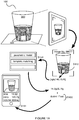
- the method 100 can be implemented by a computing system, examples of which are shown in FIGURES 9-12 , as a fluid receiver analyzer that analyzes a photographic image of a canister (and other fluid receivers) to estimate a quantity and/ or a quality of a fluid contained therein.
- the computer system can be cloud-based (e.g., Amazon EC2), a mainframe computer system, a grid-computer system, or any other suitable computer system.
- the method 100 can be implemented by a handheld (e.g., mobile) computing device, such as smartphone, a digital music player, or a tablet computer executing a native blood component analysis application.
- an image acquisition module integral with the computing device can capture the image of the fluid canister, and a processor integral with the computing device can implement Blocks of the method to extrapolate the quality of the fluid in the canister from the image.
- the computing device can additionally or alternatively communicate with a remote server, such as over the Internet via a wireless connection, the server can perform one or more Blocks of the method 100, and one or more outputs of the method 100 can be transmitted from the remote server back to the computing device for further analysis and/or subsequent presentation to a user (e.g., a nurse, an anesthesiologist).
- the computing device can also include or can be coupled to a digital display, and the method 100 can present information to the user through the display.
- the method 100 can be implemented as a standalone blood volume estimation system including a fluid canister, a fluid canister stand, an image acquisition module, a camera stand configured to support a camera of the image acquisition module adjacent the fluid canister, a digital display, a processor configured to perform at least a portion of the method, and/or a communication module configured to communicate with a remote server that performs one or more Blocks of the method 100.
- the camera can be substantially non-transiently positioned relative to a fluid canister stand such that the camera remains in a suitable position to capture an image of a canister substantially throughout a surgery or other medical event and/ or until the canister is full.
- the blood volume estimation system can thus regularly capture and analyze images of the fluid canister, such as every thirty seconds or every two minutes.
- the blood volume estimation system can further communicate (e.g., via Bluetooth) with another one or more systems implementing any of the methods described in U.S. Pub. Nos. 2013-0011042 , 2013-0303870 , 2013-0301901 , and 2014-0126788 to form a fluid management system for generating a substantially comprehensive estimate of extracorporeal blood volume, total patient blood loss, patient euvolemia status, etc.
- the method can be implemented in or by any other computer system, computing device, or combination thereof.
- variations of the method 100 and system can be adapted to process image data (or other data) derived from any other suitable fluid receiving substrate (e.g., canister, test strip, absorbent pad, surgical textile, sponge, fluid receiving bag, drape, cell salvage system, drain device, etc.) associated with or otherwise coupled to an element configured to provide a region of substantially uniform color and/or an element configured to provide a color gradient, upon reception (e.g., reception into a cavity, reception upon absorption) of a volume of fluid (e.g., urine, saline, ascites, bile, irrigant saliva, gastric fluid, mucus, pleural fluid, interstitial fluid, fecal matter, etc.) at the fluid receiving substrate.
- a volume of fluid e.g., urine, saline, ascites, bile, irrigant saliva, gastric fluid, mucus, pleural fluid, interstitial fluid, fecal matter, etc.
- variations of the method 100 and insert 300 described below can facilitate mitigation of signal saturation (e.g., in relation to fluids with high concentration of a certain component), in determining a concentration and/or an amount of a fluid component within a volume of fluid received at the fluid receiving substrate.
- Block S110 recites: selecting a first region of an image of the canister, the first region of the image exhibiting substantially uniform color.
- Block S110 functions to identify the canister in the image and to select a particular region of the image that exhibits a substantially uniform color (e.g., less than a threshold color change over a particular distance).
- a single region or multiple regions exhibiting substantially uniform color e.g., the same color, different colors
- Block S110 can then include passing this selected region, a mean or median color value of the selected region, or any other feature derived from the selected region to Block S140, which may implement template matching, a regression function or algorithm, or any other suitable model (e.g., a model selected in Block S130) to convert a color parameter in the selected region into an estimated hemoglobin concentration value.
- Block S110 is preferably performed at a module of a computing system configured to receive data associated with an image of the canister and generated by an image acquisition device (e.g., camera module), wherein the computing system can be implemented in one or more of: a mobile computing device, a remote server, a cloud platform, a personal computer, and any other suitable processing device.
- the computing system can implement modules across multiple subsystems; however, the computing system can alternatively be implemented in a single subsystem.
- Block S110 can, however, alternatively be implemented using any other suitable system.
- Block S110 selecting the first region of the image of the canister is preferably performed automatically at a module of the computing system.
- Block S110 can comprise implementing machine vision techniques to identify the first region in the image, and/or one or more positional features associated with the first region in the image.
- Block S110 can comprise implementing one or more of: object localization, segmentation (e.g., edge detection, background subtraction, grab-cut-based algorithms, etc.), gauging, clustering, pattern recognition, template matching, feature extraction, descriptor extraction (e.g., extraction of texton maps, color histograms, HOG, SIFT, etc.), feature dimensionality reduction (e.g., PCA, K-Means, linear discriminant analysis, etc.), feature selection, thresholding, positioning, color analysis, parametric regression, non-parametric regression, unsupervised or semi-supervised parametric or non-parametric regression, and any other type of machine learning or machine vision to identify the first region, and/or positional features that can be used to locate the first region of the image.
- object localization e.g., edge detection, background subtraction, grab-cut-based algorithms, etc.
- gauging clustering
- pattern recognition e.g., template matching
- feature extraction e.g., descriptor extraction (e.g., extraction
- Block S110 can alternatively include manually selecting the first region of the image, for instance, based upon a user input at an input module (e.g., touch pad, touch screen, mouse, etc.) in communication with the computing system.
- an input module e.g., touch pad, touch screen, mouse, etc.
- a user input that selects the first region and/ or indicates a boundary of the first region can alternatively be used in Block S110 to select the first region of the image exhibiting substantially uniform color.
- Block S110 can thus include one or more of: retaining an insert within the canister with a first feature of the insert in a set configuration, such that the insert provides a layer of fluid situated between a wall of the canister and the first feature; coupling an insert to the canister with a first feature of the insert in a configuration that contributes to substantially uniform color across the first region of the canister; generating image data of the canister and the first region of the canister, upon imaging the canister with an image acquisition device; and performing any other suitable action that contributes to selection of the first region within the image of the canister.
- the first region of the image can correspond to an antiglare feature of an element applied or otherwise coupled to the canister, as described in U.S. Pub. No. 2015-0294460 , wherein an antiglare layer of a color grid element extends beyond the color grid element over a portion of the canister, in order to mitigate glare effects within image data of the canister.
- variations of Block S110 can include retaining an insert within the canister with the first feature in a set configuration, and providing alignment between an antiglare region of an element applied to the canister and the first feature in the set configuration, thereby defining the first region of the canister.
- the antiglare layer of the color grid element extends over a portion of the canister and is in alignment with a feature of an insert, within the canister, that provides a layer of fluid between the wall of the canister and the insert (in contributing to uniform color across the first region); however, the first region of the image can be produced and/or detected in any other suitable manner.
- Block S120 which recites: selecting a second region of the image, the second region of the image exhibiting a color gradient.
- Block S120 functions to identify a color gradient across a second region of the image corresponding to fluid within the canister, to characterize the gradient, and to pass this characterization of the color gradient to Block S130.
- Block S120 can include selection of multiple regions of the image, corresponding to multiple color gradients, for subsequent processing in blocks of the method 100.
- Block S120 can generate a metric of the absorption of light by the fluid within the canister (and/or an opacity of the fluid within the canister), in association with a color gradient provided across the second region of the canister, which can be used to assess a level of hemolysis in the canister. Additionally or alternatively, a region of uniform characteristics (e.g., color characteristics) in the image can be used to assess a level of hemolysis in the canister.
- a region of uniform characteristics e.g., color characteristics
- one or more outputs of Block S120 can be implemented in subsequent Blocks of the method 100 to both estimate a hemolysis level in the canister and to compensate for hemolysis in the canister when estimating a total concentration of hemoglobin (e.g., free hemoglobin, intracellular hemoglobin) in the fluid contained therein.
- hemoglobin e.g., free hemoglobin, intracellular hemoglobin
- Block S120 selecting the second region of the image of the canister is preferably performed automatically at a module of the computing system.
- Block S120 can comprise implementing machine vision techniques to identify the second region in the image, and/or one or more positional features associated with the second region in the image.
- a position of the first region of the image, corresponding to a first feature of the insert can be used to derive a position of the second region of the image, corresponding to a second feature of the insert, wherein the second feature of the insert provides the color gradient associated with fluid within the canister, and wherein the second feature has a known configuration relative to the first feature of the insert.
- Block S120 can comprise implementing one or more of: object localization, segmentation (e.g., edge detection, background subtraction, grab-cut-based algorithms, etc.), gauging, clustering, pattern recognition, template matching, feature extraction, descriptor extraction (e.g., extraction of texton maps, color histograms, HOG, SIFT, etc.), feature dimensionality reduction (e.g., PCA, K-Means, linear discriminant analysis, etc.), feature selection, thresholding, positioning, color analysis, parametric regression, non-parametric regression, unsupervised or semi-supervised parametric or non-parametric regression, and any other type of machine learning or machine vision to identify the second region, and/or positional features that can be used to locate the second region of the image.
- object localization e.g., edge detection, background subtraction, grab-cut-based algorithms, etc.
- gauging clustering
- pattern recognition e.g., template matching
- feature extraction e.g., descriptor extraction (e.g., extraction
- Block S120 can alternatively include manually selecting the second region of the image, for instance, based upon a user input at an input module (e.g., touch pad, touch screen, mouse, etc.) in communication with the computing system.
- an input module e.g., touch pad, touch screen, mouse, etc.
- a user input that selects the second region and/or indicates a boundary of the second region can alternatively be used in Block S120 to select the second region of the image exhibiting a color gradient.
- the second region of the image can be associated with a penetration depth of light through fluid within the canister and an absorption coefficient of light associated with fluid within the canister, wherein fluid at a shorter depth within the canister exhibits lighter color, and wherein fluid at a longer depth within the canister exhibits darker color.
- the color gradient can be associated with incident light upon a surface of fluid within the canister (or originating from a feature of an insert within the canister).
- Block S120 can include one or more of: providing incident light at a surface of fluid within the canister; retaining an insert within the canister with a feature of the insert in a configuration that transmits light through fluid within the canister; and performing any other suitable action that contributes to selection of the second region within the image of the canister.
- Block S120 can thus include one or more of: retaining an insert within the canister with a second feature of the insert in a set configuration, such that the insert provides a region of fluid, with a gradient in thickness, situated between a wall of the canister and the second feature; coupling an insert to the canister with a second feature of the insert in a configuration that contributes to the color gradient across the second region of the canister; generating image data of the canister and the second region of the canister, upon imaging the canister with an image acquisition device; and performing any other suitable action that contributes to selection of the second region within the image of the canister.
- the second region of the image can correspond to an antiglare feature of an element applied or otherwise coupled to the canister, as described in U.S. Pub. No. 2015-0294460 , wherein an antiglare layer of a color grid element extends beyond the color grid element over a portion of the canister, in order to mitigate glare effects within image data of the canister.
- variations of Block S120 can include retaining an insert within the canister with the second feature in a set configuration, and providing alignment between an antiglare region of an element applied to the canister and the second feature in the set configuration, thereby defining the first region of the canister.
- the antiglare layer of the color grid element extends over a portion of the canister and is in alignment with a feature of an insert, within the canister, that provides a layer of fluid, with a gradient in thickness, between the wall of the canister and the insert (in contributing to the color gradient across the second region); however, the second region of the image can be produced and/or detected in any other suitable manner.
- Block S120 includes selecting a color gradient initiated at or near the surface of the fluid in the canister and moving downward toward the base of the canister, as shown in FIGURE 2 .
- light incident on the surface of the fluid penetrates the surface of the fluid and is absorbed by the fluid as a function of both depth and an absorption coefficient of the fluid, wherein the absorption coefficient of the fluid is affected by both a concentration of a substance in the fluid and a type or size of the substance (e.g., either a whole red blood cell or free hemoglobin and ruptured cell matter).
- a fluid in a canister may be of substantially uniform concentration with substantially uniform distribution of particulate
- the fluid may appear visually light at the surface of the fluid and darker at a deeper portion of the fluid, with a smooth color gradient between the surface of the fluid and the deeper portion of the fluid.
- Block S120 can thus select all or a portion of this color gradient.
- Block S120 includes identifying a meniscus at the surface of the fluid in the canister (such as described in U.S. Pub. No. 2013-0301901 ) and selects an upper edge of a bounding area of the second region at a particular distance (e.g., 2mm or 20 pixels in the image) inferior to the identified meniscus. Block S120 can then set a lower edge of the bounding area at a fixed distance (e.g., 100mm or 1000 pixels).
- Block S120 can include detecting a region (e.g., a pixel or a set of pixels) of the image below the superior edge of a bounding area at which the color of the fluid darkens by a threshold amount relative to a color of the fluid proximal the superior edge of the bounding area and set the lower edge of the bounding area at this area.
- a region e.g., a pixel or a set of pixels
- Block S120 can thus include selecting a variable bounding area dependent upon fluid diluteness (or any other suitable factor that affects the color gradient), wherein a relatively 'tall' bounded area exhibiting a color gradient is selected for a canister containing a very dilute fluid, and wherein a relatively 'short' bounded area exhibiting a color gradient is selected for a canister containing a high concentration of red blood cells.
- Block S120 can include then connect the superior and inferior edges with vertical edges of a suitable spacing - such as with a spacing of one pixel or ten pixels - to close the bounded area, and then lock or shift the bounded area over the image of the canister, such as centered horizontally over the canister.
- Block S120 can align the bounded area with a region of the canister exhibiting low glare.
- Block S120 can analyze the image to identify an anti-glare surface, coating, or transparent laminate applied to the canister - as described in U.S. Patent Publication No. 2013-0301901 - and then align the bounded area with this anti-glare surface.
- Block S120 can identify a base region of the canister and set the lower edge of the bounded area on or near the base region of the canister and then implement methods as described above to set the upper edge of the bounded area above the lower edge.
- Block S120 can select the second region of the image containing the color gradient in any other suitable way, for instance, by selecting a bounding region for the color gradient at an intermediate portion of the fluid within the canister (i.e., away from the surface of the fluid and away from the base region of the canister).
- the method 100 can also include implementing a light source coupled to, integrated into (e.g., integrated into an insert), or otherwise configured to illuminate fluid within the canister.
- the light source 5 can be coupled to or configured to illuminate a surface of fluid within the canister and/or a surface of the canister, and in variations wherein the light source 5 is coupled to the canister, the light source can be coupled to any suitable portion of the canister (e.g., a wall of the canister, a lid of the canister, an insert coupled to the canister, etc.).
- the canister mounts into a lid supported by a surgical suction machine, wherein the lid includes a laser module configured to direct coherent light into fluid within the canister.
- the laser module can include an output optic directed in a superior-to-inferior direction, thereby transmitting light toward the center of the base of the canister.
- Block S120 of the method 100 can include triggering a laser diode coupled to the laser output optic (e.g., via a fiber optic cable) to output an energy beam, thereby illuminating fluid contained in the canister.
- a florescent or incandescent bulb is arranged over the canister, such as integrated into the lid of the canister or clipped to a rim of the canister (or otherwise configured relative to any other suitable surface of the canister), and the bulb remains 'ON' on during a surgery or is trigged 'ON' (just) before an image of the canister is captured, thereby illuminating the fluid from above (or from any other suitable perspective).
- the canister can include a light source 5 arranged under a base of the canister and directed upward toward the top of the canister, such as along a longitudinal axis of the canister.
- the light source 5, a power source, and a (wired or wireless) controller can be integrated into the base of the canister, and the method 100 executing on a computing device proximal the canister can include transmitting a signal to the controller (e.g., of I2C wired communication protocol or over Bluetooth wireless communication protocol) to trigger the power source to supply power the light source 5.
- the controller e.g., of I2C wired communication protocol or over Bluetooth wireless communication protocol
- an aftermarket fluid illuminator is coupled to the canister, wherein the aftermarket fluid illuminator includes a housing that clips onto or otherwise attaches to an exterior surface of the canister or that rests inside the canister, and wherein a light emitter within the aftermarket fluid illuminator is directed toward the internal volume of the canister and is manually turned “ON" before or during surgery, or is automatically controlled as described above, such as by wirelessly pairing (e.g., over Bluetooth) the aftermarket fluid illuminator with a computing device on which Blocks of the method execute.
- wirelessly pairing e.g., over Bluetooth
- the method can interface with any other light emitter integrated into the canister, installed on or in the canister (e.g., in relation to an insert 300, as described below), attached to the canister, or integrated or installed onto a surgical suction machine supporting the canister during a surgery or other medical event.
- any other light emitter integrated into the canister installed on or in the canister (e.g., in relation to an insert 300, as described below), attached to the canister, or integrated or installed onto a surgical suction machine supporting the canister during a surgery or other medical event.
- the light source can be configured to emit wavelengths of light spanning or otherwise associated with one or more absorbance peaks in an absorbance spectrum for one or more target components of fluid within the canister.
- the light source can be configured to provide a broad range of wavelengths of light, narrower ranges of wavelengths of light, or alternatively a discrete wavelengths of light corresponding to one or more absorbance peaks of a target component of the fluid in the canister.
- the light source 5 can be configured to provide wavelengths of light from ⁇ 400-700nm (e.g., corresponding to an absorbance peak from 500-600nm, corresponding to an absorbance peak at 525nm, corresponding to an absorbance peak at 575nm), and wavelengths of light from 800-950nm (e.g., corresponding to an absorbance peak from 850-900nm, corresponding to an absorbance peak at 870nm).
- ⁇ 400-700nm e.g., corresponding to an absorbance peak from 500-600nm, corresponding to an absorbance peak at 525nm, corresponding to an absorbance peak at 575nm
- 800-950nm e.g., corresponding to an absorbance peak from 850-900nm, corresponding to an absorbance peak at 870nm.
- the light source 5 can be configured to provide wavelengths of light associated with absorbance peaks/spectra of one or more forms of hemoglobin (e.g., oxygenated hemoglobin, sulfhemoglobin, methemoglobin, etc.), in order to enable differentiation in colors of fluid and/or color gradients of fluid associated with different forms of hemoglobin.
- the light source can alternatively be configured to emit wavelengths of light corresponding to absorbance spectra of any other suitable component of fluid within the fluid canister.
- Block S120 can also include identifying a portion of the image corresponding to a point or area on which light from an adjacent light source is initially incident on the fluid and select the second region of the image - exhibiting a color gradient - that extends from this point or area.
- Block S120 can include initially identifying the canister in the image, identifying a portion of the image corresponding to an anti-glare surface on the canister, testing individual pixels or clusters of pixels within this portion of the image for a greatest brightness, and identifying a particular individual pixel or cluster of pixels of greatest brightness in this portion of the image as the initial point of incidence of light on the fluid.
- Block S120 can then include selecting the second region - including the color gradient - that extends from this particular pixel or pixel cluster, such as by selecting a portion of the image extending downward from the particular pixel or pixel cluster associated with the light source that is known to be arranged above the canister, or by selecting a portion of the image extending upward from the particular pixel or pixel cluster associated with a light source 5 that is known to be arranged under a base of the canister.
- Block S120 can function in any other way to select the second region of the image that includes a color gradient corresponding to absorption of light from an external light source by fluid in the canister.
- Block S110 can then include selecting the first region of the image distinct from the second region and exhibiting a substantially uniform color (e.g., in terms of hue, saturation/chroma, and brightness/value).
- Block S120 can include selecting a region of the image coincident with an anti-glare surface on the canister and substantially removed from the second region.
- Block S120 can quantify absorption of light downward from the surface of the fluid as a percentage of light absorption (or intensity of incident light), and Block S110 can bound a top edge of the first region at a horizontal line of pixels offset (e.g., by 10 pixels) downward from a particular pixel vertically below a point of initial light incidence on the surface of the fluid and associated with a point of 99% absorption of light from a (local or ambient) light source (or 1% intensity of the initial intensity of the incident light).
- a horizontal line of pixels offset e.g., by 10 pixels
- Block S110 can analyze the image to identify a portion of the image corresponding to fluid within the canister and then identify a largest area of contiguous pixels (or pixel clusters) with less than a threshold difference in value (e.g., less than a 2% change in color value in the red spectrum, less than a 4% change in color value in the green spectrum, and less than a 5% change in color value in the blue spectrum).
- a threshold difference in value e.g., less than a 2% change in color value in the red spectrum, less than a 4% change in color value in the green spectrum, and less than a 5% change in color value in the blue spectrum.
- Block S110 can identify a region of the image of a target dimension (e.g., 50 pixels by 50 pixels) and/ or target size (e.g., 200 contiguous pixels) exhibiting less than a threshold change in color, shade, or tint.
- Block S110 can function in any other way to select the first region of the image exhibiting a substantially uniform color in any other suitable way. Furthermore, in relation to the first variation, involving a co-axial color gradient, Blocks S110 and S120 can be performed in any other suitable order and in any other suitable alternative manner.
- Block S110 includes selecting the first region of the image that corresponds to a layer of fluid between a wall of the canister and a first feature within the canister, along a line of sight between the canister and a camera or (other optical sensor of an image acquisition device) that captures the image.
- Block S120 can include selecting the second region of the image that corresponds to a region of fluid, having a gradient in thickness, between a wall of the canister and a second feature within the canister, along the line of sight, as shown in FIGURES 1A and 1B .
- the first feature in this second variation is offset from the wall of the canister at a substantially uniform distance such that a "layer" of fluid between the wall of the canister and the first feature is of substantially uniform thickness across the first feature, and the second feature tapers away from the wall of the canister such that the total "thickness" of "layers” of fluid between the wall of the canister and the second feature increases with a known profile (e.g., linear profile, non-linear profile, stepwise function profile, etc.), such as relative to an edge of the second feature nearest the image acquisition module.
- a known profile e.g., linear profile, non-linear profile, stepwise function profile, etc.
- the first feature 310 and/or the second feature 320 can be coupled to an insert 300 configured to be retained within the canister 200 in a first operation mode, with the first feature 310 and/or the second feature 320 in a set configuration relative to the canister. Furthermore, as shown in FIGURE 3A , retention of the insert 300 within the canister 200 can be permanent or reversible, for instance, by way of a locking feature (e.g., of the canister 200 and/or of the insert 300) that irreversibly or reversibly locks the insert 300 in a set configuration within the canister 300.
- a locking feature e.g., of the canister 200 and/or of the insert 300
- Variations of the locking feature 305 can include one or more of: a protrusion 306 (e.g., rail, etc.) on at least one of the canister 200 and the insert 300, that mates with a recess (e.g., slot, etc.) on the other one of the insert 300 and the canister 200; magnetic features (e.g., complementary magnets coupled to the insert 300 and the canister); a mechanical press fit mechanism between a portion of the canister 200 and a portion of the insert; a mechanical snap fit between a portion of the canister 200 and a portion of the insert; and any other suitable locking feature 305.
- a protrusion 306 e.g., rail, etc.
- a recess e.g., slot, etc.
- magnetic features e.g., complementary magnets coupled to the insert 300 and the canister
- a mechanical press fit mechanism between a portion of the canister 200 and a portion of the insert
- a mechanical snap fit between a portion of the canister 200
- the first feature 310 and/or the second feature may alternatively not be a feature of an insert 300, and can be of unitary construction with an internal portion of the canister 200.
- some variations of the canister 200 and/or the insert 300 can omit a second feature 320, and only include a first feature 310 configured to define a region of substantially uniform color within an image of the canister.
- the insert 300 is preferably composed of a material that is white, opaque, and impermeable to fluid within the canister, in order to provide the region of uniform color and/ or the color gradient region.
- the insert 300 can alternatively be composed of a material that is one or more of: non-white, non-opaque (e.g., having some degree of transparency), and not impermeable to fluid within the canister.
- the insert 300 can have a color (e.g., non-white color) or pattern (e.g., grid, matrix barcode, QR code) that is observable through the region of fluid between the insert 300 and the canister 200, in supporting subsequent blocks of the method 100.
- the pattern can be coupled to a portion of the insert 300 in direct contact with an inner surface of the canister, or can alternatively be coupled to a portion of the insert 300 not in direct contact with an inner surface of the canister.
- a color grid or matrix barcode coupled to the insert and observable through the region of fluid between the insert 300 and the canister 200 can be used to determine fluid parameters (e.g., fluid component concentrations) associated with fluid within the canister 200.
- fluid parameters e.g., fluid component concentrations
- a color grid including a set of regions of color, each region associated with a blood component concentration can be applied to the insert.
- an inability of a detection system to identify one or more color regions of the color grid, through fluid within the canister can be used to determine a blood component concentration associated with fluid within the canister.
- a detection system can identify a color region on the insert 200, that is unobservable through fluid within the canister, associate the color region with a blood component concentration, and determine an amount of the blood component within the canister 200 based upon a volume of fluid within the canister.
- an analysis of a difference in color between each color region, observed through fluid within the canister, and a color of fluid within the canister can be used to similarly estimate a blood component concentration for fluid within the canister.
- a color "grid” exhibiting a gradient in color can be used to assess a level of hemolysis, in relation to a gradient in color within fluid of the canister.
- the light source 5 can be integrated within the insert 300 or otherwise coupled to the insert 300, as shown in FIGURE 3B , in order to transmit light through fluid within the canister 200.
- the insert 300 can be composed of, or include features composed of a material configured to transmit light from the light source 5 in a desired manner.
- the material can function as a light pipe (e.g., as in fiber optics), configured to direct light from the light source 5 along and/ or to a surface of the insert 200 in contact with fluid within the canister 200.
- the material of the insert 300 can be configured to transmit light from the light source 5 in a diffuse manner through fluid within the canister 300.
- the light source 5 and/or the insert 300 be configured in any other suitable manner.
- Features of the insert 300 can, however, enhance implementation of the method 100 in any other suitable manner.
- the insert 300 includes a first alignment arm 305a and a second alignment arm 305b, each including a slot that complements an associated protrusion 306a, 306b configured at an internal surface of the canister 200, wherein the first and the second alignment arms 305a, 305b and the protrusions 306a, 306b function as a locking feature 305.
- the first and the second alignment arms 305a, 305b surround (e.g., sandwich) a first feature 310a of the insert configured to provide the region of uniform color, wherein the first feature 310a has a surface displaced from an internal surface of the canister 200 by a constant distance.
- the first alignment arm 305a and the second alignment arm 305b are radially displaced from each other in surrounding the first feature 310a, and the insert 300a has an axis of symmetry, such that the position of the first alignment arm 305a mirrors the position of the second alignment arm 305b about the first feature 310a.
- a superior edge of the first feature 310a includes a lip 311 configured to contact an adjacent internal portion of the canister 200, wherein the lip 311includes an alignment flange 312 configured to facilitate alignment between the canister 200 and the insert 300a.
- the lip 311 further functions to block light rays that could otherwise penetrate the imaging region associated with the first feature 310a of the canister 200 and confound any measurements.
- color features extracted from the imaging region are derived from backscattering or ambient light (which is accounted for, for instance, by a color grid as in U.S. Publication No. 2015-0294460 ), and backlighting from the first feature 310a of the insert 300a.
- Variations of the first implementation of the insert 300a can, however, omit a lip 311, and image processing methods can account for any light rays that penetrate the imaging region associated with the first feature, in relation to the insert 300a without a lip 311.
- the insert 300 of the first implementation further includes a set of gaps 313a, 313b, 313c configured to allow fluid within the canister 200 to flow into the first feature 310a.
- a first gap 313a is configured laterally between the first alignment arm 305a and the first feature 310a
- a second gap 313b is configured laterally between the second alignment arm 305b and the insert; however, in alternative variations of the first implementation, the set of gaps 313a, 313b, 313c can be configured in any other suitable manner.
- the insert 300a of the first implementation includes a grip handle 315 configured at a posterior portion of the insert 300a that enables the user or another entity to position the insert 300 within the canister 200, and apply a "downward" force to push the insert toward the base of the canister 200.
- an insert 300b defining the first feature 310b and the second feature 320b is configured to be installed in the canister 200 prior to use in receiving bloodied fluid from a patient.
- the insert 300b defines a frustoconical structure 320b with a cylindrical base 310b that snaps into the base of the canister 200, as shown in FIGURE 5 , wherein the insert 300b is manufactured from a highly-reflective (i.e., glossy) white polymer material and/or is coated with a white glossy material.
- the outer surface of cylindrical base 310b is displaced from an interior surface of the canister 200 when the insert 300b is installed therein, such as by ⁇ 6mm (e.g., an average of 6 mm), such that a layer of fluid between the interior surface of the canister 200 and the cylindrical base 310b yields a substantially uniform color in the corresponding region of the image of canister; Block S110 can thus identify and select this region of the image.
- ⁇ 6mm e.g., an average of 6 mm
- the frustoconical structure 320b can taper toward a center portion of the canister 200 (e.g., at a slope of 0.5 or at an angle of 30°) in an inferior to superior direction, thereby yielding a color gradient in a portion of the image corresponding to a region of fluid between the interior surface of the canister 200 and the frustoconical structure 320b, as less ambient light reaches and is reflected back from the frustoconical structure 320b, and as the thickenss of the fluid region between the interior wall of the canister and the frustoconical structure increases;
- Block S120 can thus identify and select this region of the image.
- Blocks S110 and S120 can also cooperate to identify an edge between the frustoconical structure and the cylindrical base and then distinguish between the frustoconical structure and the cylindrical base based upon a color gradient and color uniformity on each side of the edge.
- the first feature 310c defines a first vertical surface (e.g., planar surface, curved surface) that faces (e.g., squarely faces) and is offset from the interior wall of the canister, such as by ⁇ 6mm
- the second feature 320c defines a second vertical surface tapering away from (e.g., with a linear profile, with a non-linear profile) an interior surface of the canister 200, the first and second features 310c cooperating to define a sharp vertical edge, as shown in FIGURE 6 .
- the substantially uniform thickness of a layer of fluid between the interior surface of the canister 200 and the first feature 310c can yield a substantially uniform color in the corresponding region of the image
- the increasing thickness of the region of fluid between the interior surface of the canister 200 and the second feature 320c along the length of the second feature 320c can yield a color gradient across the corresponding region of the image.
- the insert 300d can include a elongated member defining a sawtooth cross-section with a (substantially) planar at the tip of each tooth, as shown in FIGURE 7 , wherein the each planar tip defines a first feature 310d, and wherein the taper of each sawtooth defines a second feature 320d.
- this geometry of the insert 300d can provide multiple first and second features 310d, 320d that yield multiple corresponding regions of substantially uniform color and multiple corresponding regions exhibiting color gradients such that, despite a volume of fluid in the canister and/or an amount of undissolved solids in the canister, Blocks S110 and S120 can identify and select at least one suitable first region and one suitable second region, respectively, in the image of the canister.
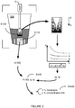
- the insert 300e can include stepped configuration defined by a set of first features 310e, as shown in FIGURE 8 , wherein each of the set of first features 310e is offset from an internal surface of the canister 200 by a certain distance (e.g., in order to provide a region of uniform color, with a region of fluid between the surface of the canister and each of the first features of the insert).
- each of the set of first features 310e is further displaced from an adjacent first feature by a distance (e.g., with uniform spacing, with non-uniform spacing), such that collectively, the set of first features 310e defines a second feature 320e that provides a color gradient along a dimension of the insert 300e.
- the set of first features 310e can be arranged such that the first features 310e traverse deeper into the canister in an inferior to superior direction, arranged such that the first features 310e traverse deeper into the canister in a superior to inferior direction, or alternatively traverse deeper or shallower in relation to a surface of the canister in any other suitable configuration.
- Blocks S110 and S120 can identify and select at least one suitable first region and one suitable second region, respectively, in the image of the canister.
- Blocks S110 and/or S120 can include selecting and analyzing regions corresponding to each of the set of first features 310e, in order to extract a parameter (e.g., color parameter) from each region, as shown in FIGURE 8 .
- a parameter e.g., color parameter
- Each parameter e.g., f1, f2, f3,...,fn
- can then be processed e.g., with a color model, as described above, in order to determine a concentration of a blood component associated with fluid within the canister.
- each parameter e.g., f1, f2, f3,...,fn
- can be used to classify fluid within the canister into one of a set of regimes e.g., a high concentration regime, a medium concentration regime, a low concentration regime, one of a set of hemolysis regimes, etc.
- a subset of the set of parameters e.g., only f2-f4 are used to determine one or more characteristics of the fluid within the canister 200 using a discrete model.
- a bulk solution color feature can be compared to a color feature associated with a portion of an insert 300 (e.g., a ratio can be determined, a difference can be determined, etc.), wherein one or more of the bulk solution color feature and the color feature associated with the insert can be used to determine an amount of a fluid component within the canister.
- comparison and/or color features can be used to classify fluid within the canister into one of a set of regimes, as described above, in order to select one of a set of color models to characterize fluid within the canister.
- Processing parameters derived from the insert 300e of the fifth implementation and variations thereof can, however, be performed in any other suitable manner.
- the insert can be of any other suitable material, surface finish, and/or color and can define a first feature and a second feature of any other suitable form.
- Blocks S110 and S120 can also function in any other way to identify a first region of the image of substantially uniform color and a second region exhibiting a color gradient in any other suitable way.
- Blocks S110 and S120 can also select multiple instances of first and second regions, respectively. For example, Block S120 can select a "second region" corresponding to a color gradient arising from ambient light incident on a surface of the fluid and another "second region" corresponding to a tapered feature of an insert 300 installed within the canister 200.
- variations of the above implementations can be combined in any suitable manner.
- Block S140 recites: determining a concentration of the blood component in the canister based upon a color parameter representative of the first region of the image.
- Block S140 can include implementing one or more of a parametric model and a template matching algorithm to determine the concentration of the blood component associated with fluid within the canister.
- Block S140 can implement a parametric model to determine the concentration of the blood component (e.g., hemoglobin) within the sample, wherein the parametric model implements a support vector machine (SVM) algorithm with a radial basis function (RBF) kernel that generates a hemoglobin concentration derived from red value, green value, and blue value color intensities representative of the first region of the image, and multiplies the hemoglobin concentration by the volume of fluid within the canister can to determine the estimated hemoglobin mass.
- SVM support vector machine
- RBF radial basis function
- any other suitable parametric model e.g., linear regression model, power curve driven regression model, other regression model, etc.
- a non-parametric model can be implemented by the processing system to determine an amount of any other suitable blood component within the canister (or other fluid receiver).
- Block S140 can further include determining a hemolysis status of fluid within the canister, which functions to enhance outputs of the method 100 with information pertaining to quality of the fluid contained within the canister (e.g., in relation to usability for transfusion, etc.).
- Block S140 can include receiving information indicative of a concentration of free hemoglobin and a concentration of intracellular hemoglobin present in fluid within the canister, thereby enabling determination of a distribution of free hemoglobin vs. intracellular hemoglobin within the canister.
- Block S140 can include receiving information pertaining to the hemolysis status from an entity interacting with the system, wherein information pertaining to free hemoglobin vs.
- intracellular hemoglobin can be manually input (e.g., with keypad strokes, by speech, etc.) into an input module of a computing device of the system.
- a holistic blood loss management application executing at a mobile computing device can include a user interface configured to receive an input indicative of the hemolysis status within the canister, wherein the input is provided by a physician, nurse, assistant, or technician present within an operating room environment.
- a free hemoglobin concentration and/or an intracellular hemoglobin concentration can be processed with volume information in Blocks S150 and S151, in order to determine an amount hemoglobin present within fluid in the canister, as well as an amount of free vs. intracellular hemoglobin present within fluid in the canister.
- a second region of the image corresponding to a color gradient (e.g., as in Block S120), can be used to estimate a hemolysis status of fluid within the canister, as described in Blocks S130 and S140b below. Then, in a manner similar to that described in Block S140 above, outputs of Block S140b concentration can be processed with volume information in Blocks S150 and S151, in order to determine an amount hemoglobin present within fluid in the canister, as well as an amount of free vs. intracellular hemoglobin present within fluid in the canister.
- Block S130 which recites: selecting a canister content model based on a characterization of the color gradient in the second region of the image.
- Block S130 selects a single line of pixels along the second region, decomposes the color of each pixel in the line into red, green, and blue components, plots a brightness in the red component space for each pixel, and calculates a line of best fit for the plotted values.
- Block S130 can fit an exponential curve to a line of pixels in a co-axial color gradient as selected in the first variation described above, and Block S130 can fit a logarithmic curve to a line of pixels in a cross-axial color gradient as selected in the second variation described above.
- Block S130 can group adjacent pixels within the second region of the image into clusters, average or otherwise synthesize color values within each cluster of pixels, decompose the color of each pixel cluster into the line into red, green, and blue components, plot a brightness (or color) in the red component space for each pixel cluster, and calculate a line of best fit for the plotted brightness values.
- a database can include models A, B, C, D, and E, wherein model A covers a hemolysis range of 0-20% and corresponds to 'a' coefficient values of a ⁇ 10, wherein model B covers a hemolysis range of 20-40% and corresponds to 'a' coefficient values of 10 ⁇ a ⁇ 14, wherein model C covers a hemolysis range of 40-60% and corresponds to 'a' coefficient values of 14 ⁇ a ⁇ 19, wherein model D covers a hemolysis range of 60-80% and corresponds to 'a' coefficient values of 19 ⁇ a ⁇ 22, and wherein model E covers a hemolysis range of 80-100% and corresponds to 'a' coefficient values of 22 ⁇ a.
- Block S130 can select Model D and estimate a hemolysis level in the canister at between 60% and 80%.
- Block S130 can calculate an absorption coefficient of the fluid from the color gradient and pass this value directly to Block S140b or select a canister content model corresponding to this absorption coefficient.
- Block S130 can additionally or alternatively determine a sharpness parameter associated with a junction (i.e., an edge) between the first and second features, as described above, and process the sharpness parameter according one or more of: a particular algorithm, a parametric model, a series of template images, and any other suitable model or algorithm.
- a sharpness parameter associated with a junction i.e., an edge
- a particular algorithm i.e., a parametric model
- a series of template images i.e., a series of template images
- Block S130 can thus select the algorithm, parametric model, or series of template images, accordingly.
- Block S140b can pass a color parameter (e.g., redness value) of the first region of the image into the algorithm, parametric model, or series of template images to output an estimate of the hemoglobin concentration and/or the hemolysis status of hemoglobin contained in the canister.
- a color parameter e.g., redness value
- Block S130 can extract a color parameter (e.g., a redness value) from the first region of the image - such as described in U.S. Patent Publication No. 2013-0301901 - and select a particular algorithm, parametric model, or series of template images, etc. based on this color value.
- Block S140b can then pass a metric derived from the color gradient into the selected algorithm, parametric model, or series of template images, etc. to output an estimate of the hemoglobin concentration and/or the hemolysis status of hemoglobin contained in the canister.
- Block S130 can extract one or more quantitative values of the color gradient from the second region selected in Block S120, and Block S140b can pass both a color value of the first region and the quantitative value(s) of the color gradient into a standardized parametric model to output an estimate of the hemoglobin concentration and/ or the hemolysis status of hemoglobin contained in the canister.
- Block S130 can function in any other way to extract relevant data from the color gradient in the second region of the image and/or to selecting a particular model, algorithm, or template image set suitable for estimating a quantity and/or quantity of hemoglobin in the canister.
- Block S140b recites: estimating a concentration of a blood component and a hemolysis status of fluid within the canister based on a color in the first region of the image and the canister content model.
- Block S140b implements methods and techniques described in U.S. Patent Publication No. 2013-0301901 to correlate a color value in the image of the canister to a hemoglobin concentration (and/or a concentration of another blood component) in the canister.
- Block S140b can further output a metric indicative of a quality of the hemoglobin (or other blood component) in the canister, based upon an estimation of hemolysis status.
- Block S130 selects a generic multivariable parametric model
- Block S140b applies an average redness value in the red component space of the first region of the image and an absorption coefficient of the fluid and/or a coefficient of a line of best fit of the color gradient analyzed in Block S130 to a multivariable parametric model, in order to solve for a concentration of hemoglobin the canister and percentage of free hemoglobin (or a percentage of lysed red blood cells, a ratio of free hemoglobin to intracellular hemoglobin, etc.) in the canister.
- Block S130 can select a particular set of template images - from a multitude of template images - of canisters containing fluids of known hemoglobin concentrations and hemolysis levels, and exhibiting substantially similar light absorption coefficients as the current canister.
- Block S140b can thus implement template matching to match the first region of the image to a particular template image of a template canister containing a volume of fluid of known hemoglobin concentration and hemolysis level. Block S140b can thus output the known hemoglobin concentration and hemolysis level of the template canister as an estimate of the hemoglobin concentration and hemolysis level of the current canister.
- Blocks S110, S120, S130, and S140b can cooperate in any other suitable way to estimate the concentration of hemoglobin (and the hemolysis level) of the canister.
- one variation of the method further includes Block S150, which recites: determining a volume of fluid within the canister, and Block S151, which recites: generating an analysis informative of an amount of the blood component within the canister, based upon the concentration of the blood component and the volume of fluid within the canister.
- Blocks S150 and S151 can include: within an image of a canister, identifying a reference marker on the canister, selecting an area of the image based on the reference marker, correlating a portion of the selected area with a fluid level within the canister, estimating a volume of fluid within the canister based on the fluid level, and estimating a mass of hemoglobin within the canister based on the estimated volume and the concentration of the hemoglobin in the canister.
- Block S150 can implement methods and techniques described in U.S. Patent Publication No. 2013-0301901 to detect the volume of fluid in the canister and to calculate the total volume, mass, weight, or other method of hemoglobin in the canister based on the total volume and the estimated blood component concentration in the canister.
- Blocks S150 and S151 can include receiving information pertaining to the volume of fluid within the canister by an entity interacting with the system.
- the volume of fluid within the canister can be manually input (e.g., with keypad strokes, by speech, etc.) into an input module of a computing device of the system.
- a holistic blood loss management application executing at a mobile computing device e.g., tablet computer, smartphone device, etc.
- a user interface configured to receive an input indicative of the volume of fluid within the canister, wherein the input is provided by a physician, nurse, assistant, or technician present within an operating room environment.
- the Block S150 can thus use the input volume of fluid information in estimating a quantity of the blood component within the canister.
- the quantity of the blood component within the canister can be determined in any other suitable manner.
- Blocks S150 and S151 can implement methods and techniques described in U.S. Patent Application No. 14/072,625 to detect the volume of fluid in the canister and to calculate the total volume, mass, weight, or other method of the blood component in the canister based on the total volume and the estimated blood component concentration in the canister.
- Block S150 can then deliver prompts or other notifications to a user to salvage red blood cells from the canister if the amount of intra-cellular hemoglobin (or if the ratio of intra-cellular hemoglobin to free hemoglobin) exceeds a minimum threshold.
- Block S150 can similarly deliver a prompt to the user to not salvage red bloods cells from the canister if the amount of intra-cellular hemoglobin (or if the ratio of intra-cellular hemoglobin to free hemoglobin) falls short of the minimum threshold, such as described in U.S. Patent Publication No. 2014-0126788 . Additionally or alternatively, outputs of Block S150 can be used to provide information pertaining to blood loss parameters of a patient to an entity (e.g., at an electronic computing device comprising a display configured to render the information).
- an entity e.g., at an electronic computing device comprising a display configured to render the information.
- the systems and methods of the preferred embodiment can be embodied and/or implemented at least in part as a machine configured to receive a computer-readable medium storing computer-readable instructions.
- the instructions are preferably executed by computer-executable components preferably integrated with the application, applet, host, server, network, website, communication service, communication interface, hardware/firmware/software elements of a user computer or mobile device, or any suitable combination thereof.
- Other systems and methods of the preferred embodiment can be embodied and/or implemented at least in part as a machine configured to receive a computer-readable medium storing computer-readable instructions.
- the instructions are preferably executed by computer-executable components preferably integrated by computer-executable components preferably integrated with apparatuses and networks of the type described above.
- the computer-readable medium can be stored on any suitable computer readable media such as RAMs, ROMs, flash memory, EEPROMs, optical devices (CD or DVD), hard drives, floppy drives, or any suitable device.
- the computer-executable component is preferably a processor but any suitable dedicated hardware device can (alternatively or additionally) execute the instructions.
Claims (15)
- Procédé (100) d'estimation d'une quantité d'un composant sanguin dans un volume de fluide à l'intérieur d'un réservoir (200), comprenant :au niveau d'un système de calcul en communication avec un dispositif d'acquisition d'images, la réception de données associées à une image du réservoir (200) générée par le dispositif d'acquisition d'images ;au niveau du système de calcul, la sélection automatique d'une première région de l'image (S110) présentant une couleur pratiquement uniforme, la première région de l'image correspondant à une couche de fluide située entre une région transparente ou translucide d'une paroi du réservoir (200) et un premier élément d'un insert (300) retenu à l'intérieur du réservoir (200) de telle façon que le premier élément est décalé d'une distance constante de la paroi du réservoir (200) ;au niveau du système de calcul, la détermination d'un paramètre de couleur représentatif de la première région de l'image ;au niveau du système de calcul, la détermination d'une concentration d'un composant sanguin à l'intérieur du réservoir (200), sur la base du paramètre de couleur (S140) ;lors de la détermination du volume de fluide à l'intérieur du réservoir (S150), la génération d'une analyse informative d'une quantité du composant sanguin à l'intérieur du réservoir (S151) ; etau niveau d'un dispositif de sortie en communication avec le système de calcul, la fourniture d'une information dérivée de l'analyse à une entité associée à un individu chez qui le volume de fluide a été obtenu.
- Procédé selon la revendication 1, comprenant en outre la rétention de l'insert à l'intérieur du réservoir avant la réception de fluide provenant du patient dans le réservoir, dans lequel la rétention de l'insert à l'intérieur du réservoir comprend la réalisation d'un alignement entre le premier élément de l'insert et une couche antireflet d'une grille de couleurs couplée à une surface extérieure du réservoir.
- Procédé selon la revendication 1, comprenant en outre la détermination du volume de fluide à l'intérieur du réservoir en réalisant l'une au moins parmi : 1) la réception d'une information relative au volume de fluide à l'intérieur du réservoir au niveau d'un dispositif d'entrée en communication avec le système de calcul, et 2) l'identification d'un marqueur de référence sur le réservoir, la sélection d'une zone de l'image sur la base du marqueur de référence, la détermination d'un niveau de fluide à l'intérieur du réservoir basée sur une partie de la zone, et l'estimation du volume de fluide à l'intérieur du réservoir sur la base du niveau de fluide.
- Procédé selon la revendication 1, comprenant en outre : au niveau du système de calcul, la sélection automatique d'une deuxième région de l'image présentant un gradient de couleur, et la détermination de l'un au moins parmi la concentration du composant sanguin à l'intérieur du réservoir et un état d'hémolyse du fluide à l'intérieur du réservoir sur la base de la deuxième région de l'image.
- Procédé selon la revendication 4, comprenant en outre la transmission de lumière, à partir d'une source de lumière, à travers le fluide à l'intérieur du réservoir afin d'induire ainsi le gradient de couleur, dans lequel la lumière est caractérisée par au moins une longueur d'onde entre une ou plusieurs des valeurs 400-700 nm et 800-950 nm par rapport à l'absorption de lumière par l'hémoglobine, et dans lequel la détermination de l'état d'hémolyse se fait sur la base des signaux générés par un dispositif d'acquisition d'images extérieur au réservoir.
- Procédé selon la revendication 4, comprenant en outre la rétention d'un deuxième élément de l'insert à l'intérieur du réservoir de telle façon que le deuxième élément fournit une région avec un gradient d'épaisseur de fluide entre le deuxième élément et la paroi du réservoir.
- Procédé selon la revendication 6, dans lequel le deuxième élément comprend un ensemble de premiers éléments disposés dans une configuration étagée, chaque élément de l'ensemble de premiers éléments étant décalé de la paroi du réservoir, et dans lequel le procédé comprend en outre : la génération d'un paramètre à partir de chaque élément de l'ensemble de premiers éléments ; la classification du fluide suivant un régime de concentrations d'un ensemble de régimes de concentrations sur la base des paramètres générés à partir de l'ensemble de premiers éléments ; et la détermination de la concentration du composant sanguin à l'intérieur du réservoir sur la base du régime de concentrations.
- Système d'estimation d'une concentration d'un composant d'un fluide, le système comprenant :un récipient pour recevoir un volume de fluide provenant d'un patient ;un insert configuré pour être retenu à l'intérieur du récipient de telle façon qu'un premier élément de l'insert est décalé d'une distance constante d'une région transparente ou translucide d'une paroi du récipient, etun système de calcul en communication avec un dispositif d'acquisition d'images et comprenant :un premier module configuré pour recevoir un ensemble de données d'images du récipient générées par le dispositif d'acquisition d'images ;un deuxième module configuré pour sélectionner automatiquement une première région de l'image présentant une couleur pratiquement uniforme et correspondant au fluide entre la région transparente ou translucide de la paroi du récipient et le premier élément de l'insert ;un troisième module configuré pour déterminer un paramètre représentatif de la première région de l'image ; etun quatrième module configuré pour déterminer une concentration d'un composant d'un fluide à l'intérieur du récipient, sur la base du paramètre.
- Système selon la revendication 8, comprenant en outre un dispositif de sortie en communication avec le système de calcul, et configuré pour délivrer une information dérivée de l'analyse à une entité associée à un individu chez qui le volume de fluide a été obtenu, dans lequel le dispositif de sortie est intégré avec le dispositif d'acquisition d'images.
- Système selon la revendication 8, dans lequel l'insert comporte un élément d'alignement qui couple l'insert au récipient.
- Système selon la revendication 10, dans lequel l'insert comporte une base cylindrique à une extrémité inférieure de l'insert et une partie tronconique supérieure à la base cylindrique, dans lequel la base cylindrique définit le premier élément et dans lequel la partie tronconique définit un deuxième élément configuré pour fournir un gradient de couleur lors de la réception de fluide dans le récipient.
- Système selon la revendication 10, dans lequel l'insert comporte un ensemble de premiers éléments disposés dans une configuration étagée, chaque élément de l'ensemble de premiers éléments étant décalé de la paroi du récipient et d'un premier élément adjacent.
- Système selon la revendication 12, dans lequel le troisième module du système de calcul est configuré pour générer un paramètre à partir de chaque élément de l'ensemble de premiers éléments ; pour classifier le fluide suivant un régime de concentrations d'un ensemble de régimes de concentrations sur la base des paramètres générés à partir de l'ensemble de premiers éléments ; et pour déterminer la concentration du composant d'un fluide à l'intérieur du récipient sur la base du régime de concentrations.
- Système selon la revendication 8, comprenant en outre un module d'éclairage en communication avec le récipient, dans lequel le module d'éclairage est configuré pour transmettre de la lumière à travers le fluide à l'intérieur du récipient, dans lequel le module d'éclairage comprend une source de lumière configurée pour transmettre de la lumière caractérisée par au moins une longueur d'onde entre une ou plusieurs des valeurs 400-700 nm et 800-950 nm par rapport à l'absorption de lumière par l'hémoglobine.
- Système selon la revendication 14, dans lequel le module d'éclairage est couplé à un insert retenu à l'intérieur du récipient.
Applications Claiming Priority (3)
| Application Number | Priority Date | Filing Date | Title |
|---|---|---|---|
| US201461980027P | 2014-04-15 | 2014-04-15 | |
| US201462080927P | 2014-11-17 | 2014-11-17 | |
| PCT/US2015/026042 WO2015161003A1 (fr) | 2014-04-15 | 2015-04-15 | Procédé d'estimation d'une quantité d'un composant sanguin dans un réservoir de fluide |
Publications (3)
| Publication Number | Publication Date |
|---|---|
| EP3132253A1 EP3132253A1 (fr) | 2017-02-22 |
| EP3132253A4 EP3132253A4 (fr) | 2017-10-18 |
| EP3132253B1 true EP3132253B1 (fr) | 2019-02-13 |
Family
ID=54265497
Family Applications (1)
| Application Number | Title | Priority Date | Filing Date |
|---|---|---|---|
| EP15780590.4A Active EP3132253B1 (fr) | 2014-04-15 | 2015-04-15 | Procédé d'estimation d'une quantité d'un composant sanguin dans un réservoir de fluide |
Country Status (4)
| Country | Link |
|---|---|
| US (1) | US9773320B2 (fr) |
| EP (1) | EP3132253B1 (fr) |
| JP (3) | JP6652499B2 (fr) |
| WO (1) | WO2015161003A1 (fr) |
Families Citing this family (24)
| Publication number | Priority date | Publication date | Assignee | Title |
|---|---|---|---|---|
| US10426356B2 (en) | 2011-07-09 | 2019-10-01 | Gauss Surgical, Inc. | Method for estimating a quantity of a blood component in a fluid receiver and corresponding error |
| US9652655B2 (en) | 2011-07-09 | 2017-05-16 | Gauss Surgical, Inc. | System and method for estimating extracorporeal blood volume in a physical sample |
| US9936906B2 (en) | 2012-05-14 | 2018-04-10 | Gauss Surgical, Inc. | System and methods for managing blood loss of a patient |
| JP6652499B2 (ja) | 2014-04-15 | 2020-02-26 | ガウス サージカル, インコーポレイテッドGauss Surgical, Inc. | 流体キャニスター内の血液成分の量を推定するための方法 |
| US11504037B2 (en) | 2015-05-15 | 2022-11-22 | Gauss Surgical, Inc. | Systems and methods for assessing fluids from a patient |
| US10789710B2 (en) | 2015-05-15 | 2020-09-29 | Gauss Surgical, Inc. | Methods and systems for characterizing fluids from a patient |
| US11030475B2 (en) * | 2015-07-08 | 2021-06-08 | Zest Labs, Inc. | Photo analytics calibration |
| JP6968427B2 (ja) * | 2015-12-23 | 2021-11-17 | ガウス サージカル, インコーポレイテッドGauss Surgical, Inc. | ある体積の流体における血液成分の量を推定するためのシステム及び方法 |
| WO2017190069A1 (fr) * | 2016-04-28 | 2017-11-02 | Gorr Bryan | Surveillance de condition de fluide automatique multi-capteurs, émetteur-récepteur et concentrateur d'affichage d'état |
| CA3031081C (fr) * | 2016-07-18 | 2021-08-31 | Siemens Healthcare Diagnostics Inc. | Systeme et procede de detection optique totale d'hemolyse de sang |
| US20180106659A1 (en) * | 2016-10-15 | 2018-04-19 | Centech Corp. | Automated volumetric measurement and verification system |
| RU2762936C2 (ru) | 2016-10-28 | 2021-12-24 | Бекман Каултер, Инк. | Система оценки подготовки вещества |
| US10401347B2 (en) | 2017-01-11 | 2019-09-03 | Cypher Medical, Llc | Method of estimating blood volume |
| US10154885B1 (en) | 2017-05-26 | 2018-12-18 | Medline Industries, Inc. | Systems, apparatus and methods for continuously tracking medical items throughout a procedure |
| DE102018205387A1 (de) | 2018-04-10 | 2019-10-10 | Fresenius Medical Care Deutschland Gmbh | Vorrichtung und Verfahren zur Bestimmung von Restblut in einem Dialysator sowie Dialysesystem |
| EP3856015A4 (fr) | 2018-09-27 | 2022-05-18 | Gauss Surgical, Inc. | Systèmes et procédés de caractérisation de passage de fluide |
| US11617625B2 (en) | 2019-03-12 | 2023-04-04 | Medline Industries, Lp | Systems, apparatus and methods for properly locating items |
| NZ783367A (en) | 2019-06-27 | 2024-02-23 | Boston Scient Scimed Inc | Detection of an endoscope to a fluid management system |
| CN110986775A (zh) * | 2019-12-18 | 2020-04-10 | 上海纳奥生物科技有限公司 | 一种离心样本分层液体体积获取方法 |
| US20230069577A1 (en) * | 2021-08-25 | 2023-03-02 | Fenwal, Inc. | Determining characteristic of blood component with handheld camera |
| WO2023177832A1 (fr) | 2022-03-18 | 2023-09-21 | Stryker Corporation | Dispositifs et procédés d'estimation d'un composant sanguin dans un fluide à l'intérieur d'une cartouche d'un système de collecte de déchets médicaux |
| WO2023239841A1 (fr) * | 2022-06-08 | 2023-12-14 | Stryker Corporation | Dispositifs d'analyse à base d'images de déchets à l'intérieur d'une cartouche |
| WO2023244824A2 (fr) * | 2022-06-17 | 2023-12-21 | Stryker Corporation | Estimation de perte de sang dans un conteneur de déchets d'un système de collecte de déchets médicaux |
| EP4332892A1 (fr) * | 2022-09-01 | 2024-03-06 | Koninklijke Philips N.V. | Estimation de volumes de liquide |
Family Cites Families (161)
| Publication number | Priority date | Publication date | Assignee | Title |
|---|---|---|---|---|
| US2707955A (en) | 1953-07-17 | 1955-05-10 | Frederic W Borden | Blood-loss meter |
| US3182252A (en) | 1960-12-16 | 1965-05-04 | Berg Janwillem Van Den | Blood loss meter |
| US3199507A (en) | 1963-04-24 | 1965-08-10 | Michael L Kamm | Blood loss measure |
| US3367431A (en) | 1965-12-16 | 1968-02-06 | Dorothy H. Prindle Baker | Surgical sponge collector with means for counting and weighing sponges |
| US3646938A (en) | 1970-07-27 | 1972-03-07 | John N Haswell | Postpartum blood loss receptacle |
| US3864571A (en) | 1971-02-10 | 1975-02-04 | Wheeler International Inc | Method and Apparatus for Automatically, Identifying and Counting Various Cells in Body Fluids |
| US3832135A (en) | 1972-04-05 | 1974-08-27 | Becton Dickinson Co | Automatic clinical analyzer |
| US3948390A (en) | 1974-10-18 | 1976-04-06 | Ferreri John G | Laparotomy sponge package and counter |
| US4076017A (en) | 1976-02-11 | 1978-02-28 | Haswell John N | Postpartum fluid loss receptacle |
| US4244369A (en) | 1979-02-26 | 1981-01-13 | The Kendall Company | Surgical sponge with visually detectable element |
| US4422548A (en) | 1982-01-18 | 1983-12-27 | Ritmed Limited | Surgical sponge counter and blood loss determination system |
| US4402373A (en) | 1982-01-26 | 1983-09-06 | Comeau Perry J | Blood loss analyzer |
| US4917694A (en) | 1982-05-19 | 1990-04-17 | The Kendall Company | Surgical sponge |
| US4429789A (en) | 1982-11-22 | 1984-02-07 | Meridian Industries, Inc. | Surgical sponge counter |
| JPS59161801U (ja) | 1983-04-14 | 1984-10-30 | 株式会社 大協器械製作所 | 出血量測定装置 |
| US4512431A (en) | 1983-08-29 | 1985-04-23 | Pennwalt Corporation | Weight sensing apparatus employing polymeric piezoelectric film |
| US4583546A (en) | 1983-11-18 | 1986-04-22 | Garde Patria P | Blood loss monitor |
| US4562842A (en) | 1984-02-21 | 1986-01-07 | Diane E. Morfeld | Blood-loss measurement apparatus |
| JPS62144652A (ja) | 1985-12-20 | 1987-06-27 | オリンパス光学工業株式会社 | 出血量測定装置 |
| GB8609582D0 (en) | 1986-04-18 | 1986-05-21 | Said Ismail Hakky | Blood loss measurement |
| CA1239379A (fr) | 1987-06-15 | 1988-07-19 | Raza Alikhan | Contenant pour la conditionnement et le decompte des compresses chirurgicales |
| US4784267A (en) | 1987-07-20 | 1988-11-15 | Gessler Annette L | Surgical sponge counter and disposal container |
| US4922922A (en) | 1988-04-12 | 1990-05-08 | Pollock Richard A | Fluid monitoring apparatus |
| US5031642A (en) | 1989-04-06 | 1991-07-16 | Nosek Bettie L | Integrator - collector for surgical/medical procedures |
| US5029584A (en) | 1989-09-21 | 1991-07-09 | Cornelius Smith | Method and apparatus for measuring patient blood loss |
| US5132087A (en) | 1989-10-16 | 1992-07-21 | Kristen L Manion | Apparatus for measuring blood constituent counts |
| US5190059A (en) | 1989-11-16 | 1993-03-02 | Fabian Carl E | Surgical implement detector utilizing a powered marker |
| US5048683A (en) | 1990-05-10 | 1991-09-17 | The Kendall Company | Sponge counter bag |
| US5119814A (en) | 1990-07-25 | 1992-06-09 | Minnich Thomas E | Method and apparatus for monitoring blood loss via retinal venous oxygen saturation |
| US5128036A (en) | 1990-09-24 | 1992-07-07 | Ron Svensson | Water container assembly for use on a water stand |
| US5119830A (en) * | 1991-04-03 | 1992-06-09 | Code Blue Medical Corporation | Analytical specimen cup with testing means |
| US5231032A (en) | 1991-04-08 | 1993-07-27 | University Of South Alabama | Method of monitoring blood loss |
| US5236664A (en) | 1991-04-08 | 1993-08-17 | University Of South Alabama | Apparatus for monitoring blood loss |
| US5285682A (en) | 1991-04-09 | 1994-02-15 | Micklish Clara J | Sponge absorbed fluid measuring unit |
| US5458566A (en) | 1993-03-24 | 1995-10-17 | Haemonetics, Inc. | Reservoir volume sensing systems for autologous blood recovery |
| US5492537A (en) | 1994-05-03 | 1996-02-20 | Aquintel, Inc. | Surgical fluid monitor |
| US5709670A (en) | 1994-05-03 | 1998-01-20 | Aquintel, Inc. | Surgical fluid and tissue loss monitor |
| US5522805B1 (en) | 1994-05-03 | 1998-06-16 | Aquintel Inc | Surgical fluid monitor |
| US5568262A (en) | 1994-05-31 | 1996-10-22 | Lachapelle; Joseph G. | Non-destructive fill volume measurement system |
| US5923001A (en) | 1994-08-05 | 1999-07-13 | Surgical Resources, L.L.C. | Automatic surgical sponge counter and blood loss determination system |
| US5650596A (en) | 1994-08-05 | 1997-07-22 | Surgical Resources, L.L.C. | Automatic surgical sponge counter and blood loss determination system |
| US6998541B2 (en) | 1994-08-05 | 2006-02-14 | Clearcount Medical Solutions, Inc. | Automatic surgical sponge counter and blood loss determination system |
| US5629498A (en) | 1995-01-18 | 1997-05-13 | Richard A. Pollock | Intraoperative tracking devices and processes |
| US5633166A (en) | 1995-01-19 | 1997-05-27 | Mds Health Group Limited | Method of analyzing medical specimens with improved length of analytical run determination |
| US5807358A (en) | 1995-03-13 | 1998-09-15 | Atrium Medical Corporation | Dry suction regulator blood collection device |
| US5646788A (en) | 1995-04-06 | 1997-07-08 | Eastman Kodak Company | Dual aperture lens |
| US5595456A (en) | 1995-05-09 | 1997-01-21 | Xerxes Corporation | Water-tight riser for underground storage tank manway |
| AU6256196A (en) | 1995-06-07 | 1996-12-30 | Blackbox, Inc. | Method for noninvasive intermittent and/or continuous hemogl obin, arterial oxygen content, and hematocrit determination |
| AU7238696A (en) | 1995-09-18 | 1997-04-09 | Richard A. Pollock | Devices for monitoring fluids removed by suction |
| US5643193A (en) | 1995-12-13 | 1997-07-01 | Haemonetics Corporation | Apparatus for collection washing and reinfusion of shed blood |
| WO1997022870A1 (fr) | 1995-12-18 | 1997-06-26 | Center For Laboratory Technology, Inc. | Appareil d'hematologie pour analyse de parametres multiples et son procede d'utilisation |
| US6061583A (en) | 1995-12-27 | 2000-05-09 | Sysmex Corporation And Ken Ishihara | Noninvasive blood analyzer |
| DE19614719C2 (de) | 1996-04-15 | 1998-02-19 | Aesculap Ag & Co Kg | Verfahren und Einrichtung zur Überwachung und Steuerung des Materialflusses in einem Krankenhaus |
| US5931824A (en) | 1996-09-04 | 1999-08-03 | Stewart; William W. | Identification and accountability system for surgical sponges |
| US5984893A (en) | 1997-03-27 | 1999-11-16 | Ward; Roger T. | Blood infusion control system |
| JPH1137845A (ja) | 1997-07-22 | 1999-02-12 | Matsushita Electric Ind Co Ltd | 血清量測定装置 |
| US6006119A (en) | 1998-02-04 | 1999-12-21 | Polestar Technologies, Inc. | Non-invasive optical measurement of blood hematocrit |
| SE9804142D0 (sv) | 1998-11-30 | 1998-11-30 | Gambro Ab | Method and device for providing a signal |
| US6730054B2 (en) | 1999-10-16 | 2004-05-04 | Baxter International Inc. | Blood collection systems and methods that derive estimated effects upon the donor's blood volume and hematocrit |
| DE10003093C2 (de) | 2000-01-25 | 2002-05-16 | Goltz Volker Freiherr Von | Vorrichtung zur Untersuchung von Eigenschaften der globalen Hämostasefunktion in Vollblut oder plättchenreichem Plasma |
| US7430478B2 (en) | 2000-03-01 | 2008-09-30 | Caridian Bct, Inc. | Blood processing information system with blood loss equivalency tracking |
| US6359683B1 (en) | 2000-04-27 | 2002-03-19 | Becton, Dickinson And Company | Method for determining the volume of particles suspended in liquids |
| EP1662989B1 (fr) | 2000-06-16 | 2014-09-03 | BodyMedia, Inc. | Systeme de surveillance et de gestion du poids du corps et d'autres etats physiologiques comprenant un programme interactif et personnalise et des capacites d'intervention et de rapport |
| CN101305906B (zh) | 2001-03-14 | 2012-02-08 | 吉温成象有限公司 | 检测活体内色度异常的系统 |
| US7711403B2 (en) | 2001-04-05 | 2010-05-04 | Rhode Island Hospital | Non-invasive determination of blood components |
| JP3750732B2 (ja) | 2001-05-09 | 2006-03-01 | 学校法人日本大学 | 適正輸血サポート装置及び方法並びにプログラム |
| CA2448264C (fr) | 2001-05-21 | 2016-06-21 | Scott Laboratories, Inc. | Etiquette pour un contenant medical |
| US6728561B2 (en) | 2001-08-14 | 2004-04-27 | University Of Alabama In Huntsville | Multispectral image processing method, apparatus and computer program product for determining the blood oxygen saturation in a vessel |
| JP2003075436A (ja) | 2001-09-04 | 2003-03-12 | Daiken Iki Kk | 出血量測定装置 |
| US7158030B2 (en) | 2001-09-19 | 2007-01-02 | Avante International Technology | Medical assistance and tracking system and method employing smart tags |
| US7133070B2 (en) | 2001-09-20 | 2006-11-07 | Eastman Kodak Company | System and method for deciding when to correct image-specific defects based on camera, scene, display and demographic data |
| US6939310B2 (en) * | 2001-10-10 | 2005-09-06 | Lifescan, Inc. | Devices for physiological fluid sampling and methods of using the same |
| US6704500B2 (en) | 2001-11-05 | 2004-03-09 | Inon, Inc. | Control of light emission from flash lamp externally attached to digital camera |
| ES2409268T3 (es) | 2002-01-19 | 2013-06-26 | Roche Pvt Gmbh | Procedimiento para la clasificación de imágenes a color de muestras de suero de líquidos corporales centrifugados |
| US6641039B2 (en) | 2002-03-21 | 2003-11-04 | Alcon, Inc. | Surgical procedure identification system |
| US6777623B2 (en) | 2002-04-17 | 2004-08-17 | M. Daniel Ballard | System and method of tracking surgical sponges |
| ATE371413T1 (de) | 2002-05-06 | 2007-09-15 | Covidien Ag | Blutdetektor zur kontrolle einer elektrochirurgischen einheit |
| CA2495747C (fr) | 2002-08-21 | 2011-04-12 | Biodrain Medical, Inc. | Procede et appareil d'elimination des dechets chirurgicaux liquides destines a proteger les travailleurs de la sante |
| EP1545740A2 (fr) | 2002-09-07 | 2005-06-29 | Arizona Board of Regents | Appareil integre et procedes pour le traitement de liquides |
| US7112273B2 (en) | 2002-09-27 | 2006-09-26 | Nxstage Medical, Inc. | Volumetric fluid balance control for extracorporeal blood treatment |
| TW200737780A (en) | 2002-11-26 | 2007-10-01 | Interdigital Tech Corp | Bias error compensated initial transmission power control for data services |
| US7180014B2 (en) | 2003-03-20 | 2007-02-20 | Boris Farber | Method and equipment for automated tracking and identification of nonuniform items |
| US8712118B2 (en) | 2003-04-10 | 2014-04-29 | Carl Zeiss Microimaging Gmbh | Automated measurement of concentration and/or amount in a biological sample |
| CA2428741A1 (fr) * | 2003-05-13 | 2004-11-13 | Cardianove Inc. | Pompe a sang helicocentrifuge a double canal d'entree |
| DE602004027910D1 (de) | 2003-07-02 | 2010-08-12 | Caridianbct Inc | Überwachungs- und kontrollsystem zur bearbeitung von blut |
| JP2005052288A (ja) | 2003-08-01 | 2005-03-03 | Sanyo Electric Industries Co Ltd | 手術用ガーゼカウンター |
| US7297834B1 (en) | 2004-01-26 | 2007-11-20 | Michael Evan Shapiro | Surgical sponge identification system and method |
| US7384399B2 (en) | 2004-02-11 | 2008-06-10 | Jamshid Ghajar | Cognition and motor timing diagnosis and training system and method |
| US7819818B2 (en) | 2004-02-11 | 2010-10-26 | Jamshid Ghajar | Cognition and motor timing diagnosis using smooth eye pursuit analysis |
| US7430047B2 (en) | 2004-03-09 | 2008-09-30 | Gerald Walter Budd | Small container fluid dynamics to produce optimized inspection conditions |
| US20070008622A1 (en) | 2004-08-12 | 2007-01-11 | Sommer Christopher W | Water viewing device and method for alternating depth perspectives |
| WO2006029034A2 (fr) | 2004-09-02 | 2006-03-16 | Philometron, Inc. | Plate-forme de surveillance pour detecter l'hypovolemie, les hemorragies et les pertes de sang |
| US7147626B2 (en) | 2004-09-23 | 2006-12-12 | Celgene Corporation | Cord blood and placenta collection kit |
| US7909806B2 (en) | 2004-09-23 | 2011-03-22 | Anthrogenesis Corporation | Cord blood and placenta collection kit |
| US7376451B2 (en) | 2004-10-27 | 2008-05-20 | General Electric Company | Measurement and treatment system and method |
| US7604985B2 (en) | 2004-11-10 | 2009-10-20 | Becton, Dickinson And Company | System and method for determining fill volume in a container |
| US7499581B2 (en) | 2005-02-10 | 2009-03-03 | Forhealth Technologies, Inc. | Vision system to calculate a fluid volume in a container |
| US7905870B2 (en) | 2005-03-13 | 2011-03-15 | Harty Robert D | Device for collecting and measuring fluid loss |
| JP2006280445A (ja) | 2005-03-31 | 2006-10-19 | Toshiba Corp | 体内残置防止システム、およびガーゼ |
| US7588540B2 (en) | 2005-04-08 | 2009-09-15 | Vermon | Ultrasonic probe for scanning a volume |
| US20120065482A1 (en) | 2005-04-08 | 2012-03-15 | Mark Ries Robinson | Determination of blood pump system performance and sample dilution using a property of fluid being transported |
| US7364545B2 (en) | 2005-04-20 | 2008-04-29 | Klein Jeffrey A | Method of measuring bleeding volume |
| JP2007101482A (ja) * | 2005-10-07 | 2007-04-19 | Matsushita Electric Ind Co Ltd | 測定チップならびにその分析方法 |
| US7795491B2 (en) | 2005-10-11 | 2010-09-14 | Patient Safety Technologies, Inc. | Systems and methods for counting surgical implements |
| US7966269B2 (en) | 2005-10-20 | 2011-06-21 | Bauer James D | Intelligent human-machine interface |
| US7641612B1 (en) | 2006-01-17 | 2010-01-05 | Mccall Kenneth Shawn | Blood loss detection for hemodialysis system |
| US7557710B2 (en) | 2006-03-17 | 2009-07-07 | Med Wave, Llc | System for tracking surgical items in an operating room environment |
| SE530244C2 (sv) * | 2006-05-05 | 2008-04-08 | Hemocue Ab | Förfarande och system för kvantitativ hemoglobinbestämning |
| DE102006028533A1 (de) | 2006-06-21 | 2008-01-03 | Iprm Intellectual Property Rights Management Ag | Vorrichtung und Computerprogramm zum Bestimmen eines Lungenzustands eines Patienten, welcher durch ein kardiopulmonales Blutvolumen dargestellt wird |
| US20080030303A1 (en) | 2006-08-04 | 2008-02-07 | Myles Kobren | Surgical pad accounting system and method |
| US20080029416A1 (en) | 2006-08-04 | 2008-02-07 | Denise Paxton | Surgical sponge counting device and method |
| US8142722B2 (en) | 2006-08-08 | 2012-03-27 | Hach Company | Test element and tester for analyzing solutions |
| EP1892001A1 (fr) | 2006-08-23 | 2008-02-27 | B. Braun Medizintechnologie GmbH | Appareil médical pour le traitement extracorporel du sang |
| US8025173B2 (en) | 2006-09-07 | 2011-09-27 | Allegiance Corporation | Collapsible canister liner for medical fluid collection |
| WO2008033574A2 (fr) | 2006-09-13 | 2008-03-20 | Clearcount Medical Solutions, Inc. | appareil et procédés pour surveiller des objets dans un champ chirurgical |
| USD611731S1 (en) | 2007-03-12 | 2010-03-16 | Ian Levine | Sponge counter unit |
| US7995816B2 (en) | 2007-09-24 | 2011-08-09 | Baxter International Inc. | Detecting access disconnect by pattern recognition |
| CN102016578B (zh) | 2008-03-21 | 2014-10-01 | 艾博特健康公司 | 利用红细胞内含有的血红蛋白的本征色素沉着来确定血样的血细胞比容的方法及设备 |
| CA2718995C (fr) | 2008-03-21 | 2014-08-19 | Abbott Point Of Care, Inc. | Procede et appareil pour la determination d'indices d'erythrocytes d'un echantillon sanguin par l'utilisation de la pigmentation intrinseque de l'hemoglobine contenue dans les erythrocytes |
| WO2009126800A1 (fr) * | 2008-04-09 | 2009-10-15 | Abbott Point Of Care, Inc. | Procédés de mesure de la surface d'un échantillon disposé dans une chambre d'analyse |
| US20090310123A1 (en) | 2008-06-16 | 2009-12-17 | Robert John Thomson | Blood concentrate detector |
| US9168104B2 (en) | 2008-06-23 | 2015-10-27 | John Richard Dein | Intra-operative system for identifying and tracking surgical sharp objects, instruments, and sponges |
| EP2214011B1 (fr) | 2008-08-01 | 2019-01-02 | Sysmex Corporation | Appareil d'analyse d'échantillon sanguin |
| JP5465850B2 (ja) | 2008-08-01 | 2014-04-09 | シスメックス株式会社 | 試料分析システム |
| US8216198B2 (en) | 2009-01-09 | 2012-07-10 | Tyco Healthcare Group Lp | Canister for receiving wound exudate in a negative pressure therapy system |
| US8597228B2 (en) | 2009-03-09 | 2013-12-03 | Thermedx, Llc | Fluid deficit monitoring in a fluid management system |
| EP2406943B1 (fr) * | 2009-03-10 | 2016-06-15 | Dolby Laboratories Licensing Corporation | Conversion de signal d'image à gamme dynamique étendue et dimensionnalité étendue |
| US8783121B2 (en) | 2009-03-19 | 2014-07-22 | Shumadzu Corporation | Liquid collecting system and a method therefor |
| US20100280117A1 (en) | 2009-04-30 | 2010-11-04 | Xanodyne Pharmaceuticals, Inc. | Menorrhagia Instrument and Method for the Treatment of Menstrual Bleeding Disorders |
| US20110196321A1 (en) | 2009-06-10 | 2011-08-11 | Tyco Healthcare Group Lp | Fluid Collection Canister Including Canister Top with Filter Membrane and Negative Pressure Wound Therapy Systems Including Same |
| CA2771219C (fr) | 2009-08-13 | 2018-12-18 | Siemens Healthcare Diagnostics Inc. | Procedes et appareil pour detecter des agents interferants et mesurer des dimensions physiques dans des echantillons liquides et recipients a analyser dans un analyseur clinique |
| WO2011053931A2 (fr) | 2009-11-02 | 2011-05-05 | Board Of Regents, The University Of Texas System | Cathéter pour imagerie à ultrasons et photoacoustique intravasculaire |
| US8875893B2 (en) | 2010-02-05 | 2014-11-04 | Fenwal, Inc. | Medical containers for use in blood collection and processing and medical systems, methods and apparatus for use in blood collection and processing |
| US8774487B2 (en) | 2010-02-17 | 2014-07-08 | Joshua D. Levine | Method and apparatus for remotely performing hematologic analysis utilizing a transmitted image of a centrifuged analysis tube |
| US8472693B2 (en) | 2010-03-18 | 2013-06-25 | Abbott Point Of Care, Inc. | Method for determining at least one hemoglobin related parameter of a whole blood sample |
| US9706948B2 (en) | 2010-05-06 | 2017-07-18 | Sachin Bhandari | Inertial sensor based surgical navigation system for knee replacement surgery |
| US8565500B2 (en) | 2010-06-14 | 2013-10-22 | Siemens Medical Solutions Usa, Inc. | Automatic patient and device recognition and association system |
| US8973293B2 (en) | 2010-11-19 | 2015-03-10 | Becton, Dickinson And Company | Specimen container label for automated clinical laboratory processing systems |
| CN111982829A (zh) | 2011-01-21 | 2020-11-24 | 拉布拉多诊断有限责任公司 | 样品使用最大化的系统和方法 |
| US8730460B2 (en) | 2011-04-08 | 2014-05-20 | William Marsh Rice University | Paper based spectrophotometric detection of blood hemoglobin concentration |
| AU2012242587B2 (en) | 2011-04-15 | 2015-11-26 | Roche Diagnostics Hematology, Inc. | Measuring volume and constituents of cells |
| US8797439B1 (en) | 2011-06-22 | 2014-08-05 | Rawles Llc | High frame rate interleaved imagers |
| EP4147631A1 (fr) | 2011-07-09 | 2023-03-15 | Gauss Surgical, Inc. | Système de détermination et procédé d'estimation de volume sanguin extracorporel dans une partie d'un échantillon physique |
| US9646375B2 (en) | 2011-07-09 | 2017-05-09 | Gauss Surgical, Inc. | Method for setting a blood transfusion parameter |
| US9652655B2 (en) | 2011-07-09 | 2017-05-16 | Gauss Surgical, Inc. | System and method for estimating extracorporeal blood volume in a physical sample |
| US9936906B2 (en) | 2012-05-14 | 2018-04-10 | Gauss Surgical, Inc. | System and methods for managing blood loss of a patient |
| US8873813B2 (en) | 2012-09-17 | 2014-10-28 | Z Advanced Computing, Inc. | Application of Z-webs and Z-factors to analytics, search engine, learning, recognition, natural language, and other utilities |
| JP5347003B2 (ja) | 2011-09-30 | 2013-11-20 | 富士フイルム株式会社 | 医用画像処理装置および方法ならびにプログラム |
| US9230187B2 (en) | 2012-03-15 | 2016-01-05 | Qualcomm Incorporated | System and method for robust estimation of color dependent measurements |
| EP2839264B1 (fr) | 2012-04-17 | 2017-07-26 | Joel R.L. Ehrenkranz | Dispositif pour effectuer un test de diagnostic et procédés d'utilisation de celui-ci |
| EP3831285A1 (fr) | 2012-05-14 | 2021-06-09 | Gauss Surgical, Inc. | Système et procédé permettant d'estimer une quantité d'un composant sanguin dans un réservoir de fluide |
| GB201212887D0 (en) * | 2012-07-19 | 2012-09-05 | Berger Blackwell Devices Ltd | Apparatus for testing a liquid specimen |
| WO2014071399A1 (fr) | 2012-11-05 | 2014-05-08 | Gauss Surgical | Procédé de déclenchement de récupération de sang |
| CN203322998U (zh) | 2013-01-10 | 2013-12-04 | 深圳市佳美达光电有限公司 | Led集成光源透镜 |
| US8704178B1 (en) | 2013-03-15 | 2014-04-22 | Surgitrac Corporation | Container for surgical object and fluid monitoring system |
| WO2014183003A1 (fr) * | 2013-05-10 | 2014-11-13 | University Of Utah Research Foundation | Dispositifs, systèmes et procédés permettant de mesurer une perte de sang |
| US9569858B2 (en) * | 2014-02-13 | 2017-02-14 | James Bennett Babcock | Cloud-based system for water analysis |
| JP6652499B2 (ja) | 2014-04-15 | 2020-02-26 | ガウス サージカル, インコーポレイテッドGauss Surgical, Inc. | 流体キャニスター内の血液成分の量を推定するための方法 |
| WO2016134324A1 (fr) * | 2015-02-20 | 2016-08-25 | Neoteryx, Llc | Méthode et appareil d'acquisition de sang pour analyse |
| US11504037B2 (en) | 2015-05-15 | 2022-11-22 | Gauss Surgical, Inc. | Systems and methods for assessing fluids from a patient |
| US11030475B2 (en) * | 2015-07-08 | 2021-06-08 | Zest Labs, Inc. | Photo analytics calibration |
-
2015
- 2015-04-15 JP JP2016563110A patent/JP6652499B2/ja active Active
- 2015-04-15 US US14/687,862 patent/US9773320B2/en active Active
- 2015-04-15 EP EP15780590.4A patent/EP3132253B1/fr active Active
- 2015-04-15 WO PCT/US2015/026042 patent/WO2015161003A1/fr active Application Filing
-
2020
- 2020-01-23 JP JP2020009359A patent/JP6923961B2/ja active Active
-
2021
- 2021-07-21 JP JP2021120274A patent/JP2021183970A/ja active Pending
Non-Patent Citations (1)
| Title |
|---|
| None * |
Also Published As
| Publication number | Publication date |
|---|---|
| JP6923961B2 (ja) | 2021-08-25 |
| JP2021183970A (ja) | 2021-12-02 |
| JP2020079795A (ja) | 2020-05-28 |
| US20150294461A1 (en) | 2015-10-15 |
| EP3132253A4 (fr) | 2017-10-18 |
| JP6652499B2 (ja) | 2020-02-26 |
| US9773320B2 (en) | 2017-09-26 |
| JP2017521640A (ja) | 2017-08-03 |
| EP3132253A1 (fr) | 2017-02-22 |
| WO2015161003A1 (fr) | 2015-10-22 |
Similar Documents
| Publication | Publication Date | Title |
|---|---|---|
| EP3132253B1 (fr) | Procédé d'estimation d'une quantité d'un composant sanguin dans un réservoir de fluide | |
| US10706541B2 (en) | System and method for estimating a quantity of a blood component in a fluid canister | |
| AU2018352526B2 (en) | Systems, devices and methods for non-invasive hematological measurements | |
| US10285624B2 (en) | Systems, devices, and methods for estimating bilirubin levels | |
| EP3106087B1 (fr) | Estimation du volume sanguin extracorporel et comptage des échantillons chirurgicaux | |
| EP3132380A1 (fr) | Procédé pour estimer une quantité d'un composant sanguin dans un réservoir de fluide | |
| EP2967359A1 (fr) | Estimation de niveaux de bilirubine | |
| US11963750B2 (en) | Systems, devices and methods for non-invasive hematological measurements | |
| Ahmed et al. | Automatic Region of Interest Extraction from Finger Nail Images for Measuring Blood Hemoglobin Level |
Legal Events
| Date | Code | Title | Description |
|---|---|---|---|
| STAA | Information on the status of an ep patent application or granted ep patent |
Free format text: STATUS: THE INTERNATIONAL PUBLICATION HAS BEEN MADE |
|
| PUAI | Public reference made under article 153(3) epc to a published international application that has entered the european phase |
Free format text: ORIGINAL CODE: 0009012 |
|
| STAA | Information on the status of an ep patent application or granted ep patent |
Free format text: STATUS: REQUEST FOR EXAMINATION WAS MADE |
|
| 17P | Request for examination filed |
Effective date: 20161028 |
|
| AK | Designated contracting states |
Kind code of ref document: A1 Designated state(s): AL AT BE BG CH CY CZ DE DK EE ES FI FR GB GR HR HU IE IS IT LI LT LU LV MC MK MT NL NO PL PT RO RS SE SI SK SM TR |
|
| AX | Request for extension of the european patent |
Extension state: BA ME |
|
| DAV | Request for validation of the european patent (deleted) | ||
| DAX | Request for extension of the european patent (deleted) | ||
| REG | Reference to a national code |
Ref country code: DE Ref legal event code: R079 Ref document number: 602015024632 Country of ref document: DE Free format text: PREVIOUS MAIN CLASS: G01N0021900000 Ipc: G06K0009000000 |
|
| RIC1 | Information provided on ipc code assigned before grant |
Ipc: G06T 7/194 20170101ALI20170825BHEP Ipc: G06T 7/90 20170101ALI20170825BHEP Ipc: G06T 7/00 20170101ALI20170825BHEP Ipc: G01N 33/49 20060101ALI20170825BHEP Ipc: G06K 9/00 20060101AFI20170825BHEP |
|
| RIC1 | Information provided on ipc code assigned before grant |
Ipc: G06T 7/00 20170101ALI20170907BHEP Ipc: G01N 33/49 20060101ALI20170907BHEP Ipc: G06T 7/194 20170101ALI20170907BHEP Ipc: G06T 7/90 20170101ALI20170907BHEP Ipc: G06K 9/00 20060101AFI20170907BHEP |
|
| A4 | Supplementary search report drawn up and despatched |
Effective date: 20170918 |
|
| RIC1 | Information provided on ipc code assigned before grant |
Ipc: G06K 9/00 20060101AFI20170912BHEP Ipc: G06T 7/194 20170101ALI20170912BHEP Ipc: G01N 33/49 20060101ALI20170912BHEP Ipc: G06T 7/00 20170101ALI20170912BHEP Ipc: G06T 7/90 20170101ALI20170912BHEP |
|
| GRAP | Despatch of communication of intention to grant a patent |
Free format text: ORIGINAL CODE: EPIDOSNIGR1 |
|
| STAA | Information on the status of an ep patent application or granted ep patent |
Free format text: STATUS: GRANT OF PATENT IS INTENDED |
|
| INTG | Intention to grant announced |
Effective date: 20180815 |
|
| GRAS | Grant fee paid |
Free format text: ORIGINAL CODE: EPIDOSNIGR3 |
|
| GRAA | (expected) grant |
Free format text: ORIGINAL CODE: 0009210 |
|
| STAA | Information on the status of an ep patent application or granted ep patent |
Free format text: STATUS: THE PATENT HAS BEEN GRANTED |
|
| AK | Designated contracting states |
Kind code of ref document: B1 Designated state(s): AL AT BE BG CH CY CZ DE DK EE ES FI FR GB GR HR HU IE IS IT LI LT LU LV MC MK MT NL NO PL PT RO RS SE SI SK SM TR |
|
| REG | Reference to a national code |
Ref country code: GB Ref legal event code: FG4D |
|
| REG | Reference to a national code |
Ref country code: CH Ref legal event code: EP Ref country code: AT Ref legal event code: REF Ref document number: 1096627 Country of ref document: AT Kind code of ref document: T Effective date: 20190215 |
|
| REG | Reference to a national code |
Ref country code: IE Ref legal event code: FG4D |
|
| REG | Reference to a national code |
Ref country code: DE Ref legal event code: R096 Ref document number: 602015024632 Country of ref document: DE |
|
| REG | Reference to a national code |
Ref country code: LT Ref legal event code: MG4D |
|
| REG | Reference to a national code |
Ref country code: NL Ref legal event code: MP Effective date: 20190213 |
|
| PG25 | Lapsed in a contracting state [announced via postgrant information from national office to epo] |
Ref country code: NL Free format text: LAPSE BECAUSE OF FAILURE TO SUBMIT A TRANSLATION OF THE DESCRIPTION OR TO PAY THE FEE WITHIN THE PRESCRIBED TIME-LIMIT Effective date: 20190213 Ref country code: LT Free format text: LAPSE BECAUSE OF FAILURE TO SUBMIT A TRANSLATION OF THE DESCRIPTION OR TO PAY THE FEE WITHIN THE PRESCRIBED TIME-LIMIT Effective date: 20190213 Ref country code: PT Free format text: LAPSE BECAUSE OF FAILURE TO SUBMIT A TRANSLATION OF THE DESCRIPTION OR TO PAY THE FEE WITHIN THE PRESCRIBED TIME-LIMIT Effective date: 20190613 Ref country code: NO Free format text: LAPSE BECAUSE OF FAILURE TO SUBMIT A TRANSLATION OF THE DESCRIPTION OR TO PAY THE FEE WITHIN THE PRESCRIBED TIME-LIMIT Effective date: 20190513 Ref country code: SE Free format text: LAPSE BECAUSE OF FAILURE TO SUBMIT A TRANSLATION OF THE DESCRIPTION OR TO PAY THE FEE WITHIN THE PRESCRIBED TIME-LIMIT Effective date: 20190213 Ref country code: FI Free format text: LAPSE BECAUSE OF FAILURE TO SUBMIT A TRANSLATION OF THE DESCRIPTION OR TO PAY THE FEE WITHIN THE PRESCRIBED TIME-LIMIT Effective date: 20190213 |
|
| PG25 | Lapsed in a contracting state [announced via postgrant information from national office to epo] |
Ref country code: HR Free format text: LAPSE BECAUSE OF FAILURE TO SUBMIT A TRANSLATION OF THE DESCRIPTION OR TO PAY THE FEE WITHIN THE PRESCRIBED TIME-LIMIT Effective date: 20190213 Ref country code: GR Free format text: LAPSE BECAUSE OF FAILURE TO SUBMIT A TRANSLATION OF THE DESCRIPTION OR TO PAY THE FEE WITHIN THE PRESCRIBED TIME-LIMIT Effective date: 20190514 Ref country code: LV Free format text: LAPSE BECAUSE OF FAILURE TO SUBMIT A TRANSLATION OF THE DESCRIPTION OR TO PAY THE FEE WITHIN THE PRESCRIBED TIME-LIMIT Effective date: 20190213 Ref country code: BG Free format text: LAPSE BECAUSE OF FAILURE TO SUBMIT A TRANSLATION OF THE DESCRIPTION OR TO PAY THE FEE WITHIN THE PRESCRIBED TIME-LIMIT Effective date: 20190513 Ref country code: IS Free format text: LAPSE BECAUSE OF FAILURE TO SUBMIT A TRANSLATION OF THE DESCRIPTION OR TO PAY THE FEE WITHIN THE PRESCRIBED TIME-LIMIT Effective date: 20190613 Ref country code: RS Free format text: LAPSE BECAUSE OF FAILURE TO SUBMIT A TRANSLATION OF THE DESCRIPTION OR TO PAY THE FEE WITHIN THE PRESCRIBED TIME-LIMIT Effective date: 20190213 |
|
| REG | Reference to a national code |
Ref country code: AT Ref legal event code: MK05 Ref document number: 1096627 Country of ref document: AT Kind code of ref document: T Effective date: 20190213 |
|
| PG25 | Lapsed in a contracting state [announced via postgrant information from national office to epo] |
Ref country code: SK Free format text: LAPSE BECAUSE OF FAILURE TO SUBMIT A TRANSLATION OF THE DESCRIPTION OR TO PAY THE FEE WITHIN THE PRESCRIBED TIME-LIMIT Effective date: 20190213 Ref country code: RO Free format text: LAPSE BECAUSE OF FAILURE TO SUBMIT A TRANSLATION OF THE DESCRIPTION OR TO PAY THE FEE WITHIN THE PRESCRIBED TIME-LIMIT Effective date: 20190213 Ref country code: ES Free format text: LAPSE BECAUSE OF FAILURE TO SUBMIT A TRANSLATION OF THE DESCRIPTION OR TO PAY THE FEE WITHIN THE PRESCRIBED TIME-LIMIT Effective date: 20190213 Ref country code: AL Free format text: LAPSE BECAUSE OF FAILURE TO SUBMIT A TRANSLATION OF THE DESCRIPTION OR TO PAY THE FEE WITHIN THE PRESCRIBED TIME-LIMIT Effective date: 20190213 Ref country code: CZ Free format text: LAPSE BECAUSE OF FAILURE TO SUBMIT A TRANSLATION OF THE DESCRIPTION OR TO PAY THE FEE WITHIN THE PRESCRIBED TIME-LIMIT Effective date: 20190213 Ref country code: DK Free format text: LAPSE BECAUSE OF FAILURE TO SUBMIT A TRANSLATION OF THE DESCRIPTION OR TO PAY THE FEE WITHIN THE PRESCRIBED TIME-LIMIT Effective date: 20190213 Ref country code: IT Free format text: LAPSE BECAUSE OF FAILURE TO SUBMIT A TRANSLATION OF THE DESCRIPTION OR TO PAY THE FEE WITHIN THE PRESCRIBED TIME-LIMIT Effective date: 20190213 Ref country code: EE Free format text: LAPSE BECAUSE OF FAILURE TO SUBMIT A TRANSLATION OF THE DESCRIPTION OR TO PAY THE FEE WITHIN THE PRESCRIBED TIME-LIMIT Effective date: 20190213 |
|
| REG | Reference to a national code |
Ref country code: DE Ref legal event code: R097 Ref document number: 602015024632 Country of ref document: DE |
|
| PG25 | Lapsed in a contracting state [announced via postgrant information from national office to epo] |
Ref country code: PL Free format text: LAPSE BECAUSE OF FAILURE TO SUBMIT A TRANSLATION OF THE DESCRIPTION OR TO PAY THE FEE WITHIN THE PRESCRIBED TIME-LIMIT Effective date: 20190213 Ref country code: SM Free format text: LAPSE BECAUSE OF FAILURE TO SUBMIT A TRANSLATION OF THE DESCRIPTION OR TO PAY THE FEE WITHIN THE PRESCRIBED TIME-LIMIT Effective date: 20190213 |
|
| REG | Reference to a national code |
Ref country code: CH Ref legal event code: PL |
|
| REG | Reference to a national code |
Ref country code: BE Ref legal event code: MM Effective date: 20190430 |
|
| PLBE | No opposition filed within time limit |
Free format text: ORIGINAL CODE: 0009261 |
|
| STAA | Information on the status of an ep patent application or granted ep patent |
Free format text: STATUS: NO OPPOSITION FILED WITHIN TIME LIMIT |
|
| PG25 | Lapsed in a contracting state [announced via postgrant information from national office to epo] |
Ref country code: MC Free format text: LAPSE BECAUSE OF FAILURE TO SUBMIT A TRANSLATION OF THE DESCRIPTION OR TO PAY THE FEE WITHIN THE PRESCRIBED TIME-LIMIT Effective date: 20190213 Ref country code: LU Free format text: LAPSE BECAUSE OF NON-PAYMENT OF DUE FEES Effective date: 20190415 Ref country code: AT Free format text: LAPSE BECAUSE OF FAILURE TO SUBMIT A TRANSLATION OF THE DESCRIPTION OR TO PAY THE FEE WITHIN THE PRESCRIBED TIME-LIMIT Effective date: 20190213 |
|
| 26N | No opposition filed |
Effective date: 20191114 |
|
| PG25 | Lapsed in a contracting state [announced via postgrant information from national office to epo] |
Ref country code: LI Free format text: LAPSE BECAUSE OF NON-PAYMENT OF DUE FEES Effective date: 20190430 Ref country code: CH Free format text: LAPSE BECAUSE OF NON-PAYMENT OF DUE FEES Effective date: 20190430 |
|
| PG25 | Lapsed in a contracting state [announced via postgrant information from national office to epo] |
Ref country code: SI Free format text: LAPSE BECAUSE OF FAILURE TO SUBMIT A TRANSLATION OF THE DESCRIPTION OR TO PAY THE FEE WITHIN THE PRESCRIBED TIME-LIMIT Effective date: 20190213 Ref country code: BE Free format text: LAPSE BECAUSE OF NON-PAYMENT OF DUE FEES Effective date: 20190430 |
|
| PG25 | Lapsed in a contracting state [announced via postgrant information from national office to epo] |
Ref country code: TR Free format text: LAPSE BECAUSE OF FAILURE TO SUBMIT A TRANSLATION OF THE DESCRIPTION OR TO PAY THE FEE WITHIN THE PRESCRIBED TIME-LIMIT Effective date: 20190213 |
|
| PG25 | Lapsed in a contracting state [announced via postgrant information from national office to epo] |
Ref country code: IE Free format text: LAPSE BECAUSE OF NON-PAYMENT OF DUE FEES Effective date: 20190415 |
|
| PG25 | Lapsed in a contracting state [announced via postgrant information from national office to epo] |
Ref country code: CY Free format text: LAPSE BECAUSE OF FAILURE TO SUBMIT A TRANSLATION OF THE DESCRIPTION OR TO PAY THE FEE WITHIN THE PRESCRIBED TIME-LIMIT Effective date: 20190213 |
|
| PG25 | Lapsed in a contracting state [announced via postgrant information from national office to epo] |
Ref country code: MT Free format text: LAPSE BECAUSE OF FAILURE TO SUBMIT A TRANSLATION OF THE DESCRIPTION OR TO PAY THE FEE WITHIN THE PRESCRIBED TIME-LIMIT Effective date: 20190213 Ref country code: HU Free format text: LAPSE BECAUSE OF FAILURE TO SUBMIT A TRANSLATION OF THE DESCRIPTION OR TO PAY THE FEE WITHIN THE PRESCRIBED TIME-LIMIT; INVALID AB INITIO Effective date: 20150415 |
|
| REG | Reference to a national code |
Ref country code: DE Ref legal event code: R079 Ref document number: 602015024632 Country of ref document: DE Free format text: PREVIOUS MAIN CLASS: G06K0009000000 Ipc: G06V0010000000 |
|
| PG25 | Lapsed in a contracting state [announced via postgrant information from national office to epo] |
Ref country code: MK Free format text: LAPSE BECAUSE OF FAILURE TO SUBMIT A TRANSLATION OF THE DESCRIPTION OR TO PAY THE FEE WITHIN THE PRESCRIBED TIME-LIMIT Effective date: 20190213 |
|
| PGFP | Annual fee paid to national office [announced via postgrant information from national office to epo] |
Ref country code: FR Payment date: 20230309 Year of fee payment: 9 |
|
| PGFP | Annual fee paid to national office [announced via postgrant information from national office to epo] |
Ref country code: GB Payment date: 20230302 Year of fee payment: 9 |
|
| P01 | Opt-out of the competence of the unified patent court (upc) registered |
Effective date: 20230522 |
|
| PGFP | Annual fee paid to national office [announced via postgrant information from national office to epo] |
Ref country code: DE Payment date: 20230307 Year of fee payment: 9 |