EP3131772B1 - Bedienung einer klimaanlage für den innenraum eines kraftfahrzeugs - Google Patents
Bedienung einer klimaanlage für den innenraum eines kraftfahrzeugs Download PDFInfo
- Publication number
- EP3131772B1 EP3131772B1 EP15719156.0A EP15719156A EP3131772B1 EP 3131772 B1 EP3131772 B1 EP 3131772B1 EP 15719156 A EP15719156 A EP 15719156A EP 3131772 B1 EP3131772 B1 EP 3131772B1
- Authority
- EP
- European Patent Office
- Prior art keywords
- air
- strip
- temperature
- conditioning system
- region
- Prior art date
- Legal status (The legal status is an assumption and is not a legal conclusion. Google has not performed a legal analysis and makes no representation as to the accuracy of the status listed.)
- Active
Links
Images


Classifications
-
- B—PERFORMING OPERATIONS; TRANSPORTING
- B60—VEHICLES IN GENERAL
- B60H—ARRANGEMENTS OF HEATING, COOLING, VENTILATING OR OTHER AIR-TREATING DEVICES SPECIALLY ADAPTED FOR PASSENGER OR GOODS SPACES OF VEHICLES
- B60H1/00—Heating, cooling or ventilating devices
- B60H1/00007—Combined heating, ventilating, or cooling devices
- B60H1/00021—Air flow details of HVAC devices
- B60H1/00064—Air flow details of HVAC devices for sending air streams of different temperatures into the passenger compartment
-
- B—PERFORMING OPERATIONS; TRANSPORTING
- B60—VEHICLES IN GENERAL
- B60H—ARRANGEMENTS OF HEATING, COOLING, VENTILATING OR OTHER AIR-TREATING DEVICES SPECIALLY ADAPTED FOR PASSENGER OR GOODS SPACES OF VEHICLES
- B60H1/00—Heating, cooling or ventilating devices
- B60H1/00642—Control systems or circuits; Control members or indication devices for heating, cooling or ventilating devices
- B60H1/00985—Control systems or circuits characterised by display or indicating devices, e.g. voice simulators
-
- B—PERFORMING OPERATIONS; TRANSPORTING
- B60—VEHICLES IN GENERAL
- B60H—ARRANGEMENTS OF HEATING, COOLING, VENTILATING OR OTHER AIR-TREATING DEVICES SPECIALLY ADAPTED FOR PASSENGER OR GOODS SPACES OF VEHICLES
- B60H1/00—Heating, cooling or ventilating devices
- B60H1/00642—Control systems or circuits; Control members or indication devices for heating, cooling or ventilating devices
-
- B—PERFORMING OPERATIONS; TRANSPORTING
- B60—VEHICLES IN GENERAL
- B60H—ARRANGEMENTS OF HEATING, COOLING, VENTILATING OR OTHER AIR-TREATING DEVICES SPECIALLY ADAPTED FOR PASSENGER OR GOODS SPACES OF VEHICLES
- B60H1/00—Heating, cooling or ventilating devices
- B60H1/00642—Control systems or circuits; Control members or indication devices for heating, cooling or ventilating devices
- B60H1/0065—Control members, e.g. levers or knobs
-
- B—PERFORMING OPERATIONS; TRANSPORTING
- B60—VEHICLES IN GENERAL
- B60H—ARRANGEMENTS OF HEATING, COOLING, VENTILATING OR OTHER AIR-TREATING DEVICES SPECIALLY ADAPTED FOR PASSENGER OR GOODS SPACES OF VEHICLES
- B60H1/00—Heating, cooling or ventilating devices
- B60H1/00642—Control systems or circuits; Control members or indication devices for heating, cooling or ventilating devices
- B60H1/00814—Control systems or circuits characterised by their output, for controlling particular components of the heating, cooling or ventilating installation
- B60H1/00878—Control systems or circuits characterised by their output, for controlling particular components of the heating, cooling or ventilating installation the components being temperature regulating devices
-
- H—ELECTRICITY
- H03—ELECTRONIC CIRCUITRY
- H03K—PULSE TECHNIQUE
- H03K17/00—Electronic switching or gating, i.e. not by contact-making and –breaking
- H03K17/94—Electronic switching or gating, i.e. not by contact-making and –breaking characterised by the way in which the control signals are generated
- H03K17/96—Touch switches
-
- H—ELECTRICITY
- H03—ELECTRONIC CIRCUITRY
- H03K—PULSE TECHNIQUE
- H03K2217/00—Indexing scheme related to electronic switching or gating, i.e. not by contact-making or -breaking covered by H03K17/00
- H03K2217/94—Indexing scheme related to electronic switching or gating, i.e. not by contact-making or -breaking covered by H03K17/00 characterised by the way in which the control signal is generated
- H03K2217/96—Touch switches
- H03K2217/96066—Thumbwheel, potentiometer, scrollbar or slider simulation by touch switch
Definitions
- the invention relates to an air conditioning system for the interior of a motor vehicle, as well as a method for operating the air conditioning system.
- Air conditioning systems for automobiles, particularly automobiles, are well known. They include a unit that provides air at the desired temperature, as well as air ducts and air outlets. The air conditioning is operated via operating units, which are usually arranged in the dashboard of the motor vehicle. Modern air conditioning systems allow the setting of a desired temperature, the achievement or maintenance of which is monitored by the air conditioning system with the aid of temperature sensors and ensured by a suitable choice of the temperature of the outflowing air (target temperature of the outflowing air). The air conditioning systems are usually operated via a control panel that has rotary knobs or regulators with which the desired temperature is set.
- Such air conditioning systems have several air outlets in the interior of the vehicle, some of which are arranged in the footwell and some in the upper area of the dashboard at the level of the steering wheel. Furthermore, air outlets can also be used for defrosting purposes and for this purpose, for example, can be directed directly at vehicle windows.
- the current air conditioning systems in some BMW AG vehicles offer the option of adjusting the temperature stratification using a knurl. Based on the desired temperature and the temperature for the outflowing air determined by the air conditioning system, the user continues to determine the temperature difference between the air flowing out in the footwell and the air flowing out at the level of the steering wheel.
- the occupant of the vehicle can use the knurl to set a temperature stratification that provides a higher outflow temperature at the level of the steering wheel than in the footwell.
- the knurl can only be used to change the outflow temperature at the height of the steering wheel and the outflow temperature in the footwell remain unaffected.
- the temperature stratification is operated using a knurl. It is the object of the invention described herein to provide an alternative operating unit for temperature stratification.
- EP1291205 discloses a known air conditioning system for the interior of a motor vehicle. The object is achieved by the subjects of the independent claims. Advantageous further developments are defined in the dependent claims.
- One aspect of the invention relates to an air conditioning system for the interior of a motor vehicle, the air conditioning system comprising an operating unit; wherein the air conditioning system comprises at least two air outlets; wherein the control unit comprises a touch-sensitive strip; wherein the air conditioner is configured to: separately control the temperature of the air flowing out of the first air outlet and the temperature of the air flowing out of the second air outlet; Determining the temperature of the air for the first or second air outlet independently of one another and as a function of detected touches of the strip.
- one of the air outlets is arranged in the footwell of the passenger compartment and one in the dashboard at the level of the steering wheel; likewise, one of the air outlets can also be provided for defrosting purposes, in other words; be aligned in such a way that the air flows directly onto vehicle windows. In this way, a defrost air layer plane can be formed.
- the air conditioning system can comprise further air outlets, the further air outlets being supplied with air just like one of the two air outlets.
- the touch sensitivity of the strip can be implemented using technologies known in the prior art, for example with the aid of changes in resistance (resistive), optical effects or capacitive effects.
- control element for temperature stratification as a touch-sensitive, that is to say touch-sensitive, strip.
- the user is offered a linear operating unit for setting the temperature stratification.
- it is not operated via a mechanically movable element, but based on a detected contact.
- the design of the control element as a touch-sensitive strip has the advantage that the service life of the control element is increased.
- the touch sensitivity enables the control unit to be designed as a closed surface without openings, which makes cleaning easier and internal dirt Parts prevented.
- the operability of the device is not impaired by the mechanical service life of the bearing or the rotating mechanism of the knurl and its sensors.
- the strip does not have to have a uniform extension in the transverse direction, but can be of different "thickness" along the longitudinal direction.
- the strip can have a curved shape or, in a special case, represent a segment of a circle and thus at least approximately simulate a rotary actuator.
- the longitudinal and transverse directions then relate to the course of the strip and follow the curve or the segment of a circle.
- the shape of the strip can simulate a rotary actuator.
- the touch-sensitive strip can also generally be referred to as a touch-sensitive area.
- the touch-sensitive strip can consist of a layer structure, the contact taking place on the top layer.
- the strip comprises at least one layer for measuring capacitance between electrodes and a protective layer.
- layers can also be provided which serve to create a visually appealing design.
- the uppermost layer can have an extension and shape which is substantially larger than that of the layer for measurement and in particular can form a larger, visible part of a dashboard.
- the touch-sensitive strip can be arranged adjacent to and below air outlets, but also in an operating element of the air conditioning system that is separated from the air outlets.
- the operating unit is set up for the following: In a first area: detecting the position of the contact with the strip along a longitudinal extent of the strip; wherein the air conditioning system is configured to: In response to the detection of a touch in the first area of the strip: adjusting the temperature of the air for the first and second air outlets depending on the position of the contact along the longitudinal extent of the strip, wherein in particular the temperature of the second air outlet can also remain unchanged.
- an assignment of the absolute position of the contact is made based on the longitudinal extent of the strip and the air temperature.
- the air temperature for the first and the second air outlet is determined separately and independently of one another. It can be provided that the temperature for one of the air outlets remains unchanged while the temperature for the other air outlet is changed.
- the set temperature of the air for the first air outlet is higher than a setpoint temperature when the contact is detected in a first half of the longitudinal extent of the strip; wherein the set temperature of the air for the first air outlet is lower than a set temperature when the contact is detected in the second half of the longitudinal extent of the strip.
- Each position along the longitudinal extent of the strip can be assigned an absolute deviation or a relative deviation (a factor) with respect to a setpoint temperature of the air flowing out of the first outlet.
- a contact at a 3 ⁇ 4 position i.e. at 75% of the length of the extension (measured from one end of the strip) can be assigned a temperature increase of 2 ° C or a factor of 1.1 for the first air outlet.
- the target temperature of the air for an outlet results from the regulation of the interior temperature by the air conditioning system according to the specified desired temperature, assuming that no change to the standard air stratification has been entered by the user.
- the operating unit is also set up for the following: detecting the touch of a second area of the strip, the second area being arranged at a first end of the strip; Sensing contact of a third area of the strip, the third area being located at the second end of the strip; wherein the air conditioning system is set up as follows: In response to the detection of a touch in the second or third area of the strip: changing the temperature of the air for the first air outlet (based on the target temperature) by a value or factor assigned to the respective area and Changing the temperature of the air for the second air outlet (based on the setpoint temperature) by a value or factor other than the assigned value; where the value or factor assigned to the second area is greater than 0 ° C or 1 and the value or factor assigned to the third area is less than 0 ° C or 1.
- the temperature step can be 1 ° C, for example.
- This temperature step refers to the air temperature for the first air outlet.
- the temperature for the second air outlet changes in a different way, for example exactly the other way around, for example -1 ° C or in another way, for example -1.5 ° C.
- the second and third areas can each be separated from the first area. There can therefore be a gap between the respective areas, if touched, no user input is recognized.
- the strip can comprise individual sensor areas in the first region which are arranged in a row along the longitudinal extent of the strip and are typically evenly spaced. With the help of the sensor surfaces (which are under a protective and, if necessary, decorative layer), contact with the strip is detected, for which purpose capacitive effects are used. The detection of a touch is made with the help of an electronic evaluation unit, which is part of the control unit of the air conditioning system.
- the strip typically also comprises sensor areas in the second and third areas, although these need not necessarily be arranged in the same row and at the same distance as the sensor areas in the first area.
- the operating unit can furthermore comprise lighting elements which are arranged in a row; and wherein the air conditioning system is further set up to: activate one or more light elements each, such that the position of the activated light element or the activated light element in relation to the longitudinal extent of the row represents the air temperature determined for the first air outlet.
- the light-emitting elements are typically LEDs and can also include light guides. It is proposed here to give the user visual feedback as to which temperature stratification he has selected. This feedback does not necessarily have to provide precise information on the temperature (in ° C or ° F), but can also be purely relative and only the setting currently selected in relation to the entire possible setting range. This is achieved through the relative positioning of the activated element to the total extent (in the longitudinal direction) of the strip.
- the row of light elements can overlap the touch-sensitive strip at least partially in the longitudinal direction.
- the optical feedback occurs in places where entries can also be made.
- the light elements are typically arranged above and / or next to the sensor unit so that the light elements can be seen when the sensor unit is touched.
- the first area comprises two non-connected sub-areas and the operating unit is also set up for the following: detecting the touch of the strip in a fourth area; wherein the fourth area is arranged longitudinally between the two partial areas of the first area; wherein the air conditioning system is set up as follows: in response to the detection of a touch in the fourth area of the strip: setting the temperature of the air for the first and second air outlets to the respective previously determined target temperature. In this way, a reset to the standard state is possible and any shift distribution that has been set is canceled.
- the separate fourth area is preferably arranged centrally between the ends of the strip.
- a motor vehicle in particular a passenger car, comprises one of the air conditioning systems described above.
- a method for controlling the temperature stratification of an air conditioning system for the interior of a motor vehicle comprises, wherein the air conditioning system comprises an operating unit; wherein the air conditioning system comprises at least two air outlets;
- the operating unit comprising a touch-sensitive strip: separately controlling the temperature of the air flowing out of the first air outlet and the temperature of the air flowing out of the second air outlet; Determining the temperature of the air for the first or second air outlet independently of one another and as a function of detected touches of the strip.
- the method can be further developed by the steps carried out by one of the air conditioning systems described above.
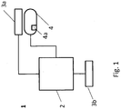
- Fig. 1 shows schematically an air conditioning system 1 according to an embodiment.
- the air conditioning system 1 comprises a unit 2, which provides air at the desired temperature, as well as the air outlets 3a and 3b.
- the air outlet 3a is located in the center console of a dashboard of a vehicle (not shown) and is connected to the unit 2 via air ducts (for example pipes).
- An air outlet 3b is arranged in the footwell of the passenger compartment and is also connected to the unit 2 via air ducts.
- the air conditioning system has an operating unit 4.
- the operating unit 4 is arranged below the air outlet 3a and also includes an electronic evaluation unit 4a, the operating inputs on the operating unit 4 evaluates and reports electronically to unit 2.
- the air conditioning system 2 is designed to carry out a temperature stratification within the framework of the specified target temperature, ie to adapt the respective temperature of the air actually determined by the unit 2 for the respective outlet 3a and 3b according to the inputs of the user on the operating unit 4.
- Fig. 2 shows schematically an operating unit 4 according to an embodiment.
- the operating unit 4 comprises a touch-sensitive strip 5 which is arranged behind a panel so that the user cannot see the strip 5 (in Fig. 2 indicated by a dashed illustration).
- the Sensitive strip 5 comprises individual sensor elements which are arranged below the LEDs 7a, but can detect touches in the area of the strip 5.
- the sensor elements are arranged between or around the LEDs; alternatively, the sensor elements are made of a transparent material and can then also overlay the LEDs.
- a first area 6a is optically displayed on the panel of the operating unit, for example by a border with a line. Furthermore, a second area 6b and a third area 6c are displayed optically, also for example by a border with a line.
- the closed shapes created for surfaces 6a, 6b and 6c can also be filled with a color, for example red or blue.
- a color change from the non-hatched area to the hatched area is also symbolized by hatching.
- LEDs 7a, 7b are also integrated in the operating unit as lighting elements. The LEDs 7a are typically not visible in the deactivated state when looking at the panel (in Fig. 2 indicated by a dashed border). An activated LED 7b is visible from the outside as a light spot, which is shown in FIG Fig. 2 is indicated by a filling.
- the status of the temperature stratification is indicated by the activated LED.
- a step from one LED to the next represents a temperature change of 1 ° C. of the air for the air outlet 3a and an opposite temperature change of 1 ° C. (or for example 0.7 ° C.) for the air outlet 3b.
- a step in the direction of the area 6b represents an increase in the air temperature by 1 ° C. for the air outlet 3a
- a step in the direction of the area 6c represents a temperature decrease of 1 ° C. for the air outlet 3a.
- An activated LED in the middle of the nine LEDs represents the status when no temperature stratification is carried out according to user inputs.
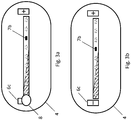
- FIGs 3a and 3b explain schematically the change in the temperature stratification in individual steps with the aid of the operating unit 4.
- the operating unit 4 uses the touch-sensitive strip to detect a touch 8 in the area 6c.
- the temperature previously provided for the respective air outlet is changed by 1 ° C.:
- the temperature of the air for the air outlet 3a is reduced by 1 ° C. and the air temperature for the air outlet 3b is increased by 1 ° C.
- the activation of the LEDs is changed.
- the previously active LED 7b in Fig. 3a is deactivated and the next LED in the direction of area 6c is activated, so that ultimately only LED 7b in Figure 3b is activated.
- the operator input can be repeated until the desired temperature stratification is reached.
- FIGs 4a and 4b schematically explain the change in the temperature stratification with the aid of the operating unit 4 by directly selecting the stratification.
- the user touches the point of the area 6a which corresponds to the desired temperature stratification.
- the area 6a is touched at the point 8.
- the temperature stratification is set according to the position of the contact in relation to the entire length of the area 6a.
- the user touches the second LED to the left as seen from the center position. This means that the temperature for the air outlet 3a is reduced by 2 ° C. compared to the temperature provided by the unit 2 for the air outlet 3a.
- the temperature for the air outlet 3b is increased by 2 ° C.
- the middle area around the middle LED can be marked separately.
Landscapes
- Physics & Mathematics (AREA)
- Thermal Sciences (AREA)
- Engineering & Computer Science (AREA)
- Mechanical Engineering (AREA)
- Air-Conditioning For Vehicles (AREA)
Description
- Die Erfindung betrifft eine Klimaanlage für den Innenraum eines Kraftfahrzeugs, sowie ein Verfahren zum Betreiben der Klimaanlage.
- Klimaanlagen für Kraftfahrzeuge, insbesondere PKW, sind wohlbekannt. Sie umfassen eine Einheit, die Luft mit der gewünschten Temperatur bereitstellt, sowie Luftführungen und Luftauslässe. Die Bedienung der Klimaanlage geschieht über Bedieneinheiten, die meist im Armaturenbrett des Kraftfahrzeugs angeordnet sind. Moderne Klimaanlagen erlauben die Einstellung einer Wunschtemperatur, deren Erreichung bzw. Einhaltung von der Klimaanlage mithilfe von Temperatursensoren überwacht wird und durch geeignete Wahl der Temperatur der ausströmenden Luft (Soll-Temperatur der ausströmenden Luft) sichergestellt wird. Die Bedienung der Klimaanlagen erfolgt meist über ein Bedienpanel, das über Drehknöpfe oder -regler verfügt, mit denen die Wunschtemperatur eingestellt wird.
- Meist verfügen derartige Klimaanlagen über mehrere Luftauslässe im Innenraum des Fahrzeugs, von denen einige im Fußraum und einige im oberen Bereich des Armaturenbretts auf Höhe des Lenkrads angeordnet sind. Weiterhin können Luftauslässe auch zu Defrost-Zwecken eingesetzt werden und dazu beispielsweise direkt auf Fahrzeugscheiben gerichtet sein. Um den Insassen eine möglichst passende Temperierung zu ermöglichen, bieten derzeitige Klimaanlage von einigen Fahrzeugen der BMW AG die Möglichkeit, über ein Rändel die Temperaturschichtung einzustellen. Ausgehend von der Wunschtemperatur und der durch die Klimaanlagen bestimmten Temperatur für die ausströmende Luft, wird dabei durch den Benutzer weiterhin die Temperaturdifferenz festgelegt, die zwischen der im Fußraum ausströmenden Luft und der auf Höhe des Lenkrads ausströmenden Luft besteht. So kann der Insasse des Fahrzeugs über das Rändel beispielsweise eine Temperaturschichtung einstellen, die eine höhere Ausströmtemperatur in Höhe des Lenkrads vorsieht, als im Fußraum. Alternativ kann durch das Rändel auch nur die Ausströmtemperatur in Höhe des Lenkrads verändert werden und die Ausströmtemperatur im Fußraum davon unbeeinflusst bleiben.
- Die Bedienung der Temperaturschichtung geschieht, wie bereits ausgeführt, über ein Rändel. Es ist die Aufgabe der hierin beschriebenen Erfindung, eine alternative Bedieneinheit zur Temperaturschichtung bereitzustellen.
- Dokument
EP1291205 offenbart eine bekannte Klimaanlage für den Innenraum eines Kraftfahrzeugs. Die Aufgabe wird durch die Gegenstände der unabhängigen Ansprüche gelöst. Vorteilhafte Weiterbildungen sind in den abhängigen Ansprüchen definiert. - Ein Aspekt der Erfindung betrifft eine Klimaanlage für den Innenraum eines Kraftfahrzeug, wobei die Klimaanlage eine Bedieneinheit umfasst; wobei die Klimaanlage mindestens zwei Luftauslässe umfasst; wobei die Bedieneinheit einen berührungssensitiven Streifen umfasst; wobei die Klimaanlage zu Folgendem eingerichtet ist: Getrenntes Steuern der Temperatur der Luft, die aus dem ersten Luftauslass strömt, und der Temperatur der Luft, die aus dem zweiten Luftauslass strömt; Bestimmen der Temperatur der Luft für den ersten bzw. zweiten Luftauslass unabhängig voneinander und abhängig von erfassten Berührungen des Streifens. Typischerweise ist einer der Luftauslässe im Fußraum der Fahrgastzelle angeordnet und einer im Armaturenbrett auf Höhe des Lenkrades; ebenso kann einer der Luftauslässe auch zu Defrost-Zwecken vorgesehen sein, mit andren Worten; derart ausgerichtet sein, dass die Luft direkt auf Fahrzeugscheiben strömt. Hierdurch kann eine Defrost-Luftschicht-Ebene gebildet werden. Die Klimaanlage kann weitere Luftauslässe umfassen, wobei die weiteren Luftauslässe ebenso wie einer der zwei Luftauslässe mit Luft versorgt werden. Die Berührungssensitivität des Streifens kann unter Verwendung von im Stand der Technik bekannter Technologien realisiert werden, beispielsweise mithilfe von Widerstandsveränderungen (resistiv), optischen Effekten oder kapazitiven Effekten.
- Hierin wird also vorgeschlagen das Bedienelement zur Temperaturschichtung als berührungssensitiven, also berührungsempfindlichen, Streifen auszuführen. Anstelle des Rändels wird somit dem Benutzer eine lineare Bedieneinheit zur Einstellung der Temperaturschichtung angeboten. Darüber hinaus erfolgt die Bedienung nicht über ein mechanisch bewegliches Element, sondern aufgrund einer erfassten Berührung. Die Ausgestaltung des Bedienelements als berührungssensitiver Streifen hat den Vorteil, dass die Lebensdauer des Bedienelements erhöht wird. Die Berührungssensitivität ermöglicht die Gestaltung der Bedieneinheit als geschlossene Fläche ohne Öffnungen, was die Reinigung erleichtert und eine Verschmutzung innerer Teile verhindert. Darüber hinaus wird die Bedienbarkeit der Vorrichtung auch nicht durch die mechanische Lebensdauer des Lagers oder des Drehmechanismus des Rändels und dessen Sensoren beeinträchtigt.
- Der Streifen muss keine gleichmäße Ausdehnung in Querrichtung aufweisen, sondern kann entlang der Längsrichtung unterschiedlich "dick" sein. Weiterhin kann der Streifen eine bogenförmige Gestalt haben oder in einem Spezialfall ein Kreissegment darstellen und damit zumindest annäherungsweise einen Drehsteller nachbilden. Die Längs- und Querrichtung beziehen sich dann auf den Verlauf des Streifens und folgen dem Bogen oder dem Kreissegment. Der Streifen kann in seiner Form einen Drehsteller nachbilden. Der berührungssensitive Streifen kann auch allgemein als berührungssensitiver Bereich bezeichnet werden.
- Der berührungssensitive Streifen kann aus einem Schichtaufbau bestehen, wobei die Berührung auf der obersten Schicht stattfindet. Typischerweise umfasst der Streifen zumindest eine Schicht zur Messung von Kapazitäten zwischen Elektroden und eine Schutzschicht. Darüber hinaus können auch Schichten vorgesehen sein, die der optisch ansprechenden Gestaltung dienen. Die oberste Schicht kann eine Ausdehnung und Gestalt aufweisen, die wesentlich größer ist, als die der Schicht zur Messung und insbesondere einen größeren, sichtbaren Teil eines Armaturenbretts bilden.
- Der berührungssensitive Streifen kann angrenzend und unterhalb von Luftauslässen angeordnet sein, aber auch in einem von den Luftauslässen abgetrennten Bedienelement der Klimaanlage.
- In einer vorteilhaften Ausgestaltung ist die Bedieneinheit zu Folgendem eingerichtet: In einem ersten Bereich: Erfassen der Position der Berührung des Streifens entlang einer Längsausdehnung des Streifens; wobei die Klimaanlage zu Folgendem eingerichtet ist: In Antwort auf das Erfassen einer Berührung im ersten Bereich des Streifens: Einstellen der Temperatur der Luft für den ersten und zweiten Luftauslass abhängig von der Position der Berührung entlang der Längsausdehnung des Streifens, wobei insbesondere die Temperatur des zweiten Luftauslassen auch unverändert bleiben kann. Hierin wird also eine Zuordnung der absoluten Position der Berührung bezogen auf die Längsausdehnung des Streifens und die Lufttemperatur vorgenommen. Dabei wird die Lufttemperatur für den ersten und den zweiten Luftauslass getrennt und unabhängig voneinander bestimmt. Es kann vorgesehen sein, dass die Temperatur für einen der Luftauslässe unverändert bleibt, während die Temperatur für den anderen Luftauslass geändert wird.
- Typischerweise ist die eingestellte Temperatur der Luft für den ersten Luftauslass gegenüber einer Soll-Temperatur höher, wenn die Berührung in einer ersten Hälfte der Längsausdehnung des Streifens erfasst wird; wobei die eingestellte Temperatur der Luft für den ersten Luftauslass gegenüber einer Soll-Temperatur niedriger ist, wenn die Berührung in der zweiten Hälfte der Längsausdehnung des Streifens erfasst wird. Jeder Position entlang der Längsausdehnung des Streifens kann eine absolute Abweichung oder eine relative Abweichung (ein Faktor) gegenüber einer Soll-Temperatur der aus dem ersten Auslass strömenden Luft zugewiesen sein. Beispielsweise kann einer Berührung an einer ¾ Position, also bei 75% der Länge der Ausdehnung (gemessen vom einem Ende des Streifens), eine Temperaturerhöhung um 2°C oder um den Faktor 1,1 für den ersten Luftauslass zugewiesen sein. Die Soll-Temperatur der Luft für einen Auslass ergibt sich aus der Regelung der Innenraumtemperatur durch die Klimaanalage gemäß der vorgegebenen Wunschtemperatur, unter der Annahme, dass keine Änderung der Standardluftschichtung vom Benutzer eingegeben wurde.
- In einer bevorzugten Implementierung ist die Bedieneinheit ferner zu Folgendem eingerichtet: Erfassen der Berührung eines zweiten Bereiches des Streifens, wobei der zweite Bereich an einem ersten Ende des Streifens angeordnet ist; Erfassen der Berührung eines dritten Bereiches des Streifens, wobei der dritte Bereich am zweiten Ende des Streifens angeordnet ist; wobei die Klimaanlage zu Folgendem eingerichtet ist: In Antwort auf das Erfassen einer Berührung im zweiten oder dritten Bereich des Streifens: Ändern der Temperatur der Luft für den ersten Luftauslass (ausgehend von der Soll-Temperatur) um einen dem jeweiligen Bereich zugewiesenen Wert oder Faktor und Ändern der Temperatur der Luft für den zweiten Luftauslass (ausgehend von der Soll-Temperatur) um einen anderen als den zugewiesenen Wert oder Faktor; wobei der dem zweiten Bereich zugewiesene Wert oder Faktor größer 0°C bzw. 1 ist und der dem dritten Bereich zugewiesene Wert oder Faktor kleiner 0°C bzw. 1 ist. Hierin wird also vorgeschlagen, dass bei Berührung der Enden des Streifens die Lufttemperatur ausgehend von der Soll-Lufttemperatur jeweils um einen Temperaturschritt erhöht oder erniedrigt wird. Dies wird manchmal auch als Toggeln bezeichnet. Der Temperaturschritt kann beispielsweise 1 °C sein. Dabei bezieht sich dieser Temperaturschritt auf die Lufttemperatur für den ersten Luftauslass. Die Temperatur für den zweiten Luftauslass ändert sich auf andere Weise, beispielsweise genau umgekehrt also z.B. -1°C oder auch auf andere Weise, z.B. - 1,5°C. Der zweite und dritte Bereich können jeweils von dem ersten Bereich abgesetzt sein. Es kann also ein Zwischenraum zwischen den jeweiligen Bereichen existieren, bei dessen Berührung keine Benutzereingabe erkannt wird.
- Der Streifen kann einzelne Sensorflächen im ersten Bereich umfassen, die entlang der Längsausdehnung des Streifens in einer Reihe und typischerweise gleichmäßig beabstandet angeordnet sind. Mithilfe der Sensorflächen (die unter einer Schutz- und ggf. Dekorschicht liegen) wird die Berührung des Streifens erkannt, wozu kapazitive Effekte ausgenutzt werden. Die Erkennung einer Berührung wird mithilfe einer elektronischen Auswerteeinheit vorgenommen, die Teil der Bedieneinheit der Klimaanlage ist. Der Streifen umfasst typischerweise auch Sensorflächen in dem zweiten und dritten Bereich, wobei diese nicht unbedingt in einer derselben Reihe und im selben Abstand wie die Sensorflächen des ersten Bereiches angeordnet sein müssen.
- Zusätzlich kann die Bedieneinheit weiterhin Leuchtelemente umfasst, die in einer Reihe angeordnet sind; und wobei die Klimaanlage ferner zu Folgendem eingerichtet ist: Aktivieren je eines oder mehrerer Leuchtelemente, derart, dass die Position des aktivierten bzw. der aktivierten Leuchtelemente in Bezug zur Längsausdehnung der Reihe die für den ersten Luftauslass bestimmte Lufttemperatur repräsentiert. Die Leuchtelemente sind typischerweise LEDs und können auch Lichtleiter umfassen. Hierin wird also vorgeschlagen, dem Benutzer eine optische Rückmeldung zu geben, welche Temperaturschichtung er gewählt hat. Diese Rückmeldung muss nicht unbedingt genaue Angaben zur Temperatur (in °C oder °F) machen, sondern kann auch rein relativ sein und nur die gerade gewählte Einstellung in Bezug auf den gesamt möglichen Einstellungsbereich. Dies wird durch die relative Positionierung des aktivierten Elements zur Gesamtausdehnung (in Längsrichtung) des Streifens erreicht.
- Die Reihe der Leuchtelemente kann sich mit dem berührungssensitiven Streifen zumindest teilweise in Längsausdehnung überlagern. Die optische Rückmeldung geschieht also an Stellen, an denen auch Eingaben gemacht werden können. Die Leuchtelemente sind typischerweise oberhalb und/oder neben der Sensoreinheit angeordnet damit man bei Berührung der Sensoreinheit die Leuchtelemente sehen kann.
- In einer Variante umfasst der erste Bereich zwei nicht verbundene Teilbereiche und die Bedieneinheit ist ferner zu Folgendem eingerichtet: Erfassen der Berührung des Streifens in einem vierten Bereich; wobei der vierte Bereich in Längsausdehnung zwischen den zwei Teilbereichen des ersten Bereiches angeordnet ist; wobei die Klimaanlage zu Folgendem eingerichtet ist: In Antwort auf das Erfassen einer Berührung im vierten Bereich des Streifens: Einstellen der Temperatur der Luft für den ersten und zweiten Luftauslass auf die jeweilige vorhergehend bestimmte Soll-Temperatur. Auf diese Weise wird ein Rücksetzen in den Standardzustand ermöglicht und eine eventuell eingestellte Schichtverteilung aufgehoben. Der separate vierte Bereich ist vorzugsweise mittig zwischen den Enden des Streifens angeordnet.
- In einem anderen Aspekt umfasst ein Kraftfahrzeug, insbesondere ein PKW, eine der vorstehend beschriebenen Klimaanlagen.
- In wieder einem anderen Aspekt umfasst ein Verfahren zum Steuern der Temperaturschichtung einer Klimaanlage für den Innenraum eines Kraftfahrzeug, wobei die Klimaanlage eine Bedieneinheit umfasst; wobei die Klimaanlage mindestens zwei Luftauslässe umfasst; Wobei die Bedieneinheit einen berührungssensitiven Streifen umfasst: Getrenntes Steuern der Temperatur der Luft, die aus dem ersten Luftauslass strömt, und der Temperatur der Luft, die aus dem zweiten Luftauslass strömt; Bestimmen der Temperatur der Luft für den ersten bzw. zweiten Luftauslass unabhängig voneinander und abhängig von erfassten Berührungen des Streifens. Das Verfahren kann durch die Schritte weitergebildet werden, die eine der oben beschriebenen Klimaanlagen ausführt.
-
-
Fig. 1 zeigt schematisch eine Klimaanlage gemäß einem Ausführungsbeispiel. -
Fig. 2 zeigt schematisch eine Bedieneinheit gemäß einem Ausführungsbeispiel. -
Fig. 3a, 3b ,4a und 4b erläutern schematisch die Funktion der Bedieneinheit gemäß Ausführungsbeispielen. - Gleiche Bezugszeichen beziehen sich auf sich entsprechende Elemente über die Figuren hinweg.
-
Fig. 1 zeigt schematisch eine Klimaanlage1 gemäß einem Ausführungsbeispiel. Die Klimaanlage 1 umfasst eine Einheit 2, die Luft mit der gewünschten Temperatur bereitstellt, sowie die Luftauslässe 3a und 3b. Der Luftauslass 3a befindet sich in der Mittelkonsole eines Armaturenbretts eines Fahrzeugs (nicht dargestellt) und ist über Luftführungen (beispielsweise Rohre) mit der Einheit 2 verbunden. Ein Luftauslass 3b ist im Fußraum der Fahrgastzelle angeordnet und ebenfalls über Luftführungen mit der Einheit 2 verbunden. Neben einem Bedienpanel (nicht dargestellt) zur Einstellung der Soll-Temperatur und weiterer Einstellmöglichkeiten der Klimaanlage, verfügt die Klimaanlage über eine Bedieneinheit 4. Die Bedieneinheit 4 ist unterhalb des Luftauslasses 3a angeordnet und umfasst auch eine elektronische Auswerteeinheit 4a, die Bedieneingaben an der Bedieneinheit 4 auswertet und an die Einheit 2 elektronisch berichtet. Die Klimaanlage 2 ist dazu ausgelegt im Rahmen der vorgegebenen Soll-Temperatur eine Temperatur-Schichtung vorzunehmen, d.h. die eigentlich von der Einheit 2 bestimmte jeweilige Temperatur der Luft für den jeweiligen Auslass 3a und 3b gemäß den Eingaben des Benutzers an der Bedieneinheit 4 anzupassen. -
Fig. 2 zeigt schematisch eine Bedieneinheit 4 gemäß einem Ausführungsbeispiel. Die Bedieneinheit 4 umfasst einen berührungsempfindlichen Streifen 5, der hinter einer Blende angeordnet ist, so dass der Benutzer den Streifen 5 nicht erkennen kann (inFig. 2 durch eine gestrichelte Darstellung angedeutet). Der empfindliche Streifen 5 umfasst einzelne Sensorelemente, die unterhalb der LEDs 7a angeordnet sind, aber im Bereich des Streifens 5 Berührungen erfassen können. In alternativen Ausführungsformen sind die Sensorelemente zwischen oder um die LEDs herum angeordnet; alternativ werden die Sensorelemente aus einem durchsichtigen Material gestaltet und können dann die LEDs auch überlagern. - Auf der Blende der Bedieneinheit wird ein erster Bereich 6a optisch angezeigt, beispielsweise durch eine Umrandung mit einer Linie. Ferner wird ein zweiter Bereich 6b und ein dritter Bereich 6c optisch angezeigt, ebenfalls beispielsweise durch eine Umrandung mit einer Linie. Die für Flächen 6a, 6b und 6c entstehenden geschlossenen Formen können auch mit einer Farbe ausgefüllt sein, beispielsweise rot oder blau. In dem Bereich 6a wird ferner durch eine Schraffierung ein Farbwechsel vom nicht-schraffierten Bereich zum schraffierten Bereich symbolisiert. Ebenfalls in der Bedieneinheit integriert sind LEDs 7a, 7b als Leuchtelemente. Die LEDs 7a sind im deaktivierten Zustand bei Betrachtung der Blende typischerweise nicht sichtbar (in
Fig. 2 angedeutet durch eine gestrichelte Umrandung). Eine aktivierte LED 7b ist von außen als Lichtfleck sichtbar, was inFig. 2 durch eine Ausfüllung angedeutet ist. - Im Betrieb wird durch die aktivierte LED der Zustand der Temperatur-Schichtung angezeigt. Vorliegend repräsentiert ein Schritt von einer LED zur nächsten eine Temperaturänderung von 1 °C der Luft für den Luftauslass 3a und eine entgegengesetzte Temperaturänderung um 1 °C (oder beispielsweise 0,7 °C) für den Luftauslass 3b. Ein Schritt in Richtung des Bereiches 6b repräsentiert eine Erhöhung der Lufttemperatur um 1 °C für den Luftauslass 3a, einem Schritt in Richtung des Bereiches 6c repräsentiert eine Temperaturerniedrigung um 1 °C für den Luftauslass 3a. Eine aktivierte LED in Mittelstellung der neun LEDs repräsentiert den Zustand, wenn keine Temperatur-Schichtung gemäß Benutzereingaben vorgenommen wird.
-
Fig. 3a und 3b erläutern schematisch die Änderung der Temperatur-Schichtung in Einzelschritten mithilfe Bedieneinheit 4. Im Betrieb erkennt mithilfe des berührungssensitiven Streifens die Bedieneinheit 4 eine Berührung 8 im Bereich 6c. In Antwort darauf wird die bisher für den jeweiligen Luftauslass vorgesehene Temperatur um 1 °C geändert: Die Temperatur der Luft für den Luftauslass 3a wird um 1 °C verringert und die Lufttemperatur für den Luftauslas 3b wird um 1 °C erhöht. Gleichzeitig wird die Aktivierung der LEDs verändert. Die bisher aktive LED 7b inFig. 3a wird deaktiviert und die nächste LED in Richtung des Bereiches 6c wird aktiviert, so dass schließlich nur die LED 7b inFig. 3b aktiviert ist. Die Bedieneingabe kann so lange wiederholt werden, bis die gewünschte Temperatur-Schichtung erreicht ist. -
Fig. 4a und 4b erläutern schematisch die Änderung der Temperatur-Schichtung mithilfe der Bedieneinheit 4 durch direkte Wahl der Schichtung. Im Betrieb berührt hierzu der Benutzer die Stelle des Bereiches 6a, die der gewünschten Temperatur-Schichtung entspricht. InFig. 4a wird der Bereich 6a an der Stelle 8 berührt. Entsprechend der Position der Berührung bezogen auf die ganze Längsausdehnung des Bereiches 6a, wird die Temperatur-Schichtung eingestellt. InFig. 4a berührt der Benutzer die zweite LED links von der Mittenposition aus gesehen. Dies bedeutet, dass die Temperatur für den Luftauslass 3a um 2 °C gegenüber der von der Einheit 2 vorgesehenen Temperatur für den Luftauslass 3a verringert wird. Gleichzeitig wird die Temperatur für den Luftauslass 3b um 2 °C erhöht. - Die Berührung des Bereiches 6a in dessen Mitte der Längsausdehnung führt zur Aufhebung der Temperatur-Schichtung. Der Mittenbereich um die mittlere LED herum kann gesondert gekennzeichnet werden.
Claims (10)
- Klimaanlage für den Innenraum eines Kraftfahrzeugs, wobei die Klimaanlage eine Bedieneinheit (4) umfasst; wobei die Klimaanlage mindestens zwei Luftauslässe (3a, 3b) umfasst;
Wobei die Bedieneinheit (4) einen berührungssensitiven Streifen (5) umfasst;
Wobei die Klimaanlage zu Folgendem eingerichtet ist:- Erfassen einer Berührung des Streifens (5);- Getrenntes Steuern der Temperatur der Luft, die aus dem ersten Luftauslass (3a) strömt, und der Temperatur der Luft, die aus dem zweiten Luftauslass (3b) strömt; dadurch gekennzeichnet, dass die Klimaanlage zu Folgendem eingerichtet ist:- Bestimmen der Temperatur der Luft für den ersten und zweiten Luftauslass (3a, 3b) unabhängig voneinander und abhängig von der erfassten Berührung des Streifens (5). - Klimaanlage nach Anspruch 1,
wobei die Bedieneinheit (4) zu Folgendem eingerichtet ist:- In einem ersten Bereich: Erfassen der Position der Berührung des Streifens (5) entlang einer Längsausdehnung des Streifens (5);wobei die Klimaanlage zu Folgendem eingerichtet ist:- In Antwort auf das Erfassen einer Berührung im ersten Bereich des Streifens (5): Einstellen der Temperatur der Luft für den ersten und auch den zweiten Luftauslass (3a, 3b) abhängig von der Position der Berührung entlang der Längsausdehnung des Streifens (5). - Klimaanlage nach Anspruch 2, wobei die eingestellte Temperatur der Luft für den ersten Luftauslass (3a) gegenüber einer Soll-Temperatur höher ist, wenn die Berührung in einer ersten Hälfte der Längsausdehnung des Streifens (5) erfasst wird; und wobei die eingestellte Temperatur der Luft für den ersten Luftauslass (3a) gegenüber einer Soll-Temperatur niedriger ist, wenn die Berührung in der zweiten Hälfte der Längsausdehnung des Streifens (5) erfasst wird.
- Klimaanlage nach einem der Ansprüche 2 oder 3,
wobei die Bedieneinheit (4) zu Folgendem eingerichtet ist:- Erfassen der Berührung eines zweiten Bereiches des Streifens (5), wobei der zweite Bereich an einem ersten Ende des Streifens (5) angeordnet ist;- Erfassen der Berührung eines dritten Bereiches des Streifens (5), wobei der dritte Bereich am zweiten Ende des Streifens (5) angeordnet ist;wobei die Klimaanlage zu Folgendem eingerichtet ist:- In Antwort auf das Erfassen einer Berührung im zweiten oder dritten Bereich des Streifens (5): Ändern der Temperatur der Luft für den ersten Luftauslass (3a) um einen dem jeweiligen Bereich zugewiesenen Wert oder Faktor und Ändern der Temperatur der Luft für den zweiten Luftauslass (3b) um einen anderen als den zugewiesenen Wert oder Faktor;- Wobei der dem zweiten Bereich zugewiesene Wert oder Faktor größer 0°C bzw. 1 ist und der dem dritten Bereich der zugewiesene Wert oder Faktor kleiner 0°C bzw. 1 ist. - Klimaanlage nach einem der Ansprüche 2 bis 4, wobei der Streifen (5) einzelne Sensorflächen im ersten Bereich umfasst, die entlang der Längsausdehnung des Streifens (5) in einer Reihe angeordnet sind.
- Klimaanlage nach einem der vorhergehenden Ansprüche wobei die Bedieneinheit (4) weiterhin Leuchtelemente umfasst, die in einer Reihe angeordnet sind;
wobei die Klimaanlage ferner zu Folgendem eingerichtet ist:- Aktivieren je eines oder mehrerer Leuchtelemente (7a, 7b), derart, dass die Position des aktivierten bzw. der aktivierten Leuchtelemente (7a, 7b) in Bezug zur Längsausdehnung der Reihe die für den ersten Luftauslass (3a) bestimmte Lufttemperatur repräsentiert. - Klimaanlage nach Anspruch 6, wobei die Reihe der Leuchtelemente (7a, 7b) sich mit dem berührungssensitiven Streifen (5) zumindest teilweise in Längsausdehnung überlagert.
- Klimaanlage nach einem der Ansprüche 2 bis 5, wobei der erste Bereich zwei nicht verbundene Teilbereiche umfasst;
wobei die Bedieneinheit (4) ferner zu Folgendem eingerichtet ist:Erfassen der Berührung des Streifens (5) in einem vierten Bereich; wobei der vierte Bereich in Längsausdehnung zwischen den zwei Teilbereichen des ersten Bereiches angeordnet ist;wobei die Klimaanlage zu Folgendem eingerichtet ist:
In Antwort auf das Erfassen einer Berührung im vierten Bereich des Streifens (5): Einstellen der Temperatur der Luft für den ersten und zweiten Luftauslass (3a, 3b) auf die jeweilige vorhergehend bestimmte Soll-Temperatur. - Kraftfahrzeug, umfassend eine Klimaanlage nach einem der vorhergehenden Ansprüche.
- Verfahren zum Steuern der Temperaturschichtung einer Klimaanlage für den Innenraum eines Kraftfahrzeug, wobei die Klimaanlage eine Bedieneinheit (4) umfasst; wobei die Klimaanlage mindestens zwei Luftauslässe (3a, 3b) umfasst; Wobei die Bedieneinheit (4) einen berührungssensitiven Streifen (5) umfasst; Wobei das Verfahren umfasst:- Erfassen einer Berührung des Streifens (5);- Getrenntes Steuern der Temperatur der Luft, die aus dem ersten Luftauslass (3a) strömt, und der Temperatur der Luft, die aus dem zweiten Luftauslass (3b) strömt;- Bestimmen der Temperatur der Luft für den ersten und zweiten Luftauslass (3a, 3b) unabhängig voneinander und abhängig von der erfassten Berührung des Streifens (5).
Applications Claiming Priority (2)
| Application Number | Priority Date | Filing Date | Title |
|---|---|---|---|
| DE102014207383.9A DE102014207383A1 (de) | 2014-04-17 | 2014-04-17 | Bedienung einer Klimaanlage für den Innenraum eines Kraftfahrzeugs |
| PCT/EP2015/057797 WO2015158614A1 (de) | 2014-04-17 | 2015-04-10 | Bedienung einer klimaanlage für den innenraum eines kraftfahrzeugs |
Publications (2)
| Publication Number | Publication Date |
|---|---|
| EP3131772A1 EP3131772A1 (de) | 2017-02-22 |
| EP3131772B1 true EP3131772B1 (de) | 2020-08-19 |
Family
ID=53015767
Family Applications (1)
| Application Number | Title | Priority Date | Filing Date |
|---|---|---|---|
| EP15719156.0A Active EP3131772B1 (de) | 2014-04-17 | 2015-04-10 | Bedienung einer klimaanlage für den innenraum eines kraftfahrzeugs |
Country Status (5)
| Country | Link |
|---|---|
| US (1) | US10434839B2 (de) |
| EP (1) | EP3131772B1 (de) |
| CN (1) | CN106163843B (de) |
| DE (1) | DE102014207383A1 (de) |
| WO (1) | WO2015158614A1 (de) |
Families Citing this family (6)
| Publication number | Priority date | Publication date | Assignee | Title |
|---|---|---|---|---|
| DE102017200947A1 (de) * | 2017-01-20 | 2018-07-26 | Audi Ag | Wärmeübertrager für ein Fahrzeug sowie ein Klimagerät und zugehöriges Verfahren |
| DE102018100939B4 (de) * | 2018-01-17 | 2026-03-26 | Dr. Ing. H.C. F. Porsche Aktiengesellschaft | Verfahren zum Betrieb eines Lufteinströmers |
| GB2582819B (en) | 2019-04-05 | 2024-01-03 | Dyson Technology Ltd | Vehicle vent assembly |
| GB2582818B (en) | 2019-04-05 | 2022-02-16 | Dyson Technology Ltd | Vehicle vent assembly |
| GB201904837D0 (en) | 2019-04-05 | 2019-05-22 | Dyson Technology Ltd | Vehicle vent assembly |
| DE102019127178A1 (de) * | 2019-10-09 | 2021-04-15 | Ford Global Technologies, Llc | Verfahren zum Betrieb einer Klimaanlage eines Kraftfahrzeugs |
Citations (2)
| Publication number | Priority date | Publication date | Assignee | Title |
|---|---|---|---|---|
| DE102008046625A1 (de) * | 2008-09-10 | 2010-04-29 | Behr-Hella Thermocontrol Gmbh | Bedieneinheit zur Einstellung der Temperatur und Luftverteilung in einem Fahrzeug |
| WO2013041946A1 (en) * | 2011-09-22 | 2013-03-28 | Toyota Jidosha Kabushiki Kaisha | Input apparatus and input apparatus processing method |
Family Cites Families (12)
| Publication number | Priority date | Publication date | Assignee | Title |
|---|---|---|---|---|
| DE60205437T2 (de) * | 2001-09-11 | 2006-05-24 | Trw Automotive Electronics & Components Gmbh & Co. Kg | Einstellungssystem einer Kraftfahrzeugklimaanlage |
| US6758265B2 (en) * | 2001-11-30 | 2004-07-06 | Visteon Global Technologies, Inc. | Temperature control strategy for a rear control system |
| US7180017B2 (en) * | 2003-12-22 | 2007-02-20 | Lear Corporation | Integrated center stack switch bank for motor vehicle |
| DE102004044355A1 (de) | 2004-09-09 | 2006-03-30 | E.G.O. Elektro-Gerätebau GmbH | Verfahren zur optischen Kennzeichnung eines Berührungsschalters und ein solcher Berührungsschalter |
| FR2931566B1 (fr) * | 2008-05-26 | 2010-04-30 | Continental Automotive France | Interface tactile pour chauffer ou climatiser un vehicule, et son procede de reglage |
| US8099209B2 (en) * | 2008-06-13 | 2012-01-17 | Visteon Global Technologies, Inc. | Multi-dimensional controls integration |
| DE102010010441A1 (de) * | 2010-02-25 | 2011-08-25 | Dr. Ing. h.c. F. Porsche Aktiengesellschaft, 70435 | Belüftungs- und Klimasystem eines Kraftfahrzeugs |
| DE102010010806B4 (de) * | 2010-03-09 | 2013-05-29 | Continental Automotive Gmbh | Bedienvorrichtung zur Eingabe von Steuerbefehlen in ein elektronisches Gerät |
| KR101669529B1 (ko) * | 2010-12-03 | 2016-10-26 | 한온시스템 주식회사 | 차량용 공조장치의 콘트롤러 |
| JP2013134546A (ja) * | 2011-12-26 | 2013-07-08 | Tokai Rika Co Ltd | 操作入力装置 |
| DE102013005027A1 (de) * | 2012-03-30 | 2013-10-02 | Marquardt Gmbh | Anzeigevorrichtung, insbesondere für ein Schaltelement |
| DE102012016109A1 (de) * | 2012-08-15 | 2014-02-20 | Volkswagen Aktiengesellschaft | Bedienvorrichtung zum Einstellen einer Klimatisierungsvorrichtung eines Fahrzeugs und Verfahren hierzu |
-
2014
- 2014-04-17 DE DE102014207383.9A patent/DE102014207383A1/de not_active Withdrawn
-
2015
- 2015-04-10 EP EP15719156.0A patent/EP3131772B1/de active Active
- 2015-04-10 WO PCT/EP2015/057797 patent/WO2015158614A1/de not_active Ceased
- 2015-04-10 CN CN201580019159.0A patent/CN106163843B/zh active Active
-
2016
- 2016-10-14 US US15/293,670 patent/US10434839B2/en active Active
Patent Citations (2)
| Publication number | Priority date | Publication date | Assignee | Title |
|---|---|---|---|---|
| DE102008046625A1 (de) * | 2008-09-10 | 2010-04-29 | Behr-Hella Thermocontrol Gmbh | Bedieneinheit zur Einstellung der Temperatur und Luftverteilung in einem Fahrzeug |
| WO2013041946A1 (en) * | 2011-09-22 | 2013-03-28 | Toyota Jidosha Kabushiki Kaisha | Input apparatus and input apparatus processing method |
Also Published As
| Publication number | Publication date |
|---|---|
| WO2015158614A1 (de) | 2015-10-22 |
| US10434839B2 (en) | 2019-10-08 |
| CN106163843B (zh) | 2018-11-27 |
| CN106163843A (zh) | 2016-11-23 |
| US20170028818A1 (en) | 2017-02-02 |
| EP3131772A1 (de) | 2017-02-22 |
| DE102014207383A1 (de) | 2015-10-22 |
Similar Documents
| Publication | Publication Date | Title |
|---|---|---|
| WO2015158614A1 (de) | Bedienung einer klimaanlage für den innenraum eines kraftfahrzeugs | |
| EP3630582B1 (de) | Fahrsystem zum automatisierten fahren mit mitteln zum markieren von bereichen am lenkrad und entsprechendes verfahren | |
| EP3411665B1 (de) | Kraftfahrzeug | |
| DE102015005126B3 (de) | Verfahren und Bedienungsvorrichtung zum Bedienen einer Klimaanlage eines Fahrzeugs | |
| DE102018118535A1 (de) | Einstellbare aerodynamische Anordnung und ein Verfahren | |
| DE102010018140B4 (de) | Temperatureinstellvorrichtung für ein Kraftfahrzeug | |
| DE102008035458A1 (de) | Bedienvorrichtung für mehrere Funktionen und Verfahren | |
| DE102008023405A1 (de) | Kraftfahrzeug mit einem Bedienfeld | |
| WO2008119424A1 (de) | Bedienelement für kraftfahrzeuge | |
| WO2018103984A1 (de) | Bedieneinrichtung für ein infotainmentsystem eines kraftfahrzeugs, verfahren zur ermittlung des aufenthaltsortes einer bedienperson eines solchen bedienelements | |
| DE102010022718A1 (de) | Verfahren und Vorrichtung zum unterstützten Parken eines Kraftfahrzeugs | |
| DE102004009308A1 (de) | Fahrerassistenzsystem | |
| DE102016221075A1 (de) | Ausströmer für eine Fahrzeugklimaanlage, Fahrzeug mit einer Fahrzeugklimaanlage, Verfahren, Vorrichtung und computerlesbares Speichermedium mit Instruktionen zum Anzeigen von Einstellgrössen einer Fahrzeugklimaanlage | |
| WO2016016050A1 (de) | Verfahren zum bedienen einer lichtfunktion von kraftfahrzeugscheinwerfern und kraftfahrzeug mit einer anzeigeeinrichtung und einem bedienelement für eine bedienung der lichtfunktion der kraftfahrzeugscheinwerfer | |
| DE112014006474T5 (de) | Betätigungsvorrichtung | |
| DE112019002726T5 (de) | Steuersystem für ein Fahrzeug | |
| WO2020144016A1 (de) | Bedienvorrichtung zur bedienung mindestens eines gerätes und verfahren zur bedienung einer solchen bedienvorrichtung | |
| DE102016207611B4 (de) | Anzeige- und Bediensystem | |
| DE102014019159A1 (de) | Bedienvorrichtung für ein Kraftfahrzeug mit einer sensorischen Oberfläche und einem Führungselement | |
| EP3263399B1 (de) | Verfahren und vorrichtung zum steuern der klimatisierung eines fahrzeugsitzes | |
| EP3102453B1 (de) | Verfahren und vorrichtung zum anzeigen einer veränderung einer einstellung zumindest eines parameters einer fahrzeugfunktion | |
| DE102024111558A1 (de) | Sensoranordnung für ein Lenkrad eines Fahrzeugs und Verfahren zum Betreiben einer Sensoranordnung | |
| DE20318673U1 (de) | Vorrichtung zur Geschwindigkeitskontrolle eines Kraftfahrzeugs | |
| DE102019127178A1 (de) | Verfahren zum Betrieb einer Klimaanlage eines Kraftfahrzeugs | |
| DE102014213024A1 (de) | Bedieneinrichtung für ein Kraftfahrzeug, Bediensystem sowie Verfahren zum Betreiben einer Bedieneinrichtung |
Legal Events
| Date | Code | Title | Description |
|---|---|---|---|
| STAA | Information on the status of an ep patent application or granted ep patent |
Free format text: STATUS: THE INTERNATIONAL PUBLICATION HAS BEEN MADE |
|
| PUAI | Public reference made under article 153(3) epc to a published international application that has entered the european phase |
Free format text: ORIGINAL CODE: 0009012 |
|
| STAA | Information on the status of an ep patent application or granted ep patent |
Free format text: STATUS: REQUEST FOR EXAMINATION WAS MADE |
|
| 17P | Request for examination filed |
Effective date: 20161010 |
|
| AK | Designated contracting states |
Kind code of ref document: A1 Designated state(s): AL AT BE BG CH CY CZ DE DK EE ES FI FR GB GR HR HU IE IS IT LI LT LU LV MC MK MT NL NO PL PT RO RS SE SI SK SM TR |
|
| AX | Request for extension of the european patent |
Extension state: BA ME |
|
| DAV | Request for validation of the european patent (deleted) | ||
| DAX | Request for extension of the european patent (deleted) | ||
| STAA | Information on the status of an ep patent application or granted ep patent |
Free format text: STATUS: EXAMINATION IS IN PROGRESS |
|
| 17Q | First examination report despatched |
Effective date: 20181220 |
|
| GRAP | Despatch of communication of intention to grant a patent |
Free format text: ORIGINAL CODE: EPIDOSNIGR1 |
|
| STAA | Information on the status of an ep patent application or granted ep patent |
Free format text: STATUS: GRANT OF PATENT IS INTENDED |
|
| INTG | Intention to grant announced |
Effective date: 20200430 |
|
| GRAS | Grant fee paid |
Free format text: ORIGINAL CODE: EPIDOSNIGR3 |
|
| GRAA | (expected) grant |
Free format text: ORIGINAL CODE: 0009210 |
|
| STAA | Information on the status of an ep patent application or granted ep patent |
Free format text: STATUS: THE PATENT HAS BEEN GRANTED |
|
| AK | Designated contracting states |
Kind code of ref document: B1 Designated state(s): AL AT BE BG CH CY CZ DE DK EE ES FI FR GB GR HR HU IE IS IT LI LT LU LV MC MK MT NL NO PL PT RO RS SE SI SK SM TR |
|
| REG | Reference to a national code |
Ref country code: CH Ref legal event code: EP |
|
| REG | Reference to a national code |
Ref country code: DE Ref legal event code: R096 Ref document number: 502015013275 Country of ref document: DE |
|
| REG | Reference to a national code |
Ref country code: AT Ref legal event code: REF Ref document number: 1303537 Country of ref document: AT Kind code of ref document: T Effective date: 20200915 |
|
| REG | Reference to a national code |
Ref country code: IE Ref legal event code: FG4D Free format text: LANGUAGE OF EP DOCUMENT: GERMAN |
|
| REG | Reference to a national code |
Ref country code: LT Ref legal event code: MG4D |
|
| REG | Reference to a national code |
Ref country code: NL Ref legal event code: MP Effective date: 20200819 |
|
| PG25 | Lapsed in a contracting state [announced via postgrant information from national office to epo] |
Ref country code: HR Free format text: LAPSE BECAUSE OF FAILURE TO SUBMIT A TRANSLATION OF THE DESCRIPTION OR TO PAY THE FEE WITHIN THE PRESCRIBED TIME-LIMIT Effective date: 20200819 Ref country code: LT Free format text: LAPSE BECAUSE OF FAILURE TO SUBMIT A TRANSLATION OF THE DESCRIPTION OR TO PAY THE FEE WITHIN THE PRESCRIBED TIME-LIMIT Effective date: 20200819 Ref country code: GR Free format text: LAPSE BECAUSE OF FAILURE TO SUBMIT A TRANSLATION OF THE DESCRIPTION OR TO PAY THE FEE WITHIN THE PRESCRIBED TIME-LIMIT Effective date: 20201120 Ref country code: PT Free format text: LAPSE BECAUSE OF FAILURE TO SUBMIT A TRANSLATION OF THE DESCRIPTION OR TO PAY THE FEE WITHIN THE PRESCRIBED TIME-LIMIT Effective date: 20201221 Ref country code: BG Free format text: LAPSE BECAUSE OF FAILURE TO SUBMIT A TRANSLATION OF THE DESCRIPTION OR TO PAY THE FEE WITHIN THE PRESCRIBED TIME-LIMIT Effective date: 20201119 Ref country code: NO Free format text: LAPSE BECAUSE OF FAILURE TO SUBMIT A TRANSLATION OF THE DESCRIPTION OR TO PAY THE FEE WITHIN THE PRESCRIBED TIME-LIMIT Effective date: 20201119 Ref country code: FI Free format text: LAPSE BECAUSE OF FAILURE TO SUBMIT A TRANSLATION OF THE DESCRIPTION OR TO PAY THE FEE WITHIN THE PRESCRIBED TIME-LIMIT Effective date: 20200819 Ref country code: SE Free format text: LAPSE BECAUSE OF FAILURE TO SUBMIT A TRANSLATION OF THE DESCRIPTION OR TO PAY THE FEE WITHIN THE PRESCRIBED TIME-LIMIT Effective date: 20200819 |
|
| PG25 | Lapsed in a contracting state [announced via postgrant information from national office to epo] |
Ref country code: PL Free format text: LAPSE BECAUSE OF FAILURE TO SUBMIT A TRANSLATION OF THE DESCRIPTION OR TO PAY THE FEE WITHIN THE PRESCRIBED TIME-LIMIT Effective date: 20200819 Ref country code: RS Free format text: LAPSE BECAUSE OF FAILURE TO SUBMIT A TRANSLATION OF THE DESCRIPTION OR TO PAY THE FEE WITHIN THE PRESCRIBED TIME-LIMIT Effective date: 20200819 Ref country code: LV Free format text: LAPSE BECAUSE OF FAILURE TO SUBMIT A TRANSLATION OF THE DESCRIPTION OR TO PAY THE FEE WITHIN THE PRESCRIBED TIME-LIMIT Effective date: 20200819 Ref country code: NL Free format text: LAPSE BECAUSE OF FAILURE TO SUBMIT A TRANSLATION OF THE DESCRIPTION OR TO PAY THE FEE WITHIN THE PRESCRIBED TIME-LIMIT Effective date: 20200819 Ref country code: IS Free format text: LAPSE BECAUSE OF FAILURE TO SUBMIT A TRANSLATION OF THE DESCRIPTION OR TO PAY THE FEE WITHIN THE PRESCRIBED TIME-LIMIT Effective date: 20201219 |
|
| PG25 | Lapsed in a contracting state [announced via postgrant information from national office to epo] |
Ref country code: DK Free format text: LAPSE BECAUSE OF FAILURE TO SUBMIT A TRANSLATION OF THE DESCRIPTION OR TO PAY THE FEE WITHIN THE PRESCRIBED TIME-LIMIT Effective date: 20200819 Ref country code: CZ Free format text: LAPSE BECAUSE OF FAILURE TO SUBMIT A TRANSLATION OF THE DESCRIPTION OR TO PAY THE FEE WITHIN THE PRESCRIBED TIME-LIMIT Effective date: 20200819 Ref country code: EE Free format text: LAPSE BECAUSE OF FAILURE TO SUBMIT A TRANSLATION OF THE DESCRIPTION OR TO PAY THE FEE WITHIN THE PRESCRIBED TIME-LIMIT Effective date: 20200819 Ref country code: SM Free format text: LAPSE BECAUSE OF FAILURE TO SUBMIT A TRANSLATION OF THE DESCRIPTION OR TO PAY THE FEE WITHIN THE PRESCRIBED TIME-LIMIT Effective date: 20200819 Ref country code: RO Free format text: LAPSE BECAUSE OF FAILURE TO SUBMIT A TRANSLATION OF THE DESCRIPTION OR TO PAY THE FEE WITHIN THE PRESCRIBED TIME-LIMIT Effective date: 20200819 |
|
| REG | Reference to a national code |
Ref country code: DE Ref legal event code: R097 Ref document number: 502015013275 Country of ref document: DE |
|
| PG25 | Lapsed in a contracting state [announced via postgrant information from national office to epo] |
Ref country code: AL Free format text: LAPSE BECAUSE OF FAILURE TO SUBMIT A TRANSLATION OF THE DESCRIPTION OR TO PAY THE FEE WITHIN THE PRESCRIBED TIME-LIMIT Effective date: 20200819 Ref country code: ES Free format text: LAPSE BECAUSE OF FAILURE TO SUBMIT A TRANSLATION OF THE DESCRIPTION OR TO PAY THE FEE WITHIN THE PRESCRIBED TIME-LIMIT Effective date: 20200819 |
|
| PLBE | No opposition filed within time limit |
Free format text: ORIGINAL CODE: 0009261 |
|
| STAA | Information on the status of an ep patent application or granted ep patent |
Free format text: STATUS: NO OPPOSITION FILED WITHIN TIME LIMIT |
|
| PG25 | Lapsed in a contracting state [announced via postgrant information from national office to epo] |
Ref country code: SK Free format text: LAPSE BECAUSE OF FAILURE TO SUBMIT A TRANSLATION OF THE DESCRIPTION OR TO PAY THE FEE WITHIN THE PRESCRIBED TIME-LIMIT Effective date: 20200819 |
|
| 26N | No opposition filed |
Effective date: 20210520 |
|
| PG25 | Lapsed in a contracting state [announced via postgrant information from national office to epo] |
Ref country code: SI Free format text: LAPSE BECAUSE OF FAILURE TO SUBMIT A TRANSLATION OF THE DESCRIPTION OR TO PAY THE FEE WITHIN THE PRESCRIBED TIME-LIMIT Effective date: 20200819 |
|
| PG25 | Lapsed in a contracting state [announced via postgrant information from national office to epo] |
Ref country code: MC Free format text: LAPSE BECAUSE OF FAILURE TO SUBMIT A TRANSLATION OF THE DESCRIPTION OR TO PAY THE FEE WITHIN THE PRESCRIBED TIME-LIMIT Effective date: 20200819 |
|
| PG25 | Lapsed in a contracting state [announced via postgrant information from national office to epo] |
Ref country code: LU Free format text: LAPSE BECAUSE OF NON-PAYMENT OF DUE FEES Effective date: 20210410 |
|
| REG | Reference to a national code |
Ref country code: BE Ref legal event code: MM Effective date: 20210430 |
|
| PG25 | Lapsed in a contracting state [announced via postgrant information from national office to epo] |
Ref country code: CH Free format text: LAPSE BECAUSE OF NON-PAYMENT OF DUE FEES Effective date: 20210430 Ref country code: LI Free format text: LAPSE BECAUSE OF NON-PAYMENT OF DUE FEES Effective date: 20210430 |
|
| PG25 | Lapsed in a contracting state [announced via postgrant information from national office to epo] |
Ref country code: IE Free format text: LAPSE BECAUSE OF NON-PAYMENT OF DUE FEES Effective date: 20210410 |
|
| PG25 | Lapsed in a contracting state [announced via postgrant information from national office to epo] |
Ref country code: IS Free format text: LAPSE BECAUSE OF FAILURE TO SUBMIT A TRANSLATION OF THE DESCRIPTION OR TO PAY THE FEE WITHIN THE PRESCRIBED TIME-LIMIT Effective date: 20201219 |
|
| REG | Reference to a national code |
Ref country code: AT Ref legal event code: MM01 Ref document number: 1303537 Country of ref document: AT Kind code of ref document: T Effective date: 20210410 |
|
| PG25 | Lapsed in a contracting state [announced via postgrant information from national office to epo] |
Ref country code: BE Free format text: LAPSE BECAUSE OF NON-PAYMENT OF DUE FEES Effective date: 20210430 |
|
| PG25 | Lapsed in a contracting state [announced via postgrant information from national office to epo] |
Ref country code: AT Free format text: LAPSE BECAUSE OF NON-PAYMENT OF DUE FEES Effective date: 20210410 |
|
| PG25 | Lapsed in a contracting state [announced via postgrant information from national office to epo] |
Ref country code: HU Free format text: LAPSE BECAUSE OF FAILURE TO SUBMIT A TRANSLATION OF THE DESCRIPTION OR TO PAY THE FEE WITHIN THE PRESCRIBED TIME-LIMIT; INVALID AB INITIO Effective date: 20150410 |
|
| P01 | Opt-out of the competence of the unified patent court (upc) registered |
Effective date: 20230503 |
|
| PG25 | Lapsed in a contracting state [announced via postgrant information from national office to epo] |
Ref country code: CY Free format text: LAPSE BECAUSE OF FAILURE TO SUBMIT A TRANSLATION OF THE DESCRIPTION OR TO PAY THE FEE WITHIN THE PRESCRIBED TIME-LIMIT Effective date: 20200819 |
|
| PG25 | Lapsed in a contracting state [announced via postgrant information from national office to epo] |
Ref country code: MK Free format text: LAPSE BECAUSE OF FAILURE TO SUBMIT A TRANSLATION OF THE DESCRIPTION OR TO PAY THE FEE WITHIN THE PRESCRIBED TIME-LIMIT Effective date: 20200819 |
|
| PG25 | Lapsed in a contracting state [announced via postgrant information from national office to epo] |
Ref country code: TR Free format text: LAPSE BECAUSE OF FAILURE TO SUBMIT A TRANSLATION OF THE DESCRIPTION OR TO PAY THE FEE WITHIN THE PRESCRIBED TIME-LIMIT Effective date: 20200819 |
|
| PG25 | Lapsed in a contracting state [announced via postgrant information from national office to epo] |
Ref country code: MT Free format text: LAPSE BECAUSE OF FAILURE TO SUBMIT A TRANSLATION OF THE DESCRIPTION OR TO PAY THE FEE WITHIN THE PRESCRIBED TIME-LIMIT Effective date: 20200819 |
|
| PGFP | Annual fee paid to national office [announced via postgrant information from national office to epo] |
Ref country code: DE Payment date: 20250408 Year of fee payment: 11 |
|
| PGFP | Annual fee paid to national office [announced via postgrant information from national office to epo] |
Ref country code: IT Payment date: 20250430 Year of fee payment: 11 |
|
| PGFP | Annual fee paid to national office [announced via postgrant information from national office to epo] |
Ref country code: FR Payment date: 20250422 Year of fee payment: 11 |
|
| PGFP | Annual fee paid to national office [announced via postgrant information from national office to epo] |
Ref country code: GB Payment date: 20260324 Year of fee payment: 12 |