EP3131718B1 - Machine for cutting cardboard tubes - Google Patents
Machine for cutting cardboard tubes Download PDFInfo
- Publication number
- EP3131718B1 EP3131718B1 EP15714665.5A EP15714665A EP3131718B1 EP 3131718 B1 EP3131718 B1 EP 3131718B1 EP 15714665 A EP15714665 A EP 15714665A EP 3131718 B1 EP3131718 B1 EP 3131718B1
- Authority
- EP
- European Patent Office
- Prior art keywords
- tube
- blade
- machine according
- carriage
- cutting
- Prior art date
- Legal status (The legal status is an assumption and is not a legal conclusion. Google has not performed a legal analysis and makes no representation as to the accuracy of the status listed.)
- Active
Links
Images


Classifications
-
- B—PERFORMING OPERATIONS; TRANSPORTING
- B26—HAND CUTTING TOOLS; CUTTING; SEVERING
- B26D—CUTTING; DETAILS COMMON TO MACHINES FOR PERFORATING, PUNCHING, CUTTING-OUT, STAMPING-OUT OR SEVERING
- B26D1/00—Cutting through work characterised by the nature or movement of the cutting member or particular materials not otherwise provided for; Apparatus or machines therefor; Cutting members therefor
- B26D1/56—Cutting through work characterised by the nature or movement of the cutting member or particular materials not otherwise provided for; Apparatus or machines therefor; Cutting members therefor involving a cutting member which travels with the work otherwise than in the direction of the cut, i.e. flying cutter
- B26D1/60—Cutting through work characterised by the nature or movement of the cutting member or particular materials not otherwise provided for; Apparatus or machines therefor; Cutting members therefor involving a cutting member which travels with the work otherwise than in the direction of the cut, i.e. flying cutter and is mounted on a movable carriage
-
- B—PERFORMING OPERATIONS; TRANSPORTING
- B26—HAND CUTTING TOOLS; CUTTING; SEVERING
- B26D—CUTTING; DETAILS COMMON TO MACHINES FOR PERFORATING, PUNCHING, CUTTING-OUT, STAMPING-OUT OR SEVERING
- B26D3/00—Cutting work characterised by the nature of the cut made; Apparatus therefor
- B26D3/16—Cutting rods or tubes transversely
-
- B—PERFORMING OPERATIONS; TRANSPORTING
- B26—HAND CUTTING TOOLS; CUTTING; SEVERING
- B26D—CUTTING; DETAILS COMMON TO MACHINES FOR PERFORATING, PUNCHING, CUTTING-OUT, STAMPING-OUT OR SEVERING
- B26D5/00—Arrangements for operating and controlling machines or devices for cutting, cutting-out, stamping-out, punching, perforating, or severing by means other than cutting
- B26D5/20—Arrangements for operating and controlling machines or devices for cutting, cutting-out, stamping-out, punching, perforating, or severing by means other than cutting with interrelated action between the cutting member and work feed
- B26D5/22—Arrangements for operating and controlling machines or devices for cutting, cutting-out, stamping-out, punching, perforating, or severing by means other than cutting with interrelated action between the cutting member and work feed having the cutting member and work feed mechanically connected
-
- B—PERFORMING OPERATIONS; TRANSPORTING
- B26—HAND CUTTING TOOLS; CUTTING; SEVERING
- B26D—CUTTING; DETAILS COMMON TO MACHINES FOR PERFORATING, PUNCHING, CUTTING-OUT, STAMPING-OUT OR SEVERING
- B26D7/00—Details of apparatus for cutting, cutting-out, stamping-out, punching, perforating, or severing by means other than cutting
- B26D7/06—Arrangements for feeding or delivering work of other than sheet, web, or filamentary form
- B26D7/0683—Arrangements for feeding or delivering work of other than sheet, web, or filamentary form specially adapted for elongated articles
Definitions
- the present invention relates to a machine for cutting cardboard tubes, in particular for manufacturing paper rolls or "logs".
- the tube-forming machines are used to produce the cardboard tube (also known as "core") on which the paper is wound to form a roll or "log" that, at a later stage, is divided in a plurality of elements having a given length to obtain toilet paper rolls, kitchen paper rolls etc.
- the tube is made of cardboard strips that are unwound from corresponding reels and are wound onto a horizontal metal spindle and glued to each other thus forming a self-supporting tubular body.
- two or three cardboard strips are used, depending on the thickness of the cardboard core to be manufactured.
- the cardboard strips are partially superimposed on each other and, by means of a eight-shaped belt wound on two driving rollers, they are rolled around the spindle and pushed forward to obtain the tubular cardboard tube that advances along the same spindle. Said belt is also wound around the spindle so as to engage the incoming cardboard strips and produce the effect described above.
- a cutting unit is used to cut the tubular cardboard tube to a predetermined length corresponding to the length of the logs to be produced by means of other machines called "rewinders".
- the conventional cutting units provide concurrent execution of three movements: bi-directional movement of a blade supporting carriage parallel to the tube subjected to cutting, rotary motion of the blade about its own axis, and vertical movement of the blade during the cutting step. This implies drawbacks due to the constructive complexity, the weight and maintenance requirements of such cutting units.
- the main purpose of the present invention is to simplify the construction of the cutting units destined to cut cardboard tubes, in particular tubes used for the production of paper rolls or "logs".
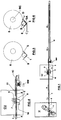
- a cutting machine or cutting unit (CU) in accordance with the present invention is positioned downstream of a tube-forming machine (TF) which produces the tube (1) by means of helical winding of one or more strips of cardboard on a spindle (2) with the aid of a belt winder (3).
- TF tube-forming machine
- the operation and the structure of the tube-forming machine (TF) are known to those skilled in the art and, therefore, are not described in greater detail.
- a tube-forming machine of this type is described, for example, in WO 95/10400 and WO 95/10399 .
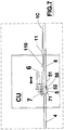
- the tube (1) that gradually forms on the mandrel (2) moves on a fixed horizontal guide (4) having a transverse profile in the shape of "V” with the concavity facing upwards. While advances (arrow “A"), the tube (1) is also subject to rotation about its longitudinal axis (x). Said guide (4) extends up to the cutting unit (CU) where, downstream of the guide (4), is arranged another guide (5) which, as further described in the following, is connected to a device which controls its vertical movement.
- the second guide (5) is also horizontal and has a transverse profile in the shape of "V” with the concavity facing upwards. Furthermore, the second guide (5) is in correspondence of the cutting unit (CU), that is in a position below a circular blade (6) through which the tube (1) is cut.
- Said blade (6) is mounted on a carriage (7) which allows to move it parallel to the guides (4) and (5), i.e. parallel to the tube (1) to be cut. Moreover, the blade (6) is oriented orthogonally to the guides (4) and (5). In other words, the cutting plane of the blade (6) is transverse relative to the tube (1).
- a third guide (8) Downstream of the second guide (5) there is a third guide (8) which, as the first guide (4), is fixed.
- the third guide (8) is also horizontal, providing an ideal extension of the first guide (4).
- the said first, second and third guides (4, 5, 8) act as a support for the tube (1).
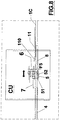
- the second guide (5) is associated with a device which controls its vertical movement.
- Said device in the example shown in the drawings, comprises a linear actuator (9) connected by two parallel levers (10) to the lower surface of the guide (5).
- the levers (10) Through the levers (10), the run to the right or to the left of the actuator (9) implies the corresponding lifting or lowering of the guide (5). It is understood, however, that the vertical movement of the second guide (5) can be obtained in any other way.
- the third guide (8) may possibly be arranged another guide (11) with a mouth (110) oriented towards the cutting unit (CU).
- the inherent flexibility of the tube (1) allows to push up its part lying on the second guide (5) without the need to retain even the parts that lie on the first and third guide.
- the carriage (7) must only support the blade (6) with the associated motor (not visible in the drawings) and needs not to approach the blade (6) to the tube (1) since the second guide (5) pushes the latter towards the blade (6).
- the guides (4), (5), and (8) form, on the whole, a cradle or a support in which the tube (1) can slide, with a part (in the example, the second guide 5) that can be moved by and towards the blade (6) to obtain the corresponding movement of the tube (1) in order to move it towards the blade (6) during execution of the cut and to keep it spaced from the blade (6) during the tube formation (1).
- the reference "W” indicates a belt conveyor driven by a corresponding motor (MW), placed downstream of the cutting unit (CU), to remove the portions (1C) formed by the cutting of the tube (1).
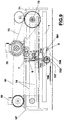
- the second guide (5) is secured to the carriage (7), that is hinged at its rear (the side facing the tube-forming machine TF) to a lower appendage (70) of the carriage (7) by a pin (71) with horizontal axis. More particularly, the axis of the pin (71) is orthogonal to the aforementioned direction "A". In this way, the second guide (5), being free to oscillate around the axis of the pin (71), can rotate as further described in the following.
- the second guide of the example of Fig.7 and Fig.8 is provided with a roller (50) adapted to slide on a cam (51) placed in a fixed position between the fixed guides (4, 8) under the blade (6).
- the second guide of the example of Fig.7 and Fig.8 is provided with a wheel (52) in an intermediate position between the pin (71) and the roller (50).
- the presence of the wheel (52) reduces the friction with the tube (1) that during the cut moves forward and rotates on its longitudinal axis.
- the guide (5) In Fig.7 the guide (5) is in the lowered position, whereas in Fig.8 the same guide (5) is raised.
- the cam (51) is raised and lowered, as indicated by the arrow "F5", to place the same cam in position of lifting of the second guide (5) and respectively in position of lowering of the latter.
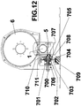
- the said movement mechanism for the second guide (5) comprises a pin (700) protruding from a lower edge of a side of the carriage (7), on which pin (700) is fitted a coaxial bush (706) and the latter is mounted on a pressure plate (701) with the corresponding compression spring (702) coaxial and external to the pin (700) and the bushing (706).
- the pin (700) is oriented transversely to said side of the carriage (7), that is parallel to the axis of the motor (70) that moves the carriage (7), and has a tail or root portion inserted in said sidewall and an opposite free end facing the plane of the blade (6) so as to be oriented perpendicular to the second guide (5).
- a wheel (703) On the bushing (706) there is fitted a wheel (703) which is pushed from behind by the pressure plate (701).
- the pressure plate (701) exerts on the wheel (703) a direct thrust towards the free end of the pin (700).
- the wheel (703) is arranged so as to have a first face turned towards the cup (701) and a second face turned towards the free end of the pin (700).
- On the second face of the wheel (703) is applied a friction disc (704).
- a cylindrical pad (705) is fitted near the free end of the bushing (706).
- the friction disc (704) is positioned between the second face of the wheel (703) and the pad (705).
- the pad (705) has a transverse eccentric pin (707) which projects axially from the face opposite to that facing the friction disc (704).
- the pad (705) also features a radial pin (710) intended to abut, as further described in the following, with a fixed element (711) located above the same pad (705).
- Said transverse eccentric pin (707) is inserted in a side (the left side 708 in Fig.11 ) of the second guide (5) which consists of a box-like structure open at the top, with a right side and a left side and a lower base constituted by a movable plate (500), and wherein the two sides are connected to a lower rear appendage of the carriage (7) by means of a transverse horizontal pin (501). Therefore, the guide (5) moves with the carriage (7) parallel to the tube (1) to be cut and can rotate around the axis of the pin (501) so as to be able to lift the tube (1) towards the blade (6) as further described in the following.
- the contact between the segment (709) of friction material and the wheel (701), while the carriage (7) moves, causes the rotation of the latter and, consequently, determines the rotation of the pad (705) which transmits this rotation to the guide (5), via the pin (707), until the radial pin (710) abuts on the overlying fixed element (711).
- the cutting unit is arranged to push the tube (1) to be cut towards the blade (6).
- the movable part (5) of the element (4, 5, 8) that supports the tube (1) is mechanically independent of the carriage (7).
- the said mobile part (5) is mechanically secured to the carriage (7), in such a way that the movement of the latter involves the movement of the mobile part (5).
- the blade is vertical. Furthermore, preferably, the blade executes the cut by removing material from the tube (1).
- the blade is serrated as shown schematically in Fig.11 .
Landscapes
- Life Sciences & Earth Sciences (AREA)
- Forests & Forestry (AREA)
- Engineering & Computer Science (AREA)
- Mechanical Engineering (AREA)
- Making Paper Articles (AREA)
- Nonmetal Cutting Devices (AREA)
- Shearing Machines (AREA)
- Details Of Cutting Devices (AREA)
Priority Applications (2)
| Application Number | Priority Date | Filing Date | Title |
|---|---|---|---|
| RS20180249A RS56918B1 (sr) | 2014-04-17 | 2015-01-28 | Uređaj za rezanje kartonskih cevi |
| PL15714665T PL3131718T3 (pl) | 2014-04-17 | 2015-01-28 | Maszyna do cięcia kartonowych rurek |
Applications Claiming Priority (2)
| Application Number | Priority Date | Filing Date | Title |
|---|---|---|---|
| ITFI20140088 | 2014-04-17 | ||
| PCT/IT2015/000014 WO2015159311A1 (en) | 2014-04-17 | 2015-01-28 | Machine for cutting cardboard tubes |
Publications (2)
| Publication Number | Publication Date |
|---|---|
| EP3131718A1 EP3131718A1 (en) | 2017-02-22 |
| EP3131718B1 true EP3131718B1 (en) | 2018-01-24 |
Family
ID=51033305
Family Applications (1)
| Application Number | Title | Priority Date | Filing Date |
|---|---|---|---|
| EP15714665.5A Active EP3131718B1 (en) | 2014-04-17 | 2015-01-28 | Machine for cutting cardboard tubes |
Country Status (11)
| Country | Link |
|---|---|
| US (1) | US10478985B2 (pl) |
| EP (1) | EP3131718B1 (pl) |
| JP (1) | JP6401794B2 (pl) |
| CN (1) | CN106103021B (pl) |
| BR (1) | BR112016015431B1 (pl) |
| ES (1) | ES2661568T3 (pl) |
| PL (1) | PL3131718T3 (pl) |
| RS (1) | RS56918B1 (pl) |
| RU (1) | RU2673254C2 (pl) |
| TR (1) | TR201802702T4 (pl) |
| WO (1) | WO2015159311A1 (pl) |
Families Citing this family (1)
| Publication number | Priority date | Publication date | Assignee | Title |
|---|---|---|---|---|
| RU2734212C1 (ru) * | 2020-03-05 | 2020-10-13 | Алексей Викторович Тарасов | Установка для резки рулонных материалов |
Family Cites Families (18)
| Publication number | Priority date | Publication date | Assignee | Title |
|---|---|---|---|---|
| GB1214212A (en) * | 1968-06-07 | 1970-12-02 | Wiggins Teape Res Dev | Improvements in web slitting apparatus |
| US4370140A (en) * | 1979-03-28 | 1983-01-25 | Paco Winders, Inc. | Paper tube cut off saw |
| US4258613A (en) * | 1979-03-28 | 1981-03-31 | Paco Winders, Inc. | Paper tube winders and cut off saws |
| SU1142274A1 (ru) * | 1983-06-10 | 1985-02-28 | Одесское специальное конструкторское бюро полиграфического машиностроения | Устройство дл продольной резки рулонных материалов |
| IT1262532B (it) * | 1993-10-08 | 1996-07-02 | Perini Fabio Spa | Macchina per la produzione di tubi in cartone o simile, con mezzi per il taglio del tubo in spezzoni di lunghezze predeterminate. |
| IT1262533B (it) * | 1993-10-08 | 1996-07-02 | Perini Fabio Spa | Macchina per la produzione in continuo di tubi, con azionamento indipendente dell'unita' di taglio. |
| JPH07227796A (ja) * | 1994-02-22 | 1995-08-29 | Mitsuya Tekko Kk | 紙管切断装置 |
| JPH09197137A (ja) * | 1996-01-17 | 1997-07-31 | Furukawa Electric Co Ltd:The | 光ファイバの切断方法および装置 |
| US5950513A (en) * | 1996-04-30 | 1999-09-14 | Alpha Industries, Inc. | Apparatus for converting rotary motion into linear motion for use with a cut-off machine |
| JP2914934B2 (ja) * | 1997-06-06 | 1999-07-05 | 三ツ矢鉄工株式会社 | スパイラル紙管の製造方法及び装置 |
| JP2000288980A (ja) * | 1999-04-07 | 2000-10-17 | Sakurai Shikoki Kk | 紙管切断方法及び装置 |
| ITFI20020155A1 (it) * | 2002-08-09 | 2004-02-10 | Fabio Perini | Dispositivo per rifilare bastoni di carta o "logs" e metodo operativo per il trattamento dei logs |
| ITFI20030155A1 (it) * | 2003-05-30 | 2004-11-30 | Perini Fabio Spa | Macchina per la produzione di manufatti tubolari con un |
| JP4616742B2 (ja) * | 2005-09-27 | 2011-01-19 | 日本紙管工業株式会社 | 紙管の製造装置及び製造方法 |
| ITRN20070034A1 (it) | 2007-06-27 | 2008-12-28 | Sica Spa | Macchina e metodo di taglio di un tubo estruso in continuo in spezzoni di minore e predeterminata lunghezza. |
| RU72900U1 (ru) * | 2007-12-26 | 2008-05-10 | Санкт-Петербургский государственный технологический университет растительных полимеров | Устройство для продольной резки рулонных материалов |
| JP2012066359A (ja) * | 2010-09-24 | 2012-04-05 | Toyo Seikan Kaisha Ltd | フィルムへの切り込み加工装置及び切り込み加工方法 |
| US20140083271A1 (en) * | 2012-09-26 | 2014-03-27 | Aurora Metal Corp. | Synchronous cutting mechanism for pipe mill |
-
2015
- 2015-01-28 WO PCT/IT2015/000014 patent/WO2015159311A1/en not_active Ceased
- 2015-01-28 RU RU2016133714A patent/RU2673254C2/ru active
- 2015-01-28 ES ES15714665.5T patent/ES2661568T3/es active Active
- 2015-01-28 US US15/304,264 patent/US10478985B2/en active Active
- 2015-01-28 JP JP2016557570A patent/JP6401794B2/ja not_active Expired - Fee Related
- 2015-01-28 TR TR2018/02702T patent/TR201802702T4/tr unknown
- 2015-01-28 EP EP15714665.5A patent/EP3131718B1/en active Active
- 2015-01-28 PL PL15714665T patent/PL3131718T3/pl unknown
- 2015-01-28 RS RS20180249A patent/RS56918B1/sr unknown
- 2015-01-28 BR BR112016015431-2A patent/BR112016015431B1/pt active IP Right Grant
- 2015-01-28 CN CN201580015185.6A patent/CN106103021B/zh active Active
Also Published As
| Publication number | Publication date |
|---|---|
| EP3131718A1 (en) | 2017-02-22 |
| US20170043494A1 (en) | 2017-02-16 |
| WO2015159311A1 (en) | 2015-10-22 |
| RS56918B1 (sr) | 2018-05-31 |
| JP6401794B2 (ja) | 2018-10-10 |
| CN106103021B (zh) | 2018-04-06 |
| JP2017513721A (ja) | 2017-06-01 |
| RU2016133714A (ru) | 2018-05-17 |
| BR112016015431B1 (pt) | 2021-03-09 |
| RU2673254C2 (ru) | 2018-11-23 |
| TR201802702T4 (tr) | 2018-03-21 |
| CN106103021A (zh) | 2016-11-09 |
| RU2016133714A3 (pl) | 2018-05-22 |
| US10478985B2 (en) | 2019-11-19 |
| ES2661568T3 (es) | 2018-04-02 |
| PL3131718T3 (pl) | 2018-07-31 |
Similar Documents
| Publication | Publication Date | Title |
|---|---|---|
| US9352920B2 (en) | Rewinding machine and method for the production of rolls of web material | |
| US9327932B2 (en) | Rewinding machine and winding method | |
| CA2902052C (en) | Rewinding machine and method for producing rolls of web material | |
| US20140054407A1 (en) | Rewinding Machine And Method For Producing Logs Of Web Material | |
| EP3131718B1 (en) | Machine for cutting cardboard tubes | |
| JP5893716B1 (ja) | セパレーター装置、コイル製品の製造装置及び製造方法 | |
| EP2941397B2 (en) | Accompanying squeezing unit in a winding machine for plastic film | |
| US11155429B2 (en) | Machine and method for winding strips of web material with means for the transverse cutting of the strips at the end of winding | |
| KR102219005B1 (ko) | 코드 밴드 절단용 슬리터 | |
| US6517024B1 (en) | Device for introducing a winding core into a re-reeling machine | |
| EP3037372A2 (en) | Improved peripheral rewinder machine and method for the production of rolls of tape-shaped material | |
| EP3204321B1 (en) | Short strain cutoff device | |
| EP2985249B1 (en) | Device for winding rolls with and without core |
Legal Events
| Date | Code | Title | Description |
|---|---|---|---|
| PUAI | Public reference made under article 153(3) epc to a published international application that has entered the european phase |
Free format text: ORIGINAL CODE: 0009012 |
|
| 17P | Request for examination filed |
Effective date: 20160629 |
|
| AK | Designated contracting states |
Kind code of ref document: A1 Designated state(s): AL AT BE BG CH CY CZ DE DK EE ES FI FR GB GR HR HU IE IS IT LI LT LU LV MC MK MT NL NO PL PT RO RS SE SI SK SM TR |
|
| AX | Request for extension of the european patent |
Extension state: BA ME |
|
| DAX | Request for extension of the european patent (deleted) | ||
| GRAP | Despatch of communication of intention to grant a patent |
Free format text: ORIGINAL CODE: EPIDOSNIGR1 |
|
| INTG | Intention to grant announced |
Effective date: 20170927 |
|
| GRAS | Grant fee paid |
Free format text: ORIGINAL CODE: EPIDOSNIGR3 |
|
| GRAA | (expected) grant |
Free format text: ORIGINAL CODE: 0009210 |
|
| AK | Designated contracting states |
Kind code of ref document: B1 Designated state(s): AL AT BE BG CH CY CZ DE DK EE ES FI FR GB GR HR HU IE IS IT LI LT LU LV MC MK MT NL NO PL PT RO RS SE SI SK SM TR |
|
| REG | Reference to a national code |
Ref country code: GB Ref legal event code: FG4D |
|
| REG | Reference to a national code |
Ref country code: CH Ref legal event code: EP |
|
| REG | Reference to a national code |
Ref country code: AT Ref legal event code: REF Ref document number: 965529 Country of ref document: AT Kind code of ref document: T Effective date: 20180215 |
|
| REG | Reference to a national code |
Ref country code: FR Ref legal event code: PLFP Year of fee payment: 4 |
|
| REG | Reference to a national code |
Ref country code: IE Ref legal event code: FG4D |
|
| REG | Reference to a national code |
Ref country code: DE Ref legal event code: R096 Ref document number: 602015007602 Country of ref document: DE |
|
| REG | Reference to a national code |
Ref country code: RO Ref legal event code: EPE |
|
| REG | Reference to a national code |
Ref country code: SE Ref legal event code: TRGR |
|
| REG | Reference to a national code |
Ref country code: ES Ref legal event code: FG2A Ref document number: 2661568 Country of ref document: ES Kind code of ref document: T3 Effective date: 20180402 |
|
| REG | Reference to a national code |
Ref country code: NL Ref legal event code: MP Effective date: 20180124 |
|
| REG | Reference to a national code |
Ref country code: LT Ref legal event code: MG4D |
|
| REG | Reference to a national code |
Ref country code: AT Ref legal event code: MK05 Ref document number: 965529 Country of ref document: AT Kind code of ref document: T Effective date: 20180124 |
|
| PG25 | Lapsed in a contracting state [announced via postgrant information from national office to epo] |
Ref country code: NL Free format text: LAPSE BECAUSE OF FAILURE TO SUBMIT A TRANSLATION OF THE DESCRIPTION OR TO PAY THE FEE WITHIN THE PRESCRIBED TIME-LIMIT Effective date: 20180124 |
|
| PG25 | Lapsed in a contracting state [announced via postgrant information from national office to epo] |
Ref country code: NO Free format text: LAPSE BECAUSE OF FAILURE TO SUBMIT A TRANSLATION OF THE DESCRIPTION OR TO PAY THE FEE WITHIN THE PRESCRIBED TIME-LIMIT Effective date: 20180424 Ref country code: HR Free format text: LAPSE BECAUSE OF FAILURE TO SUBMIT A TRANSLATION OF THE DESCRIPTION OR TO PAY THE FEE WITHIN THE PRESCRIBED TIME-LIMIT Effective date: 20180124 Ref country code: CY Free format text: LAPSE BECAUSE OF FAILURE TO SUBMIT A TRANSLATION OF THE DESCRIPTION OR TO PAY THE FEE WITHIN THE PRESCRIBED TIME-LIMIT Effective date: 20180124 Ref country code: LT Free format text: LAPSE BECAUSE OF FAILURE TO SUBMIT A TRANSLATION OF THE DESCRIPTION OR TO PAY THE FEE WITHIN THE PRESCRIBED TIME-LIMIT Effective date: 20180124 |
|
| PG25 | Lapsed in a contracting state [announced via postgrant information from national office to epo] |
Ref country code: GR Free format text: LAPSE BECAUSE OF FAILURE TO SUBMIT A TRANSLATION OF THE DESCRIPTION OR TO PAY THE FEE WITHIN THE PRESCRIBED TIME-LIMIT Effective date: 20180425 Ref country code: IS Free format text: LAPSE BECAUSE OF FAILURE TO SUBMIT A TRANSLATION OF THE DESCRIPTION OR TO PAY THE FEE WITHIN THE PRESCRIBED TIME-LIMIT Effective date: 20180524 Ref country code: BG Free format text: LAPSE BECAUSE OF FAILURE TO SUBMIT A TRANSLATION OF THE DESCRIPTION OR TO PAY THE FEE WITHIN THE PRESCRIBED TIME-LIMIT Effective date: 20180424 Ref country code: AT Free format text: LAPSE BECAUSE OF FAILURE TO SUBMIT A TRANSLATION OF THE DESCRIPTION OR TO PAY THE FEE WITHIN THE PRESCRIBED TIME-LIMIT Effective date: 20180124 Ref country code: LV Free format text: LAPSE BECAUSE OF FAILURE TO SUBMIT A TRANSLATION OF THE DESCRIPTION OR TO PAY THE FEE WITHIN THE PRESCRIBED TIME-LIMIT Effective date: 20180124 |
|
| REG | Reference to a national code |
Ref country code: CH Ref legal event code: PL |
|
| REG | Reference to a national code |
Ref country code: DE Ref legal event code: R097 Ref document number: 602015007602 Country of ref document: DE |
|
| PG25 | Lapsed in a contracting state [announced via postgrant information from national office to epo] |
Ref country code: EE Free format text: LAPSE BECAUSE OF FAILURE TO SUBMIT A TRANSLATION OF THE DESCRIPTION OR TO PAY THE FEE WITHIN THE PRESCRIBED TIME-LIMIT Effective date: 20180124 Ref country code: LU Free format text: LAPSE BECAUSE OF NON-PAYMENT OF DUE FEES Effective date: 20180128 Ref country code: MC Free format text: LAPSE BECAUSE OF FAILURE TO SUBMIT A TRANSLATION OF THE DESCRIPTION OR TO PAY THE FEE WITHIN THE PRESCRIBED TIME-LIMIT Effective date: 20180124 Ref country code: AL Free format text: LAPSE BECAUSE OF FAILURE TO SUBMIT A TRANSLATION OF THE DESCRIPTION OR TO PAY THE FEE WITHIN THE PRESCRIBED TIME-LIMIT Effective date: 20180124 |
|
| REG | Reference to a national code |
Ref country code: IE Ref legal event code: MM4A |
|
| REG | Reference to a national code |
Ref country code: BE Ref legal event code: MM Effective date: 20180131 |
|
| PG25 | Lapsed in a contracting state [announced via postgrant information from national office to epo] |
Ref country code: LI Free format text: LAPSE BECAUSE OF NON-PAYMENT OF DUE FEES Effective date: 20180131 Ref country code: DK Free format text: LAPSE BECAUSE OF FAILURE TO SUBMIT A TRANSLATION OF THE DESCRIPTION OR TO PAY THE FEE WITHIN THE PRESCRIBED TIME-LIMIT Effective date: 20180124 Ref country code: SK Free format text: LAPSE BECAUSE OF FAILURE TO SUBMIT A TRANSLATION OF THE DESCRIPTION OR TO PAY THE FEE WITHIN THE PRESCRIBED TIME-LIMIT Effective date: 20180124 Ref country code: BE Free format text: LAPSE BECAUSE OF NON-PAYMENT OF DUE FEES Effective date: 20180131 Ref country code: SM Free format text: LAPSE BECAUSE OF FAILURE TO SUBMIT A TRANSLATION OF THE DESCRIPTION OR TO PAY THE FEE WITHIN THE PRESCRIBED TIME-LIMIT Effective date: 20180124 Ref country code: CZ Free format text: LAPSE BECAUSE OF FAILURE TO SUBMIT A TRANSLATION OF THE DESCRIPTION OR TO PAY THE FEE WITHIN THE PRESCRIBED TIME-LIMIT Effective date: 20180124 Ref country code: CH Free format text: LAPSE BECAUSE OF NON-PAYMENT OF DUE FEES Effective date: 20180131 |
|
| PLBE | No opposition filed within time limit |
Free format text: ORIGINAL CODE: 0009261 |
|
| STAA | Information on the status of an ep patent application or granted ep patent |
Free format text: STATUS: NO OPPOSITION FILED WITHIN TIME LIMIT |
|
| 26N | No opposition filed |
Effective date: 20181025 |
|
| PG25 | Lapsed in a contracting state [announced via postgrant information from national office to epo] |
Ref country code: IE Free format text: LAPSE BECAUSE OF NON-PAYMENT OF DUE FEES Effective date: 20180128 |
|
| PG25 | Lapsed in a contracting state [announced via postgrant information from national office to epo] |
Ref country code: SI Free format text: LAPSE BECAUSE OF FAILURE TO SUBMIT A TRANSLATION OF THE DESCRIPTION OR TO PAY THE FEE WITHIN THE PRESCRIBED TIME-LIMIT Effective date: 20180124 |
|
| PG25 | Lapsed in a contracting state [announced via postgrant information from national office to epo] |
Ref country code: MT Free format text: LAPSE BECAUSE OF NON-PAYMENT OF DUE FEES Effective date: 20180128 |
|
| PG25 | Lapsed in a contracting state [announced via postgrant information from national office to epo] |
Ref country code: PT Free format text: LAPSE BECAUSE OF FAILURE TO SUBMIT A TRANSLATION OF THE DESCRIPTION OR TO PAY THE FEE WITHIN THE PRESCRIBED TIME-LIMIT Effective date: 20180124 |
|
| PG25 | Lapsed in a contracting state [announced via postgrant information from national office to epo] |
Ref country code: MK Free format text: LAPSE BECAUSE OF NON-PAYMENT OF DUE FEES Effective date: 20180124 Ref country code: HU Free format text: LAPSE BECAUSE OF FAILURE TO SUBMIT A TRANSLATION OF THE DESCRIPTION OR TO PAY THE FEE WITHIN THE PRESCRIBED TIME-LIMIT; INVALID AB INITIO Effective date: 20150128 |
|
| PGFP | Annual fee paid to national office [announced via postgrant information from national office to epo] |
Ref country code: PL Payment date: 20250120 Year of fee payment: 11 |
|
| PGFP | Annual fee paid to national office [announced via postgrant information from national office to epo] |
Ref country code: SE Payment date: 20260121 Year of fee payment: 12 |
|
| PGFP | Annual fee paid to national office [announced via postgrant information from national office to epo] |
Ref country code: GB Payment date: 20260123 Year of fee payment: 12 |
|
| PGFP | Annual fee paid to national office [announced via postgrant information from national office to epo] |
Ref country code: ES Payment date: 20260227 Year of fee payment: 12 |
|
| PGFP | Annual fee paid to national office [announced via postgrant information from national office to epo] |
Ref country code: DE Payment date: 20260121 Year of fee payment: 12 |
|
| PGFP | Annual fee paid to national office [announced via postgrant information from national office to epo] |
Ref country code: RO Payment date: 20260121 Year of fee payment: 12 Ref country code: FI Payment date: 20260129 Year of fee payment: 12 Ref country code: IT Payment date: 20251229 Year of fee payment: 12 |
|
| PGFP | Annual fee paid to national office [announced via postgrant information from national office to epo] |
Ref country code: RS Payment date: 20260115 Year of fee payment: 12 |
|
| PGFP | Annual fee paid to national office [announced via postgrant information from national office to epo] |
Ref country code: FR Payment date: 20260123 Year of fee payment: 12 |
|
| PGFP | Annual fee paid to national office [announced via postgrant information from national office to epo] |
Ref country code: TR Payment date: 20260123 Year of fee payment: 12 |