EP3130529B1 - An arrangement for rigidly connecting a lower end of a vertical stake to a horizontal cross-beam - Google Patents
An arrangement for rigidly connecting a lower end of a vertical stake to a horizontal cross-beam Download PDFInfo
- Publication number
- EP3130529B1 EP3130529B1 EP16183562.4A EP16183562A EP3130529B1 EP 3130529 B1 EP3130529 B1 EP 3130529B1 EP 16183562 A EP16183562 A EP 16183562A EP 3130529 B1 EP3130529 B1 EP 3130529B1
- Authority
- EP
- European Patent Office
- Prior art keywords
- stake
- arrangement
- cross
- screw
- screws
- Prior art date
- Legal status (The legal status is an assumption and is not a legal conclusion. Google has not performed a legal analysis and makes no representation as to the accuracy of the status listed.)
- Active
Links
Images

Classifications
-
- B—PERFORMING OPERATIONS; TRANSPORTING
- B62—LAND VEHICLES FOR TRAVELLING OTHERWISE THAN ON RAILS
- B62D—MOTOR VEHICLES; TRAILERS
- B62D33/00—Superstructures for load-carrying vehicles
- B62D33/02—Platforms; Open load compartments
- B62D33/0207—Connections of movable or detachable racks or stanchions to platforms
- B62D33/0215—Connections of movable or detachable racks or stanchions to platforms for log hauling vehicles
-
- B—PERFORMING OPERATIONS; TRANSPORTING
- B60—VEHICLES IN GENERAL
- B60P—VEHICLES ADAPTED FOR LOAD TRANSPORTATION OR TO TRANSPORT, TO CARRY, OR TO COMPRISE SPECIAL LOADS OR OBJECTS
- B60P3/00—Vehicles adapted to transport, to carry or to comprise special loads or objects
- B60P3/40—Vehicles adapted to transport, to carry or to comprise special loads or objects for carrying long loads, e.g. with separate wheeled load supporting elements
- B60P3/41—Vehicles adapted to transport, to carry or to comprise special loads or objects for carrying long loads, e.g. with separate wheeled load supporting elements for log transport
-
- B—PERFORMING OPERATIONS; TRANSPORTING
- B60—VEHICLES IN GENERAL
- B60P—VEHICLES ADAPTED FOR LOAD TRANSPORTATION OR TO TRANSPORT, TO CARRY, OR TO COMPRISE SPECIAL LOADS OR OBJECTS
- B60P7/00—Securing or covering of load on vehicles
- B60P7/06—Securing of load
- B60P7/08—Securing to the vehicle floor or sides
- B60P7/12—Securing to the vehicle floor or sides the load being tree-trunks, beams, drums, tubes, or the like
Definitions
- the present invention relates to an arrangement for rigidly connecting a lower end of a vertical stake to a horizontal cross-beam adapted to be attached to a longitudinal beam in a carrying structure of a vehicle.
- Such arrangements are widely used for the transportation of lumber such as wood logs on trucks, trailers, railway wagons, and other vehicles.
- the definitions horizontal and vertical shall be construed in a broad manner to assist in defining the basic relationship between the cross bar and the stake, i.e. details that normally are extending substantially horizontal substantially vertical, respectively, without any limiting effect.
- the stake that is extending substantially vertical will normally need to provide some flexibility to counteract/resist the pressure from the load in a good manner (e.g. of timber) and accordingly in an unloaded state it may be preferred to have the stakes inclined slightly inwardly.
- the term "stake” is intended to include all types of vertical supports or posts, and the term “cross-beam” is intended to include any bunk or other beam extending crosswise over a chassis or the like of a vehicle ( vide US 6,299,395 B1 , for example) for forming part of a bottom of a space for carrying the lumber load, while the stakes limit the longitudinal sides of the space.
- the space should be as large as permitted by various regulations and laws. As a rule, the height of the space is fixed, but the width between the stakes should be as large as possible in order to permit a larger load.
- the loading platform formed has a stake anchoring arrangement that is flexible in such a way that the driver also when out on the roads is able to adapt the appearance/configuration of the loading platform to various loads in an easy way without the need of workshop tools.
- a loading platform having a large number of round sockets into which round stakes easily can be lowered or removed may be a solution as disclosed in WO 2005/100137 A1 , for example.
- the stakes have to be securely/locked to the structure carrying the load, so that the stakes cannot jump out of the sockets during transportation, or rattle or shake when without load.
- Prior art flexible, disengageable anchoring of stakes in stake anchoring arrangements can be divided into two main groups, a first group using a locking mechanism arranged in the stake and a second group using a locking mechanism arranged in or at the socket.
- each separate stake must comprise a locking mechanism making each stake expensive and complicated to manufacture, and at the same time each stake becomes unnecessarily heavy and cumbersome for the driver to handle.
- such solutions are also suffering from the problem that the stakes rattle and shake in the sockets, especially when not exposed to a load, i.e. when the truck is driven unloaded, which is irritating for the driver and detrimental for the stake as well as for the socket.
- Examples of disengageable anchoring of stake anchoring arrangements of the second group are disclosed in SE 451 009 and WO 93/24344 , in which the stakes at their lower ends comprise threaded holes.
- a bolt is provided in a through hole in the bottom of the socket and screwed into the threaded hole of the stake from below, the bolt pulling the stake downwards toward the bottom of the socket. In this way the stake is prevented from jumping out of the socket.
- these solutions suffer from the problem that the stakes when not exposed to load rattle and shake in the sockets, which also may result in the bolt coming loose.
- WO 2011/159239 A1 discloses another stake anchoring arrangements of the second group.
- the wedge is spring-loaded and supplemented by a catch that is operated by the insertion of the stake into the socket to release the spring-loaded wedge so that it can move to a stake locking position.
- the problem of rattling and shaking may be solved by welding a socket to the stake.
- the socket has two parallel wings, which in the direction of the vehicle are attached by screws to a front side and a rear side of the cross-beam. This means that in a loaded vehicle, the stake will expose the screws to shearing forces.
- a screw is an engineering element that is designed to take up tension, not shearing forces.
- Document SE 462 588 B discloses an arrangement according to the preamble of independent claim 1.
- a socket is used, and the use of a socket at each end of the cross-beam reduces the utilizable distance, i.e. the inner width, between the stakes mounted at the two ends of the cross-beam.
- the main object of the present invention is to provide an arrangement for rigidly connecting a lower end of a vertical stake to a horizontal cross-beam adapted to be attached to a longitudinal beam in a carrying structure of a vehicle, which arrangement is such that it without sacrificing the advantages of prior art arrangements permits an increase in the utilizable distance, i.e. the inner width, between the stakes mounted at the two ends of the cross-beam.
- an arrangement for connecting a lower end of a vertical stake to a horizontal cross-beam adapted to be attached to a beam in a carrying structure of a vehicle comprising:
- the utilizable distance, i.e. the inner width, between the stakes can be increased, and by using screws extending through the stake into the end surface of the cross-beam, they are easily accessible and the force from a lumber load on the stake will expose the screws only to tension, not to shearing. To take up the tension, the screws can be as long as required in order not to be permanently deformed by the tensile force from the load. Thanks to the invention many advantages may be gained, e.g. thinner stakes (e.g. thinner than 100 mm, more preferred thinner than 80 mm) that provide extra loading space and/or a lower weight, etc.
- thinner stakes e.g. thinner than 100 mm, more preferred thinner than 80 mm
- the stake has a basically rectangular section and has one side facing the end of the cross-beam and an opposite side facing away from said beam end, each screw has a head and a shank, and each opening includes a sleeve through which an associated one of the screws extends. Further, each sleeve has one end receiving tightening load from the head of the screw and an opposite end pressed by said tightening load against an inside of the stake side facing the end of the cross-beam.
- the screw is a countersunk screw having a tapered inner face, which may be spherical, and that said opposite end of the sleeve has a shape cooperating with the rounded inner face of the screw flange.
- a washer having one side shaped to cooperate with the tapered inner face of the screw may be interposed between said opposite end of the sleeve and the screw.
- a lower end of the stake side facing the end of the cross-beam preferably is reinforced.
- two of the sleeves form a bottom pair, and that each sleeve in that pair has a downward directed longitudinal slot of a width such that the screw shank may pass through the slot.
- an end piece having bores aligned with the threaded bores is attached between the stake and the end of the cross-beam.
- the main portion of the cross-beam can be of a predetermined length and be supplemented by end pieces of different lengths to fulfill the requirements of maximum vehicle widths in various countries or states.
- it facilitates the use of sufficiently long screws to provide for optimized pre-tensioning, assisting in providing good strength.
- the end piece suitably may be equipped with attachment means, e.g. horizontal through bores extending crosswise, for attachment of a device for securing the load.
- attachment means e.g. horizontal through bores extending crosswise
- the cross-beam is solid and basically I-shaped and has sufficiently sturdy flanges to permit location of one threaded bore in each flange, and also to provide storage space for a device for securing the load.
- FIGS 1-4 there is presented a preferred embodiment of an arrangement in accordance with the invention.
- the arrangement comprises a horizontal cross beam 1 and a vertical stake 2 attached to the end of the cross beam 1, by means of an attachment arrangement 3.
- the cross beam 1 preferably has an I-beam shape providing flanges 11 that are used for attaching the cross beam 1 to a vehicle. Further it is shown a fixation arrangement 4 (known per se) including a fixation clamp 41 that clamps against the flange 11 of the cross beam 1 to securely fixate the cross beam 1 to a vehicle (not shown).
- a fixation arrangement 4 (known per se) including a fixation clamp 41 that clamps against the flange 11 of the cross beam 1 to securely fixate the cross beam 1 to a vehicle (not shown).
- the attachment arrangement 3 includes a plurality of screws 30 and sleeves 31, 32, preferably four each, to securely attach the stake 2 at an end surface 15, indirectly or directly, of the cross beam 1.
- the cross beam 1 is arranged with bores 10 provided with threads 12. As in the shown example the bores 10 may be deeper than the portion 12 arrange with threads.
- a plurality of corresponding openings 23, 24 are provided at the lower end of the stake 2, which extend transversally in relation to the longitudinal axis C of the stake 2. These openings 23, 24 are aligned with the threaded bores 10, in the cross beam 1.
- a plurality, preferably four, of screws 30 are arranged through the openings 23, 24 of the stake 2 and engage the threads 12 in the cross beam 1 to securely connect the lower end of the stake 2 against the end surface 15 of the cross beam 1.
- the distance piece 33 is arrange with passages 330 aligned with the threaded bores 10 of cross beam 1 for passage of the screws 30 through the distance piece 33.
- the end piece facilitates easy use of long screws having a screw shank 304, 305 with an inner threaded outer portion 305 for inter-fit with the threads 12 in the bore 10 and an intermediate portion 304 of substantial length, preferably at least 30%, more preferred at least 50% of the whole length of the shank, to facilitate beneficial pre-tensioning of the screws.
- the intermediate portion 304 is unthreaded, and more preferred with a smaller diameter than the threaded portion 305, to thereby provide for even better pre-tensioning of the screws.
- the distance piece 33 preferably matches the outer boundaries of the cross sectional dimension of the cross beam 1, e.g. preferably having the same height of the end piece 33 as the cross sectional height of the cross beam 1.
- the stake 2 is made of metal, having a jacket 20 made from high quality steel.
- two jacket of sheet metal e.g. an outer jacket made in aluminum and an inner jacket made in steel.
- the jackets may be produced from flat metal sheets or extruded, presenting a substantially rectangular cross sectional form.
- different kind of materials may be used to provide different properties of the stake 2, wherein the same kind of attachment arrangement 3 is being used.
- composite materials may be used to provide properties that are beneficial, e.g. using a structure wherein the stake 2 has a metal jacket 20 and the inside filled with polymeric material, e.g. fiber reinforce polymeric material, either applied as an integral body or applied in the form of different layers within the stake 2.
- the lower end of the stake 2 has one side 2A facing the end 15 of the cross beam 1 and opposite side 2B facing away from said end 15.
- the screws 30 are applied through stake 2 from the side 2B that is facing away from the end 15 of the cross beam, which provides for easy access when handling the screws 30.
- the screws 30 are preferably of the kind having a head 301 and a flange 303, wherein the flange is arranged with a tapered/cone shaped inner face 302. Furthermore preferably a mid-portion of the screw shank 304 is not provided with threads, such that the threaded part 305 of the screw 30 merely extends a limited portion along the other end of the screw 30.
- Each sleeve 31, 32 is adapted to have its outer end surface substantially flush with the outer surface of the outer side 2B of the stake. The other end of the sleeve 31, 32 is arranged to apply pressure on to an inner side 25 of the stake side 2A facing the end 15 of the cross beam 1.
- Each sleeve 31, 32 is arranged with a passage 311, 324 providing a through hole for the screw 30.
- each sleeve 31, 32 is arranged with an outer flange portion 310, 320 that includes the outer end surface of the sleeves, being flush with the outer surface 2B of the stake 2.
- the flange 310, 320 has a dimension to allow the screw head 301 and screw flange 303 to fit into it, i.e. to house the screw head/flange within the space enclosed by flange 310, 320.
- the screw head becomes positioned inside outer surface 2B of the stake 2, or at least substantially in level therewith.
- the upper sleeves 32 have rotationally symmetrical shape, i.e. presenting a central passage there through.
- a tapered surface 325 intended to match the tapered/cone shaped surfaces 302 of the flange 303 of the screw 30.
- the through passage is arranged with a slightly larger diameter 321, than the hole 324 of an intermediate portion comprising the tapered surface 325 at one side. Accordingly in between the countersink hole 322 and the inner passage portion 321 there is an annual portion having an inner surface 324 that more or less snugly fits on to the unthreaded part of the shank 304 of the screw.
- the lower sleeve 31 may preferably be arranged with a slot 311, having an opening directed down wards, with sufficient width to enable the screw shank 303 to freely move in the slot 311.
- the lower most pair of screws 30, used for the stake 2 may remain threaded (loosened/not clamped) when a stake 2 is taken out (e.g. exchanged), which improves upon the handling of the stakes 2.
- the counter sank hole of the lower sleeve 31 is deeper than that used for the upper sleeves 32, to provide space for a washer 34 having one tapered side cooperating with the tapered/cone shaped inner face of the screw/flange 303.
- a lower part 315 of the inner end of the sleeve 31 directly abuts the distance piece 33 whereas an upper end 316 abuts the inner a surface 25 of the stake 2.
- the major part of the stake 2 is made to have a relatively light weight, e.g. thin metal sheet, and is therefore further arranged with reinforcing devices, e.g. reinforcing plates 21, 22, to reinforce within the attachment area of the stake, e.g. the area that extend from above the lower most sleeve 31 up to and further than the upper side of the cross beam 1.
- the upper sleeve 32 is arranged to have its inner end 316 to apply pressure on to the reinforcing plates 21, 22, and consequently apply pressure onto the distance piece 33 and the end face 15 via said reinforcement plates 21, 22.
- the distance piece 33 is preferably arranged with attachment members 331 for application of external devices, e.g. an anchoring device (not shown) to be used for in connection with securing the load, e.g. chain tightners.
- external devices e.g. an anchoring device (not shown) to be used for in connection with securing the load, e.g. chain tightners.
Landscapes
- Engineering & Computer Science (AREA)
- Transportation (AREA)
- Mechanical Engineering (AREA)
- Chemical & Material Sciences (AREA)
- Combustion & Propulsion (AREA)
- Health & Medical Sciences (AREA)
- Public Health (AREA)
- Joining Of Building Structures In Genera (AREA)
Description
- The present invention relates to an arrangement for rigidly connecting a lower end of a vertical stake to a horizontal cross-beam adapted to be attached to a longitudinal beam in a carrying structure of a vehicle.
- Such arrangements are widely used for the transportation of lumber such as wood logs on trucks, trailers, railway wagons, and other vehicles.
- It is evident for the skilled person that the definitions horizontal and vertical shall be construed in a broad manner to assist in defining the basic relationship between the cross bar and the stake, i.e. details that normally are extending substantially horizontal substantially vertical, respectively, without any limiting effect. For instance, the stake that is extending substantially vertical will normally need to provide some flexibility to counteract/resist the pressure from the load in a good manner (e.g. of timber) and accordingly in an unloaded state it may be preferred to have the stakes inclined slightly inwardly.
- In the present context the term "stake" is intended to include all types of vertical supports or posts, and the term "cross-beam" is intended to include any bunk or other beam extending crosswise over a chassis or the like of a vehicle (vide
US 6,299,395 B1 , for example) for forming part of a bottom of a space for carrying the lumber load, while the stakes limit the longitudinal sides of the space. For reasons of transport economy, the space should be as large as permitted by various regulations and laws. As a rule, the height of the space is fixed, but the width between the stakes should be as large as possible in order to permit a larger load. - In many cases it is desirable that the loading platform formed has a stake anchoring arrangement that is flexible in such a way that the driver also when out on the roads is able to adapt the appearance/configuration of the loading platform to various loads in an easy way without the need of workshop tools.
- Theoretically, a loading platform having a large number of round sockets into which round stakes easily can be lowered or removed may be a solution as disclosed in
WO 2005/100137 A1 , for example. However, as both stated in laws and demanded by the drivers, the stakes have to be securely/locked to the structure carrying the load, so that the stakes cannot jump out of the sockets during transportation, or rattle or shake when without load. - Prior art flexible, disengageable anchoring of stakes in stake anchoring arrangements can be divided into two main groups, a first group using a locking mechanism arranged in the stake and a second group using a locking mechanism arranged in or at the socket.
- Examples of disengageable anchoring in stake anchoring arrangements belonging to the first group are disclosed in
EP 0 244 383 A2 andSE 451 987 - Examples of disengageable anchoring of stake anchoring arrangements of the second group are disclosed in
SE 451 009 WO 93/24344 SE 405 235 SE 463 759 -
WO 2011/159239 A1 discloses another stake anchoring arrangements of the second group. Here the wedge is spring-loaded and supplemented by a catch that is operated by the insertion of the stake into the socket to release the spring-loaded wedge so that it can move to a stake locking position. - As suggested in
EP 2 724 919 A2 - Document
SE 462 588 B independent claim 1. - In all of these stake anchoring arrangements a socket is used, and the use of a socket at each end of the cross-beam reduces the utilizable distance, i.e. the inner width, between the stakes mounted at the two ends of the cross-beam.
- The main object of the present invention is to provide an arrangement for rigidly connecting a lower end of a vertical stake to a horizontal cross-beam adapted to be attached to a longitudinal beam in a carrying structure of a vehicle, which arrangement is such that it without sacrificing the advantages of prior art arrangements permits an increase in the utilizable distance, i.e. the inner width, between the stakes mounted at the two ends of the cross-beam.
- In accordance with the present invention this object is achieved by an arrangement for connecting a lower end of a vertical stake to a horizontal cross-beam adapted to be attached to a beam in a carrying structure of a vehicle, said arrangement comprising:
- said vertical stake having a lower end;
- said cross-beam having an end surface;
- a plurality of bores provided with threads in said end surface, said threaded bores extending in a longitudinal direction of the cross-beam, preferably in parallel to one another,
- a plurality of screws engaging the threads of the threaded bores in the cross-beam to connect the lower end of the stake to the end surface of the cross-beam, wherein
- a plurality of openings are provided through said lower end of the stake, said plurality of openings extending crosswise in relation to a longitudinal axis of the stake and being aligned with the threaded bores,
- and said plurality of screws extend through openings of the stake.
- By refraining from using sockets, the utilizable distance, i.e. the inner width, between the stakes can be increased, and by using screws extending through the stake into the end surface of the cross-beam, they are easily accessible and the force from a lumber load on the stake will expose the screws only to tension, not to shearing. To take up the tension, the screws can be as long as required in order not to be permanently deformed by the tensile force from the load. Thanks to the invention many advantages may be gained, e.g. thinner stakes (e.g. thinner than 100 mm, more preferred thinner than 80 mm) that provide extra loading space and/or a lower weight, etc.
- In the most preferred embodiment, the stake has a basically rectangular section and has one side facing the end of the cross-beam and an opposite side facing away from said beam end, each screw has a head and a shank, and each opening includes a sleeve through which an associated one of the screws extends. Further, each sleeve has one end receiving tightening load from the head of the screw and an opposite end pressed by said tightening load against an inside of the stake side facing the end of the cross-beam. By the provision of the sleeves, the screw heads will be readily accessible at an outside of the stake, and the depth of the bores for the screw shanks in the cross-beam can be readily adapted to permit the use of screws of desired/required length.
- It is preferred that the screw is a countersunk screw having a tapered inner face, which may be spherical, and that said opposite end of the sleeve has a shape cooperating with the rounded inner face of the screw flange. If desired, as an alternative, a washer having one side shaped to cooperate with the tapered inner face of the screw may be interposed between said opposite end of the sleeve and the screw. Thereby, the transmission of pressure from the screw to the sleeve can be optimized to handle forces caused by outward acting forces from the lumber load on the stake.
- In order to avoid that an outward acting force from the lumber load on the stake causes a sharp bend just above two upper sleeves that form a top pair, a lower end of the stake side facing the end of the cross-beam preferably is reinforced.
- It is also preferred that two of the sleeves form a bottom pair, and that each sleeve in that pair has a downward directed longitudinal slot of a width such that the screw shank may pass through the slot. Thereby, a substitution of stakes is facilitated in that after loosening the two pairs of screws and removing the top pair, the stake to be substituted can be lifted up and removed, where after the new stake can be lowered into the correct position (stopped by the lower pair of loosened screws), the upper pair of screws is mounted, and both pairs are tightened.
- Preferably, an end piece having bores aligned with the threaded bores is attached between the stake and the end of the cross-beam. Thereby, the main portion of the cross-beam can be of a predetermined length and be supplemented by end pieces of different lengths to fulfill the requirements of maximum vehicle widths in various countries or states. Moreover it facilitates the use of sufficiently long screws to provide for optimized pre-tensioning, assisting in providing good strength.
- The end piece suitably may be equipped with attachment means, e.g. horizontal through bores extending crosswise, for attachment of a device for securing the load.
- It is also preferred that the cross-beam is solid and basically I-shaped and has sufficiently sturdy flanges to permit location of one threaded bore in each flange, and also to provide storage space for a device for securing the load.
- In the following, the invention will be described in more detail with reference to preferred embodiments and the appended drawings.
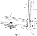
- Fig. 1
- is a perspective view of an arrangement in accordance with the invention for rigidly connecting a lower end of a vertical stake to a horizontal cross-beam adapted to be attached to a longitudinal beam in a carrying structure of a vehicle.
- Fig. 2
- is a view of the outer side of the lower portion of the stack shown in
Fig. 1 . - Fig. 3
- is a cross-sectional view taken along line III-III in
Fig. 1 . - Fig. 4
- is an enlarged view of the right hand portion of
Fig. 3 . - In
figures 1-4 there is presented a preferred embodiment of an arrangement in accordance with the invention. The arrangement comprises ahorizontal cross beam 1 and avertical stake 2 attached to the end of thecross beam 1, by means of anattachment arrangement 3. - As shown in
figure 1 thecross beam 1 preferably has an I-beamshape providing flanges 11 that are used for attaching thecross beam 1 to a vehicle. Further it is shown a fixation arrangement 4 (known per se) including afixation clamp 41 that clamps against theflange 11 of thecross beam 1 to securely fixate thecross beam 1 to a vehicle (not shown). - The
attachment arrangement 3 includes a plurality ofscrews 30 andsleeves stake 2 at anend surface 15, indirectly or directly, of thecross beam 1. Thecross beam 1 is arranged withbores 10 provided withthreads 12. As in the shown example thebores 10 may be deeper than theportion 12 arrange with threads. There are four threadedbores 10 provided in eachcross beam 11, which bores 10 extend in parallel to one and other in the longitudinal direction of thecross beam 1. A plurality of correspondingopenings stake 2, which extend transversally in relation to the longitudinal axis C of thestake 2. Theseopenings cross beam 1. A plurality, preferably four, ofscrews 30 are arranged through theopenings stake 2 and engage thethreads 12 in thecross beam 1 to securely connect the lower end of thestake 2 against theend surface 15 of thecross beam 1. According to a preferred embodiment there is adistance piece 33 arranged between thestake 2 and theend surface 15 of thecross beam 1. Thanks to thedistance piece 33 extra volume is provided within the loading space enclosed by thestakes 2. Thedistance piece 33 is arrange withpassages 330 aligned with the threaded bores 10 ofcross beam 1 for passage of thescrews 30 through thedistance piece 33. Moreover, the end piece facilitates easy use of long screws having ascrew shank outer portion 305 for inter-fit with thethreads 12 in thebore 10 and anintermediate portion 304 of substantial length, preferably at least 30%, more preferred at least 50% of the whole length of the shank, to facilitate beneficial pre-tensioning of the screws. Preferably theintermediate portion 304 is unthreaded, and more preferred with a smaller diameter than the threadedportion 305, to thereby provide for even better pre-tensioning of the screws. - The
distance piece 33 preferably matches the outer boundaries of the cross sectional dimension of thecross beam 1, e.g. preferably having the same height of theend piece 33 as the cross sectional height of thecross beam 1. - In the shown embodiment the
stake 2 is made of metal, having ajacket 20 made from high quality steel. However it is foreseen to use two jacket of sheet metal, e.g. an outer jacket made in aluminum and an inner jacket made in steel. The jackets may be produced from flat metal sheets or extruded, presenting a substantially rectangular cross sectional form. However, it is foreseen that different kind of materials may be used to provide different properties of thestake 2, wherein the same kind ofattachment arrangement 3 is being used. For instance, composite materials may be used to provide properties that are beneficial, e.g. using a structure wherein thestake 2 has ametal jacket 20 and the inside filled with polymeric material, e.g. fiber reinforce polymeric material, either applied as an integral body or applied in the form of different layers within thestake 2. - The lower end of the
stake 2 has oneside 2A facing theend 15 of thecross beam 1 andopposite side 2B facing away from saidend 15. Thescrews 30 are applied throughstake 2 from theside 2B that is facing away from theend 15 of the cross beam, which provides for easy access when handling thescrews 30. - The
screws 30 are preferably of the kind having ahead 301 and a flange 303, wherein the flange is arranged with a tapered/cone shapedinner face 302. Furthermore preferably a mid-portion of thescrew shank 304 is not provided with threads, such that the threadedpart 305 of thescrew 30 merely extends a limited portion along the other end of thescrew 30. - Each
sleeve outer side 2B of the stake. The other end of thesleeve inner side 25 of thestake side 2A facing theend 15 of thecross beam 1. Eachsleeve passage screw 30. Furthermore eachsleeve outer flange portion outer surface 2B of thestake 2. Theflange screw head 301 and screw flange 303 to fit into it, i.e. to house the screw head/flange within the space enclosed byflange outer surface 2B of thestake 2, or at least substantially in level therewith. - The
upper sleeves 32 have rotationally symmetrical shape, i.e. presenting a central passage there through. At the lower end of theflange 320 there is a tapered surface 325 intended to match the tapered/cone shapedsurfaces 302 of the flange 303 of thescrew 30. At other end of thesleeve 32 the through passage is arranged with a slightlylarger diameter 321, than thehole 324 of an intermediate portion comprising the tapered surface 325 at one side. Accordingly in between thecountersink hole 322 and theinner passage portion 321 there is an annual portion having aninner surface 324 that more or less snugly fits on to the unthreaded part of theshank 304 of the screw. - The
lower sleeve 31 may preferably be arranged with aslot 311, having an opening directed down wards, with sufficient width to enable the screw shank 303 to freely move in theslot 311. Hereby the lower most pair ofscrews 30, used for thestake 2, may remain threaded (loosened/not clamped) when astake 2 is taken out (e.g. exchanged), which improves upon the handling of thestakes 2. Moreover it is shown that the counter sank hole of thelower sleeve 31 is deeper than that used for theupper sleeves 32, to provide space for awasher 34 having one tapered side cooperating with the tapered/cone shaped inner face of the screw/flange 303. Moreover it is shown that a lower part 315 of the inner end of thesleeve 31 directly abuts thedistance piece 33 whereas an upper end 316 abuts the inner asurface 25 of thestake 2. - In the shown embodiment the major part of the
stake 2 is made to have a relatively light weight, e.g. thin metal sheet, and is therefore further arranged with reinforcing devices, e.g. reinforcingplates most sleeve 31 up to and further than the upper side of thecross beam 1. Theupper sleeve 32 is arranged to have its inner end 316 to apply pressure on to the reinforcingplates distance piece 33 and theend face 15 via saidreinforcement plates - The
distance piece 33 is preferably arranged withattachment members 331 for application of external devices, e.g. an anchoring device (not shown) to be used for in connection with securing the load, e.g. chain tightners. - The invention is not limited by the examples describe above but by maybe varied within the scope of the appended claims. For instance, it is evident for the skilled person that the sleeves may be in the form of integral parts of the
stake 2 and that then some definitions in the claims, e.g. "flange" and "pressing against the inside of the stake" must be given a broad interpretation to also include this kind of solution. Further it is evident that instead of using a common screw head (hexagonal) as shown, also other screw head forms may be used, e.g. having torques or insex form, wherein there may be no need to have a flange. Moreover it is evident that many other variations may be done without exercising any inventive skill, e.g. to vary the number of screws being used to fit different needs, etc.
Claims (15)
- An arrangement for connecting a lower end of a vertical stake (2) to a horizontal cross-beam (1) adapted to be attached to a beam in a carrying structure of a vehicle, said arrangement comprising:- said vertical stake (2) having a lower end;- said cross-beam (1) having an end surface (15);- a plurality of bores (10) provided with threads (12) in said end surface (15), said threaded bores (10) extending in a longitudinal direction of the cross-beam (1), preferably in parallel to one another,- a plurality of screws (30) engaging the threads (12) of the threaded bores (10) in the cross-beam (1) to connect the lower end of the stake to the end surface (15) of the cross-beam,characterized in that,- a plurality of openings (23, 24) are provided through said lower end of the stake (2), said plurality of openings extending crosswise in relation to a longitudinal axis (C) of the stake and being aligned with the threaded bores (10),- and said plurality of screws (30) extend through openings (23, 24) of the stake (2).
- An arrangement as claimed in claim 1, characterized in that said stake (2) comprises a metal jacket provided with said openings (23, 24) and that sleeves (31, 32) for the screws (30) are arranged in said openings (23, 24).
- An arrangement as claimed in claim 2, wherein the stake (2) has a basically rectangular cross section and has one side (2A) facing the end of the cross-beam and an opposite side (2B) facing away from said end, each screw (30) has a head (301, 303) and a shank (304, 305), and each opening includes a sleeve (31, 32) through which an associated one of the screws (30) extends, each sleeve (31, 32) having one end receiving tightening load from the head (301, 303) of the screw (30) and an opposite end pressed by said tightening load, directly or indirectly, against an inside (25) of the stake side facing the end of the cross-beam (1).
- An arrangement as claimed in claim 2 or 3, wherein the screw (30) is a countersunk screw.
- An arrangement as claimed in claim 2, 3 or 4, wherein the head (301, 3030) of the screw (30) has a tapered/cone shaped inner face (302), preferably a flanged head screw (30) wherein the inner face (302) of the screw flange (303) is tapered/cone shaped.
- An arrangement as claimed in claim 2, 3, 4 or 5, wherein said opposite end of the sleeve (31, 32) has a flange (310, 320) enclosing a counter sink hole (312, 322) arranged to house the screw head (301, 303).
- An arrangement as claimed in claim 2, 3, 4 or 5, wherein a washer (312) having one side shaped to cooperate with the inner face (302) of the screw is interposed between said opposite end of the sleeve (31) and the screw head (301, 303).
- An arrangement as claimed in any one of claims 1-7, wherein a lower end of the stake side facing the end of the cross-beam has a reinforced wall portion (21, 22), preferably in the form of reinforcing plates (21, 22) at the inner side wall of the stake (2).
- An arrangement as claimed in any one of claims 2-8, wherein two of the sleeves (31) form a bottom pair, and each sleeve (31) in the bottom pair has a downward directed longitudinal slot (311) of a width such that the screw shank (304, 305) may pass through the slot.
- An arrangement as claimed in any one of claims 1-8, wherein a distance piece (33) is arranged between the cross-beam (1) and the stake (2), having passages, preferably bores (330), aligned with the threaded bores (10) for passage of the screws through distance piece, wherein preferably the distance piece (33) has dimensions adapted to inter fit with the dimensions of the cross beam (1), preferably having the same height as the cross beam (1)
- An arrangement as claimed in claim 10, wherein the distance piece (33) has attachment members (331) for an external device, preferably in the form of at least one horizontal through bore (331) extending crosswise through the distance piece (33).
- An arrangement as claimed in any one of claims 1-11, wherein the stake (2) is made from composite materials.
- An arrangement as claimed in claim 11, wherein the stake (2) is solid.
- An arrangement as claimed in claim 1, wherein the stake (2) is made from or includes at least one metal jacket (20).
- An arrangement as claimed in claim 14, wherein the stake (2) is made from or includes at least two metal jackets (20).
Applications Claiming Priority (1)
| Application Number | Priority Date | Filing Date | Title |
|---|---|---|---|
| SE1551061A SE539166C2 (en) | 2015-08-10 | 2015-08-10 | An arrangement for rigidly connecting a lower end of a vertical stake to a horizontal cross-beam |
Publications (2)
| Publication Number | Publication Date |
|---|---|
| EP3130529A1 EP3130529A1 (en) | 2017-02-15 |
| EP3130529B1 true EP3130529B1 (en) | 2019-02-20 |
Family
ID=56851377
Family Applications (1)
| Application Number | Title | Priority Date | Filing Date |
|---|---|---|---|
| EP16183562.4A Active EP3130529B1 (en) | 2015-08-10 | 2016-08-10 | An arrangement for rigidly connecting a lower end of a vertical stake to a horizontal cross-beam |
Country Status (2)
| Country | Link |
|---|---|
| EP (1) | EP3130529B1 (en) |
| SE (1) | SE539166C2 (en) |
Cited By (2)
| Publication number | Priority date | Publication date | Assignee | Title |
|---|---|---|---|---|
| EP4079610A1 (en) | 2021-04-23 | 2022-10-26 | Timbtech International AB | A vertical stake arrangement for rigidly connecting a lower end of a vertical stake to a horizontal cross-beam |
| SE2450697A1 (en) * | 2024-06-25 | 2025-12-26 | Timbtech Int Ab | A stake arrangement for connecting a vertical stake to a horizontal cross-beam |
Families Citing this family (3)
| Publication number | Priority date | Publication date | Assignee | Title |
|---|---|---|---|---|
| FI11260U1 (en) * | 2016-05-06 | 2016-05-25 | Alucar Oy | Bank structure and lumber bank bracket |
| RU195985U1 (en) * | 2019-10-22 | 2020-02-12 | Общество с ограниченной ответственностью "Всесоюзный научно-исследовательский центр транспортных технологий" (ООО "ВНИЦТТ") | Wagon body for transportation of long loads |
| EP4094985A1 (en) * | 2021-05-28 | 2022-11-30 | EPSILON Kran GmbH. | Auxiliary frame for a vehicle |
Family Cites Families (12)
| Publication number | Priority date | Publication date | Assignee | Title |
|---|---|---|---|---|
| SE405235B (en) * | 1977-04-28 | 1978-11-27 | Exte Fab | DEVICE AT VEHICLES FOR VEHICLES |
| SE451987B (en) | 1978-09-21 | 1987-11-09 | Exte Fab | DEVICE FOR LOADING A LOADER LARGEABLE LOCATED POST |
| SE451009B (en) | 1984-04-18 | 1987-08-24 | Bergmans Mekaniska Ab | Device for securing upright to vehicle platform |
| SE456235B (en) | 1986-04-25 | 1988-09-19 | Exte Fab | DEVICE BASKET TO LOST ACHIEVELY INSTALL A SUPPORTS IN A RODFUL ELEMENT |
| SE462588B (en) * | 1988-11-28 | 1990-07-23 | Milton Spring | Arrangement for a load bench |
| SE463759B (en) | 1989-05-24 | 1991-01-21 | Exte Fab | DEVICE FOR UNLOCKABLE ANCHORING A POST BY A BANCH IN A VEHICLE'S TRUCK |
| SE470284B (en) | 1992-05-22 | 1994-01-10 | Boerje Baumgarten | Load Bank Construction |
| SE508867C2 (en) | 1997-03-03 | 1998-11-09 | Exte Fab | Mounting device for a load bank |
| SE526445C2 (en) | 2004-04-19 | 2005-09-13 | Laxo Mekan Ab | Post bracket for trucks |
| US7731259B2 (en) * | 2008-09-19 | 2010-06-08 | Consolidated Edison Company Of New York, Inc. | Stake system for flatbed vehicles |
| SE1050633A1 (en) | 2010-06-18 | 2011-05-10 | Exte Fab | Stake Anchoring Arrangements |
| FI124653B (en) | 2012-10-25 | 2014-11-28 | Kuormaväline Oy | Bank Construction |
-
2015
- 2015-08-10 SE SE1551061A patent/SE539166C2/en unknown
-
2016
- 2016-08-10 EP EP16183562.4A patent/EP3130529B1/en active Active
Non-Patent Citations (1)
| Title |
|---|
| None * |
Cited By (3)
| Publication number | Priority date | Publication date | Assignee | Title |
|---|---|---|---|---|
| EP4079610A1 (en) | 2021-04-23 | 2022-10-26 | Timbtech International AB | A vertical stake arrangement for rigidly connecting a lower end of a vertical stake to a horizontal cross-beam |
| SE2450697A1 (en) * | 2024-06-25 | 2025-12-26 | Timbtech Int Ab | A stake arrangement for connecting a vertical stake to a horizontal cross-beam |
| SE547993C2 (en) * | 2024-06-25 | 2026-01-07 | Timbtech Int Ab | A stake arrangement for connecting a vertical stake to a horizontal cross-beam |
Also Published As
| Publication number | Publication date |
|---|---|
| SE1551061A1 (en) | 2017-02-11 |
| SE539166C2 (en) | 2017-05-02 |
| EP3130529A1 (en) | 2017-02-15 |
Similar Documents
| Publication | Publication Date | Title |
|---|---|---|
| EP3130529A1 (en) | An arrangement for rigidly connecting a lower end of a vertical stake to a horizontal cross-beam | |
| EP2230186A2 (en) | Palette, in particular europalette | |
| CA2824702C (en) | Clamp attachment of suspension hanger to aluminum flatbed frame | |
| EP1380462B1 (en) | Fastening device for container | |
| US9738211B2 (en) | Cargo dunnage device | |
| EP4079610A1 (en) | A vertical stake arrangement for rigidly connecting a lower end of a vertical stake to a horizontal cross-beam | |
| DE202013101312U9 (en) | Set of fittings and fixing system for use in the handling and transport of tubular segments such as tower segments of wind turbines | |
| US6503035B1 (en) | Automotive vehicle having a structural reinforcement system for vehicle transport | |
| EP1733955A1 (en) | Device for securing of loads | |
| EP2368759A1 (en) | Method for securing a load and load securing system | |
| DE10312638A1 (en) | Arrangement for securing coil in coil trough in loading floor of transport vehicle has thrust beam transversely above coil trough for attachment to different longitudinal positions of coil trough | |
| EP2582544B1 (en) | Stake anchoring arrangement | |
| EP1900592B1 (en) | Drawing gear for railway vehicles | |
| DE202015002854U1 (en) | Transport device for transporting luggage on two-wheeled vehicles, especially bicycles | |
| EP1385717B1 (en) | Superstructure mounting means | |
| CN211442479U (en) | Reinforced structure of unpowered trailer longeron of security | |
| WO2006024396A2 (en) | Shipping container | |
| EP3702212B1 (en) | Load unit of column-shaped transport containers, assembly of load units and method for securing load | |
| EP3611083B1 (en) | Coupling plate for a saddle coupling | |
| DE102008048404A1 (en) | Load securing device for securing load on loading area of e.g. commercial vehicle, has main body connected with starting point using set of fastening units for fastening transport device to load, where starting point is formed at load | |
| EP2647555B1 (en) | Tarpaulin board assembly, cargo space superstructure and commercial vehicle | |
| KR200392845Y1 (en) | Pallet Tightening Bolts | |
| AT13309U1 (en) | Bordwandzurrösensystem | |
| DE102011112695B4 (en) | Construction element for a cargo bed of a vehicle | |
| DE10343035B4 (en) | Load securing through the vehicle floor with bolt tensioner |
Legal Events
| Date | Code | Title | Description |
|---|---|---|---|
| PUAI | Public reference made under article 153(3) epc to a published international application that has entered the european phase |
Free format text: ORIGINAL CODE: 0009012 |
|
| STAA | Information on the status of an ep patent application or granted ep patent |
Free format text: STATUS: THE APPLICATION HAS BEEN PUBLISHED |
|
| AK | Designated contracting states |
Kind code of ref document: A1 Designated state(s): AL AT BE BG CH CY CZ DE DK EE ES FI FR GB GR HR HU IE IS IT LI LT LU LV MC MK MT NL NO PL PT RO RS SE SI SK SM TR |
|
| AX | Request for extension of the european patent |
Extension state: BA ME |
|
| STAA | Information on the status of an ep patent application or granted ep patent |
Free format text: STATUS: REQUEST FOR EXAMINATION WAS MADE |
|
| 17P | Request for examination filed |
Effective date: 20170814 |
|
| RBV | Designated contracting states (corrected) |
Designated state(s): AL AT BE BG CH CY CZ DE DK EE ES FI FR GB GR HR HU IE IS IT LI LT LU LV MC MK MT NL NO PL PT RO RS SE SI SK SM TR |
|
| GRAP | Despatch of communication of intention to grant a patent |
Free format text: ORIGINAL CODE: EPIDOSNIGR1 |
|
| STAA | Information on the status of an ep patent application or granted ep patent |
Free format text: STATUS: GRANT OF PATENT IS INTENDED |
|
| INTG | Intention to grant announced |
Effective date: 20180329 |
|
| GRAS | Grant fee paid |
Free format text: ORIGINAL CODE: EPIDOSNIGR3 |
|
| RAP1 | Party data changed (applicant data changed or rights of an application transferred) |
Owner name: TIMBTECH AB |
|
| GRAA | (expected) grant |
Free format text: ORIGINAL CODE: 0009210 |
|
| STAA | Information on the status of an ep patent application or granted ep patent |
Free format text: STATUS: THE PATENT HAS BEEN GRANTED |
|
| AK | Designated contracting states |
Kind code of ref document: B1 Designated state(s): AL AT BE BG CH CY CZ DE DK EE ES FI FR GB GR HR HU IE IS IT LI LT LU LV MC MK MT NL NO PL PT RO RS SE SI SK SM TR |
|
| REG | Reference to a national code |
Ref country code: GB Ref legal event code: FG4D |
|
| REG | Reference to a national code |
Ref country code: CH Ref legal event code: EP |
|
| REG | Reference to a national code |
Ref country code: DE Ref legal event code: R096 Ref document number: 602016010043 Country of ref document: DE |
|
| REG | Reference to a national code |
Ref country code: AT Ref legal event code: REF Ref document number: 1097803 Country of ref document: AT Kind code of ref document: T Effective date: 20190315 |
|
| REG | Reference to a national code |
Ref country code: IE Ref legal event code: FG4D |
|
| REG | Reference to a national code |
Ref country code: LT Ref legal event code: MG4D |
|
| REG | Reference to a national code |
Ref country code: NL Ref legal event code: MP Effective date: 20190220 |
|
| REG | Reference to a national code |
Ref country code: NO Ref legal event code: T2 Effective date: 20190220 |
|
| PG25 | Lapsed in a contracting state [announced via postgrant information from national office to epo] |
Ref country code: LT Free format text: LAPSE BECAUSE OF FAILURE TO SUBMIT A TRANSLATION OF THE DESCRIPTION OR TO PAY THE FEE WITHIN THE PRESCRIBED TIME-LIMIT Effective date: 20190220 Ref country code: SE Free format text: LAPSE BECAUSE OF FAILURE TO SUBMIT A TRANSLATION OF THE DESCRIPTION OR TO PAY THE FEE WITHIN THE PRESCRIBED TIME-LIMIT Effective date: 20190220 Ref country code: PT Free format text: LAPSE BECAUSE OF FAILURE TO SUBMIT A TRANSLATION OF THE DESCRIPTION OR TO PAY THE FEE WITHIN THE PRESCRIBED TIME-LIMIT Effective date: 20190620 |
|
| PG25 | Lapsed in a contracting state [announced via postgrant information from national office to epo] |
Ref country code: HR Free format text: LAPSE BECAUSE OF FAILURE TO SUBMIT A TRANSLATION OF THE DESCRIPTION OR TO PAY THE FEE WITHIN THE PRESCRIBED TIME-LIMIT Effective date: 20190220 Ref country code: RS Free format text: LAPSE BECAUSE OF FAILURE TO SUBMIT A TRANSLATION OF THE DESCRIPTION OR TO PAY THE FEE WITHIN THE PRESCRIBED TIME-LIMIT Effective date: 20190220 Ref country code: LV Free format text: LAPSE BECAUSE OF FAILURE TO SUBMIT A TRANSLATION OF THE DESCRIPTION OR TO PAY THE FEE WITHIN THE PRESCRIBED TIME-LIMIT Effective date: 20190220 Ref country code: IS Free format text: LAPSE BECAUSE OF FAILURE TO SUBMIT A TRANSLATION OF THE DESCRIPTION OR TO PAY THE FEE WITHIN THE PRESCRIBED TIME-LIMIT Effective date: 20190620 Ref country code: BG Free format text: LAPSE BECAUSE OF FAILURE TO SUBMIT A TRANSLATION OF THE DESCRIPTION OR TO PAY THE FEE WITHIN THE PRESCRIBED TIME-LIMIT Effective date: 20190520 Ref country code: GR Free format text: LAPSE BECAUSE OF FAILURE TO SUBMIT A TRANSLATION OF THE DESCRIPTION OR TO PAY THE FEE WITHIN THE PRESCRIBED TIME-LIMIT Effective date: 20190521 Ref country code: NL Free format text: LAPSE BECAUSE OF FAILURE TO SUBMIT A TRANSLATION OF THE DESCRIPTION OR TO PAY THE FEE WITHIN THE PRESCRIBED TIME-LIMIT Effective date: 20190220 |
|
| REG | Reference to a national code |
Ref country code: AT Ref legal event code: MK05 Ref document number: 1097803 Country of ref document: AT Kind code of ref document: T Effective date: 20190220 |
|
| PG25 | Lapsed in a contracting state [announced via postgrant information from national office to epo] |
Ref country code: AL Free format text: LAPSE BECAUSE OF FAILURE TO SUBMIT A TRANSLATION OF THE DESCRIPTION OR TO PAY THE FEE WITHIN THE PRESCRIBED TIME-LIMIT Effective date: 20190220 Ref country code: ES Free format text: LAPSE BECAUSE OF FAILURE TO SUBMIT A TRANSLATION OF THE DESCRIPTION OR TO PAY THE FEE WITHIN THE PRESCRIBED TIME-LIMIT Effective date: 20190220 Ref country code: RO Free format text: LAPSE BECAUSE OF FAILURE TO SUBMIT A TRANSLATION OF THE DESCRIPTION OR TO PAY THE FEE WITHIN THE PRESCRIBED TIME-LIMIT Effective date: 20190220 Ref country code: IT Free format text: LAPSE BECAUSE OF FAILURE TO SUBMIT A TRANSLATION OF THE DESCRIPTION OR TO PAY THE FEE WITHIN THE PRESCRIBED TIME-LIMIT Effective date: 20190220 Ref country code: CZ Free format text: LAPSE BECAUSE OF FAILURE TO SUBMIT A TRANSLATION OF THE DESCRIPTION OR TO PAY THE FEE WITHIN THE PRESCRIBED TIME-LIMIT Effective date: 20190220 Ref country code: SK Free format text: LAPSE BECAUSE OF FAILURE TO SUBMIT A TRANSLATION OF THE DESCRIPTION OR TO PAY THE FEE WITHIN THE PRESCRIBED TIME-LIMIT Effective date: 20190220 Ref country code: EE Free format text: LAPSE BECAUSE OF FAILURE TO SUBMIT A TRANSLATION OF THE DESCRIPTION OR TO PAY THE FEE WITHIN THE PRESCRIBED TIME-LIMIT Effective date: 20190220 Ref country code: DK Free format text: LAPSE BECAUSE OF FAILURE TO SUBMIT A TRANSLATION OF THE DESCRIPTION OR TO PAY THE FEE WITHIN THE PRESCRIBED TIME-LIMIT Effective date: 20190220 |
|
| REG | Reference to a national code |
Ref country code: DE Ref legal event code: R097 Ref document number: 602016010043 Country of ref document: DE |
|
| PG25 | Lapsed in a contracting state [announced via postgrant information from national office to epo] |
Ref country code: SM Free format text: LAPSE BECAUSE OF FAILURE TO SUBMIT A TRANSLATION OF THE DESCRIPTION OR TO PAY THE FEE WITHIN THE PRESCRIBED TIME-LIMIT Effective date: 20190220 Ref country code: PL Free format text: LAPSE BECAUSE OF FAILURE TO SUBMIT A TRANSLATION OF THE DESCRIPTION OR TO PAY THE FEE WITHIN THE PRESCRIBED TIME-LIMIT Effective date: 20190220 |
|
| PLBE | No opposition filed within time limit |
Free format text: ORIGINAL CODE: 0009261 |
|
| STAA | Information on the status of an ep patent application or granted ep patent |
Free format text: STATUS: NO OPPOSITION FILED WITHIN TIME LIMIT |
|
| PG25 | Lapsed in a contracting state [announced via postgrant information from national office to epo] |
Ref country code: AT Free format text: LAPSE BECAUSE OF FAILURE TO SUBMIT A TRANSLATION OF THE DESCRIPTION OR TO PAY THE FEE WITHIN THE PRESCRIBED TIME-LIMIT Effective date: 20190220 |
|
| REG | Reference to a national code |
Ref country code: NO Ref legal event code: CHAD Owner name: HAKAN FRANZENS FOERVALTNING AB, SE |
|
| 26N | No opposition filed |
Effective date: 20191121 |
|
| REG | Reference to a national code |
Ref country code: FI Ref legal event code: PCE Owner name: HAKAN FRANZA NS FA RVALTNING AB |
|
| PG25 | Lapsed in a contracting state [announced via postgrant information from national office to epo] |
Ref country code: SI Free format text: LAPSE BECAUSE OF FAILURE TO SUBMIT A TRANSLATION OF THE DESCRIPTION OR TO PAY THE FEE WITHIN THE PRESCRIBED TIME-LIMIT Effective date: 20190220 |
|
| REG | Reference to a national code |
Ref country code: DE Ref legal event code: R119 Ref document number: 602016010043 Country of ref document: DE |
|
| PG25 | Lapsed in a contracting state [announced via postgrant information from national office to epo] |
Ref country code: TR Free format text: LAPSE BECAUSE OF FAILURE TO SUBMIT A TRANSLATION OF THE DESCRIPTION OR TO PAY THE FEE WITHIN THE PRESCRIBED TIME-LIMIT Effective date: 20190220 |
|
| PG25 | Lapsed in a contracting state [announced via postgrant information from national office to epo] |
Ref country code: LU Free format text: LAPSE BECAUSE OF NON-PAYMENT OF DUE FEES Effective date: 20190810 Ref country code: LI Free format text: LAPSE BECAUSE OF NON-PAYMENT OF DUE FEES Effective date: 20190831 Ref country code: CH Free format text: LAPSE BECAUSE OF NON-PAYMENT OF DUE FEES Effective date: 20190831 Ref country code: MC Free format text: LAPSE BECAUSE OF FAILURE TO SUBMIT A TRANSLATION OF THE DESCRIPTION OR TO PAY THE FEE WITHIN THE PRESCRIBED TIME-LIMIT Effective date: 20190220 |
|
| REG | Reference to a national code |
Ref country code: BE Ref legal event code: MM Effective date: 20190831 |
|
| PG25 | Lapsed in a contracting state [announced via postgrant information from national office to epo] |
Ref country code: DE Free format text: LAPSE BECAUSE OF NON-PAYMENT OF DUE FEES Effective date: 20200303 Ref country code: IE Free format text: LAPSE BECAUSE OF NON-PAYMENT OF DUE FEES Effective date: 20190810 Ref country code: FR Free format text: LAPSE BECAUSE OF NON-PAYMENT OF DUE FEES Effective date: 20190831 |
|
| PG25 | Lapsed in a contracting state [announced via postgrant information from national office to epo] |
Ref country code: BE Free format text: LAPSE BECAUSE OF NON-PAYMENT OF DUE FEES Effective date: 20190831 |
|
| GBPC | Gb: european patent ceased through non-payment of renewal fee |
Effective date: 20200810 |
|
| PG25 | Lapsed in a contracting state [announced via postgrant information from national office to epo] |
Ref country code: CY Free format text: LAPSE BECAUSE OF FAILURE TO SUBMIT A TRANSLATION OF THE DESCRIPTION OR TO PAY THE FEE WITHIN THE PRESCRIBED TIME-LIMIT Effective date: 20190220 |
|
| PG25 | Lapsed in a contracting state [announced via postgrant information from national office to epo] |
Ref country code: HU Free format text: LAPSE BECAUSE OF FAILURE TO SUBMIT A TRANSLATION OF THE DESCRIPTION OR TO PAY THE FEE WITHIN THE PRESCRIBED TIME-LIMIT; INVALID AB INITIO Effective date: 20160810 Ref country code: MT Free format text: LAPSE BECAUSE OF FAILURE TO SUBMIT A TRANSLATION OF THE DESCRIPTION OR TO PAY THE FEE WITHIN THE PRESCRIBED TIME-LIMIT Effective date: 20190220 |
|
| PG25 | Lapsed in a contracting state [announced via postgrant information from national office to epo] |
Ref country code: GB Free format text: LAPSE BECAUSE OF NON-PAYMENT OF DUE FEES Effective date: 20200810 |
|
| PG25 | Lapsed in a contracting state [announced via postgrant information from national office to epo] |
Ref country code: MK Free format text: LAPSE BECAUSE OF FAILURE TO SUBMIT A TRANSLATION OF THE DESCRIPTION OR TO PAY THE FEE WITHIN THE PRESCRIBED TIME-LIMIT Effective date: 20190220 |
|
| REG | Reference to a national code |
Ref country code: FI Ref legal event code: PCE Owner name: TIMBTECH INTERNATIONAL AB |
|
| PGFP | Annual fee paid to national office [announced via postgrant information from national office to epo] |
Ref country code: FI Payment date: 20250820 Year of fee payment: 10 |
|
| PGFP | Annual fee paid to national office [announced via postgrant information from national office to epo] |
Ref country code: NO Payment date: 20250821 Year of fee payment: 10 |