EP1380462B1 - Fastening device for container - Google Patents
Fastening device for container Download PDFInfo
- Publication number
- EP1380462B1 EP1380462B1 EP20030015158 EP03015158A EP1380462B1 EP 1380462 B1 EP1380462 B1 EP 1380462B1 EP 20030015158 EP20030015158 EP 20030015158 EP 03015158 A EP03015158 A EP 03015158A EP 1380462 B1 EP1380462 B1 EP 1380462B1
- Authority
- EP
- European Patent Office
- Prior art keywords
- container
- tensioning
- container holder
- fastening apparatus
- longitudinal axis
- Prior art date
- Legal status (The legal status is an assumption and is not a legal conclusion. Google has not performed a legal analysis and makes no representation as to the accuracy of the status listed.)
- Expired - Fee Related
Links
Images


Classifications
-
- B—PERFORMING OPERATIONS; TRANSPORTING
- B60—VEHICLES IN GENERAL
- B60K—ARRANGEMENT OR MOUNTING OF PROPULSION UNITS OR OF TRANSMISSIONS IN VEHICLES; ARRANGEMENT OR MOUNTING OF PLURAL DIVERSE PRIME-MOVERS IN VEHICLES; AUXILIARY DRIVES FOR VEHICLES; INSTRUMENTATION OR DASHBOARDS FOR VEHICLES; ARRANGEMENTS IN CONNECTION WITH COOLING, AIR INTAKE, GAS EXHAUST OR FUEL SUPPLY OF PROPULSION UNITS IN VEHICLES
- B60K15/00—Arrangement in connection with fuel supply of combustion engines or other fuel consuming energy converters, e.g. fuel cells; Mounting or construction of fuel tanks
- B60K15/03—Fuel tanks
- B60K15/063—Arrangement of tanks
- B60K15/067—Mounting of tanks
- B60K15/07—Mounting of tanks of gas tanks
Definitions
- the present invention relates to a fastening device for containers, such as high-pressure vessels, fuel tanks, gas cylinders or the like, to the substructure of the body of a motor vehicle, according to the preamble of claim 1.
- the DE 199 12 671 C1 Such a device for releasably supporting tubular bodies on or at the loading areas of Motor vehicles. With this device, tubular bodies are to be held quickly and without tools safely and immovably on or at the loading areas of motor vehicles and can be released again as quickly as required.
- the DE 199 36 653 A1 by the same applicant discloses a further variant of a device for releasably holding tubular bodies, such as gas cylinders, tubes, tubular containers or the like. This variant is intended as a further development to the aforementioned variant have a Umtschich réelle and an anti-rotation.
- detachable gas bottle holder is known from DE 93 01 537.2 U1 known.
- a device for fixing a plurality of cylindrical containers, such as gas cylinders, in a caddy with a base plate and connected thereto lateral struts, which are distributed along the base plate, wherein the device comprises strips, in particular of flat iron, on the uppermost layer of the containers are arranged across the width of the stack between two struts and occupy the shape of the containers of the uppermost layer, the apparatus having clamping means for clamping the entire bottle package consisting of a plurality of gas cylinders.
- This device is used to transport a variety the same gas bottles, for example, on a trailer or a truck.
- the fuel tank such as a gas cylinder
- the tension bands comprise the circumference of the body facing away from the base of the body
- a commercially available turnbuckle has been provided in practice, one side of which is connected to one end of the tension band and the other side is screwed by means of the fastening screws on the L-shaped container holder.
- a fastening device according to the preamble of claim 1 is known, in which a container by means of two clamping straps in two container holders, where the straps are attached, is supported.
- the two container holder are formed in a half-shell shape and have a complementary to the outer contour of the container support surface in which the container rests positively.
- the DE 200 11 592 U1 Similar solutions are known, the DE 200 11 592 U1 the well-known art, as in the WO 98/02324 is shown, expressly criticized.
- Object of the present invention is therefore such known from practice fastening devices for containers, such as high-pressure tank, fuel tanks, gas cylinders, or the like, further develop such that a fuel tank while avoiding the aforementioned disadvantages safely against twisting, slipping or even tearing permanently on the base of Body of a motor vehicle can be attached.
- a fastening device for containers such as high-pressure vessels, fuel tanks, gas cylinders, or the like, proposed, which are to be fixed to the base of the body of a motor vehicle by means of this fastening device, said fastening device has at least two at least partially comprehensive clamping bands and two Container holders to which the straps are attached.
- the longitudinal axis of the container is preferably oriented transversely to the vehicle longitudinal axis, wherein the container holders extend on either side of the container parallel to its longitudinal axis, and wherein the container is disposed between the container holders.
- At least one of the two container holders is V-shaped in cross-section with a technological tip so that at least one attachment point of the container-facing leg of the V-shaped container holder lies on the underside within the container contour projected perpendicular to the base, wherein the strap and container holder largely conform to the container cross-section and thereby include the container cross-section as much as possible.
- V-shaped design of the container holder cross-section that the container as far as possible against the left and right of the container him facing shoulders or legs of the respective adjacent V-shaped container holder can be supported, so that the base to be fixed container in principle, as in a contoured on his tray or shell rests, from which this can not move out even in sudden acceleration or deceleration, as may occur, for example, in a head-on collision or a rear impact.
- the V-shaped container holder is advantageously torsionally rigid and thus more stable than conventional, for example L-shaped, container holder with the same wall thicknesses.
- the V-shaped container holder takes, for example, even those forces that can occur in a sharp acceleration or deceleration of the vehicle due to the inertia of the container in the horizontal direction, easily complete.
- Such forces are absorbed by the respective facing legs of the V-shaped container holder and of these on the one hand - depending on whether a pushing or pulling force acting on the leg facing the container - passed accordingly as Switzerlandoder thrust in the substructure and on the other hand as thrust - or tensile force on the outer leg derived in the substructure.
- the straps fastened to the two container holders ensure in an advantageous manner that the containers enclosed between the V-shaped container holders do not roll over the respectively affected flank over the V-shaped container holder and thus out of the container can move out of the two container holders and the substructure formed pan or shell.
- the fastening device according to the invention provides for the first time advantageously an economically manufacturable, cost-effective solution of the above-known from practice problems, which is also feasible in a mass production beyond.
- the two V-shaped container holder can be screwed in a conventional manner for mounting against the subfloor, welded, dotted or crimped.
- the attachment of the container holder to the subfloor is merely to be interpreted so that the maximum forces can be intercepted and introduced into the subfloor.
- the tensioning band is fastened to the container holder by means of a turnbuckle such that the tensile forces prevailing in the tensioning band can in turn be introduced into the container holder via a tensioning screw as tensile forces and as far as possible without shearing forces.
- a turnbuckle provides the ability to impart exactly the predetermined clamping force on the strap so that the fixed with a fastening device according to the invention attached to the base container is optimally secured and permanently secured against unwanted twisting, commuting, or move out of its position ,
- a commercially available turnbuckle can advantageously be used at correspondingly low prices, which in turn has a positive effect on the production costs of the fastening device according to the invention.
- a further preferred embodiment proposes that the tension lock interposed between the container holder and the clamping band end has two, preferably cylindrical, clamping bodies with a threaded bore oriented perpendicular to the extension direction of the clamping body, in which the clamping screw engages, wherein the first clamping body is located in the tip of the clamping body.
- shaped container holder is rotatably disposed about its longitudinal axis and the second clamping body is rotatably encompassed by a tab on the clamping band end about its longitudinal axis, wherein the tab and the container holder each having a recess through which the clamping screw are screwed through the second clamping body into the first clamping body can.
- connection of the clamping band end by means of the turnbuckle with the mounting bracket ensures by the mutually rotatable articulation of the turnbuckle ends on Spannbandende or on the mounting bracket that no unwanted moments in the power flow from the strap can occur to the container holder. This is a completely kink-free connection can be realized.
- the clamping bodies of the turnbuckles can be hooked into the V-shaped container holder with the least possible installation effort, so that this preferred embodiment is not only accessible to mass production due to the ease of assembly, but also represents a particularly cost-effective alternative.
- the clamping bolt can be easily hooked into the strap-like strap end. The same applies to the extremely simple handling when connecting the two clamping body with the clamping screw.
- the tension band is fastened to the container holder by means of a tensioning bracket in such a way that the tension forces prevailing on the tension band can in turn be introduced into the container holder via a tension bolt as tensile forces and as far as possible without shear forces.
- the interposed between the container holder and the clamping band end clamping bracket is designed as a double-T-bolt or H-bolt, the two preferably at least semi-cylindrical.
- Clamping body with a vertical to the extension direction of the clamping body oriented connecting bolt wherein the first clamping body by means of a recess in the tip of the V-shaped container holder is rotatably suspended about its longitudinal axis and the second clamping body is rotatably encompassed by a tab on the clamping band end about its longitudinal axis, wherein the tab is a recess has, through which the second clamping body of the clamping bracket is suspended through.
- the fastening device has in a further preferred embodiment, two V-shaped container holder with recesses for the passage of clamping screws or clamping bolts for associated clamping body of turnbuckles or clamps, and has either two turnbuckles or a turnbuckle and a clamping bracket per strap.
- the leg of the V-shaped container holder facing away from the container is supported against the vehicle longitudinal axis parallel to the vehicle longitudinal axis and thus preferably oriented perpendicular to the direction of orientation of the container holder Reinforcing ribs that form so-called "crash boxes" as a crumple zone in a rear impact.
- the reinforcing ribs on both sides of the container can be assigned to each container holder. It is also conceivable to provide only on one side of such reinforcing ribs.
- the dimensioning of these components can be further optimized in this way, so that they can be designed to save weight and material as light and slim as possible.
- the support of the container holder can be screwed against the reinforcing ribs, for example, for a permanent fixation, welded, dotted, crimped or otherwise executed. The same applies to the attachment of the reinforcing ribs on the substructure.
- the clamping body is designed as a cylindrical sleeve. This is one of the cheapest and easiest to manufacture variants.
- the angle ⁇ facing the container between the substructure and the container-facing leg of the V-shaped container holder is between 110 ° and 130 °, in particular 120 °.
- the angle ⁇ facing the container between the substructure and the container-facing leg of the V-shaped container holder is between 110 ° and 130 °, in particular 120 °.
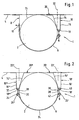
- FIG. 1 is a simplified schematic section of a first exemplary embodiment of a fastening device 1 according to the invention for container 2, such as high-pressure vessels, fuel tanks, or here a gas cylinder, or the like, for their attachment to the base 4 of the body not shown in detail of a motor vehicle not shown.
- container 2 such as high-pressure vessels, fuel tanks, or here a gas cylinder, or the like
- the container 2 is at least partially enclosed by a tension band 6 and arranged between two container holders 8 and 10.
- the left container holder 8 is formed in the variant shown here as an L-shaped container holder.
- the clamping band 6 with at least one fastening means 12, which may be formed, for example, as a fastening screw mounted.
- the right in this representation container holder 10 has a V-shaped cross-section. Whose two legs 14 and 16 are fastened to the base 4 with fastening means, not shown, such as screws or a welded joint, spot welding or Krimpthetic.
- the tip 18 of the V-shaped container holder 10 faces away from the base 4.
- the attachment point 20 of the container 2 facing leg 14 of the V-shaped right container holder 10 with the bottom 4 is within the container contour projected perpendicular to the base 4, as the dashed line 22 is intended to illustrate.
- both clamping band 6 and container holder 10 nestle as far as possible on the container cross-section 24 of the container 2, wherein they include the container cross-section 24 as far as possible.
- FIG. 2 is a further exemplary embodiment of a fastening device 1 according to the invention for container 2 shown for their attachment to the base 4 of the body of a motor vehicle not shown in a simplified schematic representation.
- the container 2 is held by two V-shaped container holders 10 'and 10 ".
- the clamping band 6 is in this illustration with its left end, which is formed into a tab 26", by means of a tensioning bracket 28 with the tip 18'. 'of the left container holder 10 "connected.
- the clamping bracket 28 has a clamping bolt 30.
- the Spannhbügel 28 may be formed as a double-T-bolt or H-bolt, which has two, preferably at least semi-cylindrical, clamping body 32 and 34, respectively in the top 18 "of the V-shaped container holder 10" and in contrast are hung in the tab 26 "of the tension band 6.
- the right clamping band end is also formed in the form of a tab 26 '.
- the right clamping band end is connected by means of a turnbuckle 36 to the tip 18 'of the right container holder 10'.
- the turnbuckle 36 has a tightening screw 38 by means of which the tension forces prevailing in the tightening strap 6 can in turn be introduced as tensile forces and as far as possible without shear forces into the receptacle holder 10 '.
- the turnbuckle 36 also has two, preferably cylindrical, clamping bodies 40 and 42 with a substantially perpendicular to the direction of extension of the clamping body oriented - not shown here - threaded hole into which the clamping screw 38 engages.
- the first clamping body 40 is rotatably supported in the tip 18 'of the V-shaped container holder 10' about its longitudinal axis.
- the second clamping body 42 is rotatably encompassed by the tab 26 'at the right clamping band end about its longitudinal axis.
- attachment points 20 'and 20 "of each of the left and right in the representation shown here the container 2 facing legs 14" and 14' are located on the bottom 4 within the projected perpendicular to the base 4 container contour, which in turn here with the dashed lines 22nd should be indicated 'or 22'.
- FIG. 3 reproduced three-dimensional view of a schematically simplified illustration of an exemplary embodiment illustrates the fixation of the container 2 on the partially illustrated substructure 4.
- the V-shaped container holder 10 '' is shown in the left part of the picture.
- This has recesses 44 in which the clamping body 32 of the here designed as a double T-bolt or H-bolt tension bracket 28 are mounted.
- the left clamping band ends of the tensioning straps 6 are designed as straps 26 ", which have straps 26" Recesses 46 for the passage of the tension bracket 28.
- a fitting 48 of the container 2 is shown on the right edge of the picture. Further, a reinforcing rib 50 is fixed to the base 4 for additional support of the right container holder 10 '.
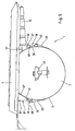
- FIG. 4 is again in a schematic simplified three-dimensional view obliquely from below the only partially illustrated substructure with the already in Fig. 3 shown exemplary embodiment of the fastening device 1 according to the invention fixed container 2 shown.
- the view reproduced here focuses on the right side of the container. 2
- FIG. 4 In the left picture section of Fig. 4 is the fitting 48 recognizable with the associated modules.
- the container 2 is braced against the container holders 10 'and 10 "by means of two tension bands 6.
- the right end of the tension bands 6 is in each case designed as a tab 26.
- the tab 26' has recesses 52 through which the tensioning screw 38 of the turnbuckle 36 passes.
- the clamping body 42 through which the clamping screw 38 passes, is suspended in the lug 26 '
- the clamping body 42 is shown in the embodiment variant shown here as a cylindrical sleeve with a threaded bore 54 oriented substantially perpendicular to the extension direction of the clamping body 42 38 engages through a recess 56, which is arranged in the top of the V-shaped container holder 10 'through it into the clamping body 40 therein.
- the container holder 10 ' is additionally supported with its side facing away from the container 2 leg 16' against reinforcing ribs 50, which in turn are attached to the bottom 4.
- the reinforcing ribs 50 are preformed so that they can absorb as much kinetic energy as possible in an impact.
- Fig. 5 is the in Figures 3 and 4 illustrated embodiment again shown schematically simplified in a side view. From this representation, it is very clear that the container 2 in a kind of pan or shell, which is formed by the bottom 4 and the two container holders 10 'and 10 "and the container facing legs 14' and 14" to the Contour or contiguous to the container cross-section of the container 2, rests, the contour of the container 2 from the clamping band 6, the left of the container 2 by means of the clamping bracket 28 with the container holder 10 "is braced and which right of the container 2 with the turnbuckle 36th is attached to the container holder 10 'is included as far as possible.
- the tension band 6, the tension bow 28, the container holder 10 "of the affected portion of the subfloor 4, the container holder 10 'and the turnbuckle 36 a container 2 fully wrapped around the clamping ring, which conforms so well to the contour or the container cross-section
- FIGS. 1 to 5 are the same or equivalent parts or components provided with the same reference numerals, for ease of illustration.
- the present invention thus provides for the first time a fastening device for containers, such as fuel tanks, gas cylinders, or the like, which are to be mounted by means of the fastening device to the base of the body of a motor vehicle.
- this fastening device at least two clamping bands at least partially comprising the container, and two container holder to which the clamping bands are attached.
- the longitudinal axis of the container is preferably oriented transversely to the vehicle longitudinal axis, wherein the container holders extend on either side of the container parallel to the longitudinal axis of the container, and wherein the container is disposed between the container holders. It is provided for the first time that at least one of the two container holder is formed in cross-section V-shaped with the technological V-tip from the base.
- At least one attachment point of the container-facing leg of the V-shaped container holder is disposed on the underside within the container contour projected perpendicular to the substructure, wherein the clamping band and container holder largely conform to the container cross section and thereby include the container cross section as much as possible.
Description
Die vorliegende Erfindung betrifft eine Befestigungsvorrichtung für Behälter, wie beispielsweise Hochdruckbehälter, Kraftstofftanks, Gasflaschen oder dergleichen, am Unterbau der Karosserie eines Kraftfahrzeuges, nach dem Oberbegriff des Anspruchs 1.The present invention relates to a fastening device for containers, such as high-pressure vessels, fuel tanks, gas cylinders or the like, to the substructure of the body of a motor vehicle, according to the preamble of claim 1.
Aus der
Weiterhin sind unterschiedlich ausgestaltete Vorrichtungen zur lösbaren Halterung von rohrförmigen Körpern, wie Gasflaschen, Rohre, rohrförmige Behälter oder dergleichen bekannt geworden.Furthermore, differently designed devices for releasably supporting tubular bodies, such as gas cylinders, tubes, tubular containers or the like have become known.
So offenbart beispielsweise die
Eine weitere Ausführungsform einer lösbaren Gasflaschenhalterung ist aus der
Ferner ist aus der
Diese vorgenannten lösbaren Vorrichtungen haben lediglich die zeitweilige Halterung von rohrförmigen Behältern, wie beispielsweise Gasflaschen, für deren Transport von einem Ort zum anderen Ort zum Zweck. Die damit transportierten Behälter bleiben während des Transports verschlossen und weisen beispielsweise im Falle von Gasflaschen häufig Schutzkappen auf, die über das Anschlussfitting geschraubt sind, damit dieses vor äußeren Einwirkungen aller Art geschützt ist. Während des Transports erfolgt keine Nutzung des im transportierten Behälter bevorrateten Inhalts.These aforementioned releasable devices have only the temporary support of tubular containers, such as gas cylinders, for their transport from one place to another place for the purpose. The containers thus transported remain closed during transport and, for example in the case of gas cylinders, frequently have protective caps which are screwed over the connection fitting so that it is protected against external influences of all kinds. During transport, no use is made of the contents stored in the transported container.
Aus der Praxis ist es beispielsweise bei mit Erdgas (CNG) betriebenen Kraftfahrzeugen bekannt geworden, die erforderlichen Kraftstoffbehälter am Unterbau der Karosserie zu befestigen, statt diese beispielsweise im Kofferraum unterzubringen, um den dort nutzbaren Innenraum nicht unnötig zu verkleinern. Derlei Kraftstoffbehälter beispielsweise für Erdgas sind wegen des hohen Überdrucks von beispielsweise 200 bar meistens in Form von zylindrischen Flaschen ausgestaltet. Zur Befestigung solcher Kraftstoffbehälter am Unterbau der Karosserie werden in der Praxis zwei quer zur Fahrzeuglängsachse voneinander beanstandete Behälterhalter vorzugsweise mit L-förmigem Querschnitt, wie beispielsweise L-förmige Montagewinkel, verwendet. Dazwischen wird der Kraftstoffbehälter, wie beispielsweise eine Gasflasche, mit zwei Spannbändern befestigt, wobei die Längsachse des Behälters quer zur Fahrzeuglängsachse bzw. parallel zu den Behälterhaltern orientiert ist. Die Spannbänder umfassen den dem Unterbau der Karosserie abgewandten Umfang des Kraftstoffbehälters und sind mit waagrecht bzw. parallel zum Fahrzeugboden oder Unterbau orientierten Befestigungsschrauben an den L-förmigen Behälterhaltern angeschraubt. Mit einer solchen aus der Praxis bekannten Befestigungsvorrichtung sind jedoch noch keine Spannkräfte auf das Spannband aufbringbar. Dementsprechend ist in der Praxis ein handelsübliches Spannschloss vorgesehen worden, dessen eine Seite mit einem Ende des Spannbandes verbunden ist und dessen andere Seite mittels der Befestigungsschrauben am L-förmigen Behälterhalter angeschraubt ist.From practice, it is known, for example, in vehicles powered by natural gas (CNG), to attach the required fuel tank to the substructure of the body, instead of accommodating them, for example, in the trunk, not to unnecessarily reduce the interior usable there. Such fuel tanks, for example, for natural gas are mostly designed in the form of cylindrical bottles because of the high pressure of, for example, 200 bar. For attachment of such fuel tank on the base of the body two transversely to the vehicle longitudinal axis spaced apart container holder preferably with L-shaped cross-section, such as L-shaped mounting bracket used in practice. In between, the fuel tank, such as a gas cylinder, is fastened with two tension straps, the longitudinal axis of the tank being oriented transversely to the vehicle longitudinal axis or parallel to the container holders. The tension bands comprise the circumference of the body facing away from the base of the body Fuel tank and are screwed with horizontally or parallel to the vehicle floor or base oriented mounting screws on the L-shaped container holders. However, with such known from practice fastening device no clamping forces on the strap are still applicable. Accordingly, a commercially available turnbuckle has been provided in practice, one side of which is connected to one end of the tension band and the other side is screwed by means of the fastening screws on the L-shaped container holder.
Diese Art der Befestigung von Gasflaschen oder dergleichen am Unterbau der Karosserie eines Kraftfahrzeuges hat jedoch den wesentlichen Nachteil, dass die Befestigungsschrauben, mit denen auf der einen Seite der Gasflasche das eine Ende des Spannbandes am L-förmigen Behälterhalter angeschraubt ist und mit denen auf der anderen Seite der Gasflasche das dem L-förmigen Behälterhalter benachbarte Ende des Spannschlosses angeschraubt ist, beim Erzeugen einer Spannkraft mit der Spannschraube des Spannschlosses nicht - wie bei Schrauben üblich - auf Zug belastet werden, sondern mit Quer- bzw. Scherkräften beaufschlagt werden. Dementsprechend weisen diese bekannten Befestigungsvorrichtungen nur geringe Belastungsreserven auf. Demzufolge besteht die Gefahr, dass bei einem Unfall oder bereits bei einem besonders scharfen Bremsvorgang oder Lastwechsel des Kraftfahrzeuges schon so hohe Kräfte aufgrund der Trägheit der Gasflasche auf die Befestigungsvorrichtung einwirken, dass die Befestigungsschrauben wegen der darin resultierenden hohen Quer- bzw. Scherkräfte abreißen und damit die Gasflasche sich losreißen kann.However, this type of attachment of gas cylinders or the like to the base of the bodywork of a motor vehicle has the significant disadvantage that the fastening screws with which on one side of the gas cylinder, one end of the strap is screwed to the L-shaped container holder and with those on the other Side of the gas cylinder which is screwed to the L-shaped container holder adjacent end of the turnbuckle, when generating a clamping force with the clamping screw of the turnbuckle not - as usual with screws - are loaded on train, but are subjected to transverse or shear forces. Accordingly, these known fastening devices have only low load reserves. Consequently, there is a risk that in an accident or already at a particularly sharp braking or load change of the motor vehicle so high forces due to the inertia of the gas cylinder act on the fastening device that demolish the fastening screws because of the resulting high transverse and shear forces and thus the gas bottle can break loose.
Auch im normalen Betrieb eines Kraftfahrzeuges ist diese aus der Praxis bekannte Befestigungsvorrichtung für Gasflaschen am Unterbau der Karosserie eines Kraftfahrzeuges mit Mängeln behaftet. So haben Fahrzeugerprobungen gezeigt, dass die mit dieser bekannten Befestigungsvorrichtung montierten Gasflaschen aufgrund der beim Fahren unvermeidlichen Erschütterungen dazu neigen, sich um ihre Längsachse zu verdrehen. Dies führt in der Folge zu Dichtungsproblemen im Anschlussbereich der Gasflasche. Ferner treten unerwünschte Pendel- oder Schwenkbewegungen der Gasflasche in Fahrzeuglängsrichtung auf, selbst wenn die L-förmigen Behälterhalter möglichst dicht an den Durchmesser der Gasflasche platziert werden. Diese Quer- bzw. Rollbewegungen der Gasflasche treten häufig unter elastischer Verformung der Befestigungsvorrichtung sowohl beim Beschleunigen als auch beim Verzögern des Kraftfahrzeuges auf und können auf die Dauer zu einer Ermüdung der Befestigungsschrauben führen, die dann brechen, was schlussendlich zu den bereits vorstehend diskutierten gefährlichen Folgen, wie Gasaustritt führt.Even in normal operation of a motor vehicle, this known from practice fastening device for gas cylinders on the substructure of the body of a motor vehicle is fraught with defects. Thus, vehicle tests have shown that the gas cylinders mounted with this known fastening device tend to twist about their longitudinal axis due to the inevitable during driving vibrations. As a result, this leads to sealing problems in the connection area of the gas cylinder. Furthermore, undesired pendulum or pivotal movements of the gas cylinder occur in the vehicle longitudinal direction, even if the L-shaped container holder are placed as close as possible to the diameter of the gas cylinder. These transverse or rolling movements of the gas cylinder often occur under elastic deformation of the fastening device during both acceleration and deceleration of the motor vehicle and can lead in the long run to a fatigue of the mounting screws, which then break, which ultimately leads to the dangerous consequences already discussed above how gas leakage leads.
Aus der
Aufgabe der vorliegenden Erfindung ist es demzufolge derlei aus der Praxis bekannte Befestigungsvorrichtungen für Behälter, wie beispielsweise Hochdruckbehälter, Kraftstofftanks, Gasflaschen, oder dergleichen, derart weiterzuentwickeln, dass ein Kraftstofftank unter Vermeidung der vorgenannten Nachteile sicher gegen Verdrehen, Verrutschen oder gar Losreißen dauerhaft am Unterbau der Karosserie eines Kraftfahrzeuges befestigt werden kann.Object of the present invention is therefore such known from practice fastening devices for containers, such as high-pressure tank, fuel tanks, gas cylinders, or the like, further develop such that a fuel tank while avoiding the aforementioned disadvantages safely against twisting, slipping or even tearing permanently on the base of Body of a motor vehicle can be attached.
Diese Aufgabe wird gelöst durch die Merkmale des Anspruchs 1.This object is achieved by the features of claim 1.
Hierzu wird erfindungsgemäß eine Befestigungsvorrichtung für Behälter, wie beispielsweise Hochdruckbehälter, Kraftstofftanks, Gasflaschen, oder dergleichen, vorgeschlagen, die am Unterbau der Karosserie eines Kraftfahrzeuges mit Hilfe dieser Befestigungsvorrichtung zu fixieren sind, wobei diese Befestigungsvorrichtung wenigstens zwei den Behälter zumindest teilweise umfassende Spannbänder aufweist und zwei Behälterhalter, an denen die Spannbänder befestigt sind. Die Längsachse des Behälters ist vorzugsweise quer zur Fahrzeuglängsachse orientiert, wobei die Behälterhalter sich beiderseits des Behälters parallel zu dessen Längsachse erstrecken, und wobei der Behälter zwischen den Behälterhaltern angeordnet ist. Dabei wird erstmals vorgeschlagen, dass wenigstens einer der beiden Behälterhalter im Querschnitt V-förmig ausgebildet ist mit vom Unterbau wegweisender Spitze, so dass wenigstens ein Befestigungspunkt des dem Behälter zugewandten Schenkels des V-förmigen Behälterhalters am Unterboden innerhalb der senkrecht zum Unterbau projizierten Behälterkontur liegt, wobei Spannband und Behälterhalter sich weitestgehend an den Behälterquerschnitt anschmiegen und dabei den Behälterquerschnitt soweit als möglich umfassen.For this purpose, a fastening device for containers, such as high-pressure vessels, fuel tanks, gas cylinders, or the like, proposed, which are to be fixed to the base of the body of a motor vehicle by means of this fastening device, said fastening device has at least two at least partially comprehensive clamping bands and two Container holders to which the straps are attached. The longitudinal axis of the container is preferably oriented transversely to the vehicle longitudinal axis, wherein the container holders extend on either side of the container parallel to its longitudinal axis, and wherein the container is disposed between the container holders. In this case, it is proposed for the first time that at least one of the two container holders is V-shaped in cross-section with a groundbreaking tip so that at least one attachment point of the container-facing leg of the V-shaped container holder lies on the underside within the container contour projected perpendicular to the base, wherein the strap and container holder largely conform to the container cross-section and thereby include the container cross-section as much as possible.
Damit wird erstmals in vorteilhafter Weise eine optimale Umfassung des am Unterbau eines Kraftfahrzeuges zu befestigenden Behälters erzielt. Auf diese Weise sind die aus der Praxis nachteilig empfundenen Drehbewegungen des Behälters um seine Längsachse bei Erschütterungen, die im üblichen Fahrzeugbetrieb zwangsläufig auftreten, ausgeschlossen. Ferner ist damit vermieden, dass der Behälter bei Beschleunigungen oder Verzögerungen des Fahrzeugs ungewollte Pendelbewegungen oder Schwenkbewegungen beispielsweise um die gemeinsame Berührungslinie seiner Außenkontur mit dem Unterbau ausführen kann. Insbesondere ist durch die V-förmige Gestaltung des Behälterhalterquerschnitts sichergestellt, dass sich der Behälter möglichst flächig gegen die jeweils links und rechts des Behälters ihm zugewandten Schultern bzw. Schenkel des jeweilig benachbarten V-förmigen Behälterhalters abstützen kann, so dass der am Unterbau zu fixierende Behälter im Prinzip wie in einer auf seine Kontur angepassten Wanne oder Schale ruht, aus der dieser sich selbst bei schlagartigen Beschleunigungen oder Verzögerungen, wie sie beispielsweise bei einem Frontalzusammenstoss oder einem Heckaufprall auftreten können, nicht herausbewegen kann.For the first time, advantageously, an optimum enclosure of the container to be fastened to the substructure of a motor vehicle is achieved. In this way, the rotational movements of the container, which are disadvantageously perceived from practice, are excluded about its longitudinal axis in the event of vibrations that inevitably occur in normal vehicle operation. Furthermore, it is thus avoided that the container during acceleration or deceleration of the vehicle unwanted oscillations or pivotal movements, for example, the common line of contact of his External contour can perform with the substructure. In particular, it is ensured by the V-shaped design of the container holder cross-section that the container as far as possible against the left and right of the container him facing shoulders or legs of the respective adjacent V-shaped container holder can be supported, so that the base to be fixed container in principle, as in a contoured on his tray or shell rests, from which this can not move out even in sudden acceleration or deceleration, as may occur, for example, in a head-on collision or a rear impact.
Der V-förmige Behälterhalter ist bei gleichen Wandstärken vorteilhaft verwindungssteifer und damit stabiler als herkömmliche, beispielsweise L-förmige, Behälterhalter. Dabei nimmt der V-förmige Behälterhalter beispielsweise auch jene Kräfte, die bei einem scharfen Beschleunigen oder Verzögern des Fahrzeuges aufgrund der Trägheit des Behälters in horizontaler Richtung auftreten können, problemlos vollständig auf. Derlei Kräfte werden über die jeweils zugewandten Schenkel des V-förmigen Behälterhalters aufgenommen und von diesen einerseits - je nach dem ob eine Schub- oder Zugkraft auf den dem Behälter zugewandten Schenkel einwirkt - entsprechend als Zugoder Schubkraft in den Unterbau weitergeleitet als auch andererseits entsprechend als Schub- oder Zugkraft über den äußeren Schenkel in den Unterbau abgeleitet. Die an den beiden Behälterhaltern befestigten Spannbänder stellen dabei in vorteilhafter Weise sicher, dass der zwischen den V-förmigen Behälterhaltern eingeschmiegte Behälter sich nicht über die jeweils betroffene Flanke über den V-förmigen Behälterhalter abrollen und damit aus der aus den beiden Behälterhaltern und dem Unterbau gebildeten Wanne bzw. Schale herausbewegen kann.The V-shaped container holder is advantageously torsionally rigid and thus more stable than conventional, for example L-shaped, container holder with the same wall thicknesses. In this case, the V-shaped container holder takes, for example, even those forces that can occur in a sharp acceleration or deceleration of the vehicle due to the inertia of the container in the horizontal direction, easily complete. Such forces are absorbed by the respective facing legs of the V-shaped container holder and of these on the one hand - depending on whether a pushing or pulling force acting on the leg facing the container - passed accordingly as Zugoder thrust in the substructure and on the other hand as thrust - or tensile force on the outer leg derived in the substructure. The straps fastened to the two container holders ensure in an advantageous manner that the containers enclosed between the V-shaped container holders do not roll over the respectively affected flank over the V-shaped container holder and thus out of the container can move out of the two container holders and the substructure formed pan or shell.
Damit ist die aus der Praxis bekannte Gefahr des Losreißens des Behälters, insbesondere eines Kraftstofftanks oder einer Gasflasche oder dergleichen ausgeschlossen und es kann nicht mehr zu den entsprechenden Folgeschäden kommen.Thus, the known from practice risk of tearing of the container, in particular a fuel tank or a gas cylinder or the like is excluded and it can no longer come to the corresponding consequential damage.
Darüber hinaus bietet die erfindungsgemäße Befestigungsvorrichtung erstmalig in vorteilhafter Weise eine wirtschaftlich herzustellende, kostengünstige Lösung der vorstehend aus der Praxis bekannten Probleme, die darüber hinaus auch in einer Serienproduktion realisierbar ist. Hierzu können die beiden V-förmigen Behälterhalter in an sich bekannter Weise zu deren Montage gegen den Unterboden verschraubt, verschweißt, gepunktet oder gekrimpt werden. Die Befestigung der Behälterhalter am Unterboden ist lediglich so auszulegen, dass die maximal auftretenden Kräfte damit abgefangen und in den Unterboden eingeleitet werden können.In addition, the fastening device according to the invention provides for the first time advantageously an economically manufacturable, cost-effective solution of the above-known from practice problems, which is also feasible in a mass production beyond. For this purpose, the two V-shaped container holder can be screwed in a conventional manner for mounting against the subfloor, welded, dotted or crimped. The attachment of the container holder to the subfloor is merely to be interpreted so that the maximum forces can be intercepted and introduced into the subfloor.
Vorteilhafte Weiterbildungen der Erfindung ergeben sich aus den Merkmalen der Unteransprüche.Advantageous developments of the invention will become apparent from the features of the dependent claims.
So ist in einer bevorzugten Ausführungsform der erfindungsgemäßen Befestigungsvorrichtung vorgesehen, dass das Spannband vermittels eines Spannschlosses derart am Behälterhalter befestigt ist, dass die im Spannband herrschenden Zugkräfte über eine Spannschraube wiederum als Zugkräfte und weitestgehend ohne Scherkräfte in den Behälterhalter einleitbar sind. Damit werden die bei aus der Praxis bekannten Befestigungsvorrichtungen nachteiligen Scherkräfte in den dort verwendeten Befestigungsschrauben vermieden. Diese Scherkräfte führten im Stand der Technik nachteilig relativ rasch zu einer Überlastung der Befestigungsschrauben und zu deren Bruch. Infolgedessen konnten sich die gemäß dem aus der Praxis bekannten Stand der Technik befestigten Behälter bereits bei ungünstigen Beschleunigungsverhältnissen aufgrund des Berstens der Befestigungsschrauben losreißen, wobei derlei ungünstige Beschleunigungsverhältnisse noch weit unter denjenigen Verzögerungs- oder Beschleunigungswerten lagen, die bei einem Unfall auftreten können.Thus, in a preferred embodiment of the fastening device according to the invention, it is provided that the tensioning band is fastened to the container holder by means of a turnbuckle such that the tensile forces prevailing in the tensioning band can in turn be introduced into the container holder via a tensioning screw as tensile forces and as far as possible without shearing forces. Thus, the known in practice from the fastening devices disadvantageous shear forces in the fastening screws used there avoided. These shearing forces resulted disadvantageously relatively quickly in the prior art to overload the fastening screws and their breakage. As a result, the containers fixed according to the prior art known in the art could break loose even under unfavorable conditions of acceleration due to the rupture of the mounting bolts, with such unfavorable acceleration ratios still well below those deceleration or acceleration values that may occur in an accident.
Darüber hinaus bietet die Verwendung eines Spannschlosses die Möglichkeit, exakt die vorausbestimmte Spannkraft auf das Spannband aufzuprägen, so dass der ein mit einer erfindungsgemäßen Befestigungsvorrichtung am Unterbau befestigter Behälter optimal fixiert und dauerhaft gegen ein unerwünschtes Verdrehen, Pendeln, oder sich aus seiner Lage Herausbewegen gesichert ist.In addition, the use of a turnbuckle provides the ability to impart exactly the predetermined clamping force on the strap so that the fixed with a fastening device according to the invention attached to the base container is optimally secured and permanently secured against unwanted twisting, commuting, or move out of its position ,
Zudem kann in vorteilhafter Weise ein handelsübliches Spannschloss zu entsprechend günstigen Preisen Verwendung finden, was sich wiederum positiv auf die Herstellungskosten der erfindungsgemäßen Befestigungsvorrichtung auswirkt.In addition, a commercially available turnbuckle can advantageously be used at correspondingly low prices, which in turn has a positive effect on the production costs of the fastening device according to the invention.
Nicht zuletzt ist für die Befestigung des Spannbandes vermittels eines Spannschlosses am Behälterhalter ein optimaler Kraftfluss bzw. eine sehr gute Kraftableitung der im Spannband vorherrschenden Zugkraft über das Spannschloss in den Behälterhalter und von diesem in den Fahrzeugunterbau gewährleistet. Unerwünschte Spitzen im Kräfteverlauf oder gar Momente, die zu punktuellen Überlastungen oder zu einem Knicken von Bauteilen führen könnten, sind damit vermieden.Last but not least, an optimal force flow or a very good power dissipation of the tension prevailing in the tension band over the turnbuckle is ensured in the container holder and of this in the vehicle body for the attachment of the clamping band by means of a turnbuckle on the container holder. Unwanted peaks in the course of forces or even moments that could lead to punctual overloads or buckling of components, are thus avoided.
Eine weiter bevorzugte Ausführungsform schlägt vor, dass das zwischen dem Behälterhalter und dem Spannbandende zwischengeschaltete Spannschloss zwei, vorzugsweise zylindrische, Spannkörper mit einer senkrecht zur Erstreckungsrichtung des Spannkörpers orientierten Gewindebohrung aufweist, in welche die Spannschraube eingreift, wobei der erste Spannkörper in der Spitze des V-förmigen Behälterhalters um seine Längsachse drehbar angeordnet ist und der zweite Spannkörper von einer Lasche am Spannbandende um seine Längsachse drehbar umfasst ist, wobei die Lasche und der Behälterhalter jeweils eine Ausnehmung aufweisen, durch welche die Spannschraube durch den zweiten Spannkörper hindurch in den ersten Spannkörper hineingeschraubt werden kann. Diese erfindungsgemäße Ausgestaltungsvariante der Verbindung des Spannbandendes vermittels des Spannschlosses mit dem Befestigungshalter stellt durch die beiderseits drehbare Anlenkung der Spannschlossenden am Spannbandende bzw. am Befestigungshalter sicher, dass keinerlei unerwünschte Momente im Kraftfluss vom Spannband zum Behälterhalter auftreten können. Damit ist eine vollständig knickfreie Verbindung realisierbar.A further preferred embodiment proposes that the tension lock interposed between the container holder and the clamping band end has two, preferably cylindrical, clamping bodies with a threaded bore oriented perpendicular to the extension direction of the clamping body, in which the clamping screw engages, wherein the first clamping body is located in the tip of the clamping body. shaped container holder is rotatably disposed about its longitudinal axis and the second clamping body is rotatably encompassed by a tab on the clamping band end about its longitudinal axis, wherein the tab and the container holder each having a recess through which the clamping screw are screwed through the second clamping body into the first clamping body can. This inventive variant of the connection of the clamping band end by means of the turnbuckle with the mounting bracket ensures by the mutually rotatable articulation of the turnbuckle ends on Spannbandende or on the mounting bracket that no unwanted moments in the power flow from the strap can occur to the container holder. This is a completely kink-free connection can be realized.
Die dabei ausschließlich zu berücksichtigenden Zugkräfte sind einer numerischen Analyse jederzeit problemlos zugänglich, so dass eine optimale Dimensionierung der erfindungsgemäßen Befestigungsvorrichtung in Abhängigkeit der zu erwartenden Kraftverhältnisse bereits in der Planungsphase am Rechner mit bekannten CAD-Verfahren und/oder Finite-Elemente-Methoden im voraus durchgeführt werden kann. Damit können entsprechend teuere Feldversuche oder gar aufwendige Crashtests entfallen oder zumindest auf ein minimales Maß beschränkt werden. Die sich hier in vorteilhafter Weise ergebenden Kosteneinsparpotentiale sind beachtlich.The tensile forces which are to be taken into account exclusively are readily accessible to a numerical analysis at any time, so that optimum dimensioning of the fastening device according to the invention is already carried out in advance in the planning phase on the computer with known CAD methods and / or finite element methods can be. This means that correspondingly expensive field tests or even expensive crash tests can be omitted or at least limited to a minimum. Which Here advantageously resulting cost saving potentials are considerable.
Durch die Vorsehung entsprechender Ausnehmungen oder Schlitze in der Spitze des V-förmigen Behälterhalter lassen sich die Spannkörper der Spannschlösser mit möglichst geringem Montageaufwand in den V-förmigen Behälterhalter einhängen, so dass diese bevorzugte Ausführungsvariante aufgrund der einfachen Montierbarkeit nicht nur einer Serienproduktion zugänglich ist, sondern eine besonders kostengünstige Alternative darstellt. Analoges trifft auf die Verbindungsstelle zwischen dem in dieser Ausgestaltungsvariante laschenartigen Spannbandende und dem ihm zugeordneten Spannschlossende zu. Auch hier lässt sich der Spannbolzen problemlose in das laschenartige Spannbandende einhängen. Gleiches gilt hinsichtlich der extrem einfachen Handhabung beim Verbinden der beiden Spannkörper mit der Spannschraube.By providing corresponding recesses or slots in the tip of the V-shaped container holder, the clamping bodies of the turnbuckles can be hooked into the V-shaped container holder with the least possible installation effort, so that this preferred embodiment is not only accessible to mass production due to the ease of assembly, but also represents a particularly cost-effective alternative. The same applies to the connection point between the strap-type clamping strap end and the turnbuckle end associated with it in this embodiment variant. Again, the clamping bolt can be easily hooked into the strap-like strap end. The same applies to the extremely simple handling when connecting the two clamping body with the clamping screw.
In einer weiter bevorzugten Ausführungsform ist das Spannband vermittels eines Spannbügels derart am Behälterhalter befestigt, dass die am Spannband herrschenden Zugkräfte über einen Spannbolzen wiederum als Zugkräfte und weitestgehend ohne Scherkräfte in den Behälterhalter einleitbar sind. Hier ergeben sich wiederum die bereits vorstehend zur Lösung mit dem Spannschloss mit Spannschraube diskutierten Vorteile.In a further preferred embodiment, the tension band is fastened to the container holder by means of a tensioning bracket in such a way that the tension forces prevailing on the tension band can in turn be introduced into the container holder via a tension bolt as tensile forces and as far as possible without shear forces. Here, in turn, the advantages discussed above for the solution with the turnbuckle with clamping screw arise.
Gemäss einer weiter bevorzugten Variante der erfindungsgemäßen Befestigungsvorrichtung ist vorgesehen, dass der zwischen dem Behälterhalter und dem Spannbandende zwischengeschaltete Spannbügel als Dopppel-T-Bolzen oder als H-Bolzen ausgebildet ist, der zwei vorzugsweise wenigstens halbzylindrische. Spannkörper mit einem senkrecht zur Erstreckungsrichtung der Spannkörper orientierten Verbindungsbolzen aufweist, wobei der erste Spannkörper vermittels einer Ausnehmung in der Spitze des V-förmigen Behälterhalters um dessen Längsachse drehbar einhängbar ist und der zweite Spannkörper von einer Lasche am Spannbandende um dessen Längsachse drehbar umfasst ist, wobei die Lasche eine Ausnehmung aufweist, durch welche der zweite Spannkörper des Spannbügels hindurch einhängbar ist. Auch hier ergeben sich die bereits vorstehend diskutierten Vorteile hinsichtlich leichter Montierbarkeit, kostengünstiger Umsetzung und klarer Dimensionierung der entsprechenden Bauteile-durch diesbezügliche Berechnungen im Vorfeld der Serienproduktion.According to a further preferred variant of the fastening device according to the invention it is provided that the interposed between the container holder and the clamping band end clamping bracket is designed as a double-T-bolt or H-bolt, the two preferably at least semi-cylindrical. Clamping body with a vertical to the extension direction of the clamping body oriented connecting bolt, wherein the first clamping body by means of a recess in the tip of the V-shaped container holder is rotatably suspended about its longitudinal axis and the second clamping body is rotatably encompassed by a tab on the clamping band end about its longitudinal axis, wherein the tab is a recess has, through which the second clamping body of the clamping bracket is suspended through. Again, there are the advantages already discussed above in terms of ease of assembly, cost-effective implementation and clear dimensioning of the corresponding components-through related calculations in the run-up to mass production.
Die erfindungsgemäße Befestigungsvorrichtung weist in einer weiter bevorzugten Ausführungsform zwei V-förmige Behälterhalter mit Ausnehmungen zum Durchgriff von Spannschrauben oder Spannbolzen für zugeordnete Spannkörper von Spannschlössern oder Spannbügeln auf, und verfügt entweder über zwei Spannschlösser oder über ein Spannschloss und einen Spannbügel pro Spannband. Damit wird in vorteilhafter Weise sichergestellt, dass der am Unterbau zu befestigende Behälter rund um vermittels Zugkräften am Unterboden fixiert und dort dauerhaft gesichert ist. Ein unerwünschtes Bewegen des Behälters während des Betriebs des Fahrzeugs und insbesondere ein unerwünschtes Losreißen desselben bei einem Unfall oder dergleichen ist ausgeschlossen.The fastening device according to the invention has in a further preferred embodiment, two V-shaped container holder with recesses for the passage of clamping screws or clamping bolts for associated clamping body of turnbuckles or clamps, and has either two turnbuckles or a turnbuckle and a clamping bracket per strap. This ensures in an advantageous manner that the container to be fastened to the substructure is fixed to the subfloor by means of tensile forces and is permanently secured there. An undesired movement of the container during operation of the vehicle and in particular an unwanted tearing of the same in an accident or the like is excluded.
Gemäss einer weiter bevorzugten Ausführungsform stützt sich der dem Behälter abgewandte Schenkel des V-förmigen Behälterhalters gegen parallel zur Fahrzeuglängsachse und damit in bevorzugter Weise senkrecht zur Orientierungsrichtung des Behälterhalters orientierte Verstärkungsrippen ab, die sogenannte "Crashboxen" als Knautschzone bei Heckaufprall bilden. Dabei können die Verstärkungsrippen beiderseits des Behälters jedem Behälterhalter zugeordnet werden. Es ist ebenso denkbar lediglich auf einer Seite derlei Verstärkungsrippen vorzusehen. Vermittels der Verstärkungsrippen können besonders große, schlagartig auftretende Kräfte, wie sie bei Unfällen unvermeidbar sind, mit leicht beherrschbaren geringen Flächenbelastungen über die vergleichsweise große Kontaktfläche der Verstärkungsrippen zum Unterbau noch besser abgeleitet werden, als dies der Fall ist bei einer Verwendung von Behälterhaltern ohne Verstärkungsrippen.According to a further preferred embodiment, the leg of the V-shaped container holder facing away from the container is supported against the vehicle longitudinal axis parallel to the vehicle longitudinal axis and thus preferably oriented perpendicular to the direction of orientation of the container holder Reinforcing ribs that form so-called "crash boxes" as a crumple zone in a rear impact. The reinforcing ribs on both sides of the container can be assigned to each container holder. It is also conceivable to provide only on one side of such reinforcing ribs. By means of the reinforcing ribs particularly large, suddenly occurring forces, which are unavoidable in accidents, with easily controllable low surface loads over the comparatively large contact surface of the reinforcing ribs to the substructure can be derived even better than is the case when using container holders without reinforcing ribs.
Insbesondere kann auf diese Weise die Dimensionierung dieser Bauteile weiter optimiert werden, so dass diese zur Einsparung von Gewicht und Material so leicht und schlank als möglich ausgelegt werden können. Dabei kann die Abstützung der Behälterhalter gegen die Verstärkungsrippen beispielsweise für eine dauerhafte Fixierung geschraubt, geschweißt, gepunktet, gekrimpt oder anderweitig ausgeführt werden. Analoges gilt für die Befestigung der Verstärkungsrippen am Unterbau.In particular, the dimensioning of these components can be further optimized in this way, so that they can be designed to save weight and material as light and slim as possible. In this case, the support of the container holder can be screwed against the reinforcing ribs, for example, for a permanent fixation, welded, dotted, crimped or otherwise executed. The same applies to the attachment of the reinforcing ribs on the substructure.
In einer weiter bevorzugten Ausführungsform der erfindungsgemäßen Befestigungsvorrichtung ist der Spannkörper als zylindrische Hülse ausgebildet. Dies ist eine der kostengünstigsten und am einfachsten herzustellenden Varianten.In a further preferred embodiment of the fastening device according to the invention, the clamping body is designed as a cylindrical sleeve. This is one of the cheapest and easiest to manufacture variants.
Gemäss einer weiter bevorzugten Ausführungsform beträgt der dem Behälter zugewandte Winkel α zwischen dem Unterbau und dem behälterzugewandten Schenkel des V-förmigen Behälterhalters zwischen 110° und 130°, insbesondere 120°. Auf diese Weise wird mit geringem Aufwand vorteilhaft eine optimale Anschmiegung des zu befestigenden Behälters an die vom Unterbau und den Behälterhaltern gebildete Wanne oder Schale ermöglicht. Insbesondere bietet die dabei einem Sechseck angelehnte entstehende Kontur gerade bei zylindrischen Behältern, wie beispielsweise Gasflaschen, einen optimalen Halt derselben.According to a further preferred embodiment, the angle α facing the container between the substructure and the container-facing leg of the V-shaped container holder is between 110 ° and 130 °, in particular 120 °. In this way is advantageous with little effort allows optimal fitting of the container to be fastened to the trough or shell formed by the base and the container holders. In particular, the resulting a hexagon resulting contour especially in cylindrical containers, such as gas cylinders, an optimal grip of the same.
Die Erfindung wird nachfolgend in Ausführungsbeispielen anhand der Figuren der Zeichnung näher erläutert. Es zeigt:
- Fig. 1
- einen schematisch vereinfachten Schnitt durch eine erste beispielhafte Ausführungsform einer erfindungsgemäßen Befestigungsvorrichtung;
- Fig. 2
- einen schematisch vereinfachten Schnitt durch eine zweite beispielhafte Ausführungsform einer erfindungsgemäßen Befestigungsvorrichtung;
- Fig. 3
- eine dreidimensionale, schematisch vereinfachte Darstellung mit einem Blickwinkel schräg von unten auf eine beispielhafte Ausführungsform einer erfindungsgemäßen Befestigungsvorrichtung;
- Fig. 4
- eine weitere dreidimensionale, schematisch vereinfachte Ansicht schräg von unten der in
Fig. 3 gezeigten Ausführungsform; und - Fig. 5
- eine schematisch vereinfachte Ansicht von der Seite der in
Fig. 3 und4 gezeigten beispielhaften Ausführungsform.
- Fig. 1
- a simplified schematic section through a first exemplary embodiment of a fastening device according to the invention;
- Fig. 2
- a simplified schematic section through a second exemplary embodiment of a fastening device according to the invention;
- Fig. 3
- a three-dimensional, schematically simplified representation with a viewing angle obliquely from below on an exemplary embodiment of a fastening device according to the invention;
- Fig. 4
- another three-dimensional, schematically simplified view obliquely from below the in
Fig. 3 embodiment shown; and - Fig. 5
- a simplified schematic view from the side of in
Fig. 3 and4 shown exemplary embodiment.
In
Der Behälter 2 ist zumindest teilweise von einem Spannband 6 umfasst und zwischen zwei Behälterhaltern 8 und 10 angeordnet. Der linke Behälterhalter 8 ist in der hier dargestellten Variante als L-förmiger Behälterhalter ausgebildet. An diesem ist das Spannband 6 mit wenigstens einem Befestigungsmittel 12, das beispielsweise als Befestigungsschraube ausgebildet sein kann, montiert. Der in dieser Darstellung rechte Behälterhalter 10 weist einen V-förmigen Querschnitt auf. Dessen beide Schenkel 14 und 16 sind mit nicht näher dargestellten Befestigungsmitteln, wie beispielsweise Schrauben oder einer Schweißverbindung, Punktschweißverbindung oder Krimpverbindung am Unterbau 4 befestigt. Die Spitze 18 des V-förmigen Behälterhalters 10 weist vom Unterbau 4 weg nach unten. Der Befestigungspunkt 20 des dem Behälter 2 zugewandten Schenkels 14 des V-förmigen rechten Behälterhalters 10 mit dem Unterboden 4 liegt innerhalb der senkrecht zum Unterbau 4 projizierten Behälterkontur, wie dies die gestrichelte Linie 22 verdeutlichen soll. Dabei schmiegen sich sowohl Spannband 6 als auch Behälterhalter 10 weitestgehend an den Behälterquerschnitt 24 des Behälters 2 an, wobei diese dabei den Behälterquerschnitt 24 soweit als möglich umfassen.The
In
Der Spannbügel 28 weist einen Spannbolzen 30 auf. Der Spanhbügel 28 kann dabei als Doppel-T-Bolzen oder als H-Bolzen ausgebildet sein, wobei dieser zwei, vorzugsweise wenigstens halbzylindrische, Spannkörper 32 bzw. 34 aufweist, die entsprechend in der Spitze 18" des V-förmigen Behälterhalter 10" und demgegenüber in der Lasche 26" des Spannbandes 6 eingehängt sind.The clamping
Auf der in dieser Darstellung rechten Seite ist das rechte Spannbandende ebenfalls in Form einer Lasche 26' ausgebildet. Das rechte Spannbandende ist vermittels eines Spannschlosses 36 mit der Spitze 18' des rechten Behälterhalters 10' verbunden. Das Spannschloss 36 weist eine Spannschraube 38 auf vermittels derer die im Spannband 6 herrschenden Zugkräfte wiederum als Zugkräfte und weitestgehend ohne Scherkräfte in den Behälterhalter 10' einleitbar sind.On the right side in this illustration, the right clamping band end is also formed in the form of a tab 26 '. The right clamping band end is connected by means of a turnbuckle 36 to the tip 18 'of the right container holder 10'. The
Das Spannschloss 36 verfügt weiterhin über zwei, vorzugsweise zylindrische, Spannkörper 40 und 42 mit einer im wesentlichen senkrecht zur Erstreckungsrichtung des Spannkörpers orientierten - hier nicht näher dargestellten - Gewindebohrung, in welche die Spannschraube 38 eingreift. Der erste Spannkörper 40 ist in der Spitze 18' des V-förmigen Behälterhalters 10' um seine Längsachse drehbar gehalten. Der zweite Spannkörper 42 ist von der Lasche 26 ' am rechten Spannbandende um seine Längsachse drehbar umfasst. Die Laschen 26` und 26" als auch die Spitzen 18' und 18" der Behälterhalter 10' und 10" weisen - in dieser Darstellung nicht näher gezeigte - Ausnehmungen auf, durch welche die Spannschraube 38 bzw. der Spannbolzen 30 hindurch in den jeweiligen Spannkörper geschraubt bzw. mit diesem einstückig verbunden werden kann.The turnbuckle 36 also has two, preferably cylindrical, clamping
Die Befestigungspunkte 20' bzw. 20" der jeweils links und rechts in der hier gezeigten Darstellung dem Behälter 2 zugewandten Schenkel 14" bzw. 14' liegen am Unterboden 4 innerhalb der senkrecht zum Unterbau 4 projizierten Behälterkontur, was hier wiederum mit den gestrichelten Linien 22" bzw. 22' angedeutet sein soll.The attachment points 20 'and 20 "of each of the left and right in the representation shown here the
Die in
Am rechten Bildrand ist ein Fitting 48 des Behälters 2 gezeigt. Ferner ist eine Verstärkungsrippe 50 am Unterbau 4 befestigt zur zusätzlichen Abstützung des rechten Behälterhalters 10'.On the right edge of the picture, a fitting 48 of the
In
Im linken Bildabschnitt von
Der Behälterhalter 10' ist zusätzlich mit dessen vom Behälter 2 abgewandtem Schenkel 16' gegen Verstärkungsrippen 50 abgestützt, die ihrerseits am Unterboden 4 befestigt sind. Die Verstärkungsrippen 50 sind so vorgeformt, dass sie möglichst viel kinetische Energie bei einem Aufprall absorbieren können.The container holder 10 'is additionally supported with its side facing away from the
In
Dabei bilden das Spannband 6, der Spannbügel 28, der Behälterhalter 10" der betroffene Abschnitt des Unterbodens 4, der Behälterhalter 10' und das Spannschloss 36 einen den Behälter 2 voll umschlingenden Spannring aus, der sich so gut an dessen Kontur bzw. den Behälterquerschnitt anschmiegt, dass keine nennenswerten Restzwischenräume verbleiben. Damit ist eine optimale Fixierung und dauerhafte Befestigung des Behälters 2 am Unterboden gewährleistet, ohne dass dieser sich aufgrund der beim normalen Betrieb des Fahrzeugs auftretenden Erschütterungen verdrehen könnte oder sich aufgrund irgendwelcher auf ihn von außen einwirkender Kräfte beim Beschleunigen oder Verzögern des Fahrzeugs oder gar bei einem Unfall aus seiner Lage herausbewegen könnte.In this case, the
In den
Die vorliegende Erfindung schafft damit erstmals eine Befestigungsvorrichtung für Behälter, wie beispielsweise Kraftstofftanks, Gasflaschen, oder dergleichen vor, die vermittels der Befestigungsvorrichtung am Unterbau der Karosserie eines Kraftfahrzeuges montiert werden sollen. Bei dieser Befestigungsvorrichtung weist wenigstens zwei den Behälter zumindest teilweise umfassende Spannbänder auf, und zwei Behälterhalter, an denen die Spannbänder befestigt sind. Die Längsachse des Behälters ist vorzugsweise quer zur Fahrzeuglängsachse orientiert, wobei die Behälterhalter sich beiderseits des Behälters parallel zur Längsachse des Behälters erstrecken, und wobei der Behälter zwischen den Behälterhaltern angeordnet ist. Dabei ist erstmals vorgesehen, dass wenigstens einer der beiden Behälterhalter im Querschnitt V-förmig ausgebildet ist mit vom Unterbau wegweisender V-Spitze. Damit ist wenigstens ein Befestigungspunkt des dem Behälter zugewandten Schenkels des V-förmigen Behälterhalters am Unterboden innerhalb der senkrecht zum Unterbau projizierten Behälterkontur angeordnet, wobei Spannband und Behälterhalter sich weitestgehend an den Behälterquerschnitt anschmiegen und dabei den Behälterquerschnitt soweit als möglich umfassen.The present invention thus provides for the first time a fastening device for containers, such as fuel tanks, gas cylinders, or the like, which are to be mounted by means of the fastening device to the base of the body of a motor vehicle. In this fastening device, at least two clamping bands at least partially comprising the container, and two container holder to which the clamping bands are attached. The longitudinal axis of the container is preferably oriented transversely to the vehicle longitudinal axis, wherein the container holders extend on either side of the container parallel to the longitudinal axis of the container, and wherein the container is disposed between the container holders. It is provided for the first time that at least one of the two container holder is formed in cross-section V-shaped with the groundbreaking V-tip from the base. Thus, at least one attachment point of the container-facing leg of the V-shaped container holder is disposed on the underside within the container contour projected perpendicular to the substructure, wherein the clamping band and container holder largely conform to the container cross section and thereby include the container cross section as much as possible.
- 11
- Befestigungsvorrichtungfastening device
- 22
- Behältercontainer
- 44
- Unterbausubstructure
- 66
- Spannbandstrap
- 88th
- Behälterhaltercontainer holder
- 1010
- Behälterhaltercontainer holder
- 10'10 '
- Behälterhaltercontainer holder
- 10"10 "
- Behälterhaltercontainer holder
- 1212
- Befestigungsmittelfastener
- 1414
- Schenkelleg
- 1616
- Schenkelleg
- 1818
- Spitzetop
- 18'18 '
- Spitzetop
- 18"18 "
- Spitzetop
- 2020
- Befestigungspunktattachment point
- 2222
- Linieline
- 2424
- BehälterquerschnittContainer cross-section
- 26'26 '
- Lascheflap
- 26"26 "
- Lascheflap
- 2828
- Spannbügeltensioning bow
- 3030
- Spannbolzenclamping bolt
- 3232
- Spannkörpertensioning body
- 3434
- Spannkörpertensioning body
- 3636
- Spannschlossturnbuckle
- 3838
- Spannschraubeclamping screw
- 4040
- Spannkörpertensioning body
- 4242
- Spannkörpertensioning body
- 4444
- Ausnehmungrecess
- 4646
- Ausnehmungrecess
- 4848
- Fittingfitting
- 5050
- Verstärkungsrippereinforcing rib
- 5252
- Ausnehmungrecess
- 5454
- Gewindebohrungthreaded hole
- 5656
- Ausnehmungrecess
Claims (12)
- A fastening apparatus (1) for containers (2) such as highpressure tanks, fuel tanks, gas cylinders or the like, on the underbody (4) of the car body of a motor vehicle, comprising at least two tightening straps (6) which enclose the container (2) at least in part and two container holders (8) to which the tightening straps are fastened, with the container (2) being arranged between the container holders (8) and the tightening strap (6, 6', 6") sitting close to the container cross section (24) as far as possible and enclosing the container cross section (24) as far as possible, characterized in that the container holders (8) extend on either side of the container (2) parallel to the longitudinal axis of the container (2), and at least one of the two container holders (10, 10', 10") is arranged to be V-shaped in the cross section with a tip (18, 18', 18") facing away from the underbody (4), so that at least one fastening point (20, 20', 20") of the limb (14, 14', 14") of the V-shaped container holder (10) which faces the container (2) lies on the underbody (4) within the container contour (22, 22', 22") projected perpendicularly to the underbody (4).
- A fastening apparatus (1) according to claim 1, characterized in that the tightening strap (6) being fastened by means of a turnbuckle (36) to the container holder (10, 10') in such a way that the tensile forces prevailing in the tightening strap (6) can be introduced again by way of a tensioning screw (38) as tensile forces into the container holder (10, 10').
- A fastening apparatus (1) according to claim 2, characterized in that the turnbuckle (36) interposed between the container holder (10, 10') and the tightening strap end (26') comprises two tensioning bodies (40, 42) with a threaded borehole (54) oriented perpendicularly to the direction of extension of the tensioning body (40, 42), in which borehole the tensioning screw (38) engages, with the first tensioning body (40) being arranged in the tip (18, 18') of the V-shaped container holder (10, 10') in a manner rotatable about its longitudinal axis, and the second tensioning body (42) is enclosed rotatably about its longitudinal axis by a bracket (26') at the end of the tightening strap, with the bracket (26') and the container holder (10') respectively comprising a recess (52), through which the tensioning screw (38) can be screwed through the second tensioning body (42) into the first tensioning body (40).
- A fastening apparatus (1) according to one of the claims 1 to 3, characterized in that the tensioning strap (6) is fastened by means of a clamping bracket (28) to the container holder (10") in such a way that the tensile forces prevailing in the tensioning strap (6) can be introduced by way of a tensioning bolt (30) as tensile forces again into the container holder (10").
- A fastening apparatus (1) according to claim 4, characterized in that the clamping bracket (28) interposed between the container holder (10") and the tightening strap end (26") is arranged as a double T-bolt or as an H-bolt which comprises two preferably semi-cylindrical tensioning bodies (32, 34) with a connecting pin (30) oriented perpendicularly to the direction of extension of the tensioning bodies (32, 34), with the first tensioning body (32), as a result of a recess (44) in the tip (18") of the V-shaped container holder (10"), being rotatably suspendable about its longitudinal axis and the second tensioning body (34) being rotatably encompassed about its longitudinal axis by a bracket (26") at the end of the tightening strap, with the bracket (26") having a recess (46) by means of which the second tensioning body (34) of the tensioning bracket can be suspended through the same.
- A fastening apparatus (1) according to one of the claims 1 to 5, characterized in that the two container holders (10, 10', 10") are arranged to be V-shaped in their cross section and are provided with recesses for the penetration of tensioning screws (38) or tensioning bolts (30) for associated tensioning bodies (32, 34, 40, 42) of turnbuckles (36) or clamping brackets (28), and the fastening apparatus (1) comprises either two turnbuckles (36) or one turnbuckle (36) and a clamping bracket (28) per tightening strap (6).
- A fastening apparatus (1) according to one of the claims 1 to 6, characterized in that the limb (16, 16', 16") of the V-shaped container holder (10, 10', 10") facing away from the container (2) rests on reinforcing ribs (50) oriented parallel to the longitudinal axis of the vehicle.
- A fastening apparatus (1) according to one of the claims 1 to 7, characterized in that the tensioning body (32, 34, 40, 42) is arranged as a cylindrical sleeve (54).
- A fastening apparatus (1) according to one of the claims 1 to 8, characterized in that the angle α facing the container (2) between the underbody (4) and the limb (14, 14', 14") of the V-shaped container holder (10, 10', 10") which faces the container is between 110° and 130°.
- A fastening apparatus (1) according to claim 9, characterized in that the angle α facing the container (2) between the underbody (4) and the limb (14, 14', 14") of the V-shaped container holder (10, 10', 10") which faces the container is between 120°.
- A fastening apparatus (1) according to one of the preceding claims, characterized in that the longitudinal axis of the container (2) is oriented transversally to the longitudinal axis of the vehicle.
- A fastening apparatus (1) according to one of the preceding claims, characterized in that the two tensioning bodies (40, 42) are arranged cylindrically.
Applications Claiming Priority (2)
| Application Number | Priority Date | Filing Date | Title |
|---|---|---|---|
| DE10230635 | 2002-07-08 | ||
| DE2002130635 DE10230635A1 (en) | 2002-07-08 | 2002-07-08 | Fastening device for containers |
Publications (3)
| Publication Number | Publication Date |
|---|---|
| EP1380462A2 EP1380462A2 (en) | 2004-01-14 |
| EP1380462A3 EP1380462A3 (en) | 2006-12-20 |
| EP1380462B1 true EP1380462B1 (en) | 2011-11-23 |
Family
ID=29723790
Family Applications (1)
| Application Number | Title | Priority Date | Filing Date |
|---|---|---|---|
| EP20030015158 Expired - Fee Related EP1380462B1 (en) | 2002-07-08 | 2003-07-04 | Fastening device for container |
Country Status (2)
| Country | Link |
|---|---|
| EP (1) | EP1380462B1 (en) |
| DE (1) | DE10230635A1 (en) |
Cited By (1)
| Publication number | Priority date | Publication date | Assignee | Title |
|---|---|---|---|---|
| WO2022204744A1 (en) * | 2021-04-01 | 2022-10-06 | Cryoshelter Gmbh | Mounting system for fastening a cryogenic container to a vehicle frame |
Families Citing this family (17)
| Publication number | Priority date | Publication date | Assignee | Title |
|---|---|---|---|---|
| US7270209B2 (en) * | 2004-08-10 | 2007-09-18 | General Motors Corporation | Modular fuel storage system for a vehicle |
| SE529231C2 (en) * | 2005-10-17 | 2007-06-05 | Volvo Lastvagnar Ab | Motor vehicle with rear-mounted battery box |
| JP5040566B2 (en) * | 2007-09-28 | 2012-10-03 | 三菱自動車工業株式会社 | Electric vehicle battery fixing structure |
| DE102007049837A1 (en) * | 2007-10-18 | 2009-05-14 | GM Global Technology Operations, Inc., Detroit | Fastening arrangement for retaining strap of a gas tank holding device |
| DE102008034629A1 (en) * | 2008-07-25 | 2009-04-02 | Daimler Ag | Storage container fastening system for lorry, has console elements for accommodation of storage containers and selectively directly or indirectly fixed at side members by connection element, where elements have screwing openings |
| US8465057B2 (en) * | 2008-08-27 | 2013-06-18 | GM Global Technology Operations LLC | Rear integration of a suspension system and fuel tanks in fuel cell vehicles |
| DE102008059844B4 (en) * | 2008-12-01 | 2013-01-31 | Man Truck & Bus Ag | Device for attaching one or more containers to a chassis component |
| DE102009007923B4 (en) * | 2009-02-06 | 2013-02-28 | Manfred Bätzold | Holding device for compressed air tank |
| JP2013503077A (en) * | 2009-08-25 | 2013-01-31 | スラユット・ポシリスク | CNG container jigs and fixtures for automobiles |
| CN103158536A (en) * | 2011-12-09 | 2013-06-19 | 上海汽车集团股份有限公司 | Gas bottle bandage fixing and connecting structure |
| CN103158535A (en) * | 2011-12-09 | 2013-06-19 | 上海汽车集团股份有限公司 | Gas cylinder fixing device with automatic compensation of tightening force |
| DE202012103321U1 (en) * | 2012-08-31 | 2012-09-20 | EES-Autogas Technologiezentrum UG (haftungsbeschränkt) | Device for arranging gas containers in a trailer |
| US9434333B2 (en) | 2014-09-23 | 2016-09-06 | Agility Fuel Systems, Inc. | Bumper bar |
| SE538571C2 (en) | 2014-12-19 | 2016-09-20 | Scania Cv Ab | Attachment device for containers on a vehicle, attachment arrangement and vehicle |
| DE102016015645A1 (en) * | 2016-12-30 | 2018-07-05 | Man Truck & Bus Ag | Tensioning strap, in particular for fastening an object to a vehicle |
| DE102020119964A1 (en) | 2020-07-29 | 2021-08-05 | Audi Aktiengesellschaft | Protective element for a container |
| DE102020211938A1 (en) | 2020-09-23 | 2022-03-24 | Ford Global Technologies, Llc | Tank arrangement for a motor vehicle |
Family Cites Families (16)
| Publication number | Priority date | Publication date | Assignee | Title |
|---|---|---|---|---|
| US2902240A (en) * | 1955-07-11 | 1959-09-01 | Gen Motors Corp | Mounting means |
| FR2536352B1 (en) | 1982-11-22 | 1985-08-02 | Vallourec | DEVICE FOR SECURING CYLINDRICAL TANKS IN A TRANSPORT FRAME, AND BELT FOR USE IN SUCH A DEVICE |
| IT223222Z2 (en) * | 1991-07-12 | 1995-06-13 | Iveco Fiat | MODULAR SUPPORT FOR COMPRESSED AIR TANKS INSTALLED ON INDUSTRIAL VEHICLES. |
| DE9301537U1 (en) | 1993-02-04 | 1994-03-10 | Zuehlke Guenther | Gas bottle holder |
| DE4303674A1 (en) * | 1993-02-09 | 1994-08-11 | Teves Gmbh Alfred | Mounting for an engine pump assembly |
| US5590819A (en) * | 1995-04-17 | 1997-01-07 | Armstrong; Robert C. | Vehicle mountable auxiliary water tank |
| SE504510C2 (en) * | 1995-07-10 | 1997-02-24 | Scania Cv Ab | Method and apparatus for attaching pressure tank to vehicle |
| SE506972C2 (en) * | 1996-07-16 | 1998-03-09 | Volvo Lastvagnar Ab | Device for vehicle fuel tank |
| SE508530C2 (en) * | 1997-02-10 | 1998-10-12 | Volvo Lastvagnar Ab | Fuel tank for heavy vehicle |
| DE19810934C2 (en) * | 1998-03-13 | 2001-04-26 | Daimler Chrysler Ag | Device for fastening a fuel tank |
| DE19835580C1 (en) * | 1998-08-06 | 1999-11-18 | Daimler Chrysler Ag | Accessory mounting for load carrying motor vehicle |
| US6082408A (en) * | 1998-09-22 | 2000-07-04 | Navistar International Transportation Corp | Modular air tank assembly |
| DE19912671C1 (en) | 1999-03-20 | 2000-09-14 | Oskar Fleck | Holding unit for tubular members on the loading surfaces of vehicles, comprises a board shaped base member with at least one belt, and a lower slip resistant covering |
| DE29912337U1 (en) | 1999-07-14 | 2000-11-23 | Faller Hans Peter | Fastening system for containers on a vehicle |
| DE19936653B4 (en) | 1999-08-04 | 2005-04-21 | Oskar Fleck | Device for releasably holding tubular bodies, such as gas cylinders, tubes, tubular containers or the like |
| DE20011592U1 (en) * | 2000-07-03 | 2000-12-21 | Alberth Guenter | Suspension and fastening of tanks |
-
2002
- 2002-07-08 DE DE2002130635 patent/DE10230635A1/en not_active Withdrawn
-
2003
- 2003-07-04 EP EP20030015158 patent/EP1380462B1/en not_active Expired - Fee Related
Cited By (1)
| Publication number | Priority date | Publication date | Assignee | Title |
|---|---|---|---|---|
| WO2022204744A1 (en) * | 2021-04-01 | 2022-10-06 | Cryoshelter Gmbh | Mounting system for fastening a cryogenic container to a vehicle frame |
Also Published As
| Publication number | Publication date |
|---|---|
| DE10230635A1 (en) | 2004-01-29 |
| EP1380462A3 (en) | 2006-12-20 |
| EP1380462A2 (en) | 2004-01-14 |
Similar Documents
| Publication | Publication Date | Title |
|---|---|---|
| EP1380462B1 (en) | Fastening device for container | |
| DE102010024572A1 (en) | Impact damping structure with crash boxes | |
| DE102016004577B4 (en) | Support frame structure for attaching at least one energy store to a motor vehicle shell | |
| DE102010053891B4 (en) | Tilted high pressure tanks | |
| DE102011086480B4 (en) | Axle unit for commercial vehicles | |
| DE102011014334A1 (en) | Attachment structure for arranging gas tank in bottom portion of vehicle, has tank holders with fastening bands, fastening portions that are directly mounted on vehicle, and fastening regions with supporting foot mounted on vehicle | |
| WO2005028948A1 (en) | Holding device | |
| DE102007049837A1 (en) | Fastening arrangement for retaining strap of a gas tank holding device | |
| DE19714356C5 (en) | Built-in construction for airbags in the car | |
| EP1213161A2 (en) | Trailer traction device | |
| DE102017002211B4 (en) | Spacer element for use in a support assembly, support assembly and vehicle comprising this support assembly | |
| DE19935517B4 (en) | Bottle for pressurized gases | |
| DE19528557A1 (en) | Gas bottle holding rack - has frame with two long bearers linked cross bearers and front and rear fixing rings, one of which is movable | |
| DE102020004795A1 (en) | Storage system for high-voltage batteries for vehicles, in particular for utility vehicles | |
| EP2998158B1 (en) | Perforated sheet path | |
| WO2017076563A1 (en) | Chassis system and transverse strut and support for such a chassis system | |
| EP2904307B1 (en) | Compressed gas cylinder bundle | |
| WO2022135874A1 (en) | Fuel tank module for gas-operated vehicle | |
| DE102010003260A1 (en) | Method for securing a cargo object and load securing system | |
| DE19931224A1 (en) | Rollover protection system for a vehicle | |
| DE102021002358A1 (en) | Holding device for holding a hydrogen tank on a motor vehicle and an arrangement on a motor vehicle comprising two holding devices | |
| EP3339107B1 (en) | Rear underride guard for a vehicle | |
| EP3339106B1 (en) | Rear underride guard for a vehicle | |
| DE102010024096A1 (en) | Striker for releasably fastening rear backrest to car body in region of C-pillar of passenger car, has clamping leg including tension spring-like stretching portion for degradation of energy in accident situation | |
| DE102014002794A1 (en) | Device for fastening a load carrier |
Legal Events
| Date | Code | Title | Description |
|---|---|---|---|
| PUAI | Public reference made under article 153(3) epc to a published international application that has entered the european phase |
Free format text: ORIGINAL CODE: 0009012 |
|
| AK | Designated contracting states |
Kind code of ref document: A2 Designated state(s): AT BE BG CH CY CZ DE DK EE ES FI FR GB GR HU IE IT LI LU MC NL PT RO SE SI SK TR |
|
| AX | Request for extension of the european patent |
Extension state: AL LT LV MK |
|
| PUAL | Search report despatched |
Free format text: ORIGINAL CODE: 0009013 |
|
| AK | Designated contracting states |
Kind code of ref document: A3 Designated state(s): AT BE BG CH CY CZ DE DK EE ES FI FR GB GR HU IE IT LI LU MC NL PT RO SE SI SK TR |
|
| AX | Request for extension of the european patent |
Extension state: AL LT LV MK |
|
| 17P | Request for examination filed |
Effective date: 20070425 |
|
| AKX | Designation fees paid |
Designated state(s): DE ES FR GB |
|
| 17Q | First examination report despatched |
Effective date: 20070823 |
|
| RAP1 | Party data changed (applicant data changed or rights of an application transferred) |
Owner name: GM GLOBAL TECHNOLOGY OPERATIONS, INC. |
|
| GRAP | Despatch of communication of intention to grant a patent |
Free format text: ORIGINAL CODE: EPIDOSNIGR1 |
|
| RAP1 | Party data changed (applicant data changed or rights of an application transferred) |
Owner name: GM GLOBAL TECHNOLOGY OPERATIONS LLC |
|
| RIN1 | Information on inventor provided before grant (corrected) |
Inventor name: HUERTER, HELMUT |
|
| GRAS | Grant fee paid |
Free format text: ORIGINAL CODE: EPIDOSNIGR3 |
|
| GRAA | (expected) grant |
Free format text: ORIGINAL CODE: 0009210 |
|
| AK | Designated contracting states |
Kind code of ref document: B1 Designated state(s): DE ES FR GB |
|
| REG | Reference to a national code |
Ref country code: GB Ref legal event code: FG4D Free format text: NOT ENGLISH |
|
| REG | Reference to a national code |
Ref country code: DE Ref legal event code: R096 Ref document number: 50314078 Country of ref document: DE Effective date: 20120202 |
|
| PLBE | No opposition filed within time limit |
Free format text: ORIGINAL CODE: 0009261 |
|
| STAA | Information on the status of an ep patent application or granted ep patent |
Free format text: STATUS: NO OPPOSITION FILED WITHIN TIME LIMIT |
|
| 26N | No opposition filed |
Effective date: 20120824 |
|
| REG | Reference to a national code |
Ref country code: DE Ref legal event code: R097 Ref document number: 50314078 Country of ref document: DE Effective date: 20120824 |
|
| REG | Reference to a national code |
Ref country code: FR Ref legal event code: ST Effective date: 20130329 |
|
| PG25 | Lapsed in a contracting state [announced via postgrant information from national office to epo] |
Ref country code: ES Free format text: LAPSE BECAUSE OF FAILURE TO SUBMIT A TRANSLATION OF THE DESCRIPTION OR TO PAY THE FEE WITHIN THE PRESCRIBED TIME-LIMIT Effective date: 20120305 Ref country code: FR Free format text: LAPSE BECAUSE OF NON-PAYMENT OF DUE FEES Effective date: 20120731 |
|
| PGFP | Annual fee paid to national office [announced via postgrant information from national office to epo] |
Ref country code: GB Payment date: 20160629 Year of fee payment: 14 |
|
| PGFP | Annual fee paid to national office [announced via postgrant information from national office to epo] |
Ref country code: DE Payment date: 20170627 Year of fee payment: 15 |
|
| GBPC | Gb: european patent ceased through non-payment of renewal fee |
Effective date: 20170704 |
|
| PG25 | Lapsed in a contracting state [announced via postgrant information from national office to epo] |
Ref country code: GB Free format text: LAPSE BECAUSE OF NON-PAYMENT OF DUE FEES Effective date: 20170704 |
|
| REG | Reference to a national code |
Ref country code: DE Ref legal event code: R119 Ref document number: 50314078 Country of ref document: DE |
|
| PG25 | Lapsed in a contracting state [announced via postgrant information from national office to epo] |
Ref country code: DE Free format text: LAPSE BECAUSE OF NON-PAYMENT OF DUE FEES Effective date: 20190201 |