EP3130523A1 - Industrial truck with pallet holder - Google Patents
Industrial truck with pallet holder Download PDFInfo
- Publication number
- EP3130523A1 EP3130523A1 EP16183337.1A EP16183337A EP3130523A1 EP 3130523 A1 EP3130523 A1 EP 3130523A1 EP 16183337 A EP16183337 A EP 16183337A EP 3130523 A1 EP3130523 A1 EP 3130523A1
- Authority
- EP
- European Patent Office
- Prior art keywords
- holding
- pallet
- leg
- fork frame
- fork
- Prior art date
- Legal status (The legal status is an assumption and is not a legal conclusion. Google has not performed a legal analysis and makes no representation as to the accuracy of the status listed.)
- Granted
Links
- 238000006073 displacement reaction Methods 0.000 claims description 18
- 230000005484 gravity Effects 0.000 description 1
- 239000000203 mixture Substances 0.000 description 1
Images


Classifications
-
- B—PERFORMING OPERATIONS; TRANSPORTING
- B62—LAND VEHICLES FOR TRAVELLING OTHERWISE THAN ON RAILS
- B62B—HAND-PROPELLED VEHICLES, e.g. HAND CARTS OR PERAMBULATORS; SLEDGES
- B62B3/00—Hand carts having more than one axis carrying transport wheels; Steering devices therefor; Equipment therefor
- B62B3/04—Hand carts having more than one axis carrying transport wheels; Steering devices therefor; Equipment therefor involving means for grappling or securing in place objects to be carried; Loading or unloading equipment
- B62B3/06—Hand carts having more than one axis carrying transport wheels; Steering devices therefor; Equipment therefor involving means for grappling or securing in place objects to be carried; Loading or unloading equipment for simply clearing the load from the ground
- B62B3/0612—Hand carts having more than one axis carrying transport wheels; Steering devices therefor; Equipment therefor involving means for grappling or securing in place objects to be carried; Loading or unloading equipment for simply clearing the load from the ground power operated
-
- B—PERFORMING OPERATIONS; TRANSPORTING
- B62—LAND VEHICLES FOR TRAVELLING OTHERWISE THAN ON RAILS
- B62B—HAND-PROPELLED VEHICLES, e.g. HAND CARTS OR PERAMBULATORS; SLEDGES
- B62B2203/00—Grasping, holding, supporting the objects
- B62B2203/20—Grasping, holding, supporting the objects using forks or tines
-
- B—PERFORMING OPERATIONS; TRANSPORTING
- B62—LAND VEHICLES FOR TRAVELLING OTHERWISE THAN ON RAILS
- B62B—HAND-PROPELLED VEHICLES, e.g. HAND CARTS OR PERAMBULATORS; SLEDGES
- B62B3/00—Hand carts having more than one axis carrying transport wheels; Steering devices therefor; Equipment therefor
- B62B3/10—Hand carts having more than one axis carrying transport wheels; Steering devices therefor; Equipment therefor characterised by supports specially adapted to objects of definite shape
Definitions
- the invention relates to an industrial truck with a pallet holder according to claim 1.
- Such pallet holder allow the entrainment of an empty pallet upright on the fork back.
- the empty pallet take-off is used to improve the vehicle's center of gravity and thus the driving stability with a full range on long forks, since the full range can be accommodated closer to the lifting unit.
- Picking takes place on the second pallet as soon as the first one is full. To do this, push the full pallet forward on the fork and tilt the empty pallet forward onto the forklift.
- the invention has for its object to improve in a truck of the type mentioned the ease of use and to optimize picking times.
- the holding element which holds the pallet on the forks upright, movably mounted in the direction of the longitudinal axis of the truck and lockable in different longitudinal positions.
- the retaining element in the direction of the longitudinal axis of the truck, the recording of different heights of pallets can be made possible or a plurality of pallets. For this purpose, only a longitudinal adjustment of the retaining element must be made in order to fix different types of empty pallets edgewise on the fork back.
- the retaining element can be latched in the release position.
- a spring bias is preferably used for the holding element, which biases the holding element in the holding position. A locking of the retaining element in the holding position may be unnecessary.
- the holding element is an angle element
- the first leg engages behind the pallet in the holding position and the second leg is mounted pivotably about a horizontal axis on the fork frame.
- the retaining element is comparable to a hook as disclosed in the document given above.
- At least two spaced apart in the transverse direction of the load part arranged holding elements mounted on a shaft which is spring-loaded mounted on the fork frame.
- the second leg of the angle element rotatably connected to the fork frame bearing portion and one with the other leg having connected displacement portion, wherein the displacement portion is slidably mounted on the bearing portion and lockable in different displacement positions.
- One possibility of the detectability is the locking of the displacement section in the bearing section.
- Another possibility consists in a further embodiment of the invention is that between the bearing portion and displacement portion acts a clamping screw, the bearing portion and displacement portion clamps in any position against each other. In this case, the distance between a holding surface on the holding element for the fork back can be set arbitrarily. However, this requires a certain care.
- the holding element is an angle element
- the first leg is mounted axially displaceable on the fork frame and the second leg is pivotally mounted on the first leg about a longitudinal axis of the second leg and both in the holding and in the release position on the first leg is detectable.
- a further embodiment of the invention provides that bearing section and displacement section have a cross-sectional profile in which the displacement section or the bearing section is displaceable.
- a further embodiment of the invention provides that on the holding element or on the bearing portion, a gripping portion is arranged, which is manually gripped for pivoting the holding element or the angle element.
- the object of the invention is also achieved in that bearing legs of two or more angular support members are pivotally mounted about a horizontal axis in the upper region of the fork frame, and the other leg of the angle element is designed as a holding leg, whereby the Retaining elements in the holding or release position can be folded and the bearing legs of the holding elements have a different length. If necessary, the respective holding element is folded to the front, while the other remains folded back. Naturally, it is also possible to provide pairs of differently configured holding elements which differ from one another in terms of shape and length in relation to the respective set-up pallet.
- At least two holding elements are pivotally mounted about a horizontal axis parallel to the longitudinal axis of the truck on the fork frame, each having a the fork frame facing holding surface, wherein the holding surfaces of the holding elements have a different distance to the fork frame.
- that holding element is pivoted into the holding position, in which the distance between the holding surface and the fork frame corresponds to the dimensioning of the pallet.
- two holding elements may be formed as arms of a double-armed lever.
- Fig. 1 shows in perspective view obliquely from the side and from a horizontal order picker with a drive part 10 and a load part 12.
- the drive part 10 is shown only schematically (eg without drive) and a vehicle controlling the drawbar is omitted.
- the drive member has a driver's stand 14, on the standing of the driver can operate the drawbar, not shown, and corresponding controls.
- the load part 12 is fastened with a rear frame 16 to the drive part 10 or the corresponding vehicle frame.
- a fork 18 is mounted with two parallel spaced fork arms, as known per se. Its length is such that it can accommodate two pallets in a row.
- On the frame 16 of the fork frame 20 is mounted vertically adjustable. It is actuated by means of a suitable hydraulic system in order to carry out optionally the so-called free lift.
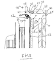
- Fig. 2 indicated at 22 and also in Fig. 3 to recognize the fork frame on the load fork 18 facing side parallel spaced vertical ribs. They serve as impact protection when picking up a pallet. Such a measure is well known.
- FIGS. 1 and 2 shows, 20 two pallet holder 24, 26 are arranged at the top of the fork frame.
- Fig. 1 These hold a Euro-pallet 28, which is placed upright on the fork 18 in abutment with the fork frame 20.
- the structure of the pallet holder 24, 26 is clear from the FIGS. 2 and 3 out. Hereinafter, only the pallet holder 26 will be described in detail.
- the pallet holder 24 is constructed identically.
- the pallet holder 26 has an angle element with a first vertical leg 30 and a second horizontal leg 32.
- the second leg 32 has a rail-like displacement section 34 and a bearing section 36.
- the bearing portion 36 has a hollow profile in which the rail-like portion 34 is slidable. The shift to the right in Fig. 2 away from the fork frame 20 is limited by a pin 38 of the rail portion 34 which is slidable in a slot 40 of the bearing portion 36.
- the bearing portion 36 has a locking knob 42 which is biased by a spring, not shown, and connected to a pin (also not shown) which bears against the rail portion 34 within the bearing portion 36.
- a pin also not shown
- recesses 46 are provided, in which the pin of the knob 42 can engage in order to change the distance of the first leg 30 from the fork frame 20.
- the bearing portion 36 is fixedly connected to a shaft 50 which extends horizontally above the fork frame 20. With the shaft 50 and the bearing portion of the second pallet holder 24 is connected.
- bearing components 52 are connected to the shaft 50 on the top.
- the shaft is biased by a spring 54 such that the spring attempts to rotate the bearing portion 36 in a clockwise direction.
- the spring 54 biases the pallet holder 26 in the in the FIGS. 2 and 3 shown holding position.
- a handle portion 58 is connected at both ends to actuate the pallet holder 26 and 24, respectively.
- a Euro-pallet 50a see also Fig. 1
- two differently sized pallets 60 and 62 kept upright on the load part 12. If only z. B. one of the pallets shown are kept upright, the latching of the rail section 34 is canceled in the bearing section 36 by pressing the button 42 and the rail section 34 can be moved approximately in the direction of the fork frame 20 until a support surface 70 of the first leg 30 a distance to Fork frame 20 has, which corresponds to the height of the recorded range.
- the pallet holder 24, 26 also in the holding position, as in the FIGS. 2 and 3 is shown to lock or lock.
- the spring 54 biases the pallet holder in the holding position, This may be unnecessary.
- a latching is possibly desirable when pivoting the pallet holder 24, 26 in the release position, not shown.
Landscapes
- Engineering & Computer Science (AREA)
- Chemical & Material Sciences (AREA)
- Combustion & Propulsion (AREA)
- Transportation (AREA)
- Mechanical Engineering (AREA)
- Forklifts And Lifting Vehicles (AREA)
Abstract
Flurförderzeug mit einem Antriebsteil und einem Lastteil, das eine Lastgabel und einen Gabelrahmen aufweist sowie mindestens einen Palettenhalter, mit dem eine auf der Lastgabel stehende Palette gesichert wird, wobei der Palettenhalter mindestens ein im Bereich des oberen Endes des Gabelrahmens angeordnetes Halteelement aufweist, das zwischen einer Halteposition, in der es die Palette hintergreift und einer Freigabeposition, in der es die Palette freigibt, bewegbar gelagert ist, wobei das Halteelement außerdem in Richtung der Längsachse des Flurförderzeugs bewegbar gelagert und in unterschiedlichen Längspositionen verriegelbar ist.Truck with a drive part and a load part, which has a fork and a fork frame and at least one pallet holder with which a pallet on the load fork is secured, wherein the pallet holder has at least one arranged in the region of the upper end of the fork frame holding member which between a Holding position in which it engages behind the pallet and a release position in which it releases the pallet, is movably mounted, wherein the holding member is also movably mounted in the direction of the longitudinal axis of the truck and lockable in different longitudinal positions.
Description
Die Erfindung bezieht sich auf ein Flurförderzeug mit einem Palettenhalter nach dem Patentanspruch 1.The invention relates to an industrial truck with a pallet holder according to claim 1.
Aus
Derartige Palettenhalter ermöglichen die Mitnahme einer leeren Palette hochkant am Gabelrücken. Die leere Palettenmitnahme dient dazu, den Fahrzeugschwerpunkt und damit die Fahrstabilität mit einer vollen Palette auf langen Gabeln zu verbessern, da die volle Palette näher an der Hubeinheit aufgenommen werden kann. Auf der zweiten Palette wird kommissioniert, sobald die erste voll ist. Dazu wird die volle Palette auf der Gabel nach vorn geschoben und die Leerpalette nach vorn auf die Lastgabel gekippt.Such pallet holder allow the entrainment of an empty pallet upright on the fork back. The empty pallet take-off is used to improve the vehicle's center of gravity and thus the driving stability with a full range on long forks, since the full range can be accommodated closer to the lifting unit. Picking takes place on the second pallet as soon as the first one is full. To do this, push the full pallet forward on the fork and tilt the empty pallet forward onto the forklift.
Der Erfindung liegt die Aufgabe zugrunde, bei einem Flurförderzeug der eingangs genannten Art den Bedienkomfort zu verbessern und Kommissioniervorgänge zeitlich zu optimieren.The invention has for its object to improve in a truck of the type mentioned the ease of use and to optimize picking times.
Diese Aufgabe wird durch die Merkmale des Anspruchs 1 gelöst.This object is solved by the features of claim 1.
Bei dem erfindungsgemäßen Flurförderzeug ist das Halteelement, das die Palette auf der Lastgabel hochkant hält, in Richtung der Längsachse des Flurförderzeugs bewegbar gelagert und in unterschiedlichen Längspositionen verriegelbar.In the truck according to the invention, the holding element which holds the pallet on the forks upright, movably mounted in the direction of the longitudinal axis of the truck and lockable in different longitudinal positions.
Bei der Erfindung wird davon ausgegangen, dass, etwa im Logistikbereich, unterschiedlich bemaßte Paletten verwendet werden und in einem Lager eine Mischung unterschiedlicher Paletten vorhanden sein kann. Es ist erwünscht, unterschiedlich dimensionierte Paletten mit Hilfe eines Palettenhalters hochkant halten zu können. Diese Möglichkeit ist mit der Erfindung gegeben. Durch die Längsverstellung des Halteelements in Richtung der Längsachse des Flurförderzeugs kann die Aufnahme unterschiedlich hoher Paletten ermöglicht werden oder auch eine Mehrzahl von Paletten. Hierzu muss lediglich eine Längsverstellung des Halteelements vorgenommen werden, um verschiedenartige leere Paletten hochkant am Gabelrücken zu fixieren. Nach einer Ausgestaltung der Erfindung ist das Halteelement in der Freigabeposition verrastbar. Ferner wird bevorzugt eine Federvorspannung für das Halteelement verwendet, welche das Halteelement in die Halteposition vorspannt. Eine Verrastung des Halteelements in der Halteposition kann sich dadurch erübrigen.In the invention, it is assumed that, for example in the logistics sector, differently dimensioned pallets are used and in a warehouse a mixture of different pallets can be present. It is desirable to be able to hold different sized pallets with the help of a pallet holder upright. This possibility is given by the invention. The longitudinal adjustment of the retaining element in the direction of the longitudinal axis of the truck, the recording of different heights of pallets can be made possible or a plurality of pallets. For this purpose, only a longitudinal adjustment of the retaining element must be made in order to fix different types of empty pallets edgewise on the fork back. According to one embodiment of the invention, the retaining element can be latched in the release position. Further, a spring bias is preferably used for the holding element, which biases the holding element in the holding position. A locking of the retaining element in the holding position may be unnecessary.
Bei einer weiteren Ausgestaltung der Erfindung ist das Halteelement ein Winkelelement, dessen erster Schenkel in der Halteposition die Palette hintergreift und dessen zweiter Schenkel um eine horizontale Achse schwenkbar am Gabelrahmen gelagert ist. In der Form ist das Halteelement mit einem Haken vergleichbar, wie er in dem weiter oben angegebenen Dokument offenbart ist.In a further embodiment of the invention, the holding element is an angle element, the first leg engages behind the pallet in the holding position and the second leg is mounted pivotably about a horizontal axis on the fork frame. In the mold, the retaining element is comparable to a hook as disclosed in the document given above.
Es sind nach einer weiteren Ausgestaltung der Erfindung mindestens zwei in Querrichtung des Lastteils beabstandet angeordnete Halteelemente auf einer Welle angebracht, die federvorgespannt am Gabelrahmen gelagert ist. Zur Längsverschiebbarkeit des Halteelements sieht eine weitere Ausgestaltung der Erfindung vor, dass der zweite Schenkel des Winkelelements einen drehbar mit dem Gabelrahmen verbundenen Lagerabschnitt und einen mit dem anderen Schenkel verbundenen Verschiebeabschnitt aufweist, wobei der Verschiebeabschnitt am Lagerabschnitt verschiebbar gelagert und in unterschiedlichen Verschiebestellungen feststellbar ist. Eine Möglichkeit der Feststellbarkeit ist die Verrastung des Verschiebeabschnitts im Lagerabschnitt. Eine andere Möglichkeit besteht in einer weiteren Ausgestaltung der Erfindung darin, dass zwischen Lagerabschnitt und Verschiebeabschnitt eine Klemmschraube wirkt, die Lagerabschnitt und Verschiebeabschnitt in beliebigen Stellungen gegeneinander festklemmt. Hierbei lässt sich der Abstand einer Haltefläche am Halteelement zum Gabelrücken beliebig einstellen. Allerdings erfordert dies eine gewisse Sorgfalt.There are according to a further embodiment of the invention, at least two spaced apart in the transverse direction of the load part arranged holding elements mounted on a shaft which is spring-loaded mounted on the fork frame. For longitudinal displacement of the retaining element provides a further embodiment of the invention, that the second leg of the angle element rotatably connected to the fork frame bearing portion and one with the other leg having connected displacement portion, wherein the displacement portion is slidably mounted on the bearing portion and lockable in different displacement positions. One possibility of the detectability is the locking of the displacement section in the bearing section. Another possibility consists in a further embodiment of the invention is that between the bearing portion and displacement portion acts a clamping screw, the bearing portion and displacement portion clamps in any position against each other. In this case, the distance between a holding surface on the holding element for the fork back can be set arbitrarily. However, this requires a certain care.
Nach einer weiteren Ausgestaltung der Erfindung ist vorgesehen, dass das Halteelement ein Winkelelement ist, dessen erster Schenkel am Gabelrahmen achsparallel verschiebbar gelagert ist und der zweite Schenkel am ersten Schenkel um eine Längsachse des zweiten Schenkels verschwenkbar gelagert ist und sowohl in der Halte- als auch in der Freigabeposition am ersten Schenkel feststellbar ist.According to a further embodiment of the invention it is provided that the holding element is an angle element, the first leg is mounted axially displaceable on the fork frame and the second leg is pivotally mounted on the first leg about a longitudinal axis of the second leg and both in the holding and in the release position on the first leg is detectable.
Eine weitere Ausgestaltung der Erfindung sieht vor, dass Lagerabschnitt und Verschiebeabschnitt ein Querschnittsprofil aufweisen, in dem der Verschiebeabschnitt bzw. der Lagerabschnitt verschiebbar ist.A further embodiment of the invention provides that bearing section and displacement section have a cross-sectional profile in which the displacement section or the bearing section is displaceable.
Eine weitere Ausgestaltung der Erfindung sieht vor, dass am Halteelement bzw. am Lagerabschnitt ein Greifabschnitt angeordnet ist, der zum Verschwenken des Halteelements bzw. des Winkelelementes manuell greifbar ist.A further embodiment of the invention provides that on the holding element or on the bearing portion, a gripping portion is arranged, which is manually gripped for pivoting the holding element or the angle element.
Die erfindungsgemäße Aufgabe wird auch dadurch gelöst, dass Lagerschenkel von zwei oder mehr winkelförmigen Halteelementen im oberen Bereich des Gabelrahmens um eine horizontale Achse schwenkbar gelagert sind, und der andere Schenkel des Winkelelements als Halteschenkel ausgebildet ist, wodurch die Halteelemente in der Halte- bzw. Freigabeposition klappbar sind und die Lagerschenkel der Halteelemente eine unterschiedliche Länge aufweisen. Bei Bedarf wird das jeweilige Halteelement nach vom geklappt, während das andere nach hinten geklappt bleibt. Naturgemäß können auch Paare von unterschiedlich ausgebildeten Halteelementen vorgesehen werden, die passend zur jeweiligen aufgestellten Palette in Form und Länge voneinander abweichen.The object of the invention is also achieved in that bearing legs of two or more angular support members are pivotally mounted about a horizontal axis in the upper region of the fork frame, and the other leg of the angle element is designed as a holding leg, whereby the Retaining elements in the holding or release position can be folded and the bearing legs of the holding elements have a different length. If necessary, the respective holding element is folded to the front, while the other remains folded back. Naturally, it is also possible to provide pairs of differently configured holding elements which differ from one another in terms of shape and length in relation to the respective set-up pallet.
Eine weitere erfindungsgemäße Lösung besteht darin, dass mindestens zwei Halteelemente um eine horizontale, zur Längsachse des Flurförderzeugs parallele Achse am Gabelrahmen schwenkbar gelagert sind, die jeweils eine dem Gabelrahmen zugekehrte Haltefläche aufweisen, wobei die Halteflächen der Halteelemente einen unterschiedlichen Abstand zum Gabelrahmen aufweisen. Je nach Abmessung der hochgestellten Palette wird dasjenige Halteelement in die Halteposition verschwenkt, bei dem der Abstand zwischen der Haltefläche und dem Gabelrahmen der Dimensionierung der Palette entspricht. Nach einer Ausgestaltung der Erfindung hierzu können jeweils zwei Halteelemente als Arme eines doppelarmigen Hebels ausgebildet sein.Another solution according to the invention is that at least two holding elements are pivotally mounted about a horizontal axis parallel to the longitudinal axis of the truck on the fork frame, each having a the fork frame facing holding surface, wherein the holding surfaces of the holding elements have a different distance to the fork frame. Depending on the dimension of the raised pallet, that holding element is pivoted into the holding position, in which the distance between the holding surface and the fork frame corresponds to the dimensioning of the pallet. According to one embodiment of the invention for this purpose, two holding elements may be formed as arms of a double-armed lever.
Ein Ausführungsbeispiel der Erfindung wird nachfolgend anhand von Zeichnungen näher erläutert.
- Fig. 1
- zeigt perspektivisch ein Kommissionier-Flurförderzeug mit Palettenhaltern nach der Erfindung.
- Fig. 2
- zeigt vergrößert einen Teil des Fahrzeugs nach
Fig. 1 mit drei hochkant gehaltenen verschiedenen Paletten. - Fig. 3
- zeigt einen Schnitt durch die Darstellung nach
Fig. 2 entlang der Linie 3-3.
- Fig. 1
- shows in perspective a picking truck with pallet holders according to the invention.
- Fig. 2
- shows enlarged a part of the vehicle after
Fig. 1 with three upright different pallets. - Fig. 3
- shows a section through the illustration
Fig. 2 along the line 3-3.
Das Lastteil 12 ist mit einem rückwärtigen Rahmen 16 an dem Antriebsteil 10 bzw. dem entsprechenden Fahrzeugrahmen befestigt. An einem Gabelrahmen 20 ist eine Lastgabel 18 angebracht mit zwei parallel beabstandeten Gabelarmen, wie an sich bekannt. Ihre Länge ist derart, dass sie zwei Paletten hintereinander aufnehmen kann. An dem Rahmen 16 ist der Gabelrahmen 20 höhenverschiebbar gelagert. Er wird mit Hilfe einer geeigneten Hydraulik betätigt, um wahlweise den sogenannten Freihub auszuführen. Wie in
Beim Hochfahren in den Freihub werden auch Lasträder betätigt, die am vorderen Ende der Gabelarme gelagert sind. Dies ist ebenfalls bekannt und soll nicht weiter erörtert werden.When starting up in the free lift and load wheels are actuated, which are mounted at the front end of the fork arms. This is also known and will not be discussed further.
Wie aus den
Der Aufbau der Palettenhalter 24, 26 geht deutlicher aus den
Wie erkennbar, weist der Palettenhalter 26 ein Winkelelement auf mit einem ersten vertikalen Schenkel 30 und einem zweiten horizontalen Schenkel 32. Der zweite Schenkel 32 weist einen schienenartigen Verschiebeabschnitt 34 und einen Lagerabschnitt 36 auf. Der Lagerabschnitt 36 hat ein Hohlprofil, in dem der schienenartige Abschnitt 34 verschiebbar ist. Die Verschiebung nach rechts in
Der Lagerabschnitt 36 weist einen Feststellknopf 42 auf, der von einer nicht gezeigten Feder vorbelastet und mit einem Stift (ebenfalls nicht gezeigt) verbunden ist, der gegen den Schienenabschnitt 34 innerhalb des Lagerabschnitts 36 anliegt. Im Schienenabschnitt 34 sind Vertiefungen 46 vorgesehen, in welche der Stift des Knopfes 42 einrasten kann, um den Abstand des ersten Schenkels 30 vom Gabelrahmen 20 zu verändern.The bearing
Der Lagerabschnitt 36 ist fest mit einer Welle 50 verbunden, die sich horizontal oberhalb des Gabelrahmens 20 erstreckt. Mit der Welle 50 ist auch der Lagerabschnitt des zweiten Palettenhalters 24 verbunden.The bearing
Mit dem Gabelrahmen 20 sind auf der Oberseite Lagerbauteile 52 für die Welle 50 verbunden. Die Welle ist mit Hilfe einer Feder 54 vorgespannt derart, dass die Feder versucht, den Lagerabschnitt 36 im Uhrzeigersinn zu drehen. Mit anderen Worten, die Feder 54 spannt den Palettenhalter 26 in die in den
Mit der Welle 50 ist an beiden Enden jeweils ein Griffabschnitt 58 verbunden, um den Palettenhalter 26 bzw. 24 zu betätigen. In den
Aus der Beschreibung und den Darstellungen ist ersichtlich, dass in einem Lager verschiedene Paletten vermischt werden können und gleichwohl möglich ist, diese, unabhängig von ihrer Dimensionierung, am Lastteil hochkant festzulegen. Bei der Mitnahme von zwei Paletten werden Wege gespart, da mit dem Fahrzeug eine weitere Palette mitgenommen und kommissioniert werden kann. Nach dem Kommissionieren wird die volle Palette am Lagerplatz abgestellt, während die hintere Palette vorn auf den Gabeln aufgenommen werden kann und die freie Palette am Lastteil heruntergeklappt wird. Dadurch wird der Weg zu einer Palettensammelstation gespart und man kann im Prinzip drei Paletten kommissionieren mit einem Fahrzeug, das für zwei Paletten ausgelegt ist.From the description and the illustrations it can be seen that in a warehouse different pallets can be mixed and nevertheless it is possible to set them upright, regardless of their dimensions, on the load part. When two pallets are taken along, ways are saved, since another pallet can be taken with the vehicle and picked. After picking, the full pallet is stored at the storage area, while the rear pallet can be picked up on the forks and the free pallet is folded down on the load section. This saves the way to a pallet collection station and you can in principle pick three pallets with a vehicle designed for two pallets.
Es sei noch angemerkt, dass es möglich ist, die Palettenhalter 24, 26 auch in der Halteposition, wie sie in den
Claims (14)
dadurch gekennzeichnet, dass
das Halteelement (24, 26) außerdem in Richtung der Längsachse des Flurförderzeugs bewegbar gelagert und in unterschiedlichen Längspositionen verriegelbar ist.Truck with a drive part and a load part, which has a fork and a fork frame and at least one pallet holder with which a pallet on the load fork is secured, wherein the pallet holder has at least one arranged in the region of the upper end of the fork frame holding member which between a Holding position, in which it engages behind the pallet and is movably mounted in a release position, in which it releases the pallet,
characterized in that
the holding element (24, 26) is also movably mounted in the direction of the longitudinal axis of the truck and lockable in different longitudinal positions.
dadurch gekennzeichnet, dass
Lagerschenkel von zwei oder mehr winkelförmigen Halteelementen im oberen Bereich des Gabelrahmens um eine horizontale Achse schwenkbar gelagert sind und der andere Schenkel des Winkelelements als Halteschenkel ausgebildet ist, wodurch die Halteelemente in die Halte- bzw. Freigabeposition klappbar sind und die Lagerschenkel der Halteelemente eine unterschiedliche Länge aufweisen.Truck with a drive part and a load part, which has a fork and a fork frame and at least one pallet holder with which a pallet on the load fork is secured, wherein the pallet holder has at least one arranged in the region of the upper end of the fork frame holding member which between a Holding position, in which it engages behind the pallet and is movably mounted in a release position, in which it releases the pallet,
characterized in that
Bearing leg of two or more angular support members are pivotally mounted about a horizontal axis in the upper region of the fork frame and the other leg of the angle element is designed as a holding leg, whereby the holding elements in the holding or release position can be folded and the bearing legs of the holding elements of a different length exhibit.
dadurch gekennzeichnet, dass
mindestens zwei Halteelemente um eine horizontale, zur Längsachse des Flurförderzeugs parallele Achse am Gabelrahmen schwenkbar gelagert sind, die jeweils eine den Gabelrahmen zugekehrte Haltefläche aufweist, wobei die Halteflächen der Halteelemente einen unterschiedlichen Abstand zum Gabelrahmen aufweisen.Truck with a drive part and a load part, which has a fork and a fork frame and at least one pallet holder with which a standing on the forklift pallet is secured, wherein the pallet holder at least in the region of the upper end of the fork frame arranged holding element which is movably mounted between a holding position in which it engages behind the pallet and a release position in which it releases the pallet,
characterized in that
at least two holding elements about a horizontal, parallel to the longitudinal axis of the truck axis are pivotally mounted on the fork frame, each having a fork frame facing the holding surface, wherein the holding surfaces of the holding elements have a different distance to the fork frame.
Applications Claiming Priority (1)
| Application Number | Priority Date | Filing Date | Title |
|---|---|---|---|
| DE102015113169.2A DE102015113169A1 (en) | 2015-08-10 | 2015-08-10 | Industrial truck with pallet holder |
Publications (2)
| Publication Number | Publication Date |
|---|---|
| EP3130523A1 true EP3130523A1 (en) | 2017-02-15 |
| EP3130523B1 EP3130523B1 (en) | 2018-10-17 |
Family
ID=56615908
Family Applications (1)
| Application Number | Title | Priority Date | Filing Date |
|---|---|---|---|
| EP16183337.1A Active EP3130523B1 (en) | 2015-08-10 | 2016-08-09 | Industrial truck with pallet holder |
Country Status (2)
| Country | Link |
|---|---|
| EP (1) | EP3130523B1 (en) |
| DE (1) | DE102015113169A1 (en) |
Cited By (1)
| Publication number | Priority date | Publication date | Assignee | Title |
|---|---|---|---|---|
| EP3444163A4 (en) * | 2017-05-26 | 2019-03-13 | Miasolé Equipment Integration (Fujian) Co., Ltd | Target carrier |
Families Citing this family (1)
| Publication number | Priority date | Publication date | Assignee | Title |
|---|---|---|---|---|
| DE102017126559A1 (en) * | 2017-11-13 | 2019-05-16 | Jungheinrich Ag | Industrial truck with pallet holder |
Citations (6)
| Publication number | Priority date | Publication date | Assignee | Title |
|---|---|---|---|---|
| US20050104308A1 (en) * | 2003-11-17 | 2005-05-19 | Barnes Bret E. | Secure cargo transporter |
| US20090183953A1 (en) * | 2008-01-22 | 2009-07-23 | Coca-Cola Bottling Co.United, Inc. | Pallet jack system and method for the transportation of stackable packaged goods pallets |
| US7819407B1 (en) * | 2008-06-30 | 2010-10-26 | Marian Charitun | Cart for transporting beach accessories and associated method |
| US8356783B1 (en) * | 2008-09-08 | 2013-01-22 | Greg Gilbertson | Retractable stop assembly for a cart |
| DE102012112428A1 (en) * | 2012-12-17 | 2014-06-18 | Linde Material Handling Gmbh | Industrial truck e.g. picker has locking device that is secured in vertical position and is parked on load receiving unit and manually operable locking unit that is provided between locking position and release position |
| DE102013010656A1 (en) | 2013-06-26 | 2014-12-31 | Jungheinrich Aktiengesellschaft | Industrial truck with a drive part and a load part |
-
2015
- 2015-08-10 DE DE102015113169.2A patent/DE102015113169A1/en not_active Withdrawn
-
2016
- 2016-08-09 EP EP16183337.1A patent/EP3130523B1/en active Active
Patent Citations (6)
| Publication number | Priority date | Publication date | Assignee | Title |
|---|---|---|---|---|
| US20050104308A1 (en) * | 2003-11-17 | 2005-05-19 | Barnes Bret E. | Secure cargo transporter |
| US20090183953A1 (en) * | 2008-01-22 | 2009-07-23 | Coca-Cola Bottling Co.United, Inc. | Pallet jack system and method for the transportation of stackable packaged goods pallets |
| US7819407B1 (en) * | 2008-06-30 | 2010-10-26 | Marian Charitun | Cart for transporting beach accessories and associated method |
| US8356783B1 (en) * | 2008-09-08 | 2013-01-22 | Greg Gilbertson | Retractable stop assembly for a cart |
| DE102012112428A1 (en) * | 2012-12-17 | 2014-06-18 | Linde Material Handling Gmbh | Industrial truck e.g. picker has locking device that is secured in vertical position and is parked on load receiving unit and manually operable locking unit that is provided between locking position and release position |
| DE102013010656A1 (en) | 2013-06-26 | 2014-12-31 | Jungheinrich Aktiengesellschaft | Industrial truck with a drive part and a load part |
Cited By (1)
| Publication number | Priority date | Publication date | Assignee | Title |
|---|---|---|---|---|
| EP3444163A4 (en) * | 2017-05-26 | 2019-03-13 | Miasolé Equipment Integration (Fujian) Co., Ltd | Target carrier |
Also Published As
| Publication number | Publication date |
|---|---|
| DE102015113169A1 (en) | 2017-02-16 |
| EP3130523B1 (en) | 2018-10-17 |
Similar Documents
| Publication | Publication Date | Title |
|---|---|---|
| DE102006007383B4 (en) | Restraint system for a bench in the living area of a mobile home | |
| EP2850968A1 (en) | Piece goods warehouse | |
| EP3581539A1 (en) | Pallet goods lifting device | |
| DE102012001503B4 (en) | Pallet for transporting trolleys | |
| EP3130523B1 (en) | Industrial truck with pallet holder | |
| DE202011000477U1 (en) | transport element | |
| EP2953887B1 (en) | Device for receiving and for transporting loads | |
| DE202010009390U1 (en) | palette | |
| EP2217505B1 (en) | Transport arrangement | |
| WO2017158115A1 (en) | Tilt protection device for a pallet | |
| EP2696008A2 (en) | Telescopic scaffold and method for operating a telescopic scaffold | |
| DE19729124C2 (en) | Fork for forklift trucks | |
| DE102018122634A1 (en) | Load securing system and vehicle comprising such a system and a method for securing loads | |
| DE102008005749B4 (en) | Caddy | |
| DE19931248A1 (en) | Pallet for holding a load, especially a two-wheeler | |
| DE102015215815A1 (en) | Device for handling loads | |
| DE102004053518B4 (en) | Mobilzaunfuß | |
| EP1101706A1 (en) | Articulation for collapsible transport containers | |
| DE19639834C1 (en) | Support stand for inclined positioning of transportable container | |
| EP3483003B1 (en) | Transport device | |
| DE10202983B4 (en) | Transport device for chairs | |
| DE202008010622U1 (en) | Handrail for work platforms and aerial work platforms with a folding mechanism for raising or lowering | |
| DE9112067U1 (en) | Handling device for storage boxes | |
| DE20011002U1 (en) | Cart, especially sack, piercing or stacking cart | |
| DE102021126620A1 (en) | Stackable trolley |
Legal Events
| Date | Code | Title | Description |
|---|---|---|---|
| PUAI | Public reference made under article 153(3) epc to a published international application that has entered the european phase |
Free format text: ORIGINAL CODE: 0009012 |
|
| STAA | Information on the status of an ep patent application or granted ep patent |
Free format text: STATUS: THE APPLICATION HAS BEEN PUBLISHED |
|
| AK | Designated contracting states |
Kind code of ref document: A1 Designated state(s): AL AT BE BG CH CY CZ DE DK EE ES FI FR GB GR HR HU IE IS IT LI LT LU LV MC MK MT NL NO PL PT RO RS SE SI SK SM TR |
|
| AX | Request for extension of the european patent |
Extension state: BA ME |
|
| STAA | Information on the status of an ep patent application or granted ep patent |
Free format text: STATUS: REQUEST FOR EXAMINATION WAS MADE |
|
| 17P | Request for examination filed |
Effective date: 20170724 |
|
| RBV | Designated contracting states (corrected) |
Designated state(s): AL AT BE BG CH CY CZ DE DK EE ES FI FR GB GR HR HU IE IS IT LI LT LU LV MC MK MT NL NO PL PT RO RS SE SI SK SM TR |
|
| GRAP | Despatch of communication of intention to grant a patent |
Free format text: ORIGINAL CODE: EPIDOSNIGR1 |
|
| STAA | Information on the status of an ep patent application or granted ep patent |
Free format text: STATUS: GRANT OF PATENT IS INTENDED |
|
| RIC1 | Information provided on ipc code assigned before grant |
Ipc: B62B 3/06 20060101AFI20180228BHEP |
|
| INTG | Intention to grant announced |
Effective date: 20180322 |
|
| GRAS | Grant fee paid |
Free format text: ORIGINAL CODE: EPIDOSNIGR3 |
|
| GRAA | (expected) grant |
Free format text: ORIGINAL CODE: 0009210 |
|
| STAA | Information on the status of an ep patent application or granted ep patent |
Free format text: STATUS: THE PATENT HAS BEEN GRANTED |
|
| AK | Designated contracting states |
Kind code of ref document: B1 Designated state(s): AL AT BE BG CH CY CZ DE DK EE ES FI FR GB GR HR HU IE IS IT LI LT LU LV MC MK MT NL NO PL PT RO RS SE SI SK SM TR |
|
| REG | Reference to a national code |
Ref country code: GB Ref legal event code: FG4D Free format text: NOT ENGLISH |
|
| REG | Reference to a national code |
Ref country code: CH Ref legal event code: EP |
|
| REG | Reference to a national code |
Ref country code: IE Ref legal event code: FG4D Free format text: LANGUAGE OF EP DOCUMENT: GERMAN |
|
| REG | Reference to a national code |
Ref country code: DE Ref legal event code: R096 Ref document number: 502016002236 Country of ref document: DE Ref country code: AT Ref legal event code: REF Ref document number: 1053640 Country of ref document: AT Kind code of ref document: T Effective date: 20181115 |
|
| REG | Reference to a national code |
Ref country code: NL Ref legal event code: MP Effective date: 20181017 |
|
| REG | Reference to a national code |
Ref country code: LT Ref legal event code: MG4D |
|
| PG25 | Lapsed in a contracting state [announced via postgrant information from national office to epo] |
Ref country code: NL Free format text: LAPSE BECAUSE OF FAILURE TO SUBMIT A TRANSLATION OF THE DESCRIPTION OR TO PAY THE FEE WITHIN THE PRESCRIBED TIME-LIMIT Effective date: 20181017 |
|
| PG25 | Lapsed in a contracting state [announced via postgrant information from national office to epo] |
Ref country code: ES Free format text: LAPSE BECAUSE OF FAILURE TO SUBMIT A TRANSLATION OF THE DESCRIPTION OR TO PAY THE FEE WITHIN THE PRESCRIBED TIME-LIMIT Effective date: 20181017 Ref country code: FI Free format text: LAPSE BECAUSE OF FAILURE TO SUBMIT A TRANSLATION OF THE DESCRIPTION OR TO PAY THE FEE WITHIN THE PRESCRIBED TIME-LIMIT Effective date: 20181017 Ref country code: LV Free format text: LAPSE BECAUSE OF FAILURE TO SUBMIT A TRANSLATION OF THE DESCRIPTION OR TO PAY THE FEE WITHIN THE PRESCRIBED TIME-LIMIT Effective date: 20181017 Ref country code: PL Free format text: LAPSE BECAUSE OF FAILURE TO SUBMIT A TRANSLATION OF THE DESCRIPTION OR TO PAY THE FEE WITHIN THE PRESCRIBED TIME-LIMIT Effective date: 20181017 Ref country code: NO Free format text: LAPSE BECAUSE OF FAILURE TO SUBMIT A TRANSLATION OF THE DESCRIPTION OR TO PAY THE FEE WITHIN THE PRESCRIBED TIME-LIMIT Effective date: 20190117 Ref country code: LT Free format text: LAPSE BECAUSE OF FAILURE TO SUBMIT A TRANSLATION OF THE DESCRIPTION OR TO PAY THE FEE WITHIN THE PRESCRIBED TIME-LIMIT Effective date: 20181017 Ref country code: HR Free format text: LAPSE BECAUSE OF FAILURE TO SUBMIT A TRANSLATION OF THE DESCRIPTION OR TO PAY THE FEE WITHIN THE PRESCRIBED TIME-LIMIT Effective date: 20181017 Ref country code: BG Free format text: LAPSE BECAUSE OF FAILURE TO SUBMIT A TRANSLATION OF THE DESCRIPTION OR TO PAY THE FEE WITHIN THE PRESCRIBED TIME-LIMIT Effective date: 20190117 Ref country code: IS Free format text: LAPSE BECAUSE OF FAILURE TO SUBMIT A TRANSLATION OF THE DESCRIPTION OR TO PAY THE FEE WITHIN THE PRESCRIBED TIME-LIMIT Effective date: 20190217 |
|
| PG25 | Lapsed in a contracting state [announced via postgrant information from national office to epo] |
Ref country code: RS Free format text: LAPSE BECAUSE OF FAILURE TO SUBMIT A TRANSLATION OF THE DESCRIPTION OR TO PAY THE FEE WITHIN THE PRESCRIBED TIME-LIMIT Effective date: 20181017 Ref country code: PT Free format text: LAPSE BECAUSE OF FAILURE TO SUBMIT A TRANSLATION OF THE DESCRIPTION OR TO PAY THE FEE WITHIN THE PRESCRIBED TIME-LIMIT Effective date: 20190217 Ref country code: GR Free format text: LAPSE BECAUSE OF FAILURE TO SUBMIT A TRANSLATION OF THE DESCRIPTION OR TO PAY THE FEE WITHIN THE PRESCRIBED TIME-LIMIT Effective date: 20190118 Ref country code: AL Free format text: LAPSE BECAUSE OF FAILURE TO SUBMIT A TRANSLATION OF THE DESCRIPTION OR TO PAY THE FEE WITHIN THE PRESCRIBED TIME-LIMIT Effective date: 20181017 Ref country code: SE Free format text: LAPSE BECAUSE OF FAILURE TO SUBMIT A TRANSLATION OF THE DESCRIPTION OR TO PAY THE FEE WITHIN THE PRESCRIBED TIME-LIMIT Effective date: 20181017 |
|
| REG | Reference to a national code |
Ref country code: DE Ref legal event code: R097 Ref document number: 502016002236 Country of ref document: DE |
|
| PG25 | Lapsed in a contracting state [announced via postgrant information from national office to epo] |
Ref country code: IT Free format text: LAPSE BECAUSE OF FAILURE TO SUBMIT A TRANSLATION OF THE DESCRIPTION OR TO PAY THE FEE WITHIN THE PRESCRIBED TIME-LIMIT Effective date: 20181017 Ref country code: CZ Free format text: LAPSE BECAUSE OF FAILURE TO SUBMIT A TRANSLATION OF THE DESCRIPTION OR TO PAY THE FEE WITHIN THE PRESCRIBED TIME-LIMIT Effective date: 20181017 Ref country code: DK Free format text: LAPSE BECAUSE OF FAILURE TO SUBMIT A TRANSLATION OF THE DESCRIPTION OR TO PAY THE FEE WITHIN THE PRESCRIBED TIME-LIMIT Effective date: 20181017 |
|
| PLBE | No opposition filed within time limit |
Free format text: ORIGINAL CODE: 0009261 |
|
| STAA | Information on the status of an ep patent application or granted ep patent |
Free format text: STATUS: NO OPPOSITION FILED WITHIN TIME LIMIT |
|
| PG25 | Lapsed in a contracting state [announced via postgrant information from national office to epo] |
Ref country code: SM Free format text: LAPSE BECAUSE OF FAILURE TO SUBMIT A TRANSLATION OF THE DESCRIPTION OR TO PAY THE FEE WITHIN THE PRESCRIBED TIME-LIMIT Effective date: 20181017 Ref country code: EE Free format text: LAPSE BECAUSE OF FAILURE TO SUBMIT A TRANSLATION OF THE DESCRIPTION OR TO PAY THE FEE WITHIN THE PRESCRIBED TIME-LIMIT Effective date: 20181017 Ref country code: SK Free format text: LAPSE BECAUSE OF FAILURE TO SUBMIT A TRANSLATION OF THE DESCRIPTION OR TO PAY THE FEE WITHIN THE PRESCRIBED TIME-LIMIT Effective date: 20181017 Ref country code: RO Free format text: LAPSE BECAUSE OF FAILURE TO SUBMIT A TRANSLATION OF THE DESCRIPTION OR TO PAY THE FEE WITHIN THE PRESCRIBED TIME-LIMIT Effective date: 20181017 |
|
| 26N | No opposition filed |
Effective date: 20190718 |
|
| PG25 | Lapsed in a contracting state [announced via postgrant information from national office to epo] |
Ref country code: SI Free format text: LAPSE BECAUSE OF FAILURE TO SUBMIT A TRANSLATION OF THE DESCRIPTION OR TO PAY THE FEE WITHIN THE PRESCRIBED TIME-LIMIT Effective date: 20181017 |
|
| PG25 | Lapsed in a contracting state [announced via postgrant information from national office to epo] |
Ref country code: TR Free format text: LAPSE BECAUSE OF FAILURE TO SUBMIT A TRANSLATION OF THE DESCRIPTION OR TO PAY THE FEE WITHIN THE PRESCRIBED TIME-LIMIT Effective date: 20181017 |
|
| PG25 | Lapsed in a contracting state [announced via postgrant information from national office to epo] |
Ref country code: LU Free format text: LAPSE BECAUSE OF NON-PAYMENT OF DUE FEES Effective date: 20190809 Ref country code: MC Free format text: LAPSE BECAUSE OF FAILURE TO SUBMIT A TRANSLATION OF THE DESCRIPTION OR TO PAY THE FEE WITHIN THE PRESCRIBED TIME-LIMIT Effective date: 20181017 Ref country code: LI Free format text: LAPSE BECAUSE OF NON-PAYMENT OF DUE FEES Effective date: 20190831 Ref country code: CH Free format text: LAPSE BECAUSE OF NON-PAYMENT OF DUE FEES Effective date: 20190831 |
|
| REG | Reference to a national code |
Ref country code: BE Ref legal event code: MM Effective date: 20190831 |
|
| PG25 | Lapsed in a contracting state [announced via postgrant information from national office to epo] |
Ref country code: IE Free format text: LAPSE BECAUSE OF NON-PAYMENT OF DUE FEES Effective date: 20190809 |
|
| PG25 | Lapsed in a contracting state [announced via postgrant information from national office to epo] |
Ref country code: BE Free format text: LAPSE BECAUSE OF NON-PAYMENT OF DUE FEES Effective date: 20190831 |
|
| PG25 | Lapsed in a contracting state [announced via postgrant information from national office to epo] |
Ref country code: CY Free format text: LAPSE BECAUSE OF FAILURE TO SUBMIT A TRANSLATION OF THE DESCRIPTION OR TO PAY THE FEE WITHIN THE PRESCRIBED TIME-LIMIT Effective date: 20181017 |
|
| PG25 | Lapsed in a contracting state [announced via postgrant information from national office to epo] |
Ref country code: MT Free format text: LAPSE BECAUSE OF FAILURE TO SUBMIT A TRANSLATION OF THE DESCRIPTION OR TO PAY THE FEE WITHIN THE PRESCRIBED TIME-LIMIT Effective date: 20181017 Ref country code: HU Free format text: LAPSE BECAUSE OF FAILURE TO SUBMIT A TRANSLATION OF THE DESCRIPTION OR TO PAY THE FEE WITHIN THE PRESCRIBED TIME-LIMIT; INVALID AB INITIO Effective date: 20160809 |
|
| PG25 | Lapsed in a contracting state [announced via postgrant information from national office to epo] |
Ref country code: MK Free format text: LAPSE BECAUSE OF FAILURE TO SUBMIT A TRANSLATION OF THE DESCRIPTION OR TO PAY THE FEE WITHIN THE PRESCRIBED TIME-LIMIT Effective date: 20181017 |
|
| REG | Reference to a national code |
Ref country code: AT Ref legal event code: MM01 Ref document number: 1053640 Country of ref document: AT Kind code of ref document: T Effective date: 20210809 |
|
| PG25 | Lapsed in a contracting state [announced via postgrant information from national office to epo] |
Ref country code: AT Free format text: LAPSE BECAUSE OF NON-PAYMENT OF DUE FEES Effective date: 20210809 |
|
| P01 | Opt-out of the competence of the unified patent court (upc) registered |
Effective date: 20230628 |
|
| PGFP | Annual fee paid to national office [announced via postgrant information from national office to epo] |
Ref country code: GB Payment date: 20230824 Year of fee payment: 8 |
|
| PGFP | Annual fee paid to national office [announced via postgrant information from national office to epo] |
Ref country code: FR Payment date: 20230821 Year of fee payment: 8 Ref country code: DE Payment date: 20230822 Year of fee payment: 8 |