EP3128821B1 - Electronic device - Google Patents
Electronic device Download PDFInfo
- Publication number
- EP3128821B1 EP3128821B1 EP15773955.8A EP15773955A EP3128821B1 EP 3128821 B1 EP3128821 B1 EP 3128821B1 EP 15773955 A EP15773955 A EP 15773955A EP 3128821 B1 EP3128821 B1 EP 3128821B1
- Authority
- EP
- European Patent Office
- Prior art keywords
- display unit
- pair
- end portion
- main slider
- slider
- Prior art date
- Legal status (The legal status is an assumption and is not a legal conclusion. Google has not performed a legal analysis and makes no representation as to the accuracy of the status listed.)
- Active
Links
Images




Classifications
-
- G—PHYSICS
- G01—MEASURING; TESTING
- G01C—MEASURING DISTANCES, LEVELS OR BEARINGS; SURVEYING; NAVIGATION; GYROSCOPIC INSTRUMENTS; PHOTOGRAMMETRY OR VIDEOGRAMMETRY
- G01C21/00—Navigation; Navigational instruments not provided for in groups G01C1/00 - G01C19/00
- G01C21/26—Navigation; Navigational instruments not provided for in groups G01C1/00 - G01C19/00 specially adapted for navigation in a road network
- G01C21/265—Navigation; Navigational instruments not provided for in groups G01C1/00 - G01C19/00 specially adapted for navigation in a road network constructional aspects of navigation devices, e.g. housings, mountings, displays
-
- B—PERFORMING OPERATIONS; TRANSPORTING
- B60—VEHICLES IN GENERAL
- B60K—ARRANGEMENT OR MOUNTING OF PROPULSION UNITS OR OF TRANSMISSIONS IN VEHICLES; ARRANGEMENT OR MOUNTING OF PLURAL DIVERSE PRIME-MOVERS IN VEHICLES; AUXILIARY DRIVES FOR VEHICLES; INSTRUMENTATION OR DASHBOARDS FOR VEHICLES; ARRANGEMENTS IN CONNECTION WITH COOLING, AIR INTAKE, GAS EXHAUST OR FUEL SUPPLY OF PROPULSION UNITS IN VEHICLES
- B60K35/00—Instruments specially adapted for vehicles; Arrangement of instruments in or on vehicles
- B60K35/20—Output arrangements, i.e. from vehicle to user, associated with vehicle functions or specially adapted therefor
- B60K35/21—Output arrangements, i.e. from vehicle to user, associated with vehicle functions or specially adapted therefor using visual output, e.g. blinking lights or matrix displays
- B60K35/22—Display screens
-
- B—PERFORMING OPERATIONS; TRANSPORTING
- B60—VEHICLES IN GENERAL
- B60K—ARRANGEMENT OR MOUNTING OF PROPULSION UNITS OR OF TRANSMISSIONS IN VEHICLES; ARRANGEMENT OR MOUNTING OF PLURAL DIVERSE PRIME-MOVERS IN VEHICLES; AUXILIARY DRIVES FOR VEHICLES; INSTRUMENTATION OR DASHBOARDS FOR VEHICLES; ARRANGEMENTS IN CONNECTION WITH COOLING, AIR INTAKE, GAS EXHAUST OR FUEL SUPPLY OF PROPULSION UNITS IN VEHICLES
- B60K35/00—Instruments specially adapted for vehicles; Arrangement of instruments in or on vehicles
- B60K35/20—Output arrangements, i.e. from vehicle to user, associated with vehicle functions or specially adapted therefor
- B60K35/21—Output arrangements, i.e. from vehicle to user, associated with vehicle functions or specially adapted therefor using visual output, e.g. blinking lights or matrix displays
- B60K35/22—Display screens
- B60K35/223—Flexible displays
-
- B—PERFORMING OPERATIONS; TRANSPORTING
- B60—VEHICLES IN GENERAL
- B60K—ARRANGEMENT OR MOUNTING OF PROPULSION UNITS OR OF TRANSMISSIONS IN VEHICLES; ARRANGEMENT OR MOUNTING OF PLURAL DIVERSE PRIME-MOVERS IN VEHICLES; AUXILIARY DRIVES FOR VEHICLES; INSTRUMENTATION OR DASHBOARDS FOR VEHICLES; ARRANGEMENTS IN CONNECTION WITH COOLING, AIR INTAKE, GAS EXHAUST OR FUEL SUPPLY OF PROPULSION UNITS IN VEHICLES
- B60K35/00—Instruments specially adapted for vehicles; Arrangement of instruments in or on vehicles
- B60K35/50—Instruments characterised by their means of attachment to or integration in the vehicle
- B60K35/53—Movable instruments, e.g. slidable
-
- B—PERFORMING OPERATIONS; TRANSPORTING
- B60—VEHICLES IN GENERAL
- B60K—ARRANGEMENT OR MOUNTING OF PROPULSION UNITS OR OF TRANSMISSIONS IN VEHICLES; ARRANGEMENT OR MOUNTING OF PLURAL DIVERSE PRIME-MOVERS IN VEHICLES; AUXILIARY DRIVES FOR VEHICLES; INSTRUMENTATION OR DASHBOARDS FOR VEHICLES; ARRANGEMENTS IN CONNECTION WITH COOLING, AIR INTAKE, GAS EXHAUST OR FUEL SUPPLY OF PROPULSION UNITS IN VEHICLES
- B60K2360/00—Indexing scheme associated with groups B60K35/00 or B60K37/00 relating to details of instruments or dashboards
- B60K2360/143—Touch sensitive instrument input devices
- B60K2360/1438—Touch screens
- B60K2360/1442—Emulation of input devices
-
- B—PERFORMING OPERATIONS; TRANSPORTING
- B60—VEHICLES IN GENERAL
- B60K—ARRANGEMENT OR MOUNTING OF PROPULSION UNITS OR OF TRANSMISSIONS IN VEHICLES; ARRANGEMENT OR MOUNTING OF PLURAL DIVERSE PRIME-MOVERS IN VEHICLES; AUXILIARY DRIVES FOR VEHICLES; INSTRUMENTATION OR DASHBOARDS FOR VEHICLES; ARRANGEMENTS IN CONNECTION WITH COOLING, AIR INTAKE, GAS EXHAUST OR FUEL SUPPLY OF PROPULSION UNITS IN VEHICLES
- B60K2360/00—Indexing scheme associated with groups B60K35/00 or B60K37/00 relating to details of instruments or dashboards
- B60K2360/145—Instrument input by combination of touch screen and hardware input devices
-
- B—PERFORMING OPERATIONS; TRANSPORTING
- B60—VEHICLES IN GENERAL
- B60K—ARRANGEMENT OR MOUNTING OF PROPULSION UNITS OR OF TRANSMISSIONS IN VEHICLES; ARRANGEMENT OR MOUNTING OF PLURAL DIVERSE PRIME-MOVERS IN VEHICLES; AUXILIARY DRIVES FOR VEHICLES; INSTRUMENTATION OR DASHBOARDS FOR VEHICLES; ARRANGEMENTS IN CONNECTION WITH COOLING, AIR INTAKE, GAS EXHAUST OR FUEL SUPPLY OF PROPULSION UNITS IN VEHICLES
- B60K35/00—Instruments specially adapted for vehicles; Arrangement of instruments in or on vehicles
- B60K35/10—Input arrangements, i.e. from user to vehicle, associated with vehicle functions or specially adapted therefor
-
- B—PERFORMING OPERATIONS; TRANSPORTING
- B60—VEHICLES IN GENERAL
- B60K—ARRANGEMENT OR MOUNTING OF PROPULSION UNITS OR OF TRANSMISSIONS IN VEHICLES; ARRANGEMENT OR MOUNTING OF PLURAL DIVERSE PRIME-MOVERS IN VEHICLES; AUXILIARY DRIVES FOR VEHICLES; INSTRUMENTATION OR DASHBOARDS FOR VEHICLES; ARRANGEMENTS IN CONNECTION WITH COOLING, AIR INTAKE, GAS EXHAUST OR FUEL SUPPLY OF PROPULSION UNITS IN VEHICLES
- B60K35/00—Instruments specially adapted for vehicles; Arrangement of instruments in or on vehicles
- B60K35/20—Output arrangements, i.e. from vehicle to user, associated with vehicle functions or specially adapted therefor
- B60K35/25—Output arrangements, i.e. from vehicle to user, associated with vehicle functions or specially adapted therefor using haptic output
Definitions
- the present invention relates to an electronic device including a main body having a fixing surface and a display unit capable of taking an inclined posture relative to the fixing surface.
- the navigation device includes a main body having a fixing surface in which a medium insertion opening is formed and a display unit having a display surface for displaying information.
- the display unit can take a fixed state in which the display unit is fixed to the fixing surface and an inclined state in which the display unit takes an inclined posture relative to the fixing surface.
- the medium insertion opening is exposed, so that a medium can be inserted or discharged.
- the display unit is in the fixed state
- the medium insertion opening is covered by the display unit.
- the display unit takes a posture parallel with the fixing surface.
- a transition operation of the display unit from the fixed state to the inclined state is also referred to as a tilt operation.
- Patent Literature 1 discloses an electronic device having a mechanism configured to enable the tilt operation.
- a display unit of the display device disclosed in Patent Literature 1 is supported by a plurality of arms.
- the display unit is configured to be rotatable about a support point of each arm.
- the electronic device disclosed in Patent Literature 1 has a movement part and a motor.
- the movement part is configured to be moveable in a front-back direction with respect to a main body by an operation of the motor.
- a front end portion of the movement part is fixed to one of the plurality of arms. As the movement part moves forwards, the display unit transitions to the inclined state.
- JP 2004 210191 A discloses a front panel device in which a long hole formed in a slide member is inserted in a cylindrical body erected from a bottom face of a chassis, the slide member is reciprocated in the longitudinal direction of the chassis with the cylindrical body and the long hole as guide means, and a movable nose connected to a tip of the slide member is turned thereby, a synthetic resin spacer and a leaf spring are successively placed on the slide member, and both ends of the leaf spring are fixed to a shaft part of a pair of cylindrical bodies protruded from the longitudinal holes by screws.
- the leaf spring is pressed against a thick-walled portion formed on the spacer between the screws, and deflected in a curved shape.
- Patent Literature 1 JP-A-2005-116620
- the movement part moves forwards and thus the display panel transitions to the inclined state
- an abnormal sound may be caused to each member of the electronic device.
- the movement part moves forwards, so that the moment of the arm increases.
- the arm is configured to support the display panel having a predetermined weight.
- an electronic device according to claim 1.
- the bending of the first movement part which is caused due to the vibrations to be transmitted from the fixing target, is suppressed, so that it is possible to suppress an abnormal sound from each member upon change in posture of the display unit and in the inclined state. Also, the stability of a posture change operation of the display unit is improved.
- the electronic device can be configured as follows.
- the first movement part is configured to further move forwards by a second distance after the first movement part is contacted to the support part until the display unit reaches the inclined state.
- the rigidity of the first movement part against the vibrations transmitted to be from the fixing target is further increased. Therefore, the bending of the first movement part is further suppressed, so that it is possible to further suppress the abnormal sound from each member upon change in posture of the display unit and in the inclined state.
- the electronic device can be configured as follows.
- the support part has a bent shape so as to form a corner part convex towards the first movement part, and the corner part is in contact with the first movement part.
- the bending of the first movement part is immediately suppressed after the display unit starts to transition to the inclined state. Therefore, it is possible to further suppress the abnormal sound from each member upon change in posture of the display unit and in the inclined state.
- the electronic device can be configured as follows.
- the first movement part has a sliding path extending in a direction of the reciprocal movement
- the coupling pin since the coupling pin is engaged with the rear end portion of the sliding path in the inclined state of the display unit, even though the vibrations are transmitted from the fixing target, it is possible to suppress displacement and deformation of the first movement part and shaking of the display unit. Therefore, it is possible to further suppress the abnormal sound from each member upon change in posture of the display unit and in the inclined state. Also, the stability of the posture change operation of the display unit is secured.
- FIG. 1 depicts an outward appearance of an electronic device 10 according to an illustrative embodiment.
- the electronic device 10 is a device that is to be mounted on a vehicle such as an automobile and is to be used in a vehicle interior.
- the electronic device 10 has a navigation function of guiding a route to a destination and an audio function of outputting voice into the vehicle interior.
- a three dimensional Cartesian coordinate system shown in the drawings is used to appropriately indicate directions and orientations.
- the Cartesian coordinate system is relatively fixed to a main body 1.
- An X-axis direction corresponds to a left-right direction
- a Y-axis direction corresponds to a front-back direction
- a Z-axis direction corresponds to an upper-lower direction.
- a +X-side is a left side of a display surface of a display panel 2
- a -X-side is a right side of the display surface.
- a +Y-side is a front side of the display surface
- a - Y-side is a backside of the display surface.
- a +Z-side is an upper side and a -Z-side is a lower side.
- the electronic device 10 has a main body 1, a display panel 2 and a front panel 5.
- the main body 1 has a chassis 11.
- a plurality of components for implementing a variety of functions of the electronic device 10 is accommodated.
- the display panel 2 has a display 3 (an example of the display surface) such as a liquid crystal monitor.
- the display surface of the display panel 2 has a substantially rectangular shape having a longitudinal direction and a width direction.
- the display panel 2 functions as the display unit of the electronic device 10.
- the display 3 has a touch panel.
- the display 3 is configured to receive a user's operation.
- the user can input a variety of instructions into the electronic device 10 by touching command buttons displayed on the display 3.
- the main body 1 is configured to execute diverse processing, in response to the user's operation performed on the display panel 2.
- the display panel 2 may have a physical operation button with which the user inputs an instruction.
- the front panel 5 (an example of the fixing surface) is provided at a front part of the main body 1. As shown in FIG. 2 , the front panel 5 has a disc insertion opening 4. When the display panel 2 is in a fixed state, the disc insertion opening 4 is covered by the display panel 2.
- the display panel 2 is provided in front of (the +Y direction) the front panel 5.
- the display panel 2 covers the substantially entire surface (front surface) of the front panel 5.
- the disc insertion opening 4 is covered by the display panel 2.
- the electronic device 10 has a motor 21, a plurality of gears 22 and a main slider 31.
- the motor 21, the plurality of gears 22 and the main slider 31 are provided on a bottom of the chassis 11.
- the motor 21 is configured to generate a driving force.
- the plurality of gears 22 is configured to transmit the driving force of the motor 21 to the main slider 31.
- the main slider 31 (an example of the first movement part) has a pair of left and right (the X-axis direction) sliding members 301 and a coupling member 311.
- the pair of sliding members 301 extends in the front-back direction (the Y-axis direction) of the chassis 11. Both sides of the chassis 11 are provided with a pair of guide rails 33. Each sliding member 301 is engaged with the corresponding guide rail 33 and is kept to freely slide in the front-back direction (the Y-axis direction) of the chassis 11.
- the coupling member 311 extends in the left-right direction (the X-axis direction) of the chassis 11 and is configured to couple front end portions of the pair of sliding members 301.
- the main slider 31 is configured to slide in the front-back direction (the Y-axis direction), which is a direction intersecting with the front panel 5, by the driving force generated from the motor 21.
- Each sliding member 301 is formed with a pin sliding path 101.
- the pin sliding path 101 is a long hole extending in the front-back direction (the Y-axis direction) of the chassis 11.
- a pair of guide paths 102 is formed at a front part of a bottom surface of the chassis 11.
- a front end portion of each pin sliding path 101 overlaps with a rear end portion of the corresponding guide path 102, as seen from the Z-axis direction.
- the electronic device 10 has a pair of coupling pins 51. Each coupling pin 51 is inserted into the corresponding pin sliding path 101 and the corresponding guide path 102.
- Each coupling pin 51 has a barrel cylinder having a flange (not shown) inserted into the part at which the pin sliding path 101 and the guide path 102 overlap each other, a friction ring fitted to the barrel cylinder and a screw screwed to the barrel cylinder.
- the electronic device 10 has a sub-slider 32 (an example of the second movement part).
- the sub-slider 32 has a pair of sliding members 302 and a connection member 312.
- the pair of sliding members 302 extends in the front-back direction (the Y-axis direction) of the chassis 11.
- Each sliding member 302 is engaged with the corresponding guide rail 33 and is kept to freely slide in the front-back direction (the Y-axis direction) of the chassis 11.
- the connection member 312 extends in the left-right direction (the X-axis direction) of the chassis 11, and is configured to couple front end portions of the pair of sliding members 302.
- Each coupling pin 51 is inserted into a predetermined part of the corresponding sliding member 302 in the upper-lower direction (the Z-axis direction).
- a pair of plate springs 52 which are elastic members, is provided in the vicinity of left and right sides (the X-axis direction) of the chassis 11. As shown in FIG. 4 , each plate spring 52 is in contact with the corresponding sliding member 302 of the sub-slider 32. Each plate spring 52 is configured to press the corresponding sliding member 302 towards the corresponding sliding member 301 of the main slider 31.
- the display panel 2 has a pair of shafts 401 and a pair of shafts 402.
- the pair of shafts 401 is provided at substantially central portions in the upper-lower direction of left and right sides of the display panel 2.
- the pair of shafts 402 is provided at lower portions in the upper-lower direction of left and right sides of the display panel 2.
- the sub-slider 32 has a pair of shafts 403. Also, the front end portion of each sliding member 302 of the sub-slider 32 forms an arm part 43.
- Each shaft 403 is provided at the corresponding arm part 43.
- each motion link 41 is a member having a first part LP and a second part SP.
- the first part LP is longer than the second part SP.
- the first part LP and the second part SP extend in intersecting directions and form a bent part CL.
- each of the first parts LP extends in the upper-lower direction and each of the second parts SP extends in the front-back direction.
- Each of the first parts LP is rotatably connected to the corresponding shaft 401 (which is an example of the second connection part).
- Each of the second parts SP is rotatably connected to the corresponding shaft 403 (which is an example of the third connection part).
- each sliding member 301 of the main slider 31 forms an arm part 42.
- Each arm part 42 is rotatably connected to the corresponding shaft 402 (which is an example of the first connection part).
- the display panel 2 is configured to be rotatable relative to each arm part 42 about the corresponding shaft 402.
- each sliding member 301 is engaged with the corresponding guide rail 33 provided for the chassis 11, and is kept to freely slide in the front-back direction (the Y-axis direction).
- each guide rail 33 has a plurality of convex portions. The plurality of convex portions is arranged at different positions in the front-back direction (the Y-axis direction).
- the plurality of convex portions is arranged at positions facing the sliding member 301.
- the plurality of convex portions is kept to sandwich the sliding member 301 in the upper-lower direction.
- Each sliding member 302 of the sub-slider 32 is provided on the corresponding guide rail 33.
- an instruction signal for operating the display panel 2 is output.
- the motor 21 starts an operation in response to the instruction signal, and drives the plurality of gears 22.
- the plurality of gears 22 is driven, so that the sliding member 301 engaged with one of the plurality of gears 22 is moved forwards (the +Y direction), as shown in FIGS. 5 and 7 . That is, the main slider 31 is moved forwards.
- each coupling pin 51 engaged with the front end portion of each pin sliding path 101 is moved forwards (the +Y direction) along each guide path 102 from the rear end portion thereof.
- the corresponding sliding member 302 of the sub-slider 32 also starts to move forwards. That is, as the main slider 31 is moved, the sub-slider 32 is moved in the same direction as the main slider 31.
- each sliding member 302 of the sub-slider 32 As each sliding member 302 of the sub-slider 32 is moved, the corresponding motion link 41 supported to the shaft 403 provided for each arm part 43 also starts to move forwards. Also, since the arm part 42 of each sliding member 301 also starts to move forwards, the display panel 2 is moved forwards. At this time, since each arm part 42 is moved forwards earlier than the motion link 41, the display panel 2 is moved with an inclined posture where the upper end thereof is located slightly posterior to the lower end thereof.
- each coupling pin 51 reaches the front end portion of the corresponding guide path 102 and stops, as shown in FIG. 6 .
- the corresponding sliding member 301 continues to move forwards. In other words, each coupling pin 51 moves towards the rear end along the corresponding pin sliding path 101, so that it moves rearwards relative to the corresponding sliding member 301.
- the arm part 42 of the sliding member 301 continues to move forwards (the +Y direction), so that the lower end of the display panel 2 moves forwards, as shown in FIG. 8 .
- the display panel 2 is tilted so that the front surface (the display surface) thereof faces upwards obliquely.
- the upper end of the display panel 2 is spaced forwards from the surface (front surface) of the front panel 5, as shown in FIG. 7 . For this reason, when the display panel 2 transitions to the inclined state, the display panel 2 is not contacted to the surface of the front panel 5.
- each motion link 41 is contacted to the main slider 31, as shown in FIG. 9 .
- a corner part CP (a part shown with a black square) of each motion link 41 is contacted to the corresponding sliding member 301.
- the bent part CL of the motion link 41 forms a corner part that is convex towards the corresponding sliding member 301.
- the corner part CP corresponds to the corner part.
- each coupling pin 51 is positioned between the front end portion and the rear end portion of the corresponding pin sliding path 101.
- each sliding member 301 is moved by a first distance, which is the predetermined distance, towards the front (the +Y direction) shown with an arrow AR1 in FIG. 9 , so that the display panel 2 is rotated in a clockwise direction (as seen from a right side) shown with an arrow AR2 about the respective shafts 401, 402 serving as the rotary shafts.
- a first distance which is the predetermined distance
- the display panel 2 is rotated in a clockwise direction (as seen from a right side) shown with an arrow AR2 about the respective shafts 401, 402 serving as the rotary shafts.
- each motion link 41 is rotated in a counterclockwise direction (as seen from a right side) about the corresponding shaft 403.
- each motion link 41 and the corresponding sliding member 301 are contacted to each other, and a downward (vertical direction) force (bias) shown with an arrow AR3 is applied to the contact part thereof.
- the first distance by which each sliding member 301 moves is about 10 cm on the basis of the position of the member 301 in the fixed state of the display panel 2, for example.
- the parts of the plurality of convex portions provided for the respective guide rails 33, which are contacted to the corresponding sliding member 301, are denoted as contact parts TP1, TP2 shown with black circles.
- a contact part between the contact part TP1 and the sliding member 301 is denoted as a first support point, and a distance from the first support point to the shaft 402 is denoted as a distance L1.
- a contact part between the contact part TP2 and the sliding member 301 is denoted as a second support point, and a distance from the second support point to the shaft 402 is denoted as a distance L2.
- the distance L1 is greater than the distance L2.
- the moment based on the second support point is less than the moment based on the first support point.
- the second support point is provided in addition to the first support point, so that it is possible to securely suppress the bending of the sliding member 301, thereby suppressing the abnormal sound from each member upon the change in posture of the display panel 2 and in the inclined state.
- the stability of the posture change operation of the display panel 2 is also improved.
- the downward force (bias) shown with the arrow AR3 is applied at the second support point, so that an upward force (bias) shown with an arrow AR4 is applied at the first support point.
- an upward force (bias) shown with an arrow AR5 is applied to the contact part between the contact part TP2 and the sliding member 301.
- the corner part CP of each motion link 41 which is used when tilting the display panel 2, is brought into contact with the corresponding sliding member 301.
- each sliding member 301 is further moved forwards by the second distance.
- the second distance is about 5 mm, for example.
- each coupling pin 51 is engaged with the rear end portion of the pin sliding path 101 formed in the corresponding sliding member 301.
- each sliding member 301 since each coupling pin 51 is engaged to the rear end portion of the corresponding pin sliding path 101, even when the vibrations are transmitted from a vehicle body, each sliding member 301 is difficult to be displaced and deformed and the display panel 2 is difficult to be shaken. Therefore, it is possible to suppress the abnormal sound from each member upon the change in posture of the display panel 2 and in the inclined state and to secure the stability of the posture change operation of the display panel 2.
- each sliding member 301 is further moved forwards, so that each motion link 41 continues to rotate in the counterclockwise direction (as seen from a right side) and the downward force (bias) denoted with the arrow AR3a increases at the contact part thereof.
- each motion link 41 continues to rotate in the counterclockwise direction (as seen from a right side) and the downward force (bias) denoted with the arrow AR3a increases at the contact part thereof.
- the bending of each sliding member 301 is suppressed, so that it is possible to further suppress the abnormal sound from each member during the change in posture of the display panel 2 and in the inclined state.
- each sliding member 301 is moved, so that the respective distances from the first support point and the second support point to the shaft 402 are increased. Specifically, the distance L1 becomes L1a (L1 ⁇ L1a), and the distance L2 becomes L2a (L2 ⁇ L2a).
- the upward force (bias) denoted with an arrow AR4a at the first support point (the contact part TP1) and the upward force (bias) denoted with an arrow AR5a at the second support point (the contact part TP2) increase.
- the corresponding forces are received by the plurality of convex portions provided for the respective guide rails 33, it is possible to further suppress the bending of each sliding member 301.
- a sensor detects the reaching and stops the operation of the motor 21. Thereby, the driving of the plurality of gears 22 is also stopped and the movement of each sliding member 301 is also stopped. At this time, the display panel 2 is in the inclined state, and the disc insertion opening 4 is exposed to the user.
- the motor 21 rotates in a reverse direction to the operation of moving the display panel 2 to the inclined state. Thereby, each sliding member 301 starts to move rearwards (the -Y direction), and the display panel 2 gradually stands up.
- Each sliding member 301 is moved rearwards, so that each coupling pin 51 is moved forwards (the +Y direction) from the rear end portion of the corresponding pin sliding path 101.
- each coupling pin 51 starts to move along the corresponding guide path 102.
- the display panel 2 is moved rearwards with the posture where the display surface faces upwards obliquely to some extent.
- the upper end portion of the display panel 2 is first contacted to the front panel 5 earlier than the lower end portion to which the driving force is applied. Thereby, the adhesion of the display panel 2 to the main body 1 is improved.
- each motion link 41 is a single member having the first part LP and the second part SP.
- each motion link 41 may also be formed by bonding a plurality of members.
- each motion link 41 may have a configuration where the first part LP and the second part SP provided as separate members are bonded at the bonding part CL.
- each motion link 41 may have another appropriate shape inasmuch as it accomplishes the above operational effects by changing the posture of the display panel 2 and contacting the corresponding sliding member 301.
- the electronic device 10 is fixed to the vehicle such as an automobile.
- the electronic device 10 may also be fixed in other places of buildings such as home, a store, an office, a factory and the like.
- control functions of the electronic device 10 are implemented in the software manner by the calculation processing of the CPU in accordance with the programs. However, some of the control functions may be implemented by an electrical hardware circuit.
Landscapes
- Engineering & Computer Science (AREA)
- Radar, Positioning & Navigation (AREA)
- Remote Sensing (AREA)
- Transportation (AREA)
- Mechanical Engineering (AREA)
- Chemical & Material Sciences (AREA)
- Combustion & Propulsion (AREA)
- Automation & Control Theory (AREA)
- Physics & Mathematics (AREA)
- General Physics & Mathematics (AREA)
- Fittings On The Vehicle Exterior For Carrying Loads, And Devices For Holding Or Mounting Articles (AREA)
- Devices For Indicating Variable Information By Combining Individual Elements (AREA)
- Instrument Panels (AREA)
- Casings For Electric Apparatus (AREA)
Description
- The present invention relates to an electronic device including a main body having a fixing surface and a display unit capable of taking an inclined posture relative to the fixing surface.
- As a kind of the electronic device, a navigation device that is to be mounted on a vehicle or the like has been known. The navigation device includes a main body having a fixing surface in which a medium insertion opening is formed and a display unit having a display surface for displaying information. The display unit can take a fixed state in which the display unit is fixed to the fixing surface and an inclined state in which the display unit takes an inclined posture relative to the fixing surface. When the display unit is in the inclined state, the medium insertion opening is exposed, so that a medium can be inserted or discharged. When the display unit is in the fixed state, the medium insertion opening is covered by the display unit. When the display unit is in the fixed state, the display unit takes a posture parallel with the fixing surface. A transition operation of the display unit from the fixed state to the inclined state is also referred to as a tilt operation.
-
Patent Literature 1 discloses an electronic device having a mechanism configured to enable the tilt operation. A display unit of the display device disclosed inPatent Literature 1 is supported by a plurality of arms. The display unit is configured to be rotatable about a support point of each arm. The electronic device disclosed inPatent Literature 1 has a movement part and a motor. The movement part is configured to be moveable in a front-back direction with respect to a main body by an operation of the motor. A front end portion of the movement part is fixed to one of the plurality of arms. As the movement part moves forwards, the display unit transitions to the inclined state.
JP 2004 210191 A - Patent Literature 1:
JP-A-2005-116620 - However, when the movement part moves forwards and thus the display panel transitions to the inclined state, if vibrations of a vehicle body accompanied by traveling of a vehicle are transmitted to the electronic device, an abnormal sound may be caused to each member of the electronic device. Specifically, the movement part moves forwards, so that the moment of the arm increases. Further, the arm is configured to support the display panel having a predetermined weight. At this state, when the vibrations accompanied by the traveling of the vehicle are transmitted to the electronic device, the display panel shakes up and down and the movement part is relatively largely bent, so that load is applied to each member of the electronic device and the abnormal sound is thus generated.
- It is therefore an object of the present invention to suppress an abnormal sound upon change in posture of a display unit of an electronic device and in an inclined state.
- In order to achieve the above object, according to an aspect of the present invention, there is provided an electronic device according to
claim 1. - According to the above configuration, the bending of the first movement part, which is caused due to the vibrations to be transmitted from the fixing target, is suppressed, so that it is possible to suppress an abnormal sound from each member upon change in posture of the display unit and in the inclined state. Also, the stability of a posture change operation of the display unit is improved.
- The electronic device can be configured as follows.
- The first movement part is configured to further move forwards by a second distance after the first movement part is contacted to the support part until the display unit reaches the inclined state.
- According to the above configuration, the rigidity of the first movement part against the vibrations transmitted to be from the fixing target is further increased. Therefore, the bending of the first movement part is further suppressed, so that it is possible to further suppress the abnormal sound from each member upon change in posture of the display unit and in the inclined state.
- The electronic device can be configured as follows.
- The support part has a bent shape so as to form a corner part convex towards the first movement part, and
the corner part is in contact with the first movement part. - According to the above configuration, the bending of the first movement part is immediately suppressed after the display unit starts to transition to the inclined state. Therefore, it is possible to further suppress the abnormal sound from each member upon change in posture of the display unit and in the inclined state.
- The electronic device can be configured as follows.
- The first movement part has a sliding path extending in a direction of the reciprocal movement,
- a coupling pin inserted into the second movement part and the sliding path and configured to slide along the sliding path is provided,
- the coupling pin is positioned between a front end portion and a rear end portion of the sliding path when the first movement part and the support part are first contacted to each other, and
- the coupling pin is engaged with the rear end portion of the sliding path when the first movement part moves forwards by the second distance.
- According to the above configuration, since the coupling pin is engaged with the rear end portion of the sliding path in the inclined state of the display unit, even though the vibrations are transmitted from the fixing target, it is possible to suppress displacement and deformation of the first movement part and shaking of the display unit. Therefore, it is possible to further suppress the abnormal sound from each member upon change in posture of the display unit and in the inclined state. Also, the stability of the posture change operation of the display unit is secured.
-
-
FIG. 1 is a view depicting an outward appearance of an electronic device according to an illustrative embodiment. -
FIG. 2 is a perspective view depicting a part of the electronic device in a fixed state of a display panel. -
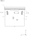
FIG. 3 is a bottom view depicting a part of the electronic device in the fixed state of the display panel. -
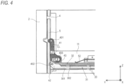
FIG. 4 is a side view depicting a part of the electronic device in the fixed state of the display panel. -
FIG. 5 is a perspective view depicting a part of the electronic device in a state where the display panel has moved forwards. -
FIG. 6 is a bottom view depicting a part of the electronic device in the state where the display panel has moved forwards. -
FIG. 7 is a side view depicting a part of the electronic device in the state where the display panel has moved forwards. -
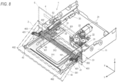
FIG. 8 is a perspective view depicting a part of the electronic device in an inclined state of the display panel. -
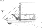
FIG. 9 is a side view depicting a state where a motion link of the electronic device is in contact with a main slider. -
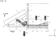
FIG. 10 is a side view depicting a state where the motion link further moves by a predetermined distance after contacting the main slider. - Hereinafter, illustrative embodiments will be described in detail with reference to the accompanying drawings.
-
FIG. 1 depicts an outward appearance of anelectronic device 10 according to an illustrative embodiment. Theelectronic device 10 is a device that is to be mounted on a vehicle such as an automobile and is to be used in a vehicle interior. Theelectronic device 10 has a navigation function of guiding a route to a destination and an audio function of outputting voice into the vehicle interior. - In below description, a three dimensional Cartesian coordinate system (XYZ) shown in the drawings is used to appropriately indicate directions and orientations. The Cartesian coordinate system is relatively fixed to a
main body 1. An X-axis direction corresponds to a left-right direction, a Y-axis direction corresponds to a front-back direction, and a Z-axis direction corresponds to an upper-lower direction. A +X-side is a left side of a display surface of adisplay panel 2, and a -X-side is a right side of the display surface. A +Y-side is a front side of the display surface, and a - Y-side is a backside of the display surface. A +Z-side is an upper side and a -Z-side is a lower side. - The
electronic device 10 has amain body 1, adisplay panel 2 and afront panel 5. - As shown in
FIG. 2 , themain body 1 has achassis 11. In thechassis 11, a plurality of components for implementing a variety of functions of theelectronic device 10 is accommodated. - As shown in
FIG. 1 , thedisplay panel 2 has a display 3 (an example of the display surface) such as a liquid crystal monitor. The display surface of thedisplay panel 2 has a substantially rectangular shape having a longitudinal direction and a width direction. Thedisplay panel 2 functions as the display unit of theelectronic device 10. - The display 3 has a touch panel. The display 3 is configured to receive a user's operation. The user can input a variety of instructions into the
electronic device 10 by touching command buttons displayed on the display 3. As a result, themain body 1 is configured to execute diverse processing, in response to the user's operation performed on thedisplay panel 2. Thedisplay panel 2 may have a physical operation button with which the user inputs an instruction. - The front panel 5 (an example of the fixing surface) is provided at a front part of the
main body 1. As shown inFIG. 2 , thefront panel 5 has adisc insertion opening 4. When thedisplay panel 2 is in a fixed state, thedisc insertion opening 4 is covered by thedisplay panel 2. - In the below, a configuration of the
electronic device 10 is described. First, a configuration is described when thedisplay panel 2 is in the fixed state, with reference toFIGS. 2 to 4 . In these drawings, some members are shown with being projected for convenience of explanation. - As shown in
FIG. 2 , thedisplay panel 2 is provided in front of (the +Y direction) thefront panel 5. When thedisplay panel 2 is in the fixed state, thedisplay panel 2 covers the substantially entire surface (front surface) of thefront panel 5. Thereby, thedisc insertion opening 4 is covered by thedisplay panel 2. - The
electronic device 10 has amotor 21, a plurality ofgears 22 and amain slider 31. Themotor 21, the plurality ofgears 22 and themain slider 31 are provided on a bottom of thechassis 11. Themotor 21 is configured to generate a driving force. The plurality ofgears 22 is configured to transmit the driving force of themotor 21 to themain slider 31. - The main slider 31 (an example of the first movement part) has a pair of left and right (the X-axis direction) sliding
members 301 and acoupling member 311. The pair of slidingmembers 301 extends in the front-back direction (the Y-axis direction) of thechassis 11. Both sides of thechassis 11 are provided with a pair of guide rails 33. Each slidingmember 301 is engaged with thecorresponding guide rail 33 and is kept to freely slide in the front-back direction (the Y-axis direction) of thechassis 11. Thecoupling member 311 extends in the left-right direction (the X-axis direction) of thechassis 11 and is configured to couple front end portions of the pair of slidingmembers 301. Themain slider 31 is configured to slide in the front-back direction (the Y-axis direction), which is a direction intersecting with thefront panel 5, by the driving force generated from themotor 21. - Each sliding
member 301 is formed with apin sliding path 101. Thepin sliding path 101 is a long hole extending in the front-back direction (the Y-axis direction) of thechassis 11. As shown inFIG. 3 , a pair ofguide paths 102 is formed at a front part of a bottom surface of thechassis 11. A front end portion of eachpin sliding path 101 overlaps with a rear end portion of thecorresponding guide path 102, as seen from the Z-axis direction. Theelectronic device 10 has a pair of coupling pins 51. Eachcoupling pin 51 is inserted into the correspondingpin sliding path 101 and thecorresponding guide path 102. - Each
coupling pin 51 has a barrel cylinder having a flange (not shown) inserted into the part at which thepin sliding path 101 and theguide path 102 overlap each other, a friction ring fitted to the barrel cylinder and a screw screwed to the barrel cylinder. - As shown in
FIG. 2 , theelectronic device 10 has a sub-slider 32 (an example of the second movement part). The sub-slider 32 has a pair of slidingmembers 302 and aconnection member 312. The pair of slidingmembers 302 extends in the front-back direction (the Y-axis direction) of thechassis 11. Each slidingmember 302 is engaged with thecorresponding guide rail 33 and is kept to freely slide in the front-back direction (the Y-axis direction) of thechassis 11. Theconnection member 312 extends in the left-right direction (the X-axis direction) of thechassis 11, and is configured to couple front end portions of the pair of slidingmembers 302. Eachcoupling pin 51 is inserted into a predetermined part of the corresponding slidingmember 302 in the upper-lower direction (the Z-axis direction). - A pair of plate springs 52, which are elastic members, is provided in the vicinity of left and right sides (the X-axis direction) of the
chassis 11. As shown inFIG. 4 , eachplate spring 52 is in contact with the corresponding slidingmember 302 of the sub-slider 32. Eachplate spring 52 is configured to press the corresponding slidingmember 302 towards the corresponding slidingmember 301 of themain slider 31. - As shown in
FIG. 2 , thedisplay panel 2 has a pair ofshafts 401 and a pair ofshafts 402. The pair ofshafts 401 is provided at substantially central portions in the upper-lower direction of left and right sides of thedisplay panel 2. The pair ofshafts 402 is provided at lower portions in the upper-lower direction of left and right sides of thedisplay panel 2. The sub-slider 32 has a pair ofshafts 403. Also, the front end portion of each slidingmember 302 of the sub-slider 32 forms anarm part 43. Eachshaft 403 is provided at thecorresponding arm part 43. - The
electronic device 10 has a pair of motion links 41 (an example of the support part). As shown inFIG. 4 , eachmotion link 41 is a member having a first part LP and a second part SP. The first part LP is longer than the second part SP. The first part LP and the second part SP extend in intersecting directions and form a bent part CL. When thedisplay panel 2 is in the fixed state, each of the first parts LP extends in the upper-lower direction and each of the second parts SP extends in the front-back direction. Each of the first parts LP is rotatably connected to the corresponding shaft 401 (which is an example of the second connection part). Each of the second parts SP is rotatably connected to the corresponding shaft 403 (which is an example of the third connection part). Thereby, one end portion of eachmotion link 41 and thedisplay panel 2 are configured to freely rotate relative to each other about thecorresponding shaft 401. The other end portion of eachmotion link 41 is configured to freely rotate relative to the sub-slider 32 about thecorresponding shaft 403. - The front end portion of each sliding
member 301 of themain slider 31 forms anarm part 42. Eacharm part 42 is rotatably connected to the corresponding shaft 402 (which is an example of the first connection part). Thereby, thedisplay panel 2 is configured to be rotatable relative to eacharm part 42 about thecorresponding shaft 402. As described above, each slidingmember 301 is engaged with thecorresponding guide rail 33 provided for thechassis 11, and is kept to freely slide in the front-back direction (the Y-axis direction). As shown inFIG. 4 , eachguide rail 33 has a plurality of convex portions. The plurality of convex portions is arranged at different positions in the front-back direction (the Y-axis direction). The plurality of convex portions is arranged at positions facing the slidingmember 301. The plurality of convex portions is kept to sandwich the slidingmember 301 in the upper-lower direction. Each slidingmember 302 of the sub-slider 32 is provided on thecorresponding guide rail 33. - In the below, change in posture of the
display panel 2 is described. First, a forward (the +Y direction) moving process of thedisplay panel 2 from the fixed state ofFIG. 2 is described with reference toFIGS. 5 to 7 . - When the user operates a command button displayed on the display 3 or a physical operation button, for example, an instruction signal for operating the
display panel 2 is output. Themotor 21 starts an operation in response to the instruction signal, and drives the plurality ofgears 22. The plurality ofgears 22 is driven, so that the slidingmember 301 engaged with one of the plurality ofgears 22 is moved forwards (the +Y direction), as shown inFIGS. 5 and7 . That is, themain slider 31 is moved forwards. - As each sliding
member 301 is moved, eachcoupling pin 51 engaged with the front end portion of eachpin sliding path 101 is moved forwards (the +Y direction) along eachguide path 102 from the rear end portion thereof. Accompanied by this movement, the corresponding slidingmember 302 of the sub-slider 32 also starts to move forwards. That is, as themain slider 31 is moved, the sub-slider 32 is moved in the same direction as themain slider 31. - As each sliding
member 302 of the sub-slider 32 is moved, the correspondingmotion link 41 supported to theshaft 403 provided for eacharm part 43 also starts to move forwards. Also, since thearm part 42 of each slidingmember 301 also starts to move forwards, thedisplay panel 2 is moved forwards. At this time, since eacharm part 42 is moved forwards earlier than themotion link 41, thedisplay panel 2 is moved with an inclined posture where the upper end thereof is located slightly posterior to the lower end thereof. - As each sliding
member 302 is moved, eachcoupling pin 51 reaches the front end portion of thecorresponding guide path 102 and stops, as shown inFIG. 6 . In this state, since eachcoupling pin 51 can continue to move along the correspondingpin sliding path 101, the corresponding slidingmember 301 continues to move forwards. In other words, eachcoupling pin 51 moves towards the rear end along the correspondingpin sliding path 101, so that it moves rearwards relative to the corresponding slidingmember 301. - In the below, an operation that is performed until the
display panel 2 shown inFIGS. 5 and7 reaches the inclined state from a state where the display panel has moved forwards (the +Y direction) by a predetermined distance is described with reference toFIGS. 8 to 10 . - After each
coupling pin 51 reaches the front end portion of thecorresponding guide path 102, thearm part 42 of the slidingmember 301 continues to move forwards (the +Y direction), so that the lower end of thedisplay panel 2 moves forwards, as shown inFIG. 8 . Thereby, thedisplay panel 2 is tilted so that the front surface (the display surface) thereof faces upwards obliquely. Upon the start of the operation, the upper end of thedisplay panel 2 is spaced forwards from the surface (front surface) of thefront panel 5, as shown inFIG. 7 . For this reason, when thedisplay panel 2 transitions to the inclined state, thedisplay panel 2 is not contacted to the surface of thefront panel 5. - When the
display panel 2 is tilted, eachmotion link 41 is contacted to themain slider 31, as shown inFIG. 9 . Specifically, a corner part CP (a part shown with a black square) of eachmotion link 41 is contacted to the corresponding slidingmember 301. The bent part CL of themotion link 41 forms a corner part that is convex towards the corresponding slidingmember 301. The corner part CP corresponds to the corner part. - Since the corner part CP, which is convex towards the corresponding sliding
member 301, is contacted to the drivingmember 301, the corner part CP and the corresponding slidingmember 301 are contacted to each other immediately after thedisplay panel 2 is tilted as the slidingmember 301 is moved. Thereby, when thedisplay panel 2 is tilted, the bending of each slidingmember 301 is immediately suppressed, so that it is possible to suppress an abnormal sound from each member upon the change in posture of thedisplay panel 2 and in the inclined state. In the meantime, at the time that each corner part CP and the corresponding slidingmember 301 are contacted to each other, eachcoupling pin 51 is positioned between the front end portion and the rear end portion of the correspondingpin sliding path 101. - Herein, an operation that is performed until each corner part CP and the corresponding sliding
member 301 are contacted to each other is described in detail. Each slidingmember 301 is moved by a first distance, which is the predetermined distance, towards the front (the +Y direction) shown with an arrow AR1 inFIG. 9 , so that thedisplay panel 2 is rotated in a clockwise direction (as seen from a right side) shown with an arrow AR2 about therespective shafts FIGS. 7 and9 , eachmotion link 41 is rotated in a counterclockwise direction (as seen from a right side) about thecorresponding shaft 403. As a result, the corner part CP of eachmotion link 41 and the corresponding slidingmember 301 are contacted to each other, and a downward (vertical direction) force (bias) shown with an arrow AR3 is applied to the contact part thereof. The first distance by which each slidingmember 301 moves is about 10 cm on the basis of the position of themember 301 in the fixed state of thedisplay panel 2, for example. - Herein, the parts of the plurality of convex portions provided for the
respective guide rails 33, which are contacted to the corresponding slidingmember 301, are denoted as contact parts TP1, TP2 shown with black circles. For example, a contact part between the contact part TP1 and the slidingmember 301 is denoted as a first support point, and a distance from the first support point to theshaft 402 is denoted as a distance L1. On the other hand, a contact part between the contact part TP2 and the slidingmember 301 is denoted as a second support point, and a distance from the second support point to theshaft 402 is denoted as a distance L2. The distance L1 is greater than the distance L2. As a result, regarding the moment generated at theshaft 402, the moment based on the second support point is less than the moment based on the first support point. In this way, the second support point is provided in addition to the first support point, so that it is possible to securely suppress the bending of the slidingmember 301, thereby suppressing the abnormal sound from each member upon the change in posture of thedisplay panel 2 and in the inclined state. As a result, the stability of the posture change operation of thedisplay panel 2 is also improved. - On the other hand, the downward force (bias) shown with the arrow AR3 is applied at the second support point, so that an upward force (bias) shown with an arrow AR4 is applied at the first support point. Also, an upward force (bias) shown with an arrow AR5 is applied to the contact part between the contact part TP2 and the sliding
member 301. In this way, the upward forces are received by the plurality of convex portions provided for therespective guide rails 33, so that it is possible to securely suppress the bending of each slidingmember 301. Also, the corner part CP of eachmotion link 41, which is used when tilting thedisplay panel 2, is brought into contact with the corresponding slidingmember 301. Thereby, as compared to a configuration where a member configured to contact each slidingmember 301 is newly provided on a backside of thedisplay panel 2, for example, it is possible to reduce the number of components, thereby saving the manufacturing cost. - As shown in
FIG. 10 , even after each corner part CP is contacted to the corresponding slidingmember 301, each slidingmember 301 is further moved forwards by the second distance. The second distance is about 5 mm, for example. In this state, eachcoupling pin 51 is engaged with the rear end portion of thepin sliding path 101 formed in the corresponding slidingmember 301. - At this time, a weight of the
display panel 2 and a force with which thedisplay panel 2 is tilted in the rotating direction of the arrowAR2 are composed, so that a downward force denoted by an arrow AR3a is generated at the second support point. That is, the force stronger than the downward force denoted with the arrow AR3 ofFIG. 9 is applied to each slidingmember 301. In addition to this configuration, since eachcoupling pin 51 is engaged to the rear end portion of the correspondingpin sliding path 101, even when the vibrations are transmitted from a vehicle body, each slidingmember 301 is difficult to be displaced and deformed and thedisplay panel 2 is difficult to be shaken. Therefore, it is possible to suppress the abnormal sound from each member upon the change in posture of thedisplay panel 2 and in the inclined state and to secure the stability of the posture change operation of thedisplay panel 2. - In this way, even after each corner part CP and the corresponding sliding
member 301 are contacted to each other, each slidingmember 301 is further moved forwards, so that eachmotion link 41 continues to rotate in the counterclockwise direction (as seen from a right side) and the downward force (bias) denoted with the arrow AR3a increases at the contact part thereof. Thereby, it is possible to further increase the rigidity of each slidingmember 301 against the vibrations to be transmitted from the vehicle body. As a result, the bending of each slidingmember 301 is suppressed, so that it is possible to further suppress the abnormal sound from each member during the change in posture of thedisplay panel 2 and in the inclined state. In the meantime, each slidingmember 301 is moved, so that the respective distances from the first support point and the second support point to theshaft 402 are increased. Specifically, the distance L1 becomes L1a (L1<L1a), and the distance L2 becomes L2a (L2<L2a). - As the downward force increases, the upward force (bias) denoted with an arrow AR4a at the first support point (the contact part TP1) and the upward force (bias) denoted with an arrow AR5a at the second support point (the contact part TP2) increase. However, since the corresponding forces are received by the plurality of convex portions provided for the
respective guide rails 33, it is possible to further suppress the bending of each slidingmember 301. - When each sliding
member 301 is moved and thus eachcoupling pin 51 is relatively retreated and reaches the rear end portion of the correspondingpin sliding path 101, as described above, a sensor (not shown) detects the reaching and stops the operation of themotor 21. Thereby, the driving of the plurality ofgears 22 is also stopped and the movement of each slidingmember 301 is also stopped. At this time, thedisplay panel 2 is in the inclined state, and thedisc insertion opening 4 is exposed to the user. - After the user inserts or acquires a disc through the
disc insertion opening 4, themotor 21 rotates in a reverse direction to the operation of moving thedisplay panel 2 to the inclined state. Thereby, each slidingmember 301 starts to move rearwards (the -Y direction), and thedisplay panel 2 gradually stands up. - Each sliding
member 301 is moved rearwards, so that eachcoupling pin 51 is moved forwards (the +Y direction) from the rear end portion of the correspondingpin sliding path 101. When eachcoupling pin 51 reaches and is engaged to the front end portion of the correspondingpin sliding path 101, eachcoupling pin 51 starts to move along thecorresponding guide path 102. Thereby, thedisplay panel 2 is moved rearwards with the posture where the display surface faces upwards obliquely to some extent. As a result, the upper end portion of thedisplay panel 2 is first contacted to thefront panel 5 earlier than the lower end portion to which the driving force is applied. Thereby, the adhesion of thedisplay panel 2 to themain body 1 is improved. - Although the illustrative embodiment of the present invention has been described, the present invention is not limited to the illustrative embodiment and a variety of modifications can be made. In the below, modified embodiments not falling within the scope of the invention as defined by the appended claims are described. All aspects including the above illustrative embodiment and modified embodiments to be described below can be appropriately combined.
- In the above illustrative embodiment, each
motion link 41 is a single member having the first part LP and the second part SP. However, eachmotion link 41 may also be formed by bonding a plurality of members. For example, eachmotion link 41 may have a configuration where the first part LP and the second part SP provided as separate members are bonded at the bonding part CL. - Also, each
motion link 41 may have another appropriate shape inasmuch as it accomplishes the above operational effects by changing the posture of thedisplay panel 2 and contacting the corresponding slidingmember 301. - In the above illustrative embodiment, the
electronic device 10 is fixed to the vehicle such as an automobile. However, theelectronic device 10 may also be fixed in other places of buildings such as home, a store, an office, a factory and the like. - In the above illustrative embodiment, the control functions of the
electronic device 10 are implemented in the software manner by the calculation processing of the CPU in accordance with the programs. However, some of the control functions may be implemented by an electrical hardware circuit.
Claims (3)
- An electronic device (10) comprising:a main body (1) fixed to a target and having a front panel (5);a display unit (2) having a display surface (3) for displaying information;a main slider (31) having a pair of arm parts (42) and being connected to a lower end of the display unit (2) and configured to linearly reciprocally move relative to the main body (1), wherein the electronic device has a motor (21) and a gear (22) arrangement which enables movement of the main slider (31);a sub-slider (32) configured to move in parallel with the main slider (31);a pair of motion links (41) configured to support the display unit (2);a first pair of shafts (402) which is connected between a lower end portion of the display unit (2) and the main slider (31) in order to enable rotation of the display unit (2) relative to the main slider (31);a second pair of shafts (401) which is connected to the display unit (2) at a position between the lower end portion and an upper end portion of the display unit (2) and to one end portion of the pair of motion links (41) in order to enable rotation of the display unit (2) relative to the pair of motion links (41), anda third pair of shafts (403) which is connected between the other end portion of the pair of motion links (41) and the sub-slider (32) in order to enable rotation of the pair of motion links (41) relative to the sub-slider (32),wherein the display unit (2) can transition between a fixed state and an inclined state in accordance with the movement of the main slider (31),wherein in the fixed state, the upper end portion and the rear end portion of the display unit (2) are fixed to the front panel (5),wherein in the inclined state, the display unit (2) is spaced from the front panel (5) and the display surface (3) faces upwards obliquely, andwherein when the main slider (31) moves forwards by a first distance from a position in the fixed state, the pair of motion links (41) comes into contact with the main slider (31), wherein each motion link (41) has a first part (LP) and a second part (SP), where the first part is longer than the second part and forms a bent part (CL), where the longer part (LP) is connected to the display unit via the corresponding second shaft (401), such that when the display panel is in the fixed state, each of the first parts (LP) extends in the upper-lower direction and each of the second parts (SP) extends in the front-back direction; the bent part (CL) has a corner part (CP) which comes into contact with the main slider (31) when the main slider (31) is moved the first distance; and each of the second parts (SP) is rotatably connected to the corresponding third shaft (403).
- The electronic device (10) according to claim 1, wherein the main slider (31) is configured to further move forwards by a second distance after the main slider (31) has come into contact with the corner part (CP) of the motion link (41) until the display unit (2) reaches the inclined state.
- The electronic device (10) according to claim 2, wherein the main slider (31) has a sliding path (101) which follows a direction of the movement path of the main slider (31),wherein a pair of coupling pins (51) inserted into the sub-slider (32) and the sliding path (101) and configured to slide along the sliding path (101) is provided,wherein the pair of coupling pins (51) is positioned between a front end portion and a rear end portion of the sliding path (101) when the main slider (31) and the motion link (41) first come into contact with each other, andwherein the pair of coupling pins (51) is engaged with the rear end portion of the sliding path (101) when the main slider (31) moves forwards by the second distance.
Applications Claiming Priority (2)
| Application Number | Priority Date | Filing Date | Title |
|---|---|---|---|
| JP2014071864A JP6325312B2 (en) | 2014-03-31 | 2014-03-31 | Electronics |
| PCT/JP2015/054642 WO2015151633A1 (en) | 2014-03-31 | 2015-02-19 | Electronic device |
Publications (3)
| Publication Number | Publication Date |
|---|---|
| EP3128821A1 EP3128821A1 (en) | 2017-02-08 |
| EP3128821A4 EP3128821A4 (en) | 2017-12-27 |
| EP3128821B1 true EP3128821B1 (en) | 2025-01-01 |
Family
ID=54239969
Family Applications (1)
| Application Number | Title | Priority Date | Filing Date |
|---|---|---|---|
| EP15773955.8A Active EP3128821B1 (en) | 2014-03-31 | 2015-02-19 | Electronic device |
Country Status (6)
| Country | Link |
|---|---|
| US (1) | US9903722B2 (en) |
| EP (1) | EP3128821B1 (en) |
| JP (1) | JP6325312B2 (en) |
| CN (1) | CN105917752B (en) |
| ES (1) | ES3005222T3 (en) |
| WO (1) | WO2015151633A1 (en) |
Families Citing this family (1)
| Publication number | Priority date | Publication date | Assignee | Title |
|---|---|---|---|---|
| JP6646617B2 (en) * | 2017-05-22 | 2020-02-14 | 本田技研工業株式会社 | Automatic driving control device |
Family Cites Families (12)
| Publication number | Priority date | Publication date | Assignee | Title |
|---|---|---|---|---|
| JP3820324B2 (en) * | 1998-05-21 | 2006-09-13 | アルパイン株式会社 | Front panel device for in-vehicle equipment |
| JP2003276516A (en) * | 2002-03-25 | 2003-10-02 | Nifco Inc | Guiding mechanism, opening/closing mechanism of lid body using guiding mechanism, and on-vehicle interior part using guiding mechanism |
| JP4171306B2 (en) * | 2003-01-07 | 2008-10-22 | アルパイン株式会社 | Front panel device for in-vehicle electronic equipment |
| US20040261301A1 (en) * | 2003-06-30 | 2004-12-30 | Vering Andrew L. | High rotation linkage assembly |
| KR100522998B1 (en) * | 2003-09-15 | 2005-10-19 | 현대모비스 주식회사 | Monitor Tilting Apparatus of AV System for Motor Vehicle |
| JP4245451B2 (en) | 2003-10-03 | 2009-03-25 | 三菱電機株式会社 | Panel drive device for in-vehicle equipment |
| JP4368253B2 (en) * | 2004-06-11 | 2009-11-18 | アルパイン株式会社 | Electronic device having a movable panel |
| JP4793072B2 (en) * | 2006-04-17 | 2011-10-12 | 株式会社ケンウッド | In-vehicle electronic device guide structure, in-vehicle electronic device, and rattling prevention method |
| JP5012029B2 (en) * | 2007-01-04 | 2012-08-29 | ソニー株式会社 | Car equipment |
| JP2009120075A (en) * | 2007-11-16 | 2009-06-04 | Clarion Co Ltd | Slope mechanism and on-vehicle acoustic device equipped with the same |
| JP2010076574A (en) * | 2008-09-25 | 2010-04-08 | Kenwood Corp | Panel device |
| WO2012093420A1 (en) * | 2011-01-07 | 2012-07-12 | 三菱電機株式会社 | Panel driving device |
-
2014
- 2014-03-31 JP JP2014071864A patent/JP6325312B2/en active Active
-
2015
- 2015-02-19 WO PCT/JP2015/054642 patent/WO2015151633A1/en not_active Ceased
- 2015-02-19 ES ES15773955T patent/ES3005222T3/en active Active
- 2015-02-19 CN CN201580004768.9A patent/CN105917752B/en active Active
- 2015-02-19 EP EP15773955.8A patent/EP3128821B1/en active Active
- 2015-02-19 US US15/100,423 patent/US9903722B2/en active Active
Also Published As
| Publication number | Publication date |
|---|---|
| ES3005222T3 (en) | 2025-03-14 |
| US20160305786A1 (en) | 2016-10-20 |
| US9903722B2 (en) | 2018-02-27 |
| CN105917752B (en) | 2018-10-30 |
| JP2015195255A (en) | 2015-11-05 |
| EP3128821A1 (en) | 2017-02-08 |
| CN105917752A (en) | 2016-08-31 |
| WO2015151633A1 (en) | 2015-10-08 |
| JP6325312B2 (en) | 2018-05-16 |
| EP3128821A4 (en) | 2017-12-27 |
Similar Documents
| Publication | Publication Date | Title |
|---|---|---|
| US10061396B1 (en) | Electronic apparatus | |
| CN106354202B (en) | Input device and electronic apparatus | |
| US20110074559A1 (en) | Mounting Apparatus For A Haptic Surface | |
| TWI539884B (en) | Electronic device | |
| JP2013182424A (en) | Input device | |
| US20130201621A1 (en) | Electronic apparatus having a display panel | |
| US10338680B2 (en) | Operating apparatus having feedback mechanism | |
| JP7098412B2 (en) | In-vehicle display device equipped with a response force generator and a response force generator | |
| US9811162B2 (en) | Operating device | |
| US9903722B2 (en) | Electronic device | |
| CN111164550A (en) | Touch panel display device | |
| JP2013182425A (en) | Input device | |
| US20190120625A1 (en) | Mems device | |
| US10509502B2 (en) | Operating device | |
| EP4057112A1 (en) | Cursor positioning device | |
| JP6383306B2 (en) | Press operation device | |
| US10197403B2 (en) | Electronic device | |
| CN113168986B (en) | Interactive change-over switch and electronic equipment | |
| CN109298788B (en) | Haptic feedback devices | |
| EP3410274B1 (en) | Tactile sensation providing device | |
| JP6524870B2 (en) | Electronics | |
| JP7088101B2 (en) | Seesaw switch and electronic equipment | |
| JP5762242B2 (en) | Monitor panel device | |
| JP2022176296A (en) | seesaw switch and electronic equipment |
Legal Events
| Date | Code | Title | Description |
|---|---|---|---|
| STAA | Information on the status of an ep patent application or granted ep patent |
Free format text: STATUS: THE INTERNATIONAL PUBLICATION HAS BEEN MADE |
|
| PUAI | Public reference made under article 153(3) epc to a published international application that has entered the european phase |
Free format text: ORIGINAL CODE: 0009012 |
|
| STAA | Information on the status of an ep patent application or granted ep patent |
Free format text: STATUS: REQUEST FOR EXAMINATION WAS MADE |
|
| 17P | Request for examination filed |
Effective date: 20160613 |
|
| AK | Designated contracting states |
Kind code of ref document: A1 Designated state(s): AL AT BE BG CH CY CZ DE DK EE ES FI FR GB GR HR HU IE IS IT LI LT LU LV MC MK MT NL NO PL PT RO RS SE SI SK SM TR |
|
| AX | Request for extension of the european patent |
Extension state: BA ME |
|
| RIN1 | Information on inventor provided before grant (corrected) |
Inventor name: ARAI HIDEO Inventor name: SANO TETSUO Inventor name: JO TAKAHIRO |
|
| DAX | Request for extension of the european patent (deleted) | ||
| A4 | Supplementary search report drawn up and despatched |
Effective date: 20171127 |
|
| RIC1 | Information provided on ipc code assigned before grant |
Ipc: G01C 21/16 20060101AFI20171121BHEP Ipc: H05K 5/02 20060101ALI20171121BHEP Ipc: G09F 9/00 20060101ALI20171121BHEP Ipc: B60K 35/00 20060101ALI20171121BHEP |
|
| STAA | Information on the status of an ep patent application or granted ep patent |
Free format text: STATUS: EXAMINATION IS IN PROGRESS |
|
| 17Q | First examination report despatched |
Effective date: 20210208 |
|
| REG | Reference to a national code |
Ref country code: DE Ref legal event code: R079 Free format text: PREVIOUS MAIN CLASS: H05K0005020000 Ipc: G01C0021160000 Ref country code: DE Ref legal event code: R079 Ref document number: 602015090758 Country of ref document: DE Free format text: PREVIOUS MAIN CLASS: H05K0005020000 Ipc: G01C0021160000 |
|
| RIC1 | Information provided on ipc code assigned before grant |
Ipc: B60K 35/53 20240101ALI20240620BHEP Ipc: B60K 35/50 20240101ALI20240620BHEP Ipc: B60K 35/22 20240101ALI20240620BHEP Ipc: G01C 21/26 20060101ALI20240620BHEP Ipc: G09F 9/00 20060101ALI20240620BHEP Ipc: H05K 5/02 20060101ALI20240620BHEP Ipc: B60K 35/00 20060101ALI20240620BHEP Ipc: G01C 21/16 20060101AFI20240620BHEP |
|
| GRAP | Despatch of communication of intention to grant a patent |
Free format text: ORIGINAL CODE: EPIDOSNIGR1 |
|
| STAA | Information on the status of an ep patent application or granted ep patent |
Free format text: STATUS: GRANT OF PATENT IS INTENDED |
|
| INTG | Intention to grant announced |
Effective date: 20240920 |
|
| GRAS | Grant fee paid |
Free format text: ORIGINAL CODE: EPIDOSNIGR3 |
|
| GRAA | (expected) grant |
Free format text: ORIGINAL CODE: 0009210 |
|
| STAA | Information on the status of an ep patent application or granted ep patent |
Free format text: STATUS: THE PATENT HAS BEEN GRANTED |
|
| AK | Designated contracting states |
Kind code of ref document: B1 Designated state(s): AL AT BE BG CH CY CZ DE DK EE ES FI FR GB GR HR HU IE IS IT LI LT LU LV MC MK MT NL NO PL PT RO RS SE SI SK SM TR |
|
| REG | Reference to a national code |
Ref country code: GB Ref legal event code: FG4D |
|
| REG | Reference to a national code |
Ref country code: CH Ref legal event code: EP |
|
| REG | Reference to a national code |
Ref country code: DE Ref legal event code: R096 Ref document number: 602015090758 Country of ref document: DE |
|
| REG | Reference to a national code |
Ref country code: IE Ref legal event code: FG4D |
|
| REG | Reference to a national code |
Ref country code: ES Ref legal event code: FG2A Ref document number: 3005222 Country of ref document: ES Kind code of ref document: T3 Effective date: 20250314 |
|
| PGFP | Annual fee paid to national office [announced via postgrant information from national office to epo] |
Ref country code: DE Payment date: 20250218 Year of fee payment: 11 |
|
| PGFP | Annual fee paid to national office [announced via postgrant information from national office to epo] |
Ref country code: ES Payment date: 20250303 Year of fee payment: 11 |
|
| PGFP | Annual fee paid to national office [announced via postgrant information from national office to epo] |
Ref country code: FR Payment date: 20250224 Year of fee payment: 11 |
|
| REG | Reference to a national code |
Ref country code: LT Ref legal event code: MG9D |
|
| REG | Reference to a national code |
Ref country code: NL Ref legal event code: MP Effective date: 20250101 |
|
| REG | Reference to a national code |
Ref country code: AT Ref legal event code: MK05 Ref document number: 1756646 Country of ref document: AT Kind code of ref document: T Effective date: 20250101 |
|
| PG25 | Lapsed in a contracting state [announced via postgrant information from national office to epo] |
Ref country code: NL Free format text: LAPSE BECAUSE OF FAILURE TO SUBMIT A TRANSLATION OF THE DESCRIPTION OR TO PAY THE FEE WITHIN THE PRESCRIBED TIME-LIMIT Effective date: 20250101 |
|
| PG25 | Lapsed in a contracting state [announced via postgrant information from national office to epo] |
Ref country code: FI Free format text: LAPSE BECAUSE OF FAILURE TO SUBMIT A TRANSLATION OF THE DESCRIPTION OR TO PAY THE FEE WITHIN THE PRESCRIBED TIME-LIMIT Effective date: 20250101 |
|
| PG25 | Lapsed in a contracting state [announced via postgrant information from national office to epo] |
Ref country code: PL Free format text: LAPSE BECAUSE OF FAILURE TO SUBMIT A TRANSLATION OF THE DESCRIPTION OR TO PAY THE FEE WITHIN THE PRESCRIBED TIME-LIMIT Effective date: 20250101 |
|
| PG25 | Lapsed in a contracting state [announced via postgrant information from national office to epo] |
Ref country code: IS Free format text: LAPSE BECAUSE OF FAILURE TO SUBMIT A TRANSLATION OF THE DESCRIPTION OR TO PAY THE FEE WITHIN THE PRESCRIBED TIME-LIMIT Effective date: 20250501 Ref country code: NO Free format text: LAPSE BECAUSE OF FAILURE TO SUBMIT A TRANSLATION OF THE DESCRIPTION OR TO PAY THE FEE WITHIN THE PRESCRIBED TIME-LIMIT Effective date: 20250401 |
|
| PG25 | Lapsed in a contracting state [announced via postgrant information from national office to epo] |
Ref country code: HR Free format text: LAPSE BECAUSE OF FAILURE TO SUBMIT A TRANSLATION OF THE DESCRIPTION OR TO PAY THE FEE WITHIN THE PRESCRIBED TIME-LIMIT Effective date: 20250101 |
|
| PG25 | Lapsed in a contracting state [announced via postgrant information from national office to epo] |
Ref country code: PT Free format text: LAPSE BECAUSE OF FAILURE TO SUBMIT A TRANSLATION OF THE DESCRIPTION OR TO PAY THE FEE WITHIN THE PRESCRIBED TIME-LIMIT Effective date: 20250502 Ref country code: LV Free format text: LAPSE BECAUSE OF FAILURE TO SUBMIT A TRANSLATION OF THE DESCRIPTION OR TO PAY THE FEE WITHIN THE PRESCRIBED TIME-LIMIT Effective date: 20250101 |
|
| PG25 | Lapsed in a contracting state [announced via postgrant information from national office to epo] |
Ref country code: GR Free format text: LAPSE BECAUSE OF FAILURE TO SUBMIT A TRANSLATION OF THE DESCRIPTION OR TO PAY THE FEE WITHIN THE PRESCRIBED TIME-LIMIT Effective date: 20250402 Ref country code: BG Free format text: LAPSE BECAUSE OF FAILURE TO SUBMIT A TRANSLATION OF THE DESCRIPTION OR TO PAY THE FEE WITHIN THE PRESCRIBED TIME-LIMIT Effective date: 20250101 |
|
| PG25 | Lapsed in a contracting state [announced via postgrant information from national office to epo] |
Ref country code: AT Free format text: LAPSE BECAUSE OF FAILURE TO SUBMIT A TRANSLATION OF THE DESCRIPTION OR TO PAY THE FEE WITHIN THE PRESCRIBED TIME-LIMIT Effective date: 20250101 |
|
| PG25 | Lapsed in a contracting state [announced via postgrant information from national office to epo] |
Ref country code: CZ Free format text: LAPSE BECAUSE OF FAILURE TO SUBMIT A TRANSLATION OF THE DESCRIPTION OR TO PAY THE FEE WITHIN THE PRESCRIBED TIME-LIMIT Effective date: 20250101 |
|
| PG25 | Lapsed in a contracting state [announced via postgrant information from national office to epo] |
Ref country code: SE Free format text: LAPSE BECAUSE OF FAILURE TO SUBMIT A TRANSLATION OF THE DESCRIPTION OR TO PAY THE FEE WITHIN THE PRESCRIBED TIME-LIMIT Effective date: 20250101 |
|
| REG | Reference to a national code |
Ref country code: CH Ref legal event code: PL |
|
| REG | Reference to a national code |
Ref country code: DE Ref legal event code: R097 Ref document number: 602015090758 Country of ref document: DE |
|
| PG25 | Lapsed in a contracting state [announced via postgrant information from national office to epo] |
Ref country code: SM Free format text: LAPSE BECAUSE OF FAILURE TO SUBMIT A TRANSLATION OF THE DESCRIPTION OR TO PAY THE FEE WITHIN THE PRESCRIBED TIME-LIMIT Effective date: 20250101 |
|
| PG25 | Lapsed in a contracting state [announced via postgrant information from national office to epo] |
Ref country code: DK Free format text: LAPSE BECAUSE OF FAILURE TO SUBMIT A TRANSLATION OF THE DESCRIPTION OR TO PAY THE FEE WITHIN THE PRESCRIBED TIME-LIMIT Effective date: 20250101 |
|
| PG25 | Lapsed in a contracting state [announced via postgrant information from national office to epo] |
Ref country code: MC Free format text: LAPSE BECAUSE OF FAILURE TO SUBMIT A TRANSLATION OF THE DESCRIPTION OR TO PAY THE FEE WITHIN THE PRESCRIBED TIME-LIMIT Effective date: 20250101 |
|
| PG25 | Lapsed in a contracting state [announced via postgrant information from national office to epo] |
Ref country code: LU Free format text: LAPSE BECAUSE OF NON-PAYMENT OF DUE FEES Effective date: 20250219 Ref country code: IT Free format text: LAPSE BECAUSE OF FAILURE TO SUBMIT A TRANSLATION OF THE DESCRIPTION OR TO PAY THE FEE WITHIN THE PRESCRIBED TIME-LIMIT Effective date: 20250101 |
|
| PG25 | Lapsed in a contracting state [announced via postgrant information from national office to epo] |
Ref country code: CH Free format text: LAPSE BECAUSE OF NON-PAYMENT OF DUE FEES Effective date: 20250228 |
|
| PG25 | Lapsed in a contracting state [announced via postgrant information from national office to epo] |
Ref country code: EE Free format text: LAPSE BECAUSE OF FAILURE TO SUBMIT A TRANSLATION OF THE DESCRIPTION OR TO PAY THE FEE WITHIN THE PRESCRIBED TIME-LIMIT Effective date: 20250101 |
|
| PG25 | Lapsed in a contracting state [announced via postgrant information from national office to epo] |
Ref country code: RO Free format text: LAPSE BECAUSE OF FAILURE TO SUBMIT A TRANSLATION OF THE DESCRIPTION OR TO PAY THE FEE WITHIN THE PRESCRIBED TIME-LIMIT Effective date: 20250101 |
|
| PG25 | Lapsed in a contracting state [announced via postgrant information from national office to epo] |
Ref country code: SK Free format text: LAPSE BECAUSE OF FAILURE TO SUBMIT A TRANSLATION OF THE DESCRIPTION OR TO PAY THE FEE WITHIN THE PRESCRIBED TIME-LIMIT Effective date: 20250101 |
|
| PLBE | No opposition filed within time limit |
Free format text: ORIGINAL CODE: 0009261 |
|
| STAA | Information on the status of an ep patent application or granted ep patent |
Free format text: STATUS: NO OPPOSITION FILED WITHIN TIME LIMIT |
|
| REG | Reference to a national code |
Ref country code: BE Ref legal event code: MM Effective date: 20250228 |
|
| 26N | No opposition filed |
Effective date: 20251002 |
|
| GBPC | Gb: european patent ceased through non-payment of renewal fee |
Effective date: 20250401 |
|
| PG25 | Lapsed in a contracting state [announced via postgrant information from national office to epo] |
Ref country code: GB Free format text: LAPSE BECAUSE OF NON-PAYMENT OF DUE FEES Effective date: 20250401 |
|
| PG25 | Lapsed in a contracting state [announced via postgrant information from national office to epo] |
Ref country code: BE Free format text: LAPSE BECAUSE OF NON-PAYMENT OF DUE FEES Effective date: 20250228 |
|
| PG25 | Lapsed in a contracting state [announced via postgrant information from national office to epo] |
Ref country code: IE Free format text: LAPSE BECAUSE OF NON-PAYMENT OF DUE FEES Effective date: 20250219 |