WO2015151633A1 - Electronic device - Google Patents
Electronic device Download PDFInfo
- Publication number
- WO2015151633A1 WO2015151633A1 PCT/JP2015/054642 JP2015054642W WO2015151633A1 WO 2015151633 A1 WO2015151633 A1 WO 2015151633A1 JP 2015054642 W JP2015054642 W JP 2015054642W WO 2015151633 A1 WO2015151633 A1 WO 2015151633A1
- Authority
- WO
- WIPO (PCT)
- Prior art keywords
- moving
- display
- end portion
- display panel
- fixed
- Prior art date
Links
- 230000007704 transition Effects 0.000 abstract description 6
- 230000002159 abnormal effect Effects 0.000 description 11
- 239000013256 coordination polymer Substances 0.000 description 11
- 238000003780 insertion Methods 0.000 description 9
- 230000037431 insertion Effects 0.000 description 9
- 238000005452 bending Methods 0.000 description 7
- 238000006073 displacement reaction Methods 0.000 description 2
- 238000000034 method Methods 0.000 description 2
- 230000004048 modification Effects 0.000 description 2
- 238000012986 modification Methods 0.000 description 2
- 230000008569 process Effects 0.000 description 2
- 206010034719 Personality change Diseases 0.000 description 1
- 230000008859 change Effects 0.000 description 1
- 238000010586 diagram Methods 0.000 description 1
- 230000000694 effects Effects 0.000 description 1
- 239000004973 liquid crystal related substance Substances 0.000 description 1
- 238000004519 manufacturing process Methods 0.000 description 1
- 230000007246 mechanism Effects 0.000 description 1
- 230000004044 response Effects 0.000 description 1
- 230000009466 transformation Effects 0.000 description 1
Images


Classifications
-
- G—PHYSICS
- G01—MEASURING; TESTING
- G01C—MEASURING DISTANCES, LEVELS OR BEARINGS; SURVEYING; NAVIGATION; GYROSCOPIC INSTRUMENTS; PHOTOGRAMMETRY OR VIDEOGRAMMETRY
- G01C21/00—Navigation; Navigational instruments not provided for in groups G01C1/00 - G01C19/00
- G01C21/26—Navigation; Navigational instruments not provided for in groups G01C1/00 - G01C19/00 specially adapted for navigation in a road network
- G01C21/265—Navigation; Navigational instruments not provided for in groups G01C1/00 - G01C19/00 specially adapted for navigation in a road network constructional aspects of navigation devices, e.g. housings, mountings, displays
-
- B—PERFORMING OPERATIONS; TRANSPORTING
- B60—VEHICLES IN GENERAL
- B60K—ARRANGEMENT OR MOUNTING OF PROPULSION UNITS OR OF TRANSMISSIONS IN VEHICLES; ARRANGEMENT OR MOUNTING OF PLURAL DIVERSE PRIME-MOVERS IN VEHICLES; AUXILIARY DRIVES FOR VEHICLES; INSTRUMENTATION OR DASHBOARDS FOR VEHICLES; ARRANGEMENTS IN CONNECTION WITH COOLING, AIR INTAKE, GAS EXHAUST OR FUEL SUPPLY OF PROPULSION UNITS IN VEHICLES
- B60K35/00—Arrangement of adaptations of instruments
-
- B60K35/22—
-
- B60K35/223—
-
- B60K35/50—
-
- B60K35/53—
-
- B60K2360/1442—
-
- B60K2360/145—
-
- B60K35/10—
Definitions
- the present invention relates to an electronic device including a main body having a fixed surface and a display unit capable of taking a posture inclined with respect to the fixed surface.
- the navigation device includes a main body having a fixed surface on which a media insertion slot is formed, and a display having a display surface for displaying information.
- the display unit can take a fixed state in which the display unit is fixed to the fixed surface and an inclined state in which the display unit is inclined with respect to the fixed surface.
- the media insertion slot is exposed, and media can be inserted and ejected.
- the display unit is in a fixed state, the media insertion slot is covered with the display unit.
- the display unit takes a posture parallel to the fixed surface. The operation in which the display unit transitions from the fixed state to the tilted state is called a tilt operation.
- Patent Document 1 discloses an electronic device including a mechanism that enables the tilt operation as described above.
- the display unit in the display device described in Patent Document 1 is supported by a plurality of arms.
- the display unit is rotatable about the support point of each arm.
- the electronic device described in Patent Literature 1 includes a moving unit and a motor.
- the moving part is movable in the front-rear direction with respect to the main body part by the operation of the motor.
- a front end portion of the moving unit is fixed to one of the plurality of arms.
- the display unit is configured to transition to an inclined state.
- an object of the present invention is to suppress the generation of abnormal noise when the posture of the display unit of the electronic device is changed and in an inclined state.
- one aspect of the present invention is an electronic device, A main body fixed to a fixed object and having a fixing surface; A display unit having a display surface for displaying information; A first moving unit connected to a lower end of the display unit and linearly reciprocating with respect to the main body unit; A second moving part capable of reciprocating in parallel with the first moving part; A support part supporting the display part; A first connecting portion connected so that a lower end portion of the display portion is rotatable with respect to the first moving portion; A second connecting portion provided between a lower end portion and an upper end portion of the display portion, and connected so that the display portion and one end portion of the support portion are relatively rotatable; A third connecting portion connected so that the other end of the support portion can rotate with respect to the second moving portion; With The display unit is capable of transitioning between a fixed state and an inclined state with the reciprocating movement of the first moving unit, In the fixed state, the upper end portion and the rear end portion of the display unit are fixed to the fixed surface, In the inclined state, the
- the electronic device described above can be configured as follows.
- the first moving unit is further movable forward by a second distance from when the first moving unit comes into contact with the support unit until the display unit reaches the inclined state.
- the rigidity of the first moving unit with respect to vibration transmitted from the fixed object is further increased. Therefore, the bending of the first moving unit is further suppressed, and the generation of abnormal noise from each member when the posture of the display unit is changed and in the inclined state can be further suppressed.
- the electronic device described above can be configured as follows.
- the support portion has a bent shape so as to form a corner portion that is convex toward the first moving portion, The corner is in contact with the first moving part.
- the deflection of the first moving unit is suppressed as soon as the display unit starts transition to the tilted state. Therefore, when the posture of the display unit is changed and from each member in the tilted state Generation of abnormal noise can be further suppressed.
- the electronic device described above can be configured as follows.
- the first moving part has a sliding path extending in the reciprocating direction,
- a connecting pin is provided which is inserted through the second moving part and the sliding path and is slidable along the sliding path.
- the connecting pin is located between a front end portion and a rear end portion of the sliding path when the first moving portion and the support portion first contact each other, The connecting pin engages with the rear end portion of the sliding path when the first moving portion moves forward by the second distance.
- FIG. 1 is a diagram illustrating an appearance of an electronic apparatus according to an embodiment.
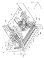
- FIG. 2 is a perspective view showing a part of the electronic device in a fixed state of the display panel.
- FIG. 3 is a bottom view showing a part of the electronic apparatus in a fixed state of the display panel.
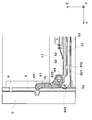
- FIG. 4 is a side view showing a part of the electronic apparatus in a fixed state of the display panel.
- FIG. 5 is a perspective view showing a part of the electronic apparatus in a state where the display panel is moved forward.
- FIG. 6 is a bottom view showing a part of the electronic apparatus in a state where the display panel has moved forward.
- FIG. 7 is a side view showing a part of the electronic apparatus in a state where the display panel is moved forward.
- FIG. 1 is a diagram illustrating an appearance of an electronic apparatus according to an embodiment.
- FIG. 2 is a perspective view showing a part of the electronic device in a fixed state of the display panel.
- FIG. 3 is a bottom view
- FIG. 8 is a perspective view illustrating a part of the electronic device in a tilted state of the display panel.
- FIG. 9 is a side view showing a state in which the motion link in the electronic device is in contact with the main slider.
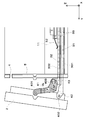
- FIG. 10 is a side view showing a state where the motion link has further moved by a predetermined distance after contacting the main slider.
- FIG. 1 shows an appearance of an electronic device 10 according to an embodiment.
- the electronic device 10 is a device that is mounted on a vehicle such as an automobile and used in a vehicle interior of the vehicle.
- the electronic device 10 has a navigation function for guiding a route to a destination, an audio function for outputting sound into the passenger compartment, and the like.
- XYZ three-dimensional orthogonal coordinate system
- This orthogonal coordinate system is fixed relative to the main body 1.
- the X-axis direction corresponds to the left-right direction
- the Y-axis direction corresponds to the front-back direction
- the Z-axis direction corresponds to the up-down direction.
- the + X side is the left side of the display surface of the display panel 2
- the -X side is the right side of the display surface.
- the + Y side is the front side of the display surface
- the -Y side is the back side of the display surface
- the + Z side is the upper side
- the -Z side is the lower side.
- the electronic device 10 includes a main body 1, a display panel 2, and a front panel 5.
- the main body 1 includes a chassis 11. A plurality of parts for realizing various functions of the electronic device 10 are accommodated in the chassis 11.
- the display panel 2 includes a display 3 (an example of a display surface) such as a liquid crystal display.
- the shape of the display surface of the display panel 2 is a substantially rectangular shape having a longitudinal direction and a short direction.
- the display panel 2 functions as a display unit of the electronic device 10.
- Display 3 has a touch panel.
- the display 3 accepts user operations.
- the user can input various instructions to the electronic device 10 by touching a command button or the like displayed on the display 3.
- the main body 1 executes various processes according to user operations performed on the display panel 2.
- the display panel 2 may include a physical operation button for the user to input an instruction.
- the front panel 5 (an example of a fixed surface) is provided at the front of the main body 1. As shown in FIG. 2, the front panel 5 is provided with a disc insertion slot 4. When the display panel 2 is in a fixed state, the disc insertion slot 4 is covered with the display panel 2.
- a display panel 2 is provided in front of the front panel 5 (+ Y direction).
- the display panel 2 covers substantially the entire surface (front surface) of the front panel 5.
- the disc insertion slot 4 is covered with the display panel 2.
- the electronic device 10 includes a motor 21, a plurality of gears 22, and a main slider 31.
- the motor 21, the plurality of gears 22, and the main slider 31 are provided at the bottom of the chassis 11.
- the motor 21 generates a driving force.
- the plurality of gears 22 transmit the driving force of the motor 21 to the main slider 31.
- the main slider 31 (an example of the first moving unit) includes a pair of left and right (X-axis direction) sliding members 301 and a connecting member 311.
- the pair of sliding members 301 extends in the front-rear direction (Y-axis direction) of the chassis 11.
- a pair of guide rails 33 are provided on both side surfaces of the chassis 11.
- Each sliding member 301 engages with a corresponding guide rail 33 and is slidably held in the front-rear direction (Y-axis direction) of the chassis 11.
- the connecting member 311 extends in the left-right direction (X-axis direction) of the chassis 11 and connects the front end portions of the pair of sliding members 301.
- the main slider 31 is slidable in the front-rear direction (Y-axis direction), which is a direction intersecting the front panel 5, by the driving force generated by the motor 21.
- a pin sliding path 101 is formed in each sliding member 301.
- the pin sliding path 101 is a long hole extending in the front-rear direction (Y-axis direction) of the chassis 11.
- a pair of guide paths 102 are formed at the front portion of the bottom surface of the chassis 11.
- the front end portion of each pin sliding path 101 overlaps the rear end portion of the corresponding guide path 102 when viewed from the Z-axis direction.
- the electronic device 10 includes a pair of connecting pins 51. Each connecting pin 51 is inserted through a corresponding guide slide 102 and a corresponding guide slide 102.
- Each connecting pin 51 includes, for example, a shaft cylinder with a flange (not shown) inserted through a portion where the pin slide path 101 and the guide path 102 overlap, a friction ring fitted to the shaft cylinder, and the shaft And a screw screwed into the cylinder.
- the electronic device 10 includes a sub-slider 32 (an example of a second moving unit).
- the sub-slider 32 includes a pair of sliding members 302 and a connection member 312.
- the pair of sliding members 302 extends in the front-rear direction (Y-axis direction) of the chassis 11.
- Each sliding member 302 engages with the corresponding guide rail 33 and is slidably held in the front-rear direction (Y-axis direction) of the chassis 11.
- the connection member 312 extends in the left-right direction (X-axis direction) of the chassis 11 and connects the front end portions of the pair of sliding members 302.
- Each of the above-described connecting pins 51 is inserted through a predetermined portion of the corresponding sliding member 302 in the vertical direction (Z-axis direction).
- a pair of leaf springs 52 that are elastic bodies are provided in the vicinity of the left and right side surfaces (X-axis direction) of the chassis 11. As shown in FIG. 4, each leaf spring 52 is in contact with the corresponding sliding member 302 of the sub-slider 32. Each leaf spring 52 presses the corresponding sliding member 302 toward the corresponding sliding member 301 of the main slider 31.
- the display panel 2 includes a pair of shafts 401 and a pair of shafts 402.
- the pair of shafts 401 is provided at substantially the center in the vertical direction on the left and right side surfaces of the display panel 2, respectively.
- the pair of shafts 402 are provided at the lower portions in the vertical direction on the left and right side surfaces of the display panel 2, respectively.
- the sub-slider 32 includes a pair of shafts 403. The front end portion of each sliding member 302 in the sub-slider 32 forms an arm portion 43.
- Each shaft 403 is provided on a corresponding arm portion 43.
- the electronic device 10 includes a pair of motion links 41 (an example of a support portion).
- each motion link 41 is a member having a first portion LP and a second portion SP.
- the first part LP is longer than the second part SP.
- the first portion LP and the second portion SP extend in the intersecting direction and form a bent portion CL.
- each first portion LP extends in the up-down direction
- each second portion SP extends in the front-rear direction.
- Each first portion LP is connected to a corresponding shaft 401 so as to be rotatable (an example of a second connection portion).
- Each second portion SP is connected to a corresponding shaft 403 so as to be rotatable (an example of a third connection portion).
- each sliding member 301 in the main slider 31 forms an arm portion 42.
- Each arm portion 42 is connected to a corresponding shaft 402 so as to be rotatable (an example of a first connection portion). Thereby, the display panel 2 can be rotated with respect to each arm portion 42 about the corresponding shaft 402.
- each sliding member 301 engages with a corresponding guide rail 33 provided on the chassis 11 and is slidably held in the front-rear direction (Y-axis direction).
- each guide rail 33 has a plurality of convex portions.
- the plurality of convex portions are arranged at different positions in the front-rear direction (Y-axis direction).
- the plurality of convex portions are arranged at positions facing the sliding member 301.
- the plurality of convex portions hold the sliding member 301 so as to be sandwiched from above and below.
- Each sliding member 302 in the sub-slider 32 is provided on the corresponding guide rail 33.
- an instruction signal for operating the display panel 2 is output.
- the motor 21 starts to operate in response to this instruction signal and drives the plurality of gears 22.
- the sliding member 301 that engages with one of the plurality of gears 22 moves forward (+ Y direction). That is, the main slider 31 moves forward.
- each connecting pin 51 engaged with the front end portion of each pin sliding path 101 moves forward (+ Y direction) from the rear end portion along each guide path 102.
- the sliding member 302 of the corresponding sub-slider 32 also starts moving forward. That is, as the main slider 31 moves, the sub-slider 32 moves in the same direction as the main slider 31.
- each sliding member 302 of the sub-slider 32 along with the movement of each sliding member 302 of the sub-slider 32, the corresponding motion link 41 supported by the shaft 403 provided in each arm portion 43 also starts moving forward. Moreover, since the arm part 42 of each sliding member 301 also starts to move forward at the same time, the display panel 2 moves forward. At this time, since each arm part 42 moves forward ahead of the motion link 41, the display panel 2 moves in an inclined posture in which the upper end side is located slightly behind the lower end side.
- connection pins 51 reach the front end portions of the corresponding guide paths 102 and stop as shown in FIG. In this state, each connecting pin 51 can continue to move in the corresponding pin sliding path 101, so that the corresponding sliding member 301 continues to move forward. In other words, each connecting pin 51 moves rearward relative to the corresponding sliding member 301 by moving the corresponding pin sliding path 101 toward the rear end.
- the arm portion 42 of the sliding member 301 continues to move forward (+ Y direction), as shown in FIG.
- the lower end side of the panel 2 moves forward.
- the display panel 2 tilts so that the front surface (display surface) faces obliquely upward.
- the upper end side of the display panel 2 is spaced forward from the front surface (front surface) of the front panel 5. Therefore, the display panel 2 does not contact the surface of the front panel 5 with the transition to the inclined state.
- each motion link 41 comes into contact with the main slider 31 as shown in FIG. Specifically, the corner portion CP (the portion indicated by a black square) of each motion link 41 comes into contact with the corresponding sliding member 301.
- the bent portion CL of the motion link 41 forms a corner that is convex on the corresponding sliding member 301 side.
- the corner CP corresponds to the corner.
- each connecting pin 51 is located between the front end portion and the rear end portion of the corresponding pin sliding path 101.
- each sliding member 301 moves forward (+ Y direction) indicated by an arrow AR1 in FIG. 9 by a first distance, which is a predetermined distance, so that the display panel 2 uses the respective axes 401 and 402 as rotation axes. It rotates clockwise (viewed from the right) indicated by AR2.
- each motion link 41 rotates counterclockwise (viewed from the right) about the corresponding axis 403.
- each motion link 41 and the corresponding sliding member 301 come into contact with each other, and a downward force (bias downward) indicated by an arrow AR3 is generated at the contact portion between the two.
- the first distance that each sliding member 301 moves is, for example, about 10 cm on the basis of the position of the member 301 when the display panel 2 is fixed.
- contact portions TP1 and TP2 indicated by black circles.
- a contact portion between the contact portion TP1 and the sliding member 301 is a first fulcrum, and a distance from the first fulcrum to the shaft 402 is a distance L1.
- the contact portion between the corner CP and the sliding member 301 is the second fulcrum, and the distance from the second fulcrum to the shaft 402 is the distance L2.
- the distance L1 is longer than the distance L2.
- the moment based on the second fulcrum is smaller than the moment based on the first fulcrum.
- the bending of the sliding member 301 is reliably suppressed, and abnormal noise is generated from each member when the posture of the display panel 2 is changed and in the inclined state. Can be suppressed.
- the stability of the posture changing operation of the display panel 2 is also improved.
- each motion link 41 used when the display panel 2 is tilted into contact with the corresponding sliding member 301 a member that comes into contact with each sliding member 301 is newly added to the back surface of the display panel 2 or the like.
- the number of parts can be reduced and the manufacturing cost can be reduced as compared with the configuration provided in FIG.
- each sliding member 301 further moves forward by the second distance.
- the second distance is about 5 mm.
- each connecting pin 51 engages with the rear end portion of the pin sliding path 101 formed in the corresponding sliding member 301.
- each connecting pin 51 is engaged with the rear end portion of the corresponding pin sliding path 101. Therefore, even if vibration from the vehicle body is transmitted, the displacement or deformation of each sliding member 301 is detected. In addition, the display panel 2 is less likely to shake. Therefore, it is possible to suppress the generation of abnormal noise from each member when the posture of the display panel 2 is changed and in an inclined state, and it is possible to ensure the stability of the posture changing operation of the display panel 2.
- each sliding member 301 moves further forward, so that each motion link 41 is counterclockwise (viewed from the right side).
- the downward force (bias) indicated by the arrow AR3a increases at the contact portion between the two.
- the rigidity of each sliding member 301 with respect to the vibration transmitted from the vehicle body can be further increased.
- the bending of each sliding member 301 is suppressed, and the generation of abnormal noise from each member during the posture change of the display panel 2 and in the inclined state can be further suppressed.
- shaft 402 is extended by the movement of each sliding member 301.
- the distance L1 is L1a (L1 ⁇ L1a)
- the distance L2 is L2a (L2 ⁇ L2a).
- each sliding member 301 starts moving backward ( ⁇ Y direction), and the display panel 2 gradually stands up.
- each connecting pin 51 moves forward (+ Y direction) from the rear end portion of the corresponding pin sliding path 101.
- each connecting pin 51 starts moving along the corresponding guide path 102.
- the display panel 2 moves rearward with the display surface slightly inclined upward.
- the upper end portion of the display panel 2 comes into contact with the front panel 5 before the lower end portion to which the driving force is applied. Thereby, the adhesiveness of the display panel 2 with respect to the main-body part 1 improves.
- each motion link 41 is a single member including the first part LP and the second part SP.
- each motion link 41 may be formed by joining a plurality of members.
- each motion link 41 may have a configuration in which a first portion LP and a second portion SP provided as separate members are joined at a joining portion CL.
- each motion link 41 may be another appropriate shape as long as the above-described operation and effect are caused by changing the posture of the display panel 2 and contacting the corresponding sliding member 301. Good.
- the electronic device 10 is fixed to a vehicle such as an automobile.
- the electronic device 10 may be fixed at another place in a home, a store, an office, a factory, or the like.
- control function of the electronic device 10 is realized in software by the arithmetic processing of the CPU according to the program.
- some of such control functions may be realized by an electrical hardware circuit.
Abstract
A display panel (2) can transition between a fixed state and an inclined state, in accordance with linear reciprocal movement relative to a main body section (1) of a main slider (31). When the main slider (31) travels a prescribed distance in the forward direction from a position in the fixed state, a motion link (41) comes in contact with the main slider (31).
Description
本発明は、固定面を有する本体部、および当該固定面に対して傾斜した姿勢をとりうる表示部を備えている電子機器に関する。
The present invention relates to an electronic device including a main body having a fixed surface and a display unit capable of taking a posture inclined with respect to the fixed surface.
この種の電子機器として、車両等に搭載されるナビゲーション装置が知られている。当該ナビゲーション装置は、メディア挿入口が形成された固定面を有する本体部、および情報を表示する表示面を有する表示部を備えている。表示部は、固定面に対して固定された固定状態と、固定面に対して傾斜した姿勢をとる傾斜状態とをとりうる。表示部が傾斜状態にあるとき、メディア挿入口が露出され、メディアの挿入と排出が可能となる。表示部が固定状態にあるとき、メディア挿入口は表示部に覆われる。表示部が固定状態にあるとき、表示部は固定面と平行な姿勢をとる。表示部が固定状態から傾斜状態へ遷移する動作は、チルト動作と称される。
As this type of electronic equipment, navigation devices mounted on vehicles and the like are known. The navigation device includes a main body having a fixed surface on which a media insertion slot is formed, and a display having a display surface for displaying information. The display unit can take a fixed state in which the display unit is fixed to the fixed surface and an inclined state in which the display unit is inclined with respect to the fixed surface. When the display unit is tilted, the media insertion slot is exposed, and media can be inserted and ejected. When the display unit is in a fixed state, the media insertion slot is covered with the display unit. When the display unit is in a fixed state, the display unit takes a posture parallel to the fixed surface. The operation in which the display unit transitions from the fixed state to the tilted state is called a tilt operation.
上記のようなチルト動作を可能にする機構を備えている電子機器が、例えば特許文献1に開示されている。特許文献1に記載の表示装置における表示部は、複数のアームによって支持されている。表示部は、各アームの支持点を中心に回動可能とされている。特許文献1に記載の電子機器は、移動部とモータを備えている。移動部は、モータの動作によって、本体部に対して前後方向に移動可能とされている。移動部の前端部は、上記複数のアームの1つに固定されている。移動部が前方に移動することにより、表示部が傾斜状態に遷移するように構成されている。
For example, Patent Document 1 discloses an electronic device including a mechanism that enables the tilt operation as described above. The display unit in the display device described in Patent Document 1 is supported by a plurality of arms. The display unit is rotatable about the support point of each arm. The electronic device described in Patent Literature 1 includes a moving unit and a motor. The moving part is movable in the front-rear direction with respect to the main body part by the operation of the motor. A front end portion of the moving unit is fixed to one of the plurality of arms. When the moving unit moves forward, the display unit is configured to transition to an inclined state.
しかしながら、移動部が前方に移動して表示パネルが傾斜状態に遷移する際に、車両の走行に伴う車体の振動が電子機器に伝わると、電子機器の各部材に異音が発生する場合がある。具体的には、移動部が前方へ移動することで、アームのモーメントが大きくなる。さらに、このアームは、所定の重量を有する表示パネルを支持している。このような状態で車両の走行に伴う振動が電子機器に伝わると、表示パネルが上下に揺れ、移動部が比較的大きく撓むことで、電子機器の各部材に負荷がかかり、異音が発生する。
However, when the moving part moves forward and the display panel transitions to the tilted state, if the vibration of the vehicle body accompanying the traveling of the vehicle is transmitted to the electronic device, abnormal noise may be generated in each member of the electronic device. . Specifically, the moment of the arm increases as the moving unit moves forward. Further, the arm supports a display panel having a predetermined weight. In such a state, when vibrations associated with the running of the vehicle are transmitted to the electronic device, the display panel shakes up and down and the moving part bends relatively large, so that a load is applied to each member of the electronic device and abnormal noise is generated. To do.
よって、本発明は、電子機器の表示部の姿勢変更時および傾斜状態における異音発生を抑制することを目的とする。
Therefore, an object of the present invention is to suppress the generation of abnormal noise when the posture of the display unit of the electronic device is changed and in an inclined state.
上記の目的を達成するために、本発明がとりうる一態様は、電子機器であって、
固定対象に固定され、固定面を有している本体部と、
情報を表示する表示面を有している表示部と、
前記表示部の下端と接続されており、前記本体部に対して直線的に往復移動可能とされている第1移動部と、
前記第1移動部と平行に往復移動可能である第2移動部と、
前記表示部を支持している支持部と、
前記表示部の下端部が前記第1移動部に対して回動可能となるように接続している第1接続部と、
前記表示部の下端部と上端部の間に設けられ、前記表示部と前記支持部の一端部が相対回動可能となるように接続している第2接続部と、
前記支持部の他端部が前記第2移動部に対して回動可能となるように接続している第3接続部と、
を備えており、
前記表示部は、前記第1移動部の前記往復移動に伴い、固定状態と傾斜状態の間を遷移可能であり、
前記固定状態において、前記表示部の前記上端部と前記後端部は、前記固定面に固定されており、
前記傾斜状態において、前記表示部は前記固定面から離間しており、かつ前記表示面は斜め上方を向いており、
前記第1移動部が、前記固定状態における位置から前方に第1距離だけ移動すると、前記支持部が前記第1移動部に接触する。 In order to achieve the above object, one aspect of the present invention is an electronic device,
A main body fixed to a fixed object and having a fixing surface;
A display unit having a display surface for displaying information;
A first moving unit connected to a lower end of the display unit and linearly reciprocating with respect to the main body unit;
A second moving part capable of reciprocating in parallel with the first moving part;
A support part supporting the display part;
A first connecting portion connected so that a lower end portion of the display portion is rotatable with respect to the first moving portion;
A second connecting portion provided between a lower end portion and an upper end portion of the display portion, and connected so that the display portion and one end portion of the support portion are relatively rotatable;
A third connecting portion connected so that the other end of the support portion can rotate with respect to the second moving portion;
With
The display unit is capable of transitioning between a fixed state and an inclined state with the reciprocating movement of the first moving unit,
In the fixed state, the upper end portion and the rear end portion of the display unit are fixed to the fixed surface,
In the inclined state, the display unit is separated from the fixed surface, and the display surface is directed obliquely upward,
When the first moving part moves forward from the position in the fixed state by a first distance, the support part comes into contact with the first moving part.
このような構成によれば、固定対象から伝わる振動に対する第1移動部の撓みが抑制され、表示部の姿勢変更時および傾斜状態における各部材からの異音の発生を抑制できる。また、表示部の姿勢変更動作の安定性が向上する。
According to such a configuration, bending of the first moving unit with respect to vibration transmitted from the fixed object is suppressed, and generation of abnormal noise from each member when the posture of the display unit is changed and in an inclined state can be suppressed. In addition, the stability of the posture changing operation of the display unit is improved.
上記の電子機器は、以下のように構成されうる。
前記第1移動部が前記支持部と接触してから前記表示部が前記傾斜状態に至るまでに、前記第1移動部は、さらに前方へ第2距離だけ移動可能とされている。 The electronic device described above can be configured as follows.
The first moving unit is further movable forward by a second distance from when the first moving unit comes into contact with the support unit until the display unit reaches the inclined state.
このような構成によれば、固定対象から伝わる振動に対する第1移動部の剛性がさらに増す。したがって、第1移動部の撓みがさらに抑制され、表示部の姿勢変更時および傾斜状態における各部材からの異音の発生をより抑制できる。
According to such a configuration, the rigidity of the first moving unit with respect to vibration transmitted from the fixed object is further increased. Therefore, the bending of the first moving unit is further suppressed, and the generation of abnormal noise from each member when the posture of the display unit is changed and in the inclined state can be further suppressed.
上記の電子機器は、以下のように構成されうる。
前記支持部は、前記第1移動部に向かって凸となる角部を形成するように屈曲した形状を有しており、
前記角部が前記第1移動部と接触する。 The electronic device described above can be configured as follows.
The support portion has a bent shape so as to form a corner portion that is convex toward the first moving portion,
The corner is in contact with the first moving part.
このような構成によれば、表示部が傾斜状態への遷移を開始してすぐに、第1移動部の撓みが抑制される、したがって、表示部の姿勢変更時および傾斜状態における各部材からの異音の発生をより抑制できる。
According to such a configuration, the deflection of the first moving unit is suppressed as soon as the display unit starts transition to the tilted state. Therefore, when the posture of the display unit is changed and from each member in the tilted state Generation of abnormal noise can be further suppressed.
上記の電子機器は、以下のように構成されうる。
前記第1移動部は、前記往復移動の方向に延びる摺動路を有しており、
前記第2移動部と前記摺動路を挿通し、前記摺動路に沿って摺動可能とされている連結ピンが設けられており、
前記連結ピンは、前記第1移動部と前記支持部が最初に接触する際には、前記摺動路の前端部と後端部の間に位置しており、
前記連結ピンは、前記第1移動部が前記第2距離だけ前方に移動すると、前記摺動路の前記後端部と係合する。 The electronic device described above can be configured as follows.
The first moving part has a sliding path extending in the reciprocating direction,
A connecting pin is provided which is inserted through the second moving part and the sliding path and is slidable along the sliding path.
The connecting pin is located between a front end portion and a rear end portion of the sliding path when the first moving portion and the support portion first contact each other,
The connecting pin engages with the rear end portion of the sliding path when the first moving portion moves forward by the second distance.
このような構成によれば、表示部の傾斜状態において連結ピンが摺動路の後端部と係合しているため、固定対象からの振動が伝わっても、第1移動部の変位や変形、および表示部の揺れ等を抑制できる。したがって、表示部の姿勢変更時および傾斜状態における各部材からの異音の発生をより抑制できる。また、表示部の姿勢変更動作の安定性が確保される。
According to such a configuration, since the connecting pin is engaged with the rear end portion of the sliding path in the inclined state of the display unit, even if vibration from the fixed object is transmitted, the displacement or deformation of the first moving unit is performed. And shaking of the display portion can be suppressed. Therefore, it is possible to further suppress the generation of abnormal noise from each member when the posture of the display unit is changed and in the inclined state. In addition, the stability of the posture changing operation of the display unit is ensured.
以下、添付の図面を参照しつつ、実施形態の例について詳細に説明する。
Hereinafter, exemplary embodiments will be described in detail with reference to the accompanying drawings.
<第1の実施形態>
<1.電子機器の概要>
図1は、一実施形態に係る電子機器10の外観を示している。この電子機器10は、例えば自動車などの車両に搭載され、車両の車室内で利用される装置である。電子機器10は、目的地までのルートを案内するナビゲーション機能、および、車室内に音を出力するオーディオ機能などを備えている。 <First Embodiment>
<1. Overview of electronic equipment>
FIG. 1 shows an appearance of anelectronic device 10 according to an embodiment. The electronic device 10 is a device that is mounted on a vehicle such as an automobile and used in a vehicle interior of the vehicle. The electronic device 10 has a navigation function for guiding a route to a destination, an audio function for outputting sound into the passenger compartment, and the like.
<1.電子機器の概要>
図1は、一実施形態に係る電子機器10の外観を示している。この電子機器10は、例えば自動車などの車両に搭載され、車両の車室内で利用される装置である。電子機器10は、目的地までのルートを案内するナビゲーション機能、および、車室内に音を出力するオーディオ機能などを備えている。 <First Embodiment>
<1. Overview of electronic equipment>
FIG. 1 shows an appearance of an
なお、以下の説明においては、図中に示す三次元直交座標系(XYZ)を用いて、適宜、方向や向きを示す。この直交座標系は、本体部1に対して相対的に固定される。X軸方向は左右方向、Y軸方向は前後方向、Z軸方向は上下方向に相当する。+X側が表示パネル2の表示面の左側、-X側が表示面の右側となる。また、+Y側が表示面の正面側、-Y側が表示面の背面側、+Z側が上側、-Z側が下側となる。
In the following description, directions and directions are appropriately indicated using a three-dimensional orthogonal coordinate system (XYZ) shown in the drawing. This orthogonal coordinate system is fixed relative to the main body 1. The X-axis direction corresponds to the left-right direction, the Y-axis direction corresponds to the front-back direction, and the Z-axis direction corresponds to the up-down direction. The + X side is the left side of the display surface of the display panel 2, and the -X side is the right side of the display surface. The + Y side is the front side of the display surface, the -Y side is the back side of the display surface, the + Z side is the upper side, and the -Z side is the lower side.
電子機器10は、本体部1と、表示パネル2と、フロントパネル5とを備えている。
The electronic device 10 includes a main body 1, a display panel 2, and a front panel 5.
図2に示すように、本体部1は、シャーシ11を備えている。シャーシ11内には、電子機器10の各種機能を実現するための複数の部品が収容されている。
As shown in FIG. 2, the main body 1 includes a chassis 11. A plurality of parts for realizing various functions of the electronic device 10 are accommodated in the chassis 11.
図1に示すように、表示パネル2は、液晶ディスプレイなどのディスプレイ3(表示面の一例)を備えている。表示パネル2の表示面の形状は、長手方向と短手方向とを有する略長方形となっている。表示パネル2は、電子機器10の表示部として機能する。
As shown in FIG. 1, the display panel 2 includes a display 3 (an example of a display surface) such as a liquid crystal display. The shape of the display surface of the display panel 2 is a substantially rectangular shape having a longitudinal direction and a short direction. The display panel 2 functions as a display unit of the electronic device 10.
ディスプレイ3はタッチパネルを備えている。ディスプレイ3は、ユーザの操作を受け付ける。ユーザは、ディスプレイ3に表示されたコマンドボタンなどをタッチ操作することで、電子機器10に各種の指示を入力できる。その結果、本体部1は表示パネル2に対してなされたユーザの操作に応じて、各種の処理を実行する。表示パネル2は、ユーザが指示を入力するための物理的な操作ボタンを備えていてもよい。
Display 3 has a touch panel. The display 3 accepts user operations. The user can input various instructions to the electronic device 10 by touching a command button or the like displayed on the display 3. As a result, the main body 1 executes various processes according to user operations performed on the display panel 2. The display panel 2 may include a physical operation button for the user to input an instruction.
フロントパネル5(固定面の一例)は、本体部1の前部に設けられている。図2に示すように、フロントパネル5には、ディスク挿入口4が設けられている。表示パネル2が固定状態の場合、ディスク挿入口4は表示パネル2に覆われる。
The front panel 5 (an example of a fixed surface) is provided at the front of the main body 1. As shown in FIG. 2, the front panel 5 is provided with a disc insertion slot 4. When the display panel 2 is in a fixed state, the disc insertion slot 4 is covered with the display panel 2.
<2.電子機器の構成>
次に、電子機器10の構成について説明する。まず、図2~図4を参照して、表示パネル2が固定状態の場合の構成について説明する。これらの図においては、説明の便宜上、一部の部材を透過して示している。 <2. Configuration of electronic equipment>
Next, the configuration of theelectronic device 10 will be described. First, a configuration when the display panel 2 is in a fixed state will be described with reference to FIGS. In these drawings, for convenience of explanation, some members are shown through.
次に、電子機器10の構成について説明する。まず、図2~図4を参照して、表示パネル2が固定状態の場合の構成について説明する。これらの図においては、説明の便宜上、一部の部材を透過して示している。 <2. Configuration of electronic equipment>
Next, the configuration of the
図2に示すように、フロントパネル5の前方(+Y方向)には、表示パネル2が設けられている。表示パネル2が固定状態の場合、表示パネル2がフロントパネル5の表面(前面)の略全体を覆う。これにより、ディスク挿入口4は、表示パネル2により覆われる。
As shown in FIG. 2, a display panel 2 is provided in front of the front panel 5 (+ Y direction). When the display panel 2 is in a fixed state, the display panel 2 covers substantially the entire surface (front surface) of the front panel 5. Thereby, the disc insertion slot 4 is covered with the display panel 2.
電子機器10は、モータ21と、複数のギア22と、メインスライダ31を備えている。モータ21、複数のギア22、およびメインスライダ31は、シャーシ11の底部に設けられている。モータ21は、駆動力を発生する。複数のギア22は、モータ21の駆動力をメインスライダ31に伝達する。
The electronic device 10 includes a motor 21, a plurality of gears 22, and a main slider 31. The motor 21, the plurality of gears 22, and the main slider 31 are provided at the bottom of the chassis 11. The motor 21 generates a driving force. The plurality of gears 22 transmit the driving force of the motor 21 to the main slider 31.
メインスライダ31(第1移動部の一例)は、左右(X軸方向)一対の摺動部材301と連結部材311を備えている。一対の摺動部材301は、シャーシ11の前後方向(Y軸方向)に延びている。シャーシ11の両側面には、一対のガイドレール33が設けられている。各摺動部材301は、対応するガイドレール33に係合し、シャーシ11の前後方向(Y軸方向)に摺動自在に保持されている。連結部材311は、シャーシ11の左右方向(X軸方向)に延びており、一対の摺動部材301の前端部を連結している。メインスライダ31は、モータ21により発生された駆動力により、フロントパネル5に対して交差する方向である前後方向(Y軸方向)に摺動可能とされている。
The main slider 31 (an example of the first moving unit) includes a pair of left and right (X-axis direction) sliding members 301 and a connecting member 311. The pair of sliding members 301 extends in the front-rear direction (Y-axis direction) of the chassis 11. A pair of guide rails 33 are provided on both side surfaces of the chassis 11. Each sliding member 301 engages with a corresponding guide rail 33 and is slidably held in the front-rear direction (Y-axis direction) of the chassis 11. The connecting member 311 extends in the left-right direction (X-axis direction) of the chassis 11 and connects the front end portions of the pair of sliding members 301. The main slider 31 is slidable in the front-rear direction (Y-axis direction), which is a direction intersecting the front panel 5, by the driving force generated by the motor 21.
各摺動部材301には、ピン摺動路101が形成されている。ピン摺動路101は、シャーシ11の前後方向(Y軸方向)に延びる長孔である。図3に示すように、シャーシ11の底面における前部には、一対の案内路102が形成されている。各ピン摺動路101の前端部は、Z軸方向から見て、対応する案内路102の後端部と重なっている。電子機器10は、一対の連結ピン51を備えている。各連結ピン51は、対応するピン摺動路101と対応する案内路102を挿通している。
A pin sliding path 101 is formed in each sliding member 301. The pin sliding path 101 is a long hole extending in the front-rear direction (Y-axis direction) of the chassis 11. As shown in FIG. 3, a pair of guide paths 102 are formed at the front portion of the bottom surface of the chassis 11. The front end portion of each pin sliding path 101 overlaps the rear end portion of the corresponding guide path 102 when viewed from the Z-axis direction. The electronic device 10 includes a pair of connecting pins 51. Each connecting pin 51 is inserted through a corresponding guide slide 102 and a corresponding guide slide 102.
各連結ピン51は、例えば、ピン摺動路101と案内路102が重なっている部分を挿通している図示しないフランジ付きの軸筒と、当該軸筒に嵌合された摩擦リングと、当該軸筒に螺合されるネジとを備えている。
Each connecting pin 51 includes, for example, a shaft cylinder with a flange (not shown) inserted through a portion where the pin slide path 101 and the guide path 102 overlap, a friction ring fitted to the shaft cylinder, and the shaft And a screw screwed into the cylinder.
図2に示すように、電子機器10は、サブスライダ32(第2移動部の一例)を備えている。サブスライダ32は、一対の摺動部材302と接続部材312とを備えている。一対の摺動部材302は、シャーシ11の前後方向(Y軸方向)に延びている。各摺動部材302は、対応するガイドレール33に係合し、シャーシ11の前後方向(Y軸方向)に摺動自在に保持されている。接続部材312は、シャーシ11の左右方向(X軸方向)に延びており、一対の摺動部材302の前端部を連結している。上述の各連結ピン51は、対応する摺動部材302の所定箇所を上下方向(Z軸方向)に挿通している。
As shown in FIG. 2, the electronic device 10 includes a sub-slider 32 (an example of a second moving unit). The sub-slider 32 includes a pair of sliding members 302 and a connection member 312. The pair of sliding members 302 extends in the front-rear direction (Y-axis direction) of the chassis 11. Each sliding member 302 engages with the corresponding guide rail 33 and is slidably held in the front-rear direction (Y-axis direction) of the chassis 11. The connection member 312 extends in the left-right direction (X-axis direction) of the chassis 11 and connects the front end portions of the pair of sliding members 302. Each of the above-described connecting pins 51 is inserted through a predetermined portion of the corresponding sliding member 302 in the vertical direction (Z-axis direction).
シャーシ11の左右側面(X軸方向)の近傍には、弾性体である一対の板バネ52が設けられている。図4に示すように、各板バネ52は、サブスライダ32の対応する摺動部材302と接触している。各板バネ52は、対応する摺動部材302を対応するメインスライダ31の摺動部材301へ向けて押圧している。
A pair of leaf springs 52 that are elastic bodies are provided in the vicinity of the left and right side surfaces (X-axis direction) of the chassis 11. As shown in FIG. 4, each leaf spring 52 is in contact with the corresponding sliding member 302 of the sub-slider 32. Each leaf spring 52 presses the corresponding sliding member 302 toward the corresponding sliding member 301 of the main slider 31.
図2に示すように、表示パネル2は、一対の軸401と一対の軸402を備えている。一対の軸401は、それぞれ表示パネル2の左右側面における上下方向の略中央部に設けられている。一対の軸402は、それぞれ表示パネル2の左右側面における上下方向の下部に設けられている。サブスライダ32は、一対の軸403を備えている。また、サブスライダ32における各摺動部材302の前端部は、腕部43を形成している。各軸403は、それぞれ対応する腕部43に設けられている。
As shown in FIG. 2, the display panel 2 includes a pair of shafts 401 and a pair of shafts 402. The pair of shafts 401 is provided at substantially the center in the vertical direction on the left and right side surfaces of the display panel 2, respectively. The pair of shafts 402 are provided at the lower portions in the vertical direction on the left and right side surfaces of the display panel 2, respectively. The sub-slider 32 includes a pair of shafts 403. The front end portion of each sliding member 302 in the sub-slider 32 forms an arm portion 43. Each shaft 403 is provided on a corresponding arm portion 43.
電子機器10は、一対のモーションリンク41(支持部の一例)を備えている。図4に示すように、各モーションリンク41は、第1部分LPと第2部分SPを備えている部材である。第1部分LPは、第2部分SPよりも長い。第1部分LPと第2部分SPは交差する方向に延びており、屈曲部CLを形成している。表示パネル2が固定状態の場合に、各第1部分LPは上下方向に延び、各第2部分SPは、前後方向に延びている。各第1部分LPは、回動可能に対応する軸401と接続されている(第2接続部の一例)。各第2部分SPは、回動可能に対応する軸403と接続されている(第3接続部の一例)。これにより、各モーションリンク41の一端部と表示パネル2は、対応する軸401を中心として相対回動自在とされている。各モーションリンク41の他端部は、対応する軸403を中心としてサブスライダ32に対して回動自在とされている。
The electronic device 10 includes a pair of motion links 41 (an example of a support portion). As shown in FIG. 4, each motion link 41 is a member having a first portion LP and a second portion SP. The first part LP is longer than the second part SP. The first portion LP and the second portion SP extend in the intersecting direction and form a bent portion CL. When the display panel 2 is in a fixed state, each first portion LP extends in the up-down direction, and each second portion SP extends in the front-rear direction. Each first portion LP is connected to a corresponding shaft 401 so as to be rotatable (an example of a second connection portion). Each second portion SP is connected to a corresponding shaft 403 so as to be rotatable (an example of a third connection portion). Thereby, the one end part of each motion link 41 and the display panel 2 are relatively rotatable around the corresponding axis 401. The other end of each motion link 41 is rotatable with respect to the sub-slider 32 about the corresponding shaft 403.
メインスライダ31における各摺動部材301の前端部は、腕部42を形成している。各腕部42は、回動可能に対応する軸402と接続されている(第1接続部の一例)。これにより、表示パネル2は、対応する軸402を中心として各腕部42に対して回動可能とされている。前述のように、各摺動部材301は、シャーシ11に設けられた対応するガイドレール33と係合し、前後方向(Y軸方向)に摺動自在に保持されている。図4に示すように、各ガイドレール33は、複数の凸部を有している。複数の凸部は、前後方向(Y軸方向)に異なる位置に配置されている。複数の凸部は、摺動部材301に対向する位置に配置されている。複数の凸部は、摺動部材301を上下から挟み込むように保持している。サブスライダ32における各摺動部材302は、対応するガイドレール33上に設けられている。
The front end portion of each sliding member 301 in the main slider 31 forms an arm portion 42. Each arm portion 42 is connected to a corresponding shaft 402 so as to be rotatable (an example of a first connection portion). Thereby, the display panel 2 can be rotated with respect to each arm portion 42 about the corresponding shaft 402. As described above, each sliding member 301 engages with a corresponding guide rail 33 provided on the chassis 11 and is slidably held in the front-rear direction (Y-axis direction). As shown in FIG. 4, each guide rail 33 has a plurality of convex portions. The plurality of convex portions are arranged at different positions in the front-rear direction (Y-axis direction). The plurality of convex portions are arranged at positions facing the sliding member 301. The plurality of convex portions hold the sliding member 301 so as to be sandwiched from above and below. Each sliding member 302 in the sub-slider 32 is provided on the corresponding guide rail 33.
<3.表示パネルの姿勢変更>
次に、表示パネル2の姿勢変更について説明する。最初に、表示パネル2が図2に示した固定状態から、前方(+Y方向)へ移動される過程について、図5~図7を参照して説明する。 <3. Changing the orientation of the display panel>
Next, the attitude change of thedisplay panel 2 will be described. First, a process of moving the display panel 2 forward (in the + Y direction) from the fixed state shown in FIG. 2 will be described with reference to FIGS.
次に、表示パネル2の姿勢変更について説明する。最初に、表示パネル2が図2に示した固定状態から、前方(+Y方向)へ移動される過程について、図5~図7を参照して説明する。 <3. Changing the orientation of the display panel>
Next, the attitude change of the
ユーザが、ディスプレイ3に表示されたコマンドボタンや、物理的な操作ボタン等を操作することで、表示パネル2を動作させる指示信号が出力される。モータ21は、この指示信号により作動を開始し、複数のギア22を駆動する。複数のギア22が駆動されることで、図5および図7に示すように、複数のギア22の1つと係合する摺動部材301が前方(+Y方向)に移動する。つまり、メインスライダ31が前方に移動する。
When the user operates a command button, a physical operation button, or the like displayed on the display 3, an instruction signal for operating the display panel 2 is output. The motor 21 starts to operate in response to this instruction signal and drives the plurality of gears 22. By driving the plurality of gears 22, as shown in FIGS. 5 and 7, the sliding member 301 that engages with one of the plurality of gears 22 moves forward (+ Y direction). That is, the main slider 31 moves forward.
各摺動部材301の移動に伴い、各ピン摺動路101の前端部に係合された各連結ピン51が、各案内路102に沿ってその後端部から前方(+Y方向)に移動する。この移動に伴い、対応するサブスライダ32の摺動部材302も、前方への移動を開始する。つまり、メインスライダ31の移動に伴い、サブスライダ32がメインスライダ31と同方向に移動する。
As each sliding member 301 moves, each connecting pin 51 engaged with the front end portion of each pin sliding path 101 moves forward (+ Y direction) from the rear end portion along each guide path 102. With this movement, the sliding member 302 of the corresponding sub-slider 32 also starts moving forward. That is, as the main slider 31 moves, the sub-slider 32 moves in the same direction as the main slider 31.
そして、サブスライダ32の各摺動部材302の移動に伴い、各腕部43に設けられた軸403に支持された対応するモーションリンク41も前方への移動を開始する。また、各摺動部材301の腕部42も同時に前方への移動を開始するため、表示パネル2は前方に移動する。このとき、各腕部42がモーションリンク41よりも先行して前方へ移動するため、表示パネル2は、その上端側が下端側よりもわずかに後方に位置する傾斜した姿勢で移動する。
Then, along with the movement of each sliding member 302 of the sub-slider 32, the corresponding motion link 41 supported by the shaft 403 provided in each arm portion 43 also starts moving forward. Moreover, since the arm part 42 of each sliding member 301 also starts to move forward at the same time, the display panel 2 moves forward. At this time, since each arm part 42 moves forward ahead of the motion link 41, the display panel 2 moves in an inclined posture in which the upper end side is located slightly behind the lower end side.
このような各摺動部材302の移動に伴い、図6に示すように、各連結ピン51は、対応する案内路102の前端部に到達して止まる。この状態において、各連結ピン51は、引き続き対応するピン摺動路101内を移動可能であるため、対応する摺動部材301は、前方への移動を継続する。言い換えると、各連結ピン51は、対応するピン摺動路101を後端に向かって移動することにより、対応する摺動部材301に対して相対的に後方へ移動する。
As the sliding members 302 move as described above, the connection pins 51 reach the front end portions of the corresponding guide paths 102 and stop as shown in FIG. In this state, each connecting pin 51 can continue to move in the corresponding pin sliding path 101, so that the corresponding sliding member 301 continues to move forward. In other words, each connecting pin 51 moves rearward relative to the corresponding sliding member 301 by moving the corresponding pin sliding path 101 toward the rear end.
次に、図5および図7に示した表示パネル2が前方(+Y方向)に所定距離だけ移動した状態から、傾斜状態に至るまでの動作について、図8~図10を参照して説明する。
Next, the operation from the state in which the display panel 2 shown in FIGS. 5 and 7 moves forward (+ Y direction) by a predetermined distance to the inclined state will be described with reference to FIGS.
各連結ピン51が対応する案内路102の前端部に到達した後、摺動部材301の腕部42が、前方(+Y方向)への移動を継続することで、図8に示すように、表示パネル2の下端側が前方へ移動する。これにより、表示パネル2は、その前面(表示面)が斜め上方を向くように傾く。この動作の開始時においては、図7に示したように、表示パネル2の上端側はフロントパネル5の表面(前面)から前方へ離間している。そのため、傾斜状態への遷移に伴って表示パネル2がフロントパネル5の表面に接触することはない。
After each connecting pin 51 reaches the front end of the corresponding guide path 102, the arm portion 42 of the sliding member 301 continues to move forward (+ Y direction), as shown in FIG. The lower end side of the panel 2 moves forward. Thereby, the display panel 2 tilts so that the front surface (display surface) faces obliquely upward. At the start of this operation, as shown in FIG. 7, the upper end side of the display panel 2 is spaced forward from the front surface (front surface) of the front panel 5. Therefore, the display panel 2 does not contact the surface of the front panel 5 with the transition to the inclined state.
表示パネル2が傾くと、図9に示すように、各モーションリンク41が、メインスライダ31と接触する。具体的には、各モーションリンク41の角部CP(黒い正方形で示した部分)が、対応する摺動部材301と接触する。モーションリンク41の屈曲部CLは、対応する摺動部材301の側に凸となる角部を形成している。角部CPは、当該角部に対応している。
When the display panel 2 is tilted, each motion link 41 comes into contact with the main slider 31 as shown in FIG. Specifically, the corner portion CP (the portion indicated by a black square) of each motion link 41 comes into contact with the corresponding sliding member 301. The bent portion CL of the motion link 41 forms a corner that is convex on the corresponding sliding member 301 side. The corner CP corresponds to the corner.
摺動部材301の側に凸となる角部CPが駆動部材301に当接されるため、摺動部材301の移動に伴い表示パネル2が傾き始めてからすぐに各角部CPと対応する摺動部材301とが接触する。これにより、表示パネル2が傾き始めるとすぐに、各摺動部材301の撓みが抑制され、表示パネル2の姿勢変更時および傾斜状態における各部材からの異音の発生を抑制できる。なお、各角部CPと対応する摺動部材301とが接触する時点では、各連結ピン51は、対応するピン摺動路101の前端部と後端部の間の位置にある。
Since the corner portion CP that protrudes toward the sliding member 301 is brought into contact with the driving member 301, the sliding corresponding to each corner portion CP immediately after the display panel 2 starts to tilt as the sliding member 301 moves. The member 301 contacts. As a result, as soon as the display panel 2 starts to tilt, the bending of each sliding member 301 is suppressed, and the occurrence of abnormal noise from each member when the posture of the display panel 2 is changed and in the tilted state can be suppressed. Note that at the time when each corner CP and the corresponding sliding member 301 come into contact with each other, each connecting pin 51 is located between the front end portion and the rear end portion of the corresponding pin sliding path 101.
ここで、各角部CPと対応する摺動部材301とが接触するまでの動作を具体的に説明する。各摺動部材301が、図9の矢印AR1で示す前方(+Y方向)に所定距離である第1距離だけ移動することで、表示パネル2は、各軸401、402を回動軸として、矢印AR2で示す時計回り(右方から見て)に回動する。他方、図7と図9の比較から明らかなように、各モーションリンク41は、対応する軸403を中心として、反時計回り(右方から見て)に回動する。その結果、各モーションリンク41の角部CPと対応する摺動部材301とが接触し、両者の接触部分に矢印AR3で示す下方向(鉛直下向き)に向かう力(バイアス)が生じる。各摺動部材301が移動する第1距離は、例えば、表示パネル2の固定状態における部材301の位置を基準として、約10cmである。
Here, the operation until each corner CP and the corresponding sliding member 301 come into contact with each other will be specifically described. Each sliding member 301 moves forward (+ Y direction) indicated by an arrow AR1 in FIG. 9 by a first distance, which is a predetermined distance, so that the display panel 2 uses the respective axes 401 and 402 as rotation axes. It rotates clockwise (viewed from the right) indicated by AR2. On the other hand, as is clear from the comparison between FIG. 7 and FIG. 9, each motion link 41 rotates counterclockwise (viewed from the right) about the corresponding axis 403. As a result, the corner CP of each motion link 41 and the corresponding sliding member 301 come into contact with each other, and a downward force (bias downward) indicated by an arrow AR3 is generated at the contact portion between the two. The first distance that each sliding member 301 moves is, for example, about 10 cm on the basis of the position of the member 301 when the display panel 2 is fixed.
ここで、各ガイドレール33に設けられた複数の凸部のうち、対応する摺動部材301と接触する部分を、黒丸で示す接触部TP1およびTP2とする。例えば、接触部TP1と摺動部材301との接触部分を第1支点とし、第1支点から軸402までの距離を距離L1とする。他方、角部CPと摺動部材301との接触部分を第2支点とし、第2支点から軸402までの距離を距離L2とする。距離L1は、距離L2よりも長い。その結果、軸402に生じるモーメントは、第1支点に基づくモーメントよりも第2支点に基づくモーメントの方が小さくなる。このように、第1支点に加えて第2支点を設けることで、摺動部材301の撓みを確実に抑制し、表示パネル2の姿勢変更時および傾斜状態における各部材からの異音の発生を抑制できる。その結果、表示パネル2の姿勢変更動作の安定性も向上する。
Here, out of a plurality of convex portions provided on each guide rail 33, the portions that come into contact with the corresponding sliding member 301 are referred to as contact portions TP1 and TP2 indicated by black circles. For example, a contact portion between the contact portion TP1 and the sliding member 301 is a first fulcrum, and a distance from the first fulcrum to the shaft 402 is a distance L1. On the other hand, the contact portion between the corner CP and the sliding member 301 is the second fulcrum, and the distance from the second fulcrum to the shaft 402 is the distance L2. The distance L1 is longer than the distance L2. As a result, the moment based on the second fulcrum is smaller than the moment based on the first fulcrum. In this way, by providing the second fulcrum in addition to the first fulcrum, the bending of the sliding member 301 is reliably suppressed, and abnormal noise is generated from each member when the posture of the display panel 2 is changed and in the inclined state. Can be suppressed. As a result, the stability of the posture changing operation of the display panel 2 is also improved.
他方、第2支点において矢印AR3に示す下方向に向かう力(バイアス)が加わることで、第1支点において矢印AR4で示す上方向に向かう力(バイアス)が加わる。また、接触部TP2と摺動部材301との接触部分に、矢印AR5で示す上方向に向かう力(バイアス)が加わる。このように上方向に向かう力を各ガイドレール33に設けられた複数の凸部で受けることにより、各摺動部材301の撓みを確実に抑制できる。また、表示パネル2を傾ける際に用いられる各モーションリンク41の角部CPを対応する摺動部材301と接触させることで、表示パネル2の背面等に各摺動部材301と接触する部材を新たに設ける構成等と比べ、部品点数を削減でき、製造コストを低減できる。
On the other hand, when a downward force (bias) indicated by an arrow AR3 is applied at the second fulcrum, an upward force (bias) indicated by an arrow AR4 is applied at the first fulcrum. Further, an upward force (bias) indicated by an arrow AR5 is applied to a contact portion between the contact portion TP2 and the sliding member 301. Thus, by receiving the upward force by the plurality of convex portions provided on each guide rail 33, the bending of each sliding member 301 can be reliably suppressed. Further, by bringing the corner CP of each motion link 41 used when the display panel 2 is tilted into contact with the corresponding sliding member 301, a member that comes into contact with each sliding member 301 is newly added to the back surface of the display panel 2 or the like. The number of parts can be reduced and the manufacturing cost can be reduced as compared with the configuration provided in FIG.
図10に示すように、各角部CPが対応する摺動部材301と接触した後も、各摺動部材301は、さらに第2距離だけ前方に移動する。例えば、第2距離は、約5mmである。この状態において、各連結ピン51は、対応する摺動部材301に形成されたピン摺動路101の後端部に係合する。
As shown in FIG. 10, even after each corner portion CP comes into contact with the corresponding sliding member 301, each sliding member 301 further moves forward by the second distance. For example, the second distance is about 5 mm. In this state, each connecting pin 51 engages with the rear end portion of the pin sliding path 101 formed in the corresponding sliding member 301.
このとき、表示パネル2の重量と、表示パネル2が矢印AR2の回転方向に傾倒する力とが合成され、矢印AR3aで示す下方向に向かう力が第2支点に生じる。つまり、図9の矢印AR3で示した下方向に向かう力よりも強い力が、各摺動部材301に加わる。このような構成に加え、各連結ピン51は、対応するピン摺動路101の後端部に係合しているため、車体からの振動が伝わっても、各摺動部材301の変位や変形、および表示パネル2の揺れ等が発生しにくい。したがって、表示パネル2の姿勢変更時および傾斜状態における各部材からの異音の発生を抑制でき、表示パネル2の姿勢変更動作の安定性も確保できる。
At this time, the weight of the display panel 2 and the force by which the display panel 2 tilts in the rotation direction of the arrow AR2 are combined, and a downward force indicated by the arrow AR3a is generated at the second fulcrum. That is, a force stronger than the downward force indicated by the arrow AR <b> 3 in FIG. 9 is applied to each sliding member 301. In addition to such a configuration, each connecting pin 51 is engaged with the rear end portion of the corresponding pin sliding path 101. Therefore, even if vibration from the vehicle body is transmitted, the displacement or deformation of each sliding member 301 is detected. In addition, the display panel 2 is less likely to shake. Therefore, it is possible to suppress the generation of abnormal noise from each member when the posture of the display panel 2 is changed and in an inclined state, and it is possible to ensure the stability of the posture changing operation of the display panel 2.
このように、各角部CPと対応する摺動部材301との接触後も、各摺動部材301がさらに前方に移動することで、各モーションリンク41は、反時計回り(右方から見て)の回動を継続し、両者の接触部分において矢印AR3aで示す下方向に向かう力(バイアス)が増加する。これにより、車体から伝わる振動に対する各摺動部材301の剛性をさらに増加させることができる。その結果、各摺動部材301の撓みが抑制され、表示パネル2の姿勢変更中および傾斜状態における各部材からの異音の発生をより抑制できる。なお各摺動部材301の移動により、第1支点および第2支点から軸402までの各距離が伸長する。具体的には、距離L1がL1a(L1<L1a)となり、距離L2がL2a(L2<L2a)となる。
Thus, even after the contact between each corner CP and the corresponding sliding member 301, each sliding member 301 moves further forward, so that each motion link 41 is counterclockwise (viewed from the right side). ) Continues and the downward force (bias) indicated by the arrow AR3a increases at the contact portion between the two. Thereby, the rigidity of each sliding member 301 with respect to the vibration transmitted from the vehicle body can be further increased. As a result, the bending of each sliding member 301 is suppressed, and the generation of abnormal noise from each member during the posture change of the display panel 2 and in the inclined state can be further suppressed. In addition, each distance from the 1st fulcrum and the 2nd fulcrum to the axis | shaft 402 is extended by the movement of each sliding member 301. FIG. Specifically, the distance L1 is L1a (L1 <L1a), and the distance L2 is L2a (L2 <L2a).
なお下方向に向かう力の増加に伴い、第1支点(接触部TP1)における矢印AR4aで示す上方向に向かう力(バイアス)と、第2支点(接触部TP2)における矢印AR5aで示す上方向に向かう力(バイアス)とが増加する。しかしながら、そのような力(バイアス)を各ガイドレール33に設けられた複数の凸部で受けるため、各摺動部材301の撓みをより抑制できる。
With the increase in the downward force, the upward force (bias) indicated by the arrow AR4a at the first fulcrum (contact portion TP1) and the upward direction indicated by the arrow AR5a at the second fulcrum (contact portion TP2). The heading force (bias) increases. However, since such a force (bias) is received by a plurality of convex portions provided on each guide rail 33, the bending of each sliding member 301 can be further suppressed.
以上のように各摺動部材301が移動することによって、各連結ピン51が相対的に後退して対応するピン摺動路101の後端部に到達すると、図示しないセンサが、当該到達を検出し、モータ21の動作を停止させる。これにより、複数のギア22の駆動も停止し、各摺動部材301の移動も停止する。このとき、表示パネル2は傾斜状態にあり、ディスク挿入口4は、ユーザに対して露出される。
As described above, when each sliding member 301 moves and each connecting pin 51 moves relatively backward to reach the rear end portion of the corresponding pin sliding path 101, a sensor (not shown) detects the arrival. Then, the operation of the motor 21 is stopped. Thereby, the driving of the plurality of gears 22 is also stopped, and the movement of each sliding member 301 is also stopped. At this time, the display panel 2 is in an inclined state, and the disc insertion slot 4 is exposed to the user.
ユーザがディスク挿入口4を通じたディスクの挿入および取り出しのいずれかを完了した後、モータ21が、表示パネル2を傾斜状態に遷移させる場合とは逆方向に回転する。これにより、各摺動部材301は、後方(-Y方向)への移動を開始し、表示パネル2が次第に起立していく。
After the user completes either insertion or removal of the disc through the disc insertion slot 4, the motor 21 rotates in the opposite direction to the case where the display panel 2 is shifted to the tilted state. As a result, each sliding member 301 starts moving backward (−Y direction), and the display panel 2 gradually stands up.
各摺動部材301が後方へ移動することで、各連結ピン51が対応するピン摺動路101の後端部から前方(+Y方向)へ移動する。各連結ピン51が、対応するピン摺動路101の前端部に到達および係合すると、各連結ピン51は、対応する案内路102に沿って移動を開始する。これにより、表示パネル2は、表示面がわずかに斜め上方を向いた姿勢で、後方へ移動する。その結果、表示パネル2の上端部が、駆動力の加わる下端部よりも先行してフロントパネル5に接触する。これにより、本体部1に対する表示パネル2の密着性が向上する。
When each sliding member 301 moves rearward, each connecting pin 51 moves forward (+ Y direction) from the rear end portion of the corresponding pin sliding path 101. When each connecting pin 51 reaches and engages the front end portion of the corresponding pin sliding path 101, each connecting pin 51 starts moving along the corresponding guide path 102. As a result, the display panel 2 moves rearward with the display surface slightly inclined upward. As a result, the upper end portion of the display panel 2 comes into contact with the front panel 5 before the lower end portion to which the driving force is applied. Thereby, the adhesiveness of the display panel 2 with respect to the main-body part 1 improves.
<変形例>
以上、本発明の実施形態について説明してきたが、この発明は上記実施形態に限定されるものではなく様々な変形が可能である。以下では、このような変形例について説明する。上記実施形態及び以下で説明する形態を含む全ての形態は、適宜に組み合わせ可能である。 <Modification>
As mentioned above, although embodiment of this invention has been described, this invention is not limited to the said embodiment, A various deformation | transformation is possible. Below, such a modification is demonstrated. All the forms including the above embodiment and the forms described below can be combined as appropriate.
上記実施形態では、各モーションリンク41は、第1部分LPと第2部分SPを備える単一の部材である。しかしながら、各モーションリンク41は、複数の部材が接合されることにより形成されてもよい。例えば、各モーションリンク41は、別部材として提供される第1部分LPと第2部分SPが接合部分CLで接合された構成とされうる。
In the above embodiment, each motion link 41 is a single member including the first part LP and the second part SP. However, each motion link 41 may be formed by joining a plurality of members. For example, each motion link 41 may have a configuration in which a first portion LP and a second portion SP provided as separate members are joined at a joining portion CL.
また、各モーションリンク41の形状は、表示パネル2の姿勢を変更し、対応する摺動部材301に接触することによって上述の作用および効果を生じるのであれば、他の適宜な形状であってもよい。
Further, the shape of each motion link 41 may be another appropriate shape as long as the above-described operation and effect are caused by changing the posture of the display panel 2 and contacting the corresponding sliding member 301. Good.
上記実施形態では、電子機器10は、自動車などの車両に固定されている。しかしながら、電子機器10は、家庭、店舗、オフィス、工場などにおける他の場所に固定されてもよい。
In the above embodiment, the electronic device 10 is fixed to a vehicle such as an automobile. However, the electronic device 10 may be fixed at another place in a home, a store, an office, a factory, or the like.
上記実施形態では、プログラムに従ったCPUの演算処理によって、電子機器10の制御機能がソフトウェア的に実現されている。しかしながら、このような制御機能の一部は、電気的なハードウェア回路により実現されてもよい。
In the above-described embodiment, the control function of the electronic device 10 is realized in software by the arithmetic processing of the CPU according to the program. However, some of such control functions may be realized by an electrical hardware circuit.
本出願の記載の一部を構成するものとして、2014年3月31日に提出された日本国特許出願2014-071864の内容を援用する。
The contents of Japanese Patent Application No. 2014-071864 filed on March 31, 2014 are incorporated as part of the description of this application.
Claims (4)
- 固定対象に固定され、固定面を有している本体部と、
情報を表示する表示面を有している表示部と、
前記表示部の下端と接続されており、前記本体部に対して直線的に往復移動可能とされている第1移動部と、
前記第1移動部と平行に往復移動可能である第2移動部と、
前記表示部を支持している支持部と、
前記表示部の下端部が前記第1移動部に対して回動可能となるように接続している第1接続部と、
前記表示部の下端部と上端部の間に設けられ、前記表示部と前記支持部の一端部が相対回動可能となるように接続している第2接続部と、
前記支持部の他端部が前記第2移動部に対して回動可能となるように接続している第3接続部と、
を備えており、
前記表示部は、前記第1移動部の前記往復移動に伴い、固定状態と傾斜状態の間を遷移可能であり、
前記固定状態において、前記表示部の前記上端部と前記後端部は、前記固定面に固定されており、
前記傾斜状態において、前記表示部は前記固定面から離間しており、かつ前記表示面は斜め上方を向いており、
前記第1移動部が、前記固定状態における位置から前方に第1距離だけ移動すると、前記支持部が前記第1移動部に接触する、
電子機器。 A main body fixed to a fixed object and having a fixing surface;
A display unit having a display surface for displaying information;
A first moving unit connected to a lower end of the display unit and linearly reciprocating with respect to the main body unit;
A second moving part capable of reciprocating in parallel with the first moving part;
A support part supporting the display part;
A first connecting portion connected so that a lower end portion of the display portion is rotatable with respect to the first moving portion;
A second connecting portion provided between a lower end portion and an upper end portion of the display portion, and connected so that the display portion and one end portion of the support portion are relatively rotatable;
A third connecting portion connected so that the other end of the support portion can rotate with respect to the second moving portion;
With
The display unit is capable of transitioning between a fixed state and an inclined state with the reciprocating movement of the first moving unit,
In the fixed state, the upper end portion and the rear end portion of the display unit are fixed to the fixed surface,
In the inclined state, the display unit is separated from the fixed surface, and the display surface is directed obliquely upward,
When the first moving unit moves forward from the position in the fixed state by a first distance, the support unit contacts the first moving unit.
Electronics. - 前記第1移動部が前記支持部と接触してから前記表示部が前記傾斜状態に至るまでに、前記第1移動部は、さらに前方へ第2距離だけ移動可能とされている、
請求項1に記載の電子機器。 From the time when the first moving part comes into contact with the support part until the display part reaches the inclined state, the first moving part is further movable forward by a second distance.
The electronic device according to claim 1. - 前記支持部は、前記第1移動部に向かって凸となる角部を形成するように屈曲した形状を有しており、
前記角部が前記第1移動部と接触する、
請求項1または2に記載の電子機器。 The support portion has a bent shape so as to form a corner portion that is convex toward the first moving portion,
The corner is in contact with the first moving part;
The electronic device according to claim 1. - 前記第1移動部は、前記往復移動の方向に延びる摺動路を有しており、
前記第2移動部と前記摺動路を挿通し、前記摺動路に沿って摺動可能とされている連結ピンが設けられており、
前記連結ピンは、前記第1移動部と前記支持部が最初に接触する際には、前記摺動路の前端部と後端部の間に位置しており、
前記連結ピンは、前記第1移動部が前記第2距離だけ前方に移動すると、前記摺動路の前記後端部と係合する、
請求項2または3に記載の電子機器。 The first moving part has a sliding path extending in the reciprocating direction,
A connecting pin is provided which is inserted through the second moving part and the sliding path and is slidable along the sliding path.
The connecting pin is located between a front end portion and a rear end portion of the sliding path when the first moving portion and the support portion first contact each other,
The connecting pin engages with the rear end portion of the sliding path when the first moving portion moves forward by the second distance.
The electronic device according to claim 2 or 3.
Priority Applications (3)
| Application Number | Priority Date | Filing Date | Title |
|---|---|---|---|
| CN201580004768.9A CN105917752B (en) | 2014-03-31 | 2015-02-19 | Electronic equipment |
| EP15773955.8A EP3128821A4 (en) | 2014-03-31 | 2015-02-19 | Electronic device |
| US15/100,423 US9903722B2 (en) | 2014-03-31 | 2015-02-19 | Electronic device |
Applications Claiming Priority (2)
| Application Number | Priority Date | Filing Date | Title |
|---|---|---|---|
| JP2014-071864 | 2014-03-31 | ||
| JP2014071864A JP6325312B2 (en) | 2014-03-31 | 2014-03-31 | Electronics |
Publications (1)
| Publication Number | Publication Date |
|---|---|
| WO2015151633A1 true WO2015151633A1 (en) | 2015-10-08 |
Family
ID=54239969
Family Applications (1)
| Application Number | Title | Priority Date | Filing Date |
|---|---|---|---|
| PCT/JP2015/054642 WO2015151633A1 (en) | 2014-03-31 | 2015-02-19 | Electronic device |
Country Status (5)
| Country | Link |
|---|---|
| US (1) | US9903722B2 (en) |
| EP (1) | EP3128821A4 (en) |
| JP (1) | JP6325312B2 (en) |
| CN (1) | CN105917752B (en) |
| WO (1) | WO2015151633A1 (en) |
Families Citing this family (1)
| Publication number | Priority date | Publication date | Assignee | Title |
|---|---|---|---|---|
| JP6646617B2 (en) * | 2017-05-22 | 2020-02-14 | 本田技研工業株式会社 | Automatic driving control device |
Citations (4)
| Publication number | Priority date | Publication date | Assignee | Title |
|---|---|---|---|---|
| JP2000040882A (en) * | 1998-05-21 | 2000-02-08 | Alpine Electronics Inc | Front panel device of apparatus for vehicle |
| US20050056734A1 (en) * | 2003-09-15 | 2005-03-17 | Hyundai Mobis. Co., Ltd. | Monitor tilting apparatus of AV system for motor vehicle |
| JP2005349971A (en) * | 2004-06-11 | 2005-12-22 | Alpine Electronics Inc | Electronic equipment having movable panel |
| WO2012093420A1 (en) * | 2011-01-07 | 2012-07-12 | 三菱電機株式会社 | Panel driving device |
Family Cites Families (8)
| Publication number | Priority date | Publication date | Assignee | Title |
|---|---|---|---|---|
| JP2003276516A (en) * | 2002-03-25 | 2003-10-02 | Nifco Inc | Guiding mechanism, opening/closing mechanism of lid body using guiding mechanism, and on-vehicle interior part using guiding mechanism |
| JP4171306B2 (en) | 2003-01-07 | 2008-10-22 | アルパイン株式会社 | Front panel device for in-vehicle electronic equipment |
| US20040261301A1 (en) * | 2003-06-30 | 2004-12-30 | Vering Andrew L. | High rotation linkage assembly |
| JP4245451B2 (en) * | 2003-10-03 | 2009-03-25 | 三菱電機株式会社 | Panel drive device for in-vehicle equipment |
| JP4793072B2 (en) * | 2006-04-17 | 2011-10-12 | 株式会社ケンウッド | In-vehicle electronic device guide structure, in-vehicle electronic device, and rattling prevention method |
| JP5012029B2 (en) * | 2007-01-04 | 2012-08-29 | ソニー株式会社 | Car equipment |
| JP2009120075A (en) * | 2007-11-16 | 2009-06-04 | Clarion Co Ltd | Slope mechanism and on-vehicle acoustic device equipped with the same |
| JP2010076574A (en) * | 2008-09-25 | 2010-04-08 | Kenwood Corp | Panel device |
-
2014
- 2014-03-31 JP JP2014071864A patent/JP6325312B2/en active Active
-
2015
- 2015-02-19 CN CN201580004768.9A patent/CN105917752B/en active Active
- 2015-02-19 WO PCT/JP2015/054642 patent/WO2015151633A1/en active Application Filing
- 2015-02-19 EP EP15773955.8A patent/EP3128821A4/en active Pending
- 2015-02-19 US US15/100,423 patent/US9903722B2/en active Active
Patent Citations (4)
| Publication number | Priority date | Publication date | Assignee | Title |
|---|---|---|---|---|
| JP2000040882A (en) * | 1998-05-21 | 2000-02-08 | Alpine Electronics Inc | Front panel device of apparatus for vehicle |
| US20050056734A1 (en) * | 2003-09-15 | 2005-03-17 | Hyundai Mobis. Co., Ltd. | Monitor tilting apparatus of AV system for motor vehicle |
| JP2005349971A (en) * | 2004-06-11 | 2005-12-22 | Alpine Electronics Inc | Electronic equipment having movable panel |
| WO2012093420A1 (en) * | 2011-01-07 | 2012-07-12 | 三菱電機株式会社 | Panel driving device |
Non-Patent Citations (1)
| Title |
|---|
| See also references of EP3128821A4 * |
Also Published As
| Publication number | Publication date |
|---|---|
| US20160305786A1 (en) | 2016-10-20 |
| US9903722B2 (en) | 2018-02-27 |
| EP3128821A1 (en) | 2017-02-08 |
| JP2015195255A (en) | 2015-11-05 |
| CN105917752B (en) | 2018-10-30 |
| CN105917752A (en) | 2016-08-31 |
| EP3128821A4 (en) | 2017-12-27 |
| JP6325312B2 (en) | 2018-05-16 |
Similar Documents
| Publication | Publication Date | Title |
|---|---|---|
| US8310350B2 (en) | Mounting apparatus for a haptic surface | |
| JP6193561B2 (en) | Display system and mobile device | |
| WO2010116962A1 (en) | Touch panel structure using piezoelectric elements | |
| JP2013182424A (en) | Input device | |
| US10521016B2 (en) | Electronic device | |
| JP2019200638A (en) | Response generating apparatus and on-vehicle display apparatus equipped with response generating apparatus | |
| WO2015151633A1 (en) | Electronic device | |
| JP2007248328A (en) | Combined sensor | |
| JP6130178B2 (en) | Display system and tilt device | |
| JP6732671B2 (en) | Panel device and method of assembling panel device | |
| CN111843988B (en) | Teaching device and robot system | |
| JP2019021007A (en) | Input device | |
| US20150346852A1 (en) | Operation apparatus | |
| US20190120625A1 (en) | Mems device | |
| CN105813899B (en) | Electronic device | |
| JP6383306B2 (en) | Press operation device | |
| JP7266046B2 (en) | input device | |
| US11377043B2 (en) | Operating device | |
| JP2019116245A (en) | On-vehicle device | |
| JP6708119B2 (en) | Display controller | |
| WO2019130402A1 (en) | Touch-panel-type display device | |
| WO2016143285A1 (en) | Push button and electronic device using same | |
| JP2021019456A (en) | Bracket and holding structure of electric connection box | |
| JP2020009094A (en) | Input device | |
| JP2021093443A (en) | Electronic apparatus |
Legal Events
| Date | Code | Title | Description |
|---|---|---|---|
| 121 | Ep: the epo has been informed by wipo that ep was designated in this application |
Ref document number: 15773955 Country of ref document: EP Kind code of ref document: A1 |
|
| WWE | Wipo information: entry into national phase |
Ref document number: 15100423 Country of ref document: US |
|
| REEP | Request for entry into the european phase |
Ref document number: 2015773955 Country of ref document: EP |
|
| WWE | Wipo information: entry into national phase |
Ref document number: 2015773955 Country of ref document: EP |
|
| NENP | Non-entry into the national phase |
Ref country code: DE |