EP3128806A1 - Élement de chauffage pour un canal d'ecoulement ou une cavite de formage et buse de moulage par injection comprenant un tel element de chauffage - Google Patents
Élement de chauffage pour un canal d'ecoulement ou une cavite de formage et buse de moulage par injection comprenant un tel element de chauffage Download PDFInfo
- Publication number
- EP3128806A1 EP3128806A1 EP16181346.4A EP16181346A EP3128806A1 EP 3128806 A1 EP3128806 A1 EP 3128806A1 EP 16181346 A EP16181346 A EP 16181346A EP 3128806 A1 EP3128806 A1 EP 3128806A1
- Authority
- EP
- European Patent Office
- Prior art keywords
- heating element
- sleeve
- insulating body
- heating
- connection
- Prior art date
- Legal status (The legal status is an assumption and is not a legal conclusion. Google has not performed a legal analysis and makes no representation as to the accuracy of the status listed.)
- Granted
Links
- 238000010438 heat treatment Methods 0.000 title claims abstract description 96
- 238000001746 injection moulding Methods 0.000 title claims abstract description 25
- 239000004020 conductor Substances 0.000 claims abstract description 49
- 238000002788 crimping Methods 0.000 claims abstract description 27
- 239000000463 material Substances 0.000 claims abstract description 20
- 238000005516 engineering process Methods 0.000 claims description 10
- 239000002184 metal Substances 0.000 claims description 7
- 230000000384 rearing effect Effects 0.000 description 6
- 238000002347 injection Methods 0.000 description 4
- 239000007924 injection Substances 0.000 description 4
- 230000035939 shock Effects 0.000 description 4
- 230000008901 benefit Effects 0.000 description 3
- 239000012212 insulator Substances 0.000 description 3
- 238000000034 method Methods 0.000 description 3
- 230000000284 resting effect Effects 0.000 description 3
- 230000008878 coupling Effects 0.000 description 2
- 238000010168 coupling process Methods 0.000 description 2
- 238000005859 coupling reaction Methods 0.000 description 2
- 230000009969 flowable effect Effects 0.000 description 2
- 238000009434 installation Methods 0.000 description 2
- 238000000465 moulding Methods 0.000 description 2
- 238000007650 screen-printing Methods 0.000 description 2
- 238000003466 welding Methods 0.000 description 2
- 238000010276 construction Methods 0.000 description 1
- 230000002349 favourable effect Effects 0.000 description 1
- 239000012530 fluid Substances 0.000 description 1
- 238000004519 manufacturing process Methods 0.000 description 1
- 230000001681 protective effect Effects 0.000 description 1
- 230000009467 reduction Effects 0.000 description 1
- 239000006228 supernatant Substances 0.000 description 1
- 239000013589 supplement Substances 0.000 description 1
- 230000007704 transition Effects 0.000 description 1
Images


Classifications
-
- B—PERFORMING OPERATIONS; TRANSPORTING
- B29—WORKING OF PLASTICS; WORKING OF SUBSTANCES IN A PLASTIC STATE IN GENERAL
- B29C—SHAPING OR JOINING OF PLASTICS; SHAPING OF MATERIAL IN A PLASTIC STATE, NOT OTHERWISE PROVIDED FOR; AFTER-TREATMENT OF THE SHAPED PRODUCTS, e.g. REPAIRING
- B29C45/00—Injection moulding, i.e. forcing the required volume of moulding material through a nozzle into a closed mould; Apparatus therefor
- B29C45/17—Component parts, details or accessories; Auxiliary operations
- B29C45/72—Heating or cooling
- B29C45/74—Heating or cooling of the injection unit
-
- B—PERFORMING OPERATIONS; TRANSPORTING
- B29—WORKING OF PLASTICS; WORKING OF SUBSTANCES IN A PLASTIC STATE IN GENERAL
- B29C—SHAPING OR JOINING OF PLASTICS; SHAPING OF MATERIAL IN A PLASTIC STATE, NOT OTHERWISE PROVIDED FOR; AFTER-TREATMENT OF THE SHAPED PRODUCTS, e.g. REPAIRING
- B29C45/00—Injection moulding, i.e. forcing the required volume of moulding material through a nozzle into a closed mould; Apparatus therefor
- B29C45/17—Component parts, details or accessories; Auxiliary operations
- B29C45/20—Injection nozzles
-
- B—PERFORMING OPERATIONS; TRANSPORTING
- B29—WORKING OF PLASTICS; WORKING OF SUBSTANCES IN A PLASTIC STATE IN GENERAL
- B29C—SHAPING OR JOINING OF PLASTICS; SHAPING OF MATERIAL IN A PLASTIC STATE, NOT OTHERWISE PROVIDED FOR; AFTER-TREATMENT OF THE SHAPED PRODUCTS, e.g. REPAIRING
- B29C45/00—Injection moulding, i.e. forcing the required volume of moulding material through a nozzle into a closed mould; Apparatus therefor
- B29C45/17—Component parts, details or accessories; Auxiliary operations
- B29C45/26—Moulds
- B29C45/27—Sprue channels ; Runner channels or runner nozzles
- B29C45/2737—Heating or cooling means therefor
-
- H—ELECTRICITY
- H05—ELECTRIC TECHNIQUES NOT OTHERWISE PROVIDED FOR
- H05B—ELECTRIC HEATING; ELECTRIC LIGHT SOURCES NOT OTHERWISE PROVIDED FOR; CIRCUIT ARRANGEMENTS FOR ELECTRIC LIGHT SOURCES, IN GENERAL
- H05B3/00—Ohmic-resistance heating
- H05B3/02—Details
- H05B3/06—Heater elements structurally combined with coupling elements or holders
- H05B3/08—Heater elements structurally combined with coupling elements or holders having electric connections specially adapted for high temperatures
-
- H—ELECTRICITY
- H05—ELECTRIC TECHNIQUES NOT OTHERWISE PROVIDED FOR
- H05B—ELECTRIC HEATING; ELECTRIC LIGHT SOURCES NOT OTHERWISE PROVIDED FOR; CIRCUIT ARRANGEMENTS FOR ELECTRIC LIGHT SOURCES, IN GENERAL
- H05B3/00—Ohmic-resistance heating
- H05B3/40—Heating elements having the shape of rods or tubes
- H05B3/42—Heating elements having the shape of rods or tubes non-flexible
- H05B3/46—Heating elements having the shape of rods or tubes non-flexible heating conductor mounted on insulating base
-
- B—PERFORMING OPERATIONS; TRANSPORTING
- B29—WORKING OF PLASTICS; WORKING OF SUBSTANCES IN A PLASTIC STATE IN GENERAL
- B29C—SHAPING OR JOINING OF PLASTICS; SHAPING OF MATERIAL IN A PLASTIC STATE, NOT OTHERWISE PROVIDED FOR; AFTER-TREATMENT OF THE SHAPED PRODUCTS, e.g. REPAIRING
- B29C45/00—Injection moulding, i.e. forcing the required volume of moulding material through a nozzle into a closed mould; Apparatus therefor
- B29C45/17—Component parts, details or accessories; Auxiliary operations
- B29C45/26—Moulds
- B29C45/27—Sprue channels ; Runner channels or runner nozzles
- B29C45/2737—Heating or cooling means therefor
- B29C2045/274—Thermocouples or heat sensors
-
- B—PERFORMING OPERATIONS; TRANSPORTING
- B29—WORKING OF PLASTICS; WORKING OF SUBSTANCES IN A PLASTIC STATE IN GENERAL
- B29C—SHAPING OR JOINING OF PLASTICS; SHAPING OF MATERIAL IN A PLASTIC STATE, NOT OTHERWISE PROVIDED FOR; AFTER-TREATMENT OF THE SHAPED PRODUCTS, e.g. REPAIRING
- B29C45/00—Injection moulding, i.e. forcing the required volume of moulding material through a nozzle into a closed mould; Apparatus therefor
- B29C45/17—Component parts, details or accessories; Auxiliary operations
- B29C45/26—Moulds
- B29C45/27—Sprue channels ; Runner channels or runner nozzles
- B29C45/2737—Heating or cooling means therefor
- B29C2045/2743—Electrical heating element constructions
-
- B—PERFORMING OPERATIONS; TRANSPORTING
- B29—WORKING OF PLASTICS; WORKING OF SUBSTANCES IN A PLASTIC STATE IN GENERAL
- B29K—INDEXING SCHEME ASSOCIATED WITH SUBCLASSES B29B, B29C OR B29D, RELATING TO MOULDING MATERIALS OR TO MATERIALS FOR MOULDS, REINFORCEMENTS, FILLERS OR PREFORMED PARTS, e.g. INSERTS
- B29K2105/00—Condition, form or state of moulded material or of the material to be shaped
- B29K2105/0058—Liquid or visquous
- B29K2105/0067—Melt
-
- H—ELECTRICITY
- H05—ELECTRIC TECHNIQUES NOT OTHERWISE PROVIDED FOR
- H05B—ELECTRIC HEATING; ELECTRIC LIGHT SOURCES NOT OTHERWISE PROVIDED FOR; CIRCUIT ARRANGEMENTS FOR ELECTRIC LIGHT SOURCES, IN GENERAL
- H05B2203/00—Aspects relating to Ohmic resistive heating covered by group H05B3/00
- H05B2203/013—Heaters using resistive films or coatings
-
- H—ELECTRICITY
- H05—ELECTRIC TECHNIQUES NOT OTHERWISE PROVIDED FOR
- H05B—ELECTRIC HEATING; ELECTRIC LIGHT SOURCES NOT OTHERWISE PROVIDED FOR; CIRCUIT ARRANGEMENTS FOR ELECTRIC LIGHT SOURCES, IN GENERAL
- H05B2203/00—Aspects relating to Ohmic resistive heating covered by group H05B3/00
- H05B2203/021—Heaters specially adapted for heating liquids
Definitions
- the invention relates to a heating element for heating a flow channel or a mold cavity according to claim 1 and an injection molding nozzle with such a heating element according to claim 16.
- a flow channel in particular a hot runner, is used in the injection molding technique to supply a flowable mass - for example a plastic melt - at a predeterminable temperature and under high pressure into a mold cavity of a molding tool (for example a molding plate).
- a specific portion of a flow channel may be formed by an injection molding nozzle. These usually have a material tube with a flow channel, which ends in a nozzle orifice. The latter forms a nozzle outlet opening at the end, which opens into the mold cavity via a sprue opening.
- electrical heating elements are used with heat conductors. Their electrical conductors are led out via cables from the injection mold, which comprises the flow channel and the mold. The connections to the heating elements are exposed to high temperatures and strong shocks and vibrations.
- This relates in particular to heating elements which are arranged externally on the material pipe of an injection molding nozzle. There is usually little free space in this area.
- the heating elements on a sleeve-shaped support member and an electrical conductor which generates heat when applying an electrical voltage or at the flow of electric current.
- the electrical conductor can - as in DE 10 2006 049 669 A1 disclosed - be a heating coil formed of resistance wire.
- US 4,486,650 A discloses in combination with a heating coil, for example, a releasable plug connection between the terminal ends of the heating coil and the connecting line of a power supply.
- DE 10 2006 049 667 A1 uses so-called thick-film heating elements, which are applied by screen printing as Bankleiterbahnen on a sleeve as a carrier element. Between the carrier element and the electrical conductor an insulating layer is optionally provided, which is also applied by screen printing as a thick film.
- the support element can - as in DE 199 41 038 A1 also directly be the material tube of an injection molding.
- connection contact is provided at the ends of the heating conductor, in each case z. B. in the form of a pigtail or a Connection pin (see WO 2005/053361 A2 . DE 10 2008 004 526 A1 or DE 10 2008 015 376 A1 ).
- the heating conductor is connected to the connection cable of a power source via the connection contact.
- An injection molding nozzle with an electrical heating element which comprises a connection device for generating an electrical connection to a connecting line, terminal contacts of the heating element terminating in an insulating body of the connection device, which electrically separates the connection contacts from one another.
- the connection line has contact elements which are electrically contactable with the connection contacts of the heating element, wherein the insulating body is arranged at least in sections in a receiving sleeve of the connection device.
- the connection line end has a plug or a coupling which is releasably fixable in or on the receiving sleeve, that the contact elements of the connecting line electrically contact the terminal contacts of the heating element.
- a pointing in the direction of the heating element first end of the receiving sleeve in this case engages the insulating body.
- the receiving sleeve also has two opposite outwardly facing and fixed to the heating feet.
- a disadvantage of this configuration is that the entire connection has a high height, which protrudes from the heating element. For this purpose, space is required in the injection mold. In this space, the arrangement of flow channels and other injection molding is excluded. Likewise, the design of the mold cavity is limited. A further problem is that the relatively high construction forms a relatively long lever arm, which acts on train on the cable to the connection device and can destroy them.
- the object of the invention is therefore to provide a heating element for a flow channel or a mold cavity and an injection molding with such a heating element, wherein the heating element has a compact connection device.
- the AnaQueryvoriques should always produce sufficient and reliable electrical contact between the terminals of the Schuleiterbahnen and connected to the power supply line. It must be temperature resistant due to the high temperatures prevailing in injection molding and withstand mechanical tensile loads that occur during installation and removal of the injection molding and / or during Replacement of the heating element as well as vibrations and shocks may occur.
- the invention relates to a heating element for heating a flow channel or a mold cavity, in particular a hot runner having a support member which carries a heating conductor with a first terminal pin and a second pin, and which comprises a connection means with an electrical connection cable having a first and second conductor wherein the first and second pin end in an insulating body of the terminal device, which electrically separates the first pin from the second pin, wherein the insulating body is at least partially disposed in a receiving sleeve of the connecting device, and wherein the receiving sleeve has a first end in the direction of the carrier element , is fixed to the first end to the carrier element and the insulating body relative to the carrier element defines, wherein on the first pin a first crimp barrel and on the second pin a second crimp barrel each dur ch plastic deformation is fixed, and on the first conductor, the first crimping sleeve and on the second conductor, the second crimping sleeve is determined in each
- the advantage of such an embodiment is that with respect to a connector whose height can be minimally reduced to about 33 mm, a reduction of the height or the supernatant on the support element to 19 mm or even less succeed.
- the connection between the receiving sleeve and the carrier element leads to a stable connection and the electrical conductors and connection pins are well protected inside the insulating body against external loads. It is always an adequate and reliable electrical contact between the terminals of the Schuleiterbahnen and connected to the power source connecting cable made. This also resists high temperatures as well as vibrations and shocks.
- the receiving sleeve has a second end opposite the first end, which forms a third crimping sleeve and is fixed by plastic deformation on the connection cable. This is a train protection is formed, which determines the connection cable. This reduces the risk that the crimp connections or the connecting pins are loaded by tensile forces. In particular, a tensile connection of the cable sheath to the carrier element is thereby formed via the receiving sleeve.
- the carrier element is tubular or cuff-shaped. This makes it particularly suitable for heating a fluid flowing through. This can either flow directly through the support member or the support member is placed or pushed onto a pipe.
- a carrier element designed in this way can be placed on a material tube of an injection molding nozzle for the production of plastic parts.
- connection is achieved when the insulating body with a shape-adapted bearing surface rests on the support element.
- a tubular or cuff-shaped configuration of the carrier element in particular a concave contact surface, in particular a part-cylindrical contact surface, is ideal.
- the first end of the receiving sleeve surrounds the insulating body and has at this first end two feet facing outwards and fastened to the carrier element.
- the feet allow a stable connection to the support element and support an otherwise slim connection well against tilting moments.
- the feet are preferably firmly attached to the support element, in particular, the feet and the support element should each consist of metal and be welded together.
- the feet should be in one piece, in particular monolithically formed on and to the receiving sleeve. As a result, a high strength between the feet and the receiving sleeve is achieved.
- the feet are each fixed with a leg portion on the receiving sleeve and attached to each with a resting on the support member support portion of this.
- a particularly advantageous embodiment provides that the feet are adapted to the outer contour of the insulator that they follow the outer contour, in particular with each of the Leg portion. Thus they hold the insulating well and the connection device is very compact.
- connection device is particularly suitable for variants in which the heating element is applied in layer technology to the carrier element.
- the contact points at the transition to the contact pins are particularly sensitive to tensile and compressive loads. These can be prevented according to the invention as far as possible.
- an electrically conductive thick film proves very well.
- Such an electrically conductive thick layer is preferably arranged on a first insulating layer applied to the carrier element in layer technology, in particular in thick-film technology.
- the support member of electrically conductive material in particular of a metal, exist. It is advisable to cover the electrically conductive thick film with a second insulating layer applied in layer technology, in particular in thick film technology.
- the electrical conductors are encapsulated and protected.
- the first insulating layer and / or the second insulating layer should have a recess in the region of the feet.
- the receiving sleeve consists of metal.
- Metal is heat resistant and can absorb tensile forces well. In addition, it can be plastically deformed and thus crimp.
- the support element is preferably made of metal.
- the insulating body has a neck portion and a base portion, wherein the receiving sleeve is supported on the base portion of the insulating body.
- the connection device is wider only in the region of the support element and is supported by stable. On the other hand, it is leaner away from the carrier element. Furthermore, a stable positive connection between the receiving sleeve and the insulating body.
- a grounding conductor of the connecting cable is electrically conductively connected to the receiving sleeve. Upon contact of the electrical supply or discharge or the Schuleiterbahn with the receiving sleeve, the current is then dissipated via the ground wire.
- the insulating body has two through holes, wherein in each through hole one of the first and second Crimphülsen is arranged.
- a particularly good strain relief of the connecting pin can be achieved with a special design, according to which the through holes are each formed from a first, a second and a third section, which have at least two different diameters.
- the first portion should be disposed on the side of the support member and have a larger diameter than the second portion lying between the first and third portions, wherein the third portion has a larger diameter than the second portion, wherein the plastic deformations of Crimping sleeves in the region of the connection pins are located within the first section, a central region of the crimping sleeves without plastic deformation is arranged in the region of the second section, and the plastic deformations of the crimping sleeves are in the region of the conductors within the third section.
- the diameter of the second section should be smaller than the diameter of the Crimphülsen in the field of plastic deformation. It is favorable in this case if the diameter of the second section substantially corresponds to the diameter of the crimp sleeves in the non-plastically deformed region.
- diameters of 1.6 ⁇ 0.10 mm for the first and third sections and of 1.15 + 0.10 / -0.05 mm for the second section are suitable for common heating performance in injection molding technology.
- a crimp sleeve with 1.00 mm diameter can be used.
- first and second crimp sleeves should each have a cylindrical outer circumferential surface. With such Crimphülsen a minimum diameter and thus a compact connection device are provided.
- the first and second crimp sleeves each have an inner land at least on the side of the conductors. This facilitates the threading of the ladder.
- a special embodiment of the invention provides that the insulating body is formed in two parts from a riot point element which rests on the carrier element, and a head element which is positioned on the side opposite the carrier element adjacent to the riot element. This allows a mutual positive connection with the Crimphülsen. This should be the first section and the second Be formed section in the uprising element. The third section should be formed in the head element.
- the riot member can be slipped over the crimp sleeves. It makes sense if the pins are substantially or exactly flush with the insurgency element.
- the still free end of the Crimphülsen looks during assembly still out of the riot point and can be crimped with the electrical conductors. Subsequently, the head element will be pushed by the ladders onto the crimping sleeves and to the rearing element.
- the insulating body In order to separate the electrical conductors from one another, the insulating body should terminate with the crimp sleeves or project beyond them, in particular transversely to the longitudinal direction.
- the receiving sleeve consists of a first and second sleeve portion, which are welded together, wherein the first sleeve portion forms the first end of the receiving sleeve.
- the first sleeve section defines the insulating body, at least its rearing element, on the carrier element.
- the two sleeve sections are connected by laser welding.
- the second sleeve section can first be pushed onto the conductor or the connecting cable until the first and second crimp sleeves are deformed. Subsequently, the second sleeve portion can be pushed to the first sleeve portion and connected thereto.
- the second sleeve section is inserted into the first sleeve section.
- a circumferential weld groove can be formed between the first and second sleeve sections, into which the weld seam is then placed.
- Such a groove preferably has a triangular cross-section. It allows a comfortable assembly and welding, which also looks visually valuable.
- the receiving sleeve opens up the possibility to lead out a grounding conductor of the connecting cable between the two sleeve portion and set electrically conductive on the outside of one of the sleeve sections, in particular to teach. This is particularly easy and inexpensive.
- thermocouple one or two further connection contacts with contact pins are arranged in the insulating body, which are electrically connected to a thermocouple.
- thermocouples Both wire-shaped thermocouples and, above all, thermo-sensors manufactured in thick-film technology are suitable.
- the receiving sleeve may optionally have a fastening means. This then preferably sits on the outside of the receiving sleeve.
- the invention also relates to an injection molding nozzle with a flow channel, in particular a hot runner, in a material pipe, and with a heating element described above, which is thermally coupled to the material pipe for heating the flow channel.
- a flow channel in particular a hot runner
- a heating element described above which is thermally coupled to the material pipe for heating the flow channel.
- the injection molding nozzle may have a housing enclosing the heating element. This protects the heating element.
- a lateral recess is introduced, which is designed to be open in the longitudinal direction of the flow channel, wherein the receiving sleeve protrudes through the lateral recess. This is for easy (dis) assembly.
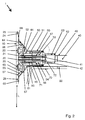
- Fig. 1 shows a perspective view of a heating element 1 for heating a flow channel in a hot runner nozzle, which is for example part of a hot runner tool.
- the heating element 1 has a tubular carrier element 10, which carries a heating conductor 20 with a first connecting pin 21 and a second connecting pin 22.
- it has a connection device 30 with a electrical connection cable 40 having a first and second conductors 41, 42, wherein the first and second connection pin 21, 22 terminate in an insulating body 50 of the connection device 30.
- the insulating body 50 is arranged in sections in a receiving sleeve 60 of the connection device 30. He has in this case a neck portion 51 and a base portion 52, wherein the receiving sleeve 60 is supported on the base portion 52 of the insulating body 50.
- the receiving sleeve 60 has with a first end 61 in the direction of the support member 10 is fixed with this first end 61 to the support member 10 and sets the insulating body 50 relative to the support member 10 fixed.
- the receiving sleeve 60 at this first end 61 has two opposite outwardly facing and fastened to the support member 10 feet 64, 65.
- the two feet 64, 65 have opposite in the longitudinal direction L of tubular support member 10 and are firmly bonded to the support member 10, in particular welded or laser welded.
- the receiving sleeve 60 and the support member 10 each consist of a metal.
- the feet 64, 65 are integrally formed monolithically with the receiving sleeve 60.
- the feet 64, 65 are each subdivided into a leg section 66, 67, which is fixed to the receiving sleeve 60, and a resting on the support member 10 support portion 68, 69 which is fixed to the support member 10.
- the feet 64, 65, in particular their leg portions 66, 67 are adapted to the outer contour of the insulating body 50 that they follow the outer contour.
- a first end 61 opposite the second end 62 is formed as a third crimping sleeve 63 and fixed by plastic deformation on the connecting cable 40, in particular its protective jacket 46.
- the receiving sleeve 60 thus extends beyond the insulating body 50 with the second end 62.
- the receiving sleeve 60 from a first and a second sleeve portion 71, 72 formed, which are welded together, wherein the first sleeve portion 71, the first end 61 of the receiving sleeve 60 and the second sleeve portion 72, the third crimping sleeve 63rd
- a fastening means 70 can be seen on the outside of the receiving sleeve 60, on which a thermocouple 80 is fixed.
- the attachment means 70 is a through opening through which the thermocouple is threaded.
- Fig. 2 shows a section through a connection device 30 of a heating element 1.
- the description Fig. 1 also applies to the presentation Fig. 2 to. In the following, therefore, only the additionally recognizable features will be described.
- a heating conductor 20 which is formed by an electrically conductive thick film 23. This is based on a thick-film technique, applied to the support member 10 first insulating layer 24 and is covered with a second layer applied in thick-film technology insulating layer 25. However, the first insulating layer 24 and the second insulating layer 25 have a recess 26 in the region of the feet 64, 65.
- the heating conductor 20 has a first connection pin 21 and a second connection pin 22. These each have a relief loop or bow and are perpendicular to the support element 10 from.
- the first and second connection pins 21, 22 terminate in the insulating body 50, which electrically separates the first connection pin 21 from the second connection pin 22.
- the electrical connection cable 40 has a first and a second conductor 41, 42.
- the first crimping sleeve 44 and on the second conductor 42, the second crimping sleeve 45 is fixed in each case by plastic deformation.
- the insulating body 50 has two through holes 53, 54, wherein in each through hole 53, 54 one of the first and second crimping sleeves 44,45 is arranged.
- the first and second crimp sleeves 44, 45 each have a cylindrical outer and inner circumferential surface, at least before they are deformed.
- the first and second crimp sleeves 44, 45 have an inner bevel 47 at least on the side of the conductors 41, 42.
- the insulating body 50 in two parts from a rearing member 55 which rests on the support member 10, and a head member 56 which on the Support member 10 opposite side adjacent to the rearing member 55 is positioned is formed.
- the connecting pins 21, 22 are flush with the uprising element 55.
- the head element 56 can initially be pushed onto the electrical conductors 41, 42 during assembly, while the uprising element 55 is already fixed to the first sleeve section 71 on the carrier element 10. As soon as the conductors 41, 42 are connected to the first and second crimping sleeves 44, 45, the head element 56 is then pushed to the rearing element 55. The insulating body 50 then projects, in particular with the head element 56, the first and second crimp sleeves 44, 45.
- the second sleeve section 72 can also first be pushed onto the conductors 41, 42 or the connection cable 40 until the first and second crimp sleeves 44, 45 are deformed. Subsequently, the second sleeve portion 72 can then be pushed to the first sleeve portion 71 and connected thereto. He then fixes the head member 56 of the insulator 50th
- FIG. 3 A longitudinal section through an insulating body 50 is shown.
- a through-hole 53 which is composed of a first, a second and a third section A1, A2, A3.
- the sections A1, A2, A3 have two different diameters.
- the first section A1, which is later arranged on the side of the carrier element 10, in particular with a support surface 57, has a larger diameter than the second section A2.
- the second section A2 is arranged between the first and third sections A1, A3.
- the third section A3 has a larger diameter than the second section A2.
- the first and third sections A1, A3 have an equal diameter.
- the insulating body 50 is composed of a rearing element 55, which forms a base portion 52 with the support surface 57, and a head member 56, which forms a neck portion 51.
- the riot element 55 carries the first and second sections A1, A2. It can be postponed if the crimp sleeves are connected to the terminal pins. Subsequently, the Crimphülsen outside of the riot element 55 are connectable with connecting lines before the head element is pushed over the deformation of the crimping sleeve.
- diameters of 1.6 ⁇ 0.10 mm for the first and third sections and of 1.15 + 0.10 / -0.05 mm are suitable for common heating performance in injection molding technology.
- a crimp sleeve with 1.00 mm diameter can be used.
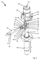
- Fig. 4 shows an exploded perspective view of an injection molding nozzle 100 with a heating element 1.
- the heating element 100 is technically corresponding to the representation in FIG Fig. 1 built up. Therefore, reference is made to the description above with regard to the description of the heating element.
- the sleeve-shaped heating element 1 is pushed onto a material pipe 102 of the injection molding nozzle, which extends in the direction of the longitudinal axis L.
- the heating element 1 is thermally coupled to the material pipe 102 for heating the flow channel 101.
- a clearance fit between the material pipe 102 and the sleeve-shaped heating element 1 is formed at room temperature.
- a press fit should be formed.
- the thermal expansion coefficient of the material tube 102 should be greater than the coefficient of thermal expansion of the heating element 1, in particular of the sleeve-shaped carrier element.
- a housing 103 is provided consisting of a housing head 105 and a housing shaft 106.
- a recess 104 in the form of a lateral longitudinal slot is introduced, which is designed to be open in the direction of the connection device 30.
- the material tube 102 with the heating element 1 is pulled out of the housing shaft 106.
- the heating element 1 is not pushed completely onto the material pipe 102.
- the injection molding nozzle 100 is mounted correctly when the heating element 1 is pushed in the longitudinal direction L in the direction of the housing head 105, so that the connecting device 30 projecting transversely to the longitudinal direction is arranged inside the lateral recess 104 in the housing head 105.
- the housing shaft 106 is to be pushed in the longitudinal direction L in the direction of the housing head 105 until both abut one another with opposite flange edges. With screws 107, the housing shaft 106 and the housing head 105 are then fixed to each other.
- the material tube 102 and the heating element 1 then lie substantially within the housing 103.
- Such an injection molding nozzle can either be connected to a central machine nozzle or a distributor plate, in particular to the housing head 105.
- the housing shaft 106 and the material tube 102 project into a gate opening of a mold plate in which a cavity is formed to form a component (also called form nest).
- connection cable 40 it is in particular possible to electrically connect a grounding conductor of the connection cable 40 with the receiving sleeve 60.
- the grounding conductor of the connection cable 40 can be led out between the two sleeve sections 71, 72 and fixed in an electrically conductive manner on the outside of one of the sleeve sections 71, 72, in particular be lasered.
- heating element 1 in a (also not shown) mold cavity of an injection mold, for example, to heat a portion of the mold cavity wall.
Landscapes
- Engineering & Computer Science (AREA)
- Manufacturing & Machinery (AREA)
- Mechanical Engineering (AREA)
- Injection Moulding Of Plastics Or The Like (AREA)
- Resistance Heating (AREA)
Priority Applications (2)
| Application Number | Priority Date | Filing Date | Title |
|---|---|---|---|
| SI201630667T SI3128806T1 (sl) | 2015-08-03 | 2016-07-26 | Grelni element za pretočni kanal ali votle kalupe in šoba za brizganje s takšnim grelnim elementom |
| PL16181346T PL3128806T3 (pl) | 2015-08-03 | 2016-07-26 | Element grzejny do kanału przepływowego lub gniazdo formy i dysza do formowania wtryskowego z takim elementem grzejnym |
Applications Claiming Priority (1)
| Application Number | Priority Date | Filing Date | Title |
|---|---|---|---|
| DE102015112748.2A DE102015112748A1 (de) | 2015-08-03 | 2015-08-03 | Heizelement für einen Strömungskanal oder ein Formnest und Spritzgießdüse mit einem solchen Heizelement |
Publications (2)
| Publication Number | Publication Date |
|---|---|
| EP3128806A1 true EP3128806A1 (fr) | 2017-02-08 |
| EP3128806B1 EP3128806B1 (fr) | 2020-02-19 |
Family
ID=56851349
Family Applications (1)
| Application Number | Title | Priority Date | Filing Date |
|---|---|---|---|
| EP16181346.4A Active EP3128806B1 (fr) | 2015-08-03 | 2016-07-26 | Élement de chauffage pour un canal d'ecoulement ou une cavite de formage et buse de moulage par injection comprenant un tel element de chauffage |
Country Status (9)
| Country | Link |
|---|---|
| US (1) | US10525624B2 (fr) |
| EP (1) | EP3128806B1 (fr) |
| CN (1) | CN106426835B (fr) |
| CA (1) | CA2936292A1 (fr) |
| DE (1) | DE102015112748A1 (fr) |
| ES (1) | ES2781759T3 (fr) |
| PL (1) | PL3128806T3 (fr) |
| PT (1) | PT3128806T (fr) |
| SI (1) | SI3128806T1 (fr) |
Families Citing this family (1)
| Publication number | Priority date | Publication date | Assignee | Title |
|---|---|---|---|---|
| CN116533455B (zh) * | 2023-05-11 | 2023-11-03 | 湖北正策电气设备有限公司 | 一种用于全自动橡胶射出成型机的电缆插拔头冷流道模具 |
Citations (12)
| Publication number | Priority date | Publication date | Assignee | Title |
|---|---|---|---|---|
| US4403405A (en) * | 1981-07-15 | 1983-09-13 | Gellert Jobst U | Sprue bushing connector assembly method |
| US4486650A (en) | 1981-09-30 | 1984-12-04 | Fusion Plastics Ltd. | Electro-fusion fitting and control apparatus therefor |
| US5235737A (en) * | 1991-12-13 | 1993-08-17 | Gellert Jobst U | Method of making an injection molding nozzle with a heating element extending outward between adjacent collar portions |
| DE19941038A1 (de) | 1999-08-28 | 2001-03-01 | Guenther Heiskanaltechnik Gmbh | Elektrische Heizung für Heißkanalsysteme und Verfahren zur Herstellung einer solchen Heizung |
| US20030218006A1 (en) * | 2002-03-13 | 2003-11-27 | Richard Sutorius | Hot runner heater device and method of manufacture thereof |
| WO2005053361A2 (fr) | 2003-11-25 | 2005-06-09 | Watlow Electric Manufacturing Company | Procede pour fixer un fil de connexion electrique sur un element de surface, et element chauffant, notamment pour un systeme de pulverisation de matiere plastique |
| US20070149049A1 (en) * | 2005-11-25 | 2007-06-28 | Mold-Masters Limited | Injection Molding Component with Low Profile Terminal Connection |
| DE102006049667A1 (de) | 2006-10-18 | 2008-04-24 | Günther Heisskanaltechnik Gmbh | Elektrische Heizeinrichtung für Heißkanalsysteme |
| DE102006049669A1 (de) | 2006-10-18 | 2008-04-24 | Günther Heisskanaltechnik Gmbh | Elektrische Heizeinrichtung für Heißkanalsysteme |
| DE102008004526A1 (de) | 2007-10-25 | 2009-04-30 | Günther Heisskanaltechnik Gmbh | Anschlusseinrichtung |
| DE102008015376A1 (de) | 2008-03-20 | 2009-09-24 | Fraunhofer-Gesellschaft zur Förderung der angewandten Forschung e.V. | Elektrische Verbindung |
| DE102012101400A1 (de) | 2012-02-22 | 2013-09-05 | Günther Heisskanaltechnik Gmbh | Heißkanaldüse mit einem elektrischen Heizelement |
Family Cites Families (13)
| Publication number | Priority date | Publication date | Assignee | Title |
|---|---|---|---|---|
| CA1268616A (fr) * | 1987-10-16 | 1990-05-08 | Mold-Masters Limited | Methode de fabrication de la borne electrique d'une buse de moulage |
| CN1073134A (zh) * | 1991-12-13 | 1993-06-16 | 乔布斯特·乌尔里克·盖勒特 | 一种注塑成型注嘴的制造方法 |
| JPH0724891A (ja) * | 1993-07-13 | 1995-01-27 | Taiho Kogyo Kk | プラスチック射出成形用ホットランナ |
| US5437093A (en) * | 1994-10-11 | 1995-08-01 | Gellert; Jobst U. | Method of making an injection molding nozzle |
| CA2137702C (fr) * | 1994-12-07 | 2004-11-02 | Jobst Ulrich Gellert | Buse pour moulage par injection constituee d'un collier monopiece et d'un corps separables; |
| DE29800473U1 (de) * | 1998-01-13 | 1998-03-19 | Mold-Masters Limited, Georgetown, Ontario | Außenbeheizte Heißkanaldüse mit Heizdraht |
| US6394784B1 (en) * | 2000-03-08 | 2002-05-28 | Mold-Masters Limited | Compact cartridge hot runner nozzle |
| US20020166855A1 (en) * | 2001-05-11 | 2002-11-14 | Renwick Ian J. | Electric heater having dielectric sleeve |
| JP4825572B2 (ja) * | 2006-04-17 | 2011-11-30 | 住友重機械工業株式会社 | トランスファ成形による樹脂封止装置及び樹脂封止方法 |
| DE202007011746U1 (de) * | 2007-08-22 | 2007-10-31 | Günther Heisskanaltechnik Gmbh | Elektrische Heizung zum Erwärmen von im Wesentlichen zylindrischen Objekten |
| DE102009005481B3 (de) * | 2009-01-21 | 2010-04-08 | Bleckmann Gmbh & Co. Kg | Verbindungselement für Heizwendel für Rohrheizkörper sowie Herstellungsverfahren hierfür |
| CN101698320B (zh) * | 2009-10-22 | 2011-12-14 | 杨东佐 | 一种模具加热冷却棒及可实现急冷急热的模具 |
| US8770968B2 (en) * | 2012-04-13 | 2014-07-08 | GM Global Technology Operations LLC | Injection molding tool with embedded induction heater |
-
2015
- 2015-08-03 DE DE102015112748.2A patent/DE102015112748A1/de active Pending
-
2016
- 2016-07-15 CA CA2936292A patent/CA2936292A1/fr not_active Abandoned
- 2016-07-26 EP EP16181346.4A patent/EP3128806B1/fr active Active
- 2016-07-26 PT PT161813464T patent/PT3128806T/pt unknown
- 2016-07-26 ES ES16181346T patent/ES2781759T3/es active Active
- 2016-07-26 PL PL16181346T patent/PL3128806T3/pl unknown
- 2016-07-26 SI SI201630667T patent/SI3128806T1/sl unknown
- 2016-07-29 US US15/223,481 patent/US10525624B2/en active Active
- 2016-08-03 CN CN201610628661.8A patent/CN106426835B/zh active Active
Patent Citations (12)
| Publication number | Priority date | Publication date | Assignee | Title |
|---|---|---|---|---|
| US4403405A (en) * | 1981-07-15 | 1983-09-13 | Gellert Jobst U | Sprue bushing connector assembly method |
| US4486650A (en) | 1981-09-30 | 1984-12-04 | Fusion Plastics Ltd. | Electro-fusion fitting and control apparatus therefor |
| US5235737A (en) * | 1991-12-13 | 1993-08-17 | Gellert Jobst U | Method of making an injection molding nozzle with a heating element extending outward between adjacent collar portions |
| DE19941038A1 (de) | 1999-08-28 | 2001-03-01 | Guenther Heiskanaltechnik Gmbh | Elektrische Heizung für Heißkanalsysteme und Verfahren zur Herstellung einer solchen Heizung |
| US20030218006A1 (en) * | 2002-03-13 | 2003-11-27 | Richard Sutorius | Hot runner heater device and method of manufacture thereof |
| WO2005053361A2 (fr) | 2003-11-25 | 2005-06-09 | Watlow Electric Manufacturing Company | Procede pour fixer un fil de connexion electrique sur un element de surface, et element chauffant, notamment pour un systeme de pulverisation de matiere plastique |
| US20070149049A1 (en) * | 2005-11-25 | 2007-06-28 | Mold-Masters Limited | Injection Molding Component with Low Profile Terminal Connection |
| DE102006049667A1 (de) | 2006-10-18 | 2008-04-24 | Günther Heisskanaltechnik Gmbh | Elektrische Heizeinrichtung für Heißkanalsysteme |
| DE102006049669A1 (de) | 2006-10-18 | 2008-04-24 | Günther Heisskanaltechnik Gmbh | Elektrische Heizeinrichtung für Heißkanalsysteme |
| DE102008004526A1 (de) | 2007-10-25 | 2009-04-30 | Günther Heisskanaltechnik Gmbh | Anschlusseinrichtung |
| DE102008015376A1 (de) | 2008-03-20 | 2009-09-24 | Fraunhofer-Gesellschaft zur Förderung der angewandten Forschung e.V. | Elektrische Verbindung |
| DE102012101400A1 (de) | 2012-02-22 | 2013-09-05 | Günther Heisskanaltechnik Gmbh | Heißkanaldüse mit einem elektrischen Heizelement |
Also Published As
| Publication number | Publication date |
|---|---|
| EP3128806B1 (fr) | 2020-02-19 |
| DE102015112748A1 (de) | 2017-02-09 |
| CN106426835B (zh) | 2021-03-09 |
| SI3128806T1 (sl) | 2020-07-31 |
| CN106426835A (zh) | 2017-02-22 |
| CA2936292A1 (fr) | 2017-02-03 |
| US10525624B2 (en) | 2020-01-07 |
| PL3128806T3 (pl) | 2020-11-02 |
| US20170036383A1 (en) | 2017-02-09 |
| ES2781759T3 (es) | 2020-09-07 |
| PT3128806T (pt) | 2020-03-27 |
Similar Documents
| Publication | Publication Date | Title |
|---|---|---|
| EP3482462B1 (fr) | Élément de contact refroidi par liquide | |
| DE3153393C2 (fr) | ||
| EP2631058B1 (fr) | Buse à canal chaud dotée d'un élément chauffant électrique | |
| DE102015114886B4 (de) | Verfahren zur Herstellung einer Heizvorrichtung für Fluide | |
| DE10112781B4 (de) | Verfahren zum Herstellen einer Glühkerze | |
| DE2148163B2 (de) | Kabelstecker | |
| EP2932566B1 (fr) | Fiche mâle d'auto-chargement | |
| EP3211190B1 (fr) | Systeme de connexion dote d'au moins un connecteur et au moins une conduite de fluide | |
| CH643774A5 (de) | Angussbuchse mit eingebautem elektrischem heizelement fuer eine spritzgussmaschine. | |
| EP3599670A1 (fr) | Douille de connecteur, broche de connecteur et connecteur | |
| DE3427207C2 (fr) | ||
| DE19526582B4 (de) | Beheizte Heißkanaldüse mit Schutzrohren | |
| DE4025993B4 (de) | Eingegossene Sicherung ohne Abschlußkappe | |
| WO2012079738A1 (fr) | Élément de liaison | |
| EP2334139A1 (fr) | Cartouche de chauffage électrique dotée d'une conduite de raccordement | |
| WO2016026671A1 (fr) | Électrode de masse et bougie d'allumage pourvue d'une électrode de masse et procédé de fabrication d'une électrode de masse | |
| EP3128806B1 (fr) | Élement de chauffage pour un canal d'ecoulement ou une cavite de formage et buse de moulage par injection comprenant un tel element de chauffage | |
| DE69319082T2 (de) | Spritzgiessdüse mit einem elektrischen Anschlusselement mit isolierendem Stecker | |
| DE1953302A1 (de) | Elektrisches Kupplungsglied | |
| EP3382255A1 (fr) | Conduite comprenant un raccord et procédé de fonctionnement de ladite conduite | |
| EP1560692B1 (fr) | Element chauffant a poser sur une conduite tubulaire | |
| EP2448369B1 (fr) | Dispositif de raccordement électrique pour l'élément de chauffage électrique d'une buse à canal chaud | |
| DE102014108919A1 (de) | Rohrwendelpatrone | |
| DE102017106220B3 (de) | Aktuator | |
| EP1303020B1 (fr) | Câblage électrique à dispositif d'atténuation de contraintes de traction |
Legal Events
| Date | Code | Title | Description |
|---|---|---|---|
| PUAI | Public reference made under article 153(3) epc to a published international application that has entered the european phase |
Free format text: ORIGINAL CODE: 0009012 |
|
| STAA | Information on the status of an ep patent application or granted ep patent |
Free format text: STATUS: THE APPLICATION HAS BEEN PUBLISHED |
|
| AK | Designated contracting states |
Kind code of ref document: A1 Designated state(s): AL AT BE BG CH CY CZ DE DK EE ES FI FR GB GR HR HU IE IS IT LI LT LU LV MC MK MT NL NO PL PT RO RS SE SI SK SM TR |
|
| AX | Request for extension of the european patent |
Extension state: BA ME |
|
| STAA | Information on the status of an ep patent application or granted ep patent |
Free format text: STATUS: REQUEST FOR EXAMINATION WAS MADE |
|
| 17P | Request for examination filed |
Effective date: 20170808 |
|
| RBV | Designated contracting states (corrected) |
Designated state(s): AL AT BE BG CH CY CZ DE DK EE ES FI FR GB GR HR HU IE IS IT LI LT LU LV MC MK MT NL NO PL PT RO RS SE SI SK SM TR |
|
| RIC1 | Information provided on ipc code assigned before grant |
Ipc: B29C 45/20 20060101ALI20190726BHEP Ipc: B29K 105/00 20060101ALI20190726BHEP Ipc: B29C 45/27 20060101ALI20190726BHEP Ipc: B29C 45/74 20060101ALI20190726BHEP Ipc: H05B 3/42 20060101AFI20190726BHEP Ipc: H05B 3/46 20060101ALI20190726BHEP Ipc: H01R 4/20 20060101ALI20190726BHEP Ipc: H05B 3/08 20060101ALI20190726BHEP |
|
| GRAP | Despatch of communication of intention to grant a patent |
Free format text: ORIGINAL CODE: EPIDOSNIGR1 |
|
| STAA | Information on the status of an ep patent application or granted ep patent |
Free format text: STATUS: GRANT OF PATENT IS INTENDED |
|
| INTG | Intention to grant announced |
Effective date: 20190918 |
|
| GRAS | Grant fee paid |
Free format text: ORIGINAL CODE: EPIDOSNIGR3 |
|
| GRAA | (expected) grant |
Free format text: ORIGINAL CODE: 0009210 |
|
| STAA | Information on the status of an ep patent application or granted ep patent |
Free format text: STATUS: THE PATENT HAS BEEN GRANTED |
|
| AK | Designated contracting states |
Kind code of ref document: B1 Designated state(s): AL AT BE BG CH CY CZ DE DK EE ES FI FR GB GR HR HU IE IS IT LI LT LU LV MC MK MT NL NO PL PT RO RS SE SI SK SM TR |
|
| RAP1 | Party data changed (applicant data changed or rights of an application transferred) |
Owner name: GUENTHER HEISSKANALTECHNIK GMBH |
|
| RIN1 | Information on inventor provided before grant (corrected) |
Inventor name: DROESSLER, RALF Inventor name: SCHNELL, TORSTEN Inventor name: GUENTHER, HERBERT Inventor name: SOMMER, SIEGRID Inventor name: KWIATKOWSKI, MARCO |
|
| REG | Reference to a national code |
Ref country code: CH Ref legal event code: EP |
|
| REG | Reference to a national code |
Ref country code: DE Ref legal event code: R096 Ref document number: 502016008771 Country of ref document: DE |
|
| REG | Reference to a national code |
Ref country code: AT Ref legal event code: REF Ref document number: 1236460 Country of ref document: AT Kind code of ref document: T Effective date: 20200315 |
|
| REG | Reference to a national code |
Ref country code: IE Ref legal event code: FG4D Free format text: LANGUAGE OF EP DOCUMENT: GERMAN |
|
| REG | Reference to a national code |
Ref country code: PT Ref legal event code: SC4A Ref document number: 3128806 Country of ref document: PT Date of ref document: 20200327 Kind code of ref document: T Free format text: AVAILABILITY OF NATIONAL TRANSLATION Effective date: 20200318 |
|
| REG | Reference to a national code |
Ref country code: NL Ref legal event code: FP |
|
| REG | Reference to a national code |
Ref country code: SK Ref legal event code: T3 Ref document number: E 34033 Country of ref document: SK |
|
| PG25 | Lapsed in a contracting state [announced via postgrant information from national office to epo] |
Ref country code: RS Free format text: LAPSE BECAUSE OF FAILURE TO SUBMIT A TRANSLATION OF THE DESCRIPTION OR TO PAY THE FEE WITHIN THE PRESCRIBED TIME-LIMIT Effective date: 20200219 Ref country code: FI Free format text: LAPSE BECAUSE OF FAILURE TO SUBMIT A TRANSLATION OF THE DESCRIPTION OR TO PAY THE FEE WITHIN THE PRESCRIBED TIME-LIMIT Effective date: 20200219 Ref country code: NO Free format text: LAPSE BECAUSE OF FAILURE TO SUBMIT A TRANSLATION OF THE DESCRIPTION OR TO PAY THE FEE WITHIN THE PRESCRIBED TIME-LIMIT Effective date: 20200519 |
|
| REG | Reference to a national code |
Ref country code: LT Ref legal event code: MG4D |
|
| PG25 | Lapsed in a contracting state [announced via postgrant information from national office to epo] |
Ref country code: IS Free format text: LAPSE BECAUSE OF FAILURE TO SUBMIT A TRANSLATION OF THE DESCRIPTION OR TO PAY THE FEE WITHIN THE PRESCRIBED TIME-LIMIT Effective date: 20200619 Ref country code: BG Free format text: LAPSE BECAUSE OF FAILURE TO SUBMIT A TRANSLATION OF THE DESCRIPTION OR TO PAY THE FEE WITHIN THE PRESCRIBED TIME-LIMIT Effective date: 20200519 Ref country code: GR Free format text: LAPSE BECAUSE OF FAILURE TO SUBMIT A TRANSLATION OF THE DESCRIPTION OR TO PAY THE FEE WITHIN THE PRESCRIBED TIME-LIMIT Effective date: 20200520 Ref country code: SE Free format text: LAPSE BECAUSE OF FAILURE TO SUBMIT A TRANSLATION OF THE DESCRIPTION OR TO PAY THE FEE WITHIN THE PRESCRIBED TIME-LIMIT Effective date: 20200219 Ref country code: LV Free format text: LAPSE BECAUSE OF FAILURE TO SUBMIT A TRANSLATION OF THE DESCRIPTION OR TO PAY THE FEE WITHIN THE PRESCRIBED TIME-LIMIT Effective date: 20200219 Ref country code: HR Free format text: LAPSE BECAUSE OF FAILURE TO SUBMIT A TRANSLATION OF THE DESCRIPTION OR TO PAY THE FEE WITHIN THE PRESCRIBED TIME-LIMIT Effective date: 20200219 |
|
| REG | Reference to a national code |
Ref country code: ES Ref legal event code: FG2A Ref document number: 2781759 Country of ref document: ES Kind code of ref document: T3 Effective date: 20200907 |
|
| PG25 | Lapsed in a contracting state [announced via postgrant information from national office to epo] |
Ref country code: EE Free format text: LAPSE BECAUSE OF FAILURE TO SUBMIT A TRANSLATION OF THE DESCRIPTION OR TO PAY THE FEE WITHIN THE PRESCRIBED TIME-LIMIT Effective date: 20200219 Ref country code: SM Free format text: LAPSE BECAUSE OF FAILURE TO SUBMIT A TRANSLATION OF THE DESCRIPTION OR TO PAY THE FEE WITHIN THE PRESCRIBED TIME-LIMIT Effective date: 20200219 Ref country code: DK Free format text: LAPSE BECAUSE OF FAILURE TO SUBMIT A TRANSLATION OF THE DESCRIPTION OR TO PAY THE FEE WITHIN THE PRESCRIBED TIME-LIMIT Effective date: 20200219 Ref country code: LT Free format text: LAPSE BECAUSE OF FAILURE TO SUBMIT A TRANSLATION OF THE DESCRIPTION OR TO PAY THE FEE WITHIN THE PRESCRIBED TIME-LIMIT Effective date: 20200219 Ref country code: RO Free format text: LAPSE BECAUSE OF FAILURE TO SUBMIT A TRANSLATION OF THE DESCRIPTION OR TO PAY THE FEE WITHIN THE PRESCRIBED TIME-LIMIT Effective date: 20200219 |
|
| REG | Reference to a national code |
Ref country code: DE Ref legal event code: R097 Ref document number: 502016008771 Country of ref document: DE |
|
| PLBE | No opposition filed within time limit |
Free format text: ORIGINAL CODE: 0009261 |
|
| STAA | Information on the status of an ep patent application or granted ep patent |
Free format text: STATUS: NO OPPOSITION FILED WITHIN TIME LIMIT |
|
| 26N | No opposition filed |
Effective date: 20201120 |
|
| PG25 | Lapsed in a contracting state [announced via postgrant information from national office to epo] |
Ref country code: MC Free format text: LAPSE BECAUSE OF FAILURE TO SUBMIT A TRANSLATION OF THE DESCRIPTION OR TO PAY THE FEE WITHIN THE PRESCRIBED TIME-LIMIT Effective date: 20200219 |
|
| PG25 | Lapsed in a contracting state [announced via postgrant information from national office to epo] |
Ref country code: IE Free format text: LAPSE BECAUSE OF NON-PAYMENT OF DUE FEES Effective date: 20200726 |
|
| PGFP | Annual fee paid to national office [announced via postgrant information from national office to epo] |
Ref country code: TR Payment date: 20210716 Year of fee payment: 6 Ref country code: SI Payment date: 20210716 Year of fee payment: 6 Ref country code: SK Payment date: 20210723 Year of fee payment: 6 |
|
| PG25 | Lapsed in a contracting state [announced via postgrant information from national office to epo] |
Ref country code: MT Free format text: LAPSE BECAUSE OF FAILURE TO SUBMIT A TRANSLATION OF THE DESCRIPTION OR TO PAY THE FEE WITHIN THE PRESCRIBED TIME-LIMIT Effective date: 20200219 Ref country code: CY Free format text: LAPSE BECAUSE OF FAILURE TO SUBMIT A TRANSLATION OF THE DESCRIPTION OR TO PAY THE FEE WITHIN THE PRESCRIBED TIME-LIMIT Effective date: 20200219 |
|
| PG25 | Lapsed in a contracting state [announced via postgrant information from national office to epo] |
Ref country code: MK Free format text: LAPSE BECAUSE OF FAILURE TO SUBMIT A TRANSLATION OF THE DESCRIPTION OR TO PAY THE FEE WITHIN THE PRESCRIBED TIME-LIMIT Effective date: 20200219 Ref country code: AL Free format text: LAPSE BECAUSE OF FAILURE TO SUBMIT A TRANSLATION OF THE DESCRIPTION OR TO PAY THE FEE WITHIN THE PRESCRIBED TIME-LIMIT Effective date: 20200219 |
|
| PGFP | Annual fee paid to national office [announced via postgrant information from national office to epo] |
Ref country code: ES Payment date: 20220928 Year of fee payment: 7 Ref country code: CZ Payment date: 20220718 Year of fee payment: 7 |
|
| PGFP | Annual fee paid to national office [announced via postgrant information from national office to epo] |
Ref country code: PL Payment date: 20220718 Year of fee payment: 7 |
|
| REG | Reference to a national code |
Ref country code: SK Ref legal event code: MM4A Ref document number: E 34033 Country of ref document: SK Effective date: 20220726 |
|
| REG | Reference to a national code |
Ref country code: SI Ref legal event code: KO00 Effective date: 20230314 |
|
| PG25 | Lapsed in a contracting state [announced via postgrant information from national office to epo] |
Ref country code: SK Free format text: LAPSE BECAUSE OF NON-PAYMENT OF DUE FEES Effective date: 20220726 Ref country code: SI Free format text: LAPSE BECAUSE OF NON-PAYMENT OF DUE FEES Effective date: 20220727 |
|
| PGFP | Annual fee paid to national office [announced via postgrant information from national office to epo] |
Ref country code: IT Payment date: 20230724 Year of fee payment: 8 Ref country code: CH Payment date: 20230801 Year of fee payment: 8 Ref country code: AT Payment date: 20230720 Year of fee payment: 8 |
|
| PG25 | Lapsed in a contracting state [announced via postgrant information from national office to epo] |
Ref country code: CZ Free format text: LAPSE BECAUSE OF NON-PAYMENT OF DUE FEES Effective date: 20230726 |
|
| PGFP | Annual fee paid to national office [announced via postgrant information from national office to epo] |
Ref country code: LU Payment date: 20240719 Year of fee payment: 9 |
|
| REG | Reference to a national code |
Ref country code: ES Ref legal event code: FD2A Effective date: 20240830 |
|
| PGFP | Annual fee paid to national office [announced via postgrant information from national office to epo] |
Ref country code: NL Payment date: 20240719 Year of fee payment: 9 |
|
| PG25 | Lapsed in a contracting state [announced via postgrant information from national office to epo] |
Ref country code: TR Free format text: LAPSE BECAUSE OF NON-PAYMENT OF DUE FEES Effective date: 20220726 |
|
| PGFP | Annual fee paid to national office [announced via postgrant information from national office to epo] |
Ref country code: DE Payment date: 20240731 Year of fee payment: 9 |
|
| PGFP | Annual fee paid to national office [announced via postgrant information from national office to epo] |
Ref country code: GB Payment date: 20240725 Year of fee payment: 9 Ref country code: PT Payment date: 20240718 Year of fee payment: 9 |
|
| PGFP | Annual fee paid to national office [announced via postgrant information from national office to epo] |
Ref country code: BE Payment date: 20240719 Year of fee payment: 9 |
|
| PGFP | Annual fee paid to national office [announced via postgrant information from national office to epo] |
Ref country code: FR Payment date: 20240730 Year of fee payment: 9 |