EP3128689B1 - Ansteuerungseinheit für elektrischen fader, tonmischer und ansteuerungsverfahren für elektrischen fader - Google Patents
Ansteuerungseinheit für elektrischen fader, tonmischer und ansteuerungsverfahren für elektrischen fader Download PDFInfo
- Publication number
- EP3128689B1 EP3128689B1 EP16182593.0A EP16182593A EP3128689B1 EP 3128689 B1 EP3128689 B1 EP 3128689B1 EP 16182593 A EP16182593 A EP 16182593A EP 3128689 B1 EP3128689 B1 EP 3128689B1
- Authority
- EP
- European Patent Office
- Prior art keywords
- drive power
- fader
- electric fader
- target position
- electric
- Prior art date
- Legal status (The legal status is an assumption and is not a legal conclusion. Google has not performed a legal analysis and makes no representation as to the accuracy of the status listed.)
- Active
Links
Images




Classifications
-
- G—PHYSICS
- G05—CONTROLLING; REGULATING
- G05D—SYSTEMS FOR CONTROLLING OR REGULATING NON-ELECTRIC VARIABLES
- G05D3/00—Control of position or direction
- G05D3/12—Control of position or direction using feedback
-
- H—ELECTRICITY
- H04—ELECTRIC COMMUNICATION TECHNIQUE
- H04H—BROADCAST COMMUNICATION
- H04H60/00—Arrangements for broadcast applications with a direct linking to broadcast information or broadcast space-time; Broadcast-related systems
- H04H60/02—Arrangements for generating broadcast information; Arrangements for generating broadcast-related information with a direct linking to broadcast information or to broadcast space-time; Arrangements for simultaneous generation of broadcast information and broadcast-related information
- H04H60/04—Studio equipment; Interconnection of studios
-
- F—MECHANICAL ENGINEERING; LIGHTING; HEATING; WEAPONS; BLASTING
- F21—LIGHTING
- F21V—FUNCTIONAL FEATURES OR DETAILS OF LIGHTING DEVICES OR SYSTEMS THEREOF; STRUCTURAL COMBINATIONS OF LIGHTING DEVICES WITH OTHER ARTICLES, NOT OTHERWISE PROVIDED FOR
- F21V33/00—Structural combinations of lighting devices with other articles, not otherwise provided for
- F21V33/0004—Personal or domestic articles
- F21V33/0052—Audio or video equipment, e.g. televisions, telephones, cameras or computers; Remote control devices therefor
- F21V33/0056—Audio equipment, e.g. music instruments, radios or speakers
-
- H—ELECTRICITY
- H05—ELECTRIC TECHNIQUES NOT OTHERWISE PROVIDED FOR
- H05B—ELECTRIC HEATING; ELECTRIC LIGHT SOURCES NOT OTHERWISE PROVIDED FOR; CIRCUIT ARRANGEMENTS FOR ELECTRIC LIGHT SOURCES, IN GENERAL
- H05B47/00—Circuit arrangements for operating light sources in general, i.e. where the type of light source is not relevant
- H05B47/10—Controlling the light source
- H05B47/165—Controlling the light source following a pre-assigned programmed sequence; Logic control [LC]
-
- H—ELECTRICITY
- H05—ELECTRIC TECHNIQUES NOT OTHERWISE PROVIDED FOR
- H05B—ELECTRIC HEATING; ELECTRIC LIGHT SOURCES NOT OTHERWISE PROVIDED FOR; CIRCUIT ARRANGEMENTS FOR ELECTRIC LIGHT SOURCES, IN GENERAL
- H05B47/00—Circuit arrangements for operating light sources in general, i.e. where the type of light source is not relevant
- H05B47/10—Controlling the light source
- H05B47/17—Operational modes, e.g. switching from manual to automatic mode or prohibiting specific operations
-
- F—MECHANICAL ENGINEERING; LIGHTING; HEATING; WEAPONS; BLASTING
- F21—LIGHTING
- F21W—INDEXING SCHEME ASSOCIATED WITH SUBCLASSES F21K, F21L, F21S and F21V, RELATING TO USES OR APPLICATIONS OF LIGHTING DEVICES OR SYSTEMS
- F21W2131/00—Use or application of lighting devices or systems not provided for in codes F21W2102/00-F21W2121/00
- F21W2131/40—Lighting for industrial, commercial, recreational or military use
- F21W2131/406—Lighting for industrial, commercial, recreational or military use for theatres, stages or film studios
-
- Y—GENERAL TAGGING OF NEW TECHNOLOGICAL DEVELOPMENTS; GENERAL TAGGING OF CROSS-SECTIONAL TECHNOLOGIES SPANNING OVER SEVERAL SECTIONS OF THE IPC; TECHNICAL SUBJECTS COVERED BY FORMER USPC CROSS-REFERENCE ART COLLECTIONS [XRACs] AND DIGESTS
- Y02—TECHNOLOGIES OR APPLICATIONS FOR MITIGATION OR ADAPTATION AGAINST CLIMATE CHANGE
- Y02D—CLIMATE CHANGE MITIGATION TECHNOLOGIES IN INFORMATION AND COMMUNICATION TECHNOLOGIES [ICT], I.E. INFORMATION AND COMMUNICATION TECHNOLOGIES AIMING AT THE REDUCTION OF THEIR OWN ENERGY USE
- Y02D30/00—Reducing energy consumption in communication networks
- Y02D30/70—Reducing energy consumption in communication networks in wireless communication networks
Definitions
- Some preferred embodiments of the present invention relate to an electric fader drive unit that drives an electric fader of a light dimmer, an audio mixer, or the like.
- a light dimmer used in a stage or a studio is capable of controlling the brightness of lighting by adjustment of the position of a fader of the light dimmer.
- an audio mixer used in a stage or a studio is capable of adjusting volume, a tone, or the like, by adjustment of the position of a fader of the audio mixer.
- Some light dimmers or some audio mixers include an electric fader.
- the electric fader includes a fader, a motor, and a belt that moves the fader.
- An electric fader drive unit including such an electric fader when receiving an indication of a target position, drives the electric fader and moves the fader to the target position.
- the electric fader is required to move to the target position smoothly and accurately.
- the speed of operation needs to be a comparatively low speed.
- the electric fader needs to be driven with comparatively low drive power.
- the electric fader has an individual difference or a change over the years. Accordingly, when driven with low drive power, the electric fader may not obtain a sufficient drive power and may stop before reaching the target position. In order to prevent the influence of such an individual difference and a change over the years, it is necessary to set the drive power to be comparatively high. However, when driven with comparatively high drive power, the electric fader may stop at a position beyond the target position (overshoot may occur).
- an electric fader drive unit disclosed in JP 2684808 B performs control of significantly reducing drive power if an electric fader in a current position approaches a target position.
- an electric fader drive unit disclosed in JP 3775368 B controls drive power so that the movement speed of a fader does not exceed a predetermined movement speed.
- GB 2 263 049 A discloses a so-called moving fader which is used acting as a so-called mixer.
- the mixer sound mixing apparatus
- PA system public address system
- PA system that is, in general, a sound amplifier in which a plurality of input sounds are processed simultaneously in parallel
- the moving fader has especially added and advanced functions.
- the position of a so-called fader (general level controller) is controlled by means of a motor controlled by an automatic controlling means such as a microcomputer.
- the fader is a part of an input-channel-process device employed by the moving fader.
- US 6,153,994 A discloses a control console comprising at least one member for adjusting the level of radio-electric signals capable of taking up any position between two extreme positions, elements for detecting the instantaneous position of the member and elements for memorizing at least one position of the member.
- Each adjusting member is provided with both motor mechanism for automatically positioning the adjusting member in its memorized position corresponding to a status of adjustment selected by the user and tactile elements for signalling the deviation ratio of the adjusting member relative to its predetermined memorized position.
- US 5, 122, 720 A discloses a moving fader system, primarily for the processing and combining of audio signals, which includes a dedicated preprocessor to implement the execution of repetious input instructions.
- Other features contributing to the operation of the system include "Look-up Tables" included in the preprocessor for conversion purposes, a fiberoptic link for transmission of digital signals between the preprocessor and the servo circuits associated with each fader assembly, and circuitry for combining the outputs of a position digital-to-analog (D/A) converter, an offset correction D/A converter and a gain correction D/A converter, to provide accurate analog servo signals to each fader assembly.
- D/A position digital-to-analog
- the sound generated by the electric fader drive unit may become a noise that has a bad influence on the surrounding environment. For example, since the sound can be easily heard in a quiet studio, the sound generated by the electric fader drive unit is perceived as a noise.
- the present invention provides an electric fader drive unit as set forth in claim 1, a fader device as set forth in claim 12, an audio mixer as set forth in claim 13, and an electric fader driving method as set forth in claim 14, that are in consideration of a balance between increase in speed and decrease in noise .
- Preferred embodiments of the present invention may be gathered from the dependent claims.
- the electric fader drive unit is capable of performing control in consideration of a balance between increase in speed and decrease in noise.
- Fig. 1 is a functional block diagram showing a configuration of an electric fader drive unit 1.
- the electric fader drive unit 1 performs control of moving a fader at a position in an electric fader 2 to a target position.
- the electric fader drive unit 1 and the electric fader 2 configure a fader device 5.
- Fig. 6A is a perspective view showing an example of a configuration of the electric fader 2.
- Fig. 6B is an exploded view showing an example of the configuration of the electric fader 2.
- the electric fader 2 mainly includes a frame body 101, a motor 102, a driving pulley 103, a movable member 104, a driven pulley 105, a belt 106, a fader 107, a variable resistor 108, and a spacer 110.
- the frame body 101 is made of metal plates.
- the motor 102 is attached to the first end of the frame body 101.
- the driving pulley 103 and the spacer 110 are joined with a rotary shaft of the motor 102.
- the movable member 104 is arranged at the second end of the frame body 101.
- the driven pulley 105 is pivotally supported on the movable member 104.
- the belt 106 has an annular shape.
- the belt 106 is stretched between the driving pulley 103 and the driven pulley 105.
- the fader 107 is joined with the belt 106. As the motor 102 rotates, the belt 106 moves, so that the fader 107 moves in the longitudinal direction of the frame body 101.
- the variable resistor 108 adjusts a resistance value with the movement of the fader 107.
- the frame body 101 is formed by punching and then bending a metal plate.
- the frame body 101 has a flat plate-like portion 101a in the center.
- the plate-like portion 101a has two side walls 101b that are perpendicular to the plate-like portion 101a and face each other, on a first side portion and a second side portion in the longitudinal direction.
- a bridge portion 101c is provided on the opposite sides of the upper face of the side walls 101b.
- the bridge portion 101c has a round hole 101d.
- the plate-like portion 101a includes, in the center, a substantially rectangular long window hole 101e in the longitudinal direction.
- the variable resistor 108 includes a lever 114a that is inserted into the long window hole 101e. This enables the lever 114a to move in the longitudinal direction.
- a guide portion 104c is pressed against the side walls 101b of the frame body 101 when a screw 112 is fastened. Accordingly, the movable member 104 may become difficult to move and is fixed to the frame body 101
- the lever 114a has a rectangle hole with which a rectangular lever supporting portion 107b protruded from the central part of the fader 107 is engaged. Accordingly, the fader 107 is connected with the lever 114a. The fader 107 and the lever 114a move together. It is to be noted that the frame body 101 and the variable resistor 108 are integrally engaged with each other.
- the lever 114a includes a not-shown knob fixed onto the upper part of the lever 114a. The knob, the fader 107, and the lever 114a configure a fader. If a user holds the knob and moves the lever 114a manually along the long window hole 101e, the resistance value of the variable resistor 108 is adjusted.
- the variable resistor 108 includes a metal casing 113 and a shaft 113a.
- the metal casing 113 is formed into a box shape by bending a metal plate and the like.
- the shaft 113a is made of a pair of metal bars bridging in the longitudinal direction in the metal casing 113.
- the shaft 113a holds a belt-like resistor and a current collector that are not shown.
- the electric fader drive unit 1 includes a fader position control portion 11, an electric fader control portion 12, a drive portion 13, a position detection portion 14, a CPU (Central Processing Unit) 15, and a storage portion 17.
- a fader position control portion 11 an electric fader control portion 12
- a drive portion 13 a position detection portion 14
- a CPU Central Processing Unit
- the CPU 15 is a control portion that performs integrated control on the operation of the electric fader drive unit 1.
- the CPU 15 executes a predetermined program stored in the storage portion (storage medium) 17 such as a memory.
- the electric fader 2 is included in a light dimmer, a digital mixer, or the like.
- the preferred embodiments described below shows a configuration in which a digital mixer includes the electric fader 2 and the electric fader drive unit 1.
- the CPU 15 is mounted in the digital mixer.
- the light dimmer is capable of adjusting the brightness of lighting.
- the digital mixer is mainly capable of adjusting levels, performing equalizing, or imparting an effect.
- the fader position control portion 11 indicates a target position of the fader 107 in the electric fader 2.
- the position of the electric fader 2 means the position of the fader 107 in the electric fader 2.
- the operation of moving the electric fader 2 means the operation of moving the fader 107 in the electric fader 2.
- the fader position control portion 11, the electric fader control portion 12, and the drive portion 13 are hardware other than the CPU 15.
- the fader position control portion 11, the electric fader control portion 12, and the drive portion 13 may be software.
- the CPU 15 is capable of achieving by software a configuration of the fader position control portion 11, the electric fader control portion 12, and the drive portion 13 by executing a predetermined program.
- a user by holding a knob 2a included in the electric fader 2, can move the electric fader 2 to a target position.
- the user can also cause the storage portion 17 of the electric fader drive unit 1 to store the current position of the electric fader 2 as one scene. If the user gives an instruction of reading a scene stored in the past (scene recall), the fader position control portion 11 indicates the target position of the electric fader 2.
- the scene stored in the storage portion 17 includes data (position data) that indicates the position of the electric fader.
- position data indicates the position of the electric fader.
- the CPU 15 may indicate the movement speed of the electric fader 2.
- the fader position control portion 11, unless the maximum movement speed is indicated, sets a plurality of target positions before a final target position indicated in the target position data.
- the fader position control portion 11 outputs data that indicates a new target position to the electric fader control portion 12 whenever a predetermined time elapses.
- the predetermined time is controlled by the CPU 15. In a case in which the predetermined time is short, the movement speed of the electric fader 2 becomes fast, and in a case in which the predetermined time is long, the movement speed of the electric fader 2 becomes slow.
- the electric fader control portion 12 generates drive information for causing the electric fader 2 to move to the target position inputted from the fader position control portion 11, and supplies the drive information to the drive portion 13.
- the drive portion 13 drives the electric fader 2 based on supplied drive information.
- the digital mixer includes a display device (not shown) that displays the screen of a user interface (UI) for setting the position of the fader.
- UI user interface
- the fader position control portion 11 generates data that indicates a target position corresponding to inputted setting position information I, and outputs the data that indicates a target position to the electric fader control portion 12. Accordingly, the electric fader 2 is moved to the target position corresponding to the setting position information I. In other words, if the user specifies the position of the fader on the UI screen, the electric fader 2 moves to the specified position.
- the digital mixer may store sequence data.
- the sequence data includes an event of a scene recall operation (or a fader operation event) and a time stamp that indicates the time when the event is generated.
- the fader position control portion 11 When this sequence data is reproduced, the fader position control portion 11 generates data that indicates a target position corresponding to the fader operation event, and outputs the data to the electric fader control portion 12. Accordingly, whenever time reaches the time of a fader movement event indicated by the time stamp, the electric fader 2 is moved to a position corresponding to the fader movement event.
- Fig. 1 illustrates only one electric fader 2
- a plurality of electric faders 2 are mounted in the digital mixer.
- the fader position control portion 11 generates data that indicates a target position of the electric fader 2 and data that indicates an operation mode based on the control of the CPU 15.
- the generated data that indicates a target position and the generated data that indicates an operation mode are outputted to the electric fader control portion 12.
- the operation mode includes a "high speed movement mode” in which the electric fader 2 is driven at a high speed and is moved to a target position, and a “silent movement mode” in which the electric fader 2 is driven silently and is moved to a target position.
- the data that indicates an operation mode includes information that specifies one of the operation modes.
- the fader position control portion 11 changes the operation mode to be specified according to the difference (distance to move the electric fader) between the current position of the electric fader 2 and the target position.
- the current position of the electric fader 2 is notified from the position detection portion 14 to the fader position control portion 11.
- the electric fader control portion 12 when receiving the data that indicates a target position and the data that indicates an operation mode from the fader position control portion 11, operates in the specified operation mode.
- the electric fader control portion 12 calculates the remaining distance that is a difference between the current position of the electric fader 2 detected by the position detection portion 14 and the supplied target position. Then, the electric fader control portion 12 generates drive information corresponding to the calculated difference and the set operation mode. The electric fader control portion 12 outputs the generated drive information to the drive portion 13.
- the drive portion 13 generates a drive signal according to the inputted drive information.
- the drive portion 13 applies the generated drive signal to the electric fader 2 and drives the motor 102.
- the knob 2a is moved toward the target position.
- the current position of the electric fader 2 during movement is detected by the position detection portion 14, and is fed back to the electric fader control portion 12.
- the electric fader control portion 12, the drive portion 13, the electric fader 2, and the position detection portion 14 configure a feedback loop.
- the electric fader control portion 12, the drive portion 13, the electric fader 2, and the position detection portion 14, by the feedback loop perform servo control so that the remaining distance may become zero. Accordingly, the electric fader 2 is moved to the target position.
- the fader position control portion 11 when generating a target position, sends data that indicates the high speed movement mode to the electric fader control portion 12 in a case in which a distance to move the electric fader, that is, a difference between the current position and the target position, is large.
- the electric fader control portion 12 that has been set in the high speed movement mode supplies the drive information for driving the electric fader 2 with below-described base drive power to the drive portion 13.
- the electric fader 2 driven with the base drive power moves at a high speed and reaches the target position.
- the drive power to be set by the electric fader control portion 12 includes minimum drive power Pmin that is the lowest drive power capable of moving the electric fader 2, maximum drive power Pmax that is the highest drive power, the base drive power that is much higher than the minimum drive power Pmin and is lower than the maximum drive power Pmax, and silent drive power that is higher than the minimum drive power Pmin and is lower than the base drive power.
- the fader position control portion 11 when generating a target position, sends data that indicates the silent movement mode to the electric fader control portion 12 in a case in which the distance to move the electric fader, that is the difference between the current position and the target position is not large. Accordingly, the electric fader control portion 12 set in the silent movement mode supplies the drive information for driving the electric fader 2 with the silent drive power to the drive portion 13.
- the electric fader 2 driven with the silent drive power moves silently, and reaches the target position.
- the electric fader drive unit 1 by switching the operation modes according to the length of the distance to move the electric fader between the current position and the target position, performs movement control in consideration of a balance between increase in speed and decrease in noise.
- the operation mode automatically switches according to the distance to move the electric fader from a current position to a target position, a user does not need to be conscious of the operation mode. It is preferable that the distance required for switching the operation modes should be about five mm to about 15 mm. In other words, a value from about five mm to about 15 mm is set to be a threshold value for switching the operation modes of the high speed movement mode and the silent movement mode. In addition, the operation modes are not switched during the movement of the electric fader 2.
- Fig. 2 is a diagram showing a configuration of the drive portion 13.
- the drive portion 13 includes a pattern waveform generation portion 21, and an AND gate 22, and a drive circuit 23.
- the pattern waveform generation portion 21 generates a pattern waveform corresponding to the drive information supplied from the electric fader control portion 12.
- the drive information includes data that indicates a direction in which the electric fader 2 is driven, data that indicates drive power, and an ON/OFF signal for driving.
- the pattern waveform generation portion 21 generates a drive signal that drives the motor according to the indicated drive power.
- the pattern waveform generation portion 21 is a PWM (Pulse Width Modulation) circuit.
- the PWM circuit outputs as a drive signal a pulse waveform of a duty ratio corresponding to the data that indicates drive power.
- the PWM circuit is a circuit that changes a duty cycle of a predetermined pulse width (a ratio between H level and L level of the pulse width) according to the magnitude of the indicated drive power, at a predetermined cycle and drives the motor of the electric fader 2. While a pulse is ON (H level), a substantially the same voltage as a power supply voltage is applied to the motor. While the pulse is OFF (L level), no electric power is supplied to the motor. Therefore, while the pulse is off, the average electric power is decreased. In other words, the pattern waveform generation portion 21 controls energy supplied to the motor by performing PWM modulation of the pulse width.
- the drive signal of a PWM waveform generated in the pattern waveform generation portion 21 is inputted into the first input portion of the AND gate 22.
- the ON/OFF signal for driving supplied from the electric fader control portion 12 is supplied to the second input portion of the AND gate 22.
- the electric fader control portion 12 generates an ON signal while the electric fader 2 is driven.
- the drive circuit 23 is a circuit that outputs a drive signal of the electric power that drives the motor 102 of the electric fader 2.
- the drive circuit 23 changes the direction of current (voltage) according to the data that indicates the direction supplied from the electric fader control portion 12, and outputs a drive signal.
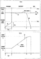
- Fig. 3A is a view showing a drive signal D in the high speed movement mode.
- Fig. 3B is a view showing a position of the electric fader 2 in the high speed movement mode. It is to be noted that, while the drive signal D is generated by the drive portion 13, the drive signal D is assumed to be generated by the electric fader control portion 12 since the drive signal D is generated according to the drive information from the electric fader control portion 12.
- the fader position control portion 11 when having generated a target position F1, specifies the high speed movement mode when the distance between the target position F1 and the current position Fc1 of the electric fader 2 is not less than a predetermined value.
- the electric fader control portion 12 is set to be in the high speed movement mode. To begin with, the electric fader control portion 12 generates a drive signal D1 of "precharge" in which drive power increases gradually from the time t0 to time t1.
- the drive signal D1 increases in proportion to the lapse of time during a first predetermined time Tpre from the time t0 to the time t1.
- the drive power is, from the state of zero, maintained at the preparation drive power that is less than minimum drive power Pmin.
- the preparation drive power increases up to a preliminary prepared drive power Ppre. Accordingly, tension to such an extent that the electric fader 2 is not moved is applied mainly to the motor 102 of the electric fader 2.
- the electric fader drive unit 1 when thereafter applying the drive signal D not less than the minimum drive power Pmin to the electric fader 2, is capable of significantly reducing a noise that gives a bad influence on the surrounding environment.
- the first predetermined time Tpre for which the drive signal D1 of the "precharge” is applied is at least 10 ms.
- the first predetermined time Tpre may preferably be from 30 ms to 40 ms.
- the preliminary preparation drive power Ppre of the "precharge” may preferably be about 80% to 100% of the minimum drive power Pmin. It is to be noted that the preliminary preparation drive power Ppre, even if being set as about 30% to about 80% of the minimum drive power Pmin, may obtain some effect of making an operation sound silent.
- the electric fader 2 includes various kinds of machine components provided with an "allowance" of space and the like.
- a noise is generated.
- the belt 106 has some bending. In a case in which the drive power is suddenly applied to the belt 106, the belt 106 expands and contracts, which generates a noise.
- the electric fader drive unit 1 performs the precharge so as to cause a large tension to be gradually imposed on the various kinds of the components of the electric fader 2. Therefore, the various kinds of the components of the electric fader 2 contact each other without generating a noise and a large tension is gradually imposed on the belt 106. In this way, since the electric fader 2 is driven after a certain amount of tension is imposed on the various kinds of the components, the electric fader 2 starts moving with a silent operation sound.
- the precharge ends at the time t1.
- the electric fader control portion 12 shifts into a movement period if the time t1 passes.
- the electric fader control portion 12 generates a drive signal D2 of base drive power Pb at the time t1, and performs primary driving.
- the drive power increases immediately from the preliminary preparation drive power Ppre to the base drive power Pb.
- the drive power may increase, within an extremely short time, from the preliminary preparation drive power Ppre to the base drive power Pb.
- the electric fader control portion 12 is capable of detecting the current position and the movement speed of the electric fader 2.
- the electric fader control portion 12 performs control of slightly increasing or decreasing the base drive power Pb so that the movement speed of the electric fader 2 may become a predetermined target speed set in the high speed movement mode. Such control is performed in the above-stated feedback loop. As shown in Fig. 3A , the base drive power Pb is increased or decreased between Pb1 and Pb2 according to the current movement speed. Thus, the movement speed is controlled to be the target speed.
- the electric fader control portion 12 decreases the drive power in a case in which the calculated difference (distance) between the current position and the target position F1 is not more than a predetermined distance L1.
- the calculated difference (distance) between the current position and the target position F1 is not more than the predetermined distance L1 at time t2. Therefore, the electric fader control portion 12, from the time t2 to time t3, generates a drive signal D3 for decreasing the drive power from the base drive power Pb to zero.
- the electric fader 2 receives a braking force caused by a frictional force, which decreases the movement speed of the electric fader 2. Then, the electric fader 2, as shown in Fig. 3B , reaches the target position F1 at the time t3 and stops.
- the distance L1 may preferably be about 10 mm to about 20 mm. The distance L1 may preferably be short when the electric fader 2 is relatively heavy and may preferably be long when the electric fader 2 is light.
- the electric fader control portion 12 performs the control of moving the electric fader 2 in the opposite direction.
- the electric fader 2 may overshoot in the opposite direction again. In such a case, the electric fader 2 vibrates and generates an unusual sound.
- the upper limit value of the number of retry times should be determined.
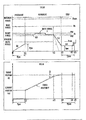
- Fig. 4A is a view showing a drive signal D in the silent movement mode.
- Fig. 4B is a view showing a position of the electric fader 2 in the silent movement mode. It is to be noted that, while the drive signal D is generated by the drive portion 13, the drive signal D is assumed to be generated by the electric fader control portion 12 since the drive signal D is generated according to the drive information from the electric fader control portion 12.
- the fader position control portion 11 when having generated a target position F2, specifies the silent movement mode when the distance between the target position F2 and the current position Fc2 of the electric fader 2 is less than a predetermined value.
- the electric fader control portion 12 is set to be in the silent movement mode.
- the electric fader control portion 12 generates the drive signal D1 of the above-stated precharge from the time t0 to time t11.
- the precharge ends at the time t11.
- the electric fader control portion 12 shifts to a movement period if the time t11 passes .
- the electric fader control portion 12 generates a drive signal D12 of silent drive power Ps lower than the base drive power Pb at the time t11, and performs primary driving.
- the drive power increases immediately from the preliminary preparation drive power Ppre to the silent drive power Ps.
- the drive power may increase, within an extremely short time, from the preliminary preparation drive power Ppre to the silent drive power Ps.
- the electric fader control portion 12 performs control of slightly increasing or decreasing the silent drive power Ps so that the movement speed of the electric fader 2 may become a predetermined target speed set in the silent movement mode. This control is performed in the above-mentioned feedback loop. As shown in Fig. 4A , the silent drive power Ps is increased or decreased between Ps1 and Ps2 according to the current movement speed. Accordingly, the movement speed is controlled to be the target speed.
- the electric fader control portion 12 decreases the drive power when the calculated difference (distance) between the current position and the target position F2 is not more than a predetermined distance L2.
- the electric fader control portion 12 from the time t12 to time t13, generates a drive signal D13 for decreasing the drive power from the silent drive power Ps to the preparation drive power.
- the preparation drive power is set as post preparation drive power Ppos that has a value lower than the preliminary preparation drive power Ppre.
- the post preparation drive power Ppos may have a value higher than the preliminary preparation drive power Ppre or may have the same value as the preliminary preparation drive power Ppre.
- the decrease in the drive power of the drive signal D13 is more gradual than the decrease in the drive power of the drive signal D3.
- the electric fader 2 receives a braking force caused by a frictional force, which decreases the movement speed of the electric fader 2. Then, the electric fader 2, as shown in Fig. 4B , reaches the target position F2 at the time t13 and stops.
- the distance L2 may preferably be about 10 mm to about 20 mm. The distance L2 may preferably be short when the electric fader 2 is relatively heavy and may preferably be long when the electric fader 2 is light.
- the electric fader control portion 12 even after the time t13 passes, generates a drive signal D14 so that the drive power may be maintained at the post preparation drive power Ppos.
- the drive signal D14 is referred to as "drive signal of postcharge”.
- the "postcharge” refers to a state in which, after the primary driving in which the electric fader 2 is moved to a target position, the post preparation drive power Ppos lower than the minimum drive power Pmin is continuously applied to the drive portion of the electric fader 2 over a second predetermined time Tpost and the tension lower than the minimum drive power is continuously imposed on the drive portion of the electric fader 2.
- the electric fader control portion 12 in a case in which the following primary driving is not performed within the second predetermined time Tpost, stops the postcharge at a time when the second predetermined period Tpost elapses (at time t15).
- the electric fader control portion 12 in a case in which a following target value and a following operation mode are indicated at time t14 before reaching the time t15, at the time t14, generates a drive signal D1' having the same inclination (proportionality coefficient) as the drive signal D1 until the drive power reaches the preliminary preparation drive power Ppre.
- the electric fader control portion 12 generates a drive signal of the primary driving corresponding to the indicated operation mode after the drive power reaches the preliminary preparation drive power Ppre.
- the second predetermined time Tpost in which the drive signal D14 of the postcharge is applied may preferably be from several 10 ms to several 100 ms.
- the several 10 ms to the several 100 ms may be from 20 ms to 300 ms, for example.
- the second predetermined time Tpost may preferably be about 50 ms. If the second predetermined time Tpost is too long, it will become difficult for a user to operate the electric fader 2 manually.
- the electric fader control portion 12 may stop the postcharge when detecting a user touch on the electric fader 2.
- the electric fader drive unit 1 is capable of detecting the user touch on the electric fader 2, by including the electric fader 2 provided with a touch sensor.
- the post preparation drive power Ppos should be about 30% to 50% of the minimum drive power Pmin.
- the post preparation drive power Ppos even if being about 50% to 100% of the minimum drive power Pmin, has an effect of making an operation sound silent.
- the accuracy of making a stop at a target position is increased in a case in which the post preparation drive power Ppos is about 30% to about 50% of the minimum drive power Pmin.
- the electric fader control portion 12 in a case in which a movement direction in the following primary driving is opposed to the movement direction in the previous primary driving, may preferably end the postcharge and newly perform the precharge.
- the electric fader control portion 12 when a direction from the second target position to the third target position is opposite to a direction from the first target position to the second target position, changes the drive power to a predetermined drive power after the electric fader 2 moves to the second target position, and performs the precharge.
- the electric fader 2 is moved at a high speed and is rapidly decelerated.
- the silent movement mode the electric fader 2 is moved at a low speed, and the drive power is gradually decelerated.
- the high speed movement mode is indicated in many cases.
- the CPU 15 controls the operations of the fader position control portion 11 and the electric fader control portion 12 in the high speed movement mode and the silent movement mode.
- the electric fader drive unit 1 makes an operation sound silent by performing the precharge at a time when the electric fader 2 starts driving in the high speed movement mode or the silent movement mode.
- the initial value of the precharge is not limited to zero.
- the electric fader drive unit 1 is particularly capable of making an operation sound silent by performing the postcharge in the silent movement mode. It is to be noted that the postcharge does not need to be performed in the high speed movement mode.
- the electric fader 2 moves to a target position gradually for time longer than usual.
- the electric fader 2 has the maximum stroke of about 80 mm to 100 mm.
- the fader position control portion 11 sets a plurality of target positions (such as the first target position, the second target position, and the third target position) before a final target position, and supplies the electric fader control portion 12 with data that sequentially indicates the plurality of target positions (such as the first target position, the second target position, and the third target position) at every predetermined timing.
- Such intermittent driving enables the electric fader 2 to move to the final target position, for example, for 30 seconds. Since the distance between two adjacent target positions (the first target position and the second target position, for example) is short, the operation mode changes into the silent movement mode.
- the postcharge is performed when the electric fader 2 moves to a certain target position (the first target position, for example) and then moves to the next target position (the second target position, for example).
- the postcharge is repeatedly performed until the electric fader 2 moves to the final target position. Therefore, in the silent movement mode, the effect of the postcharge is particularly high.
- the postcharge does not need to be performed in all the plurality of target positions when the intermittent drive is performed.
- the postcharge may be performed only in a period when a predetermined flag is set.
- Fig. 5 is a flow chart of a fader driving process in the electric fader drive unit 1.
- the CPU 15 mounted in the digital mixer performs the fader driving process shown in Fig. 5 .
- the fader driving process shown in Fig. 5 is performed at every predetermined timing while the power supply of the digital mixer is on. If the fader driving process is started, the CPU 15 determines whether or not the electric fader 2 is being driven in Step S10. When determining that the electric fader 2 is not being driven (No in S10), the CPU 15 proceeds to Step S11 and determines whether or not the data that specifies a target position is indicated from the fader position control portion 11 to the electric fader control portion 12. When determining that the data that specifies a target position is not indicated (NO in S11), the CPU 15 ends the fader driving process.
- Step S12 determines whether or not the indicated operation mode is the high speed movement mode.
- the CPU 15 sets the indicated target position and high speed movement mode and then sets the fader control pattern of the high speed movement mode shown in Figs. 3A and 3B (Step S13) .
- the CPU 15 When determining that the data that indicates the silent movement mode is sent from the fader position control portion 11 to the electric fader control portion 12 (NO in S12), the CPU 15 sets the indicated target position and silent movement mode to the electric fader control portion 12 and then sets the fader control pattern of the silent movement mode shown in Figs. 4A and 4B (Step S14) .
- Step S15 even when the set operation mode is either the high speed movement mode or the silent movement mode, the drive signal D1 of the precharge is generated to perform the precharge. After the processing in Step S15 ends, the fader driving process ends.
- Step S10 determines whether or not the current position of the electric fader 2 is within a predetermined distance from the specified target position.
- the electric fader control portion 12 calculates the difference between the target position indicated from the fader position control portion 11 and the current position of the electric fader 2 notified from the position detection portion 14.
- the CPU 15 determines whether or not the calculated difference is not more than a predetermined value (S16) .
- the CPU 15 when set in the high speed movement mode, determines whether or not the calculated difference is within the distance L1, and, when set in the silent movement mode, determines whether or not the calculated difference is within the distance L2.
- the CPU 15 proceeds to Step S17 and continuously sends a drive signal corresponding to the current fader control pattern and each timing, to the electric fader control portion 12.
- the electric fader control portion 12 continuously generates the drive signal D1 of the precharge if the current time is in a precharge period, and continuously generates the drive signal D of the primary driving if the current time is after the precharge period.
- Step S18 determines whether or not the current position is the same as the specified target position.
- the electric fader control portion 12 calculates the difference between the target position indicated from the fader position control portion 11 and the current position of the electric fader 2 notified from the position detection portion 14.
- the CPU 15 determines that the current position of the electric fader 2 is the same as the target position, when the calculated difference is extremely small.
- the CPU 15 proceeds to Step S19.
- Step S19 the CPU 15 determines that the current fader position of the electric fader 2 has not reached but is close to the target position because the remaining distance is short, and generates the drive signal (D3 or D13) for decelerating the electric fader 2, to the electric fader control portion 12 (S19).
- Step S20 When determining that the current position of the electric fader 2 is the same as the target position (YES in S18), the CPU 15 proceeds to Step S20 and generates the drive signal D14 of the postcharge to the electric fader control portion 12 to perform the postcharge. It is to be noted that, when the high speed movement mode is set, the processing of Step S20 is not essential and may be skipped.
- Step S17 After the processing of either Step S17, Step S19 or Step S20 ends, the CPU 15 proceeds to Step S11. However, in the case in which the electric fader 2 is being driven, the CPU 15 ends the fader driving process since the data that specifies a target position is not indicated.
- the above fader driving process is repeatedly performed at every predetermined timing. Accordingly, the electric fader 2 is moved to the indicated target position in the indicated operation mode.
- the electric fader drive unit 1 can be achieved by the hardware configuration shown in Fig. 1 and Fig. 2 . However, the electric fader drive unit 1 can also be achieved by executing a program of the above-stated fader driving process in a computer.
- the computer is realized by a personal computer (PC) provided with at least a CPU, a ROM (Read Only Memory) that mainly stores a program, and a RAM (Random Access Memory) as a main memory.
- the digital mixer controlled by the computer is provided with a control portion that includes at least the same configuration as the PC. Therefore, in a case in which the digital mixer is provided with the electric fader 2 and the electric fader drive unit 1, the control portion of the digital mixer executes the program of the fader driving process.
- a digital mixer provided with the electric fader drive unit is also capable of driving the electric fader with a MIDI signal inputted from an external device (a personal computer, for example) .
- an external device a personal computer, for example
- the digital mixer is also capable of driving the electric fader at a predetermined timing specified in the event data, by inputting event data for moving the electric fader from the external device.
- a light dimmer provided with the electric fader drive unit is also capable of achieving the function of the electric fader drive unit described in the present preferred embodiment.
- the light dimmer is capable of more effectively controlling the brightness of the lighting used for a stage or a studio according to the purpose of use (a scene).
- the drive signal D1 changes the drive power in proportion to the lapse of time and the drive signal D3 or the drive signal D13 changes the drive power in inverse proportion to the lapse of time
- the drive power may be nonlinearly changed like a quadratic function, for example.
- the drive power may be changed in a stepwise manner. However, it is preferable that each step should be as small as possible.
- the drive power becomes lower than the silent drive power Ps. If the electric fader is heavy, the electric fader may not move even if the drive power lower than the silent drive power Ps is applied to the electric fader. Therefore, in the silent movement mode, the electric fader drive unit may temporarily apply a large drive power (the silent drive power Ps, for example) to the electric fader until the electric fader is moved about several mm.
- the electric fader may be applied to a rotating operating portion.
- the present preferred embodiment shows an example in which the operation mode is automatically switched according to the distance between the current position and the target position, a user may be able to choose an operation mode.
- the electric fader drive unit 1 may include an intermediate mode that is faster than the silent movement mode and quieter than the high speed movement mode.
- the preliminary preparation drive power Ppre of the precharge, the post preparation drive power Ppos of the postcharge, the distance L1, and the distance L2 each have a different optimal value, depending on the type of an electric fader or the individual difference in the electric fader. Therefore, it is preferable that the preliminary preparation drive power Ppre of the precharge, the post preparation drive power Ppos of the postcharge, the distance L1, and the distance L2 should be adjusted to an optimal value beforehand by measurement.
Landscapes
- Engineering & Computer Science (AREA)
- Multimedia (AREA)
- Signal Processing (AREA)
- General Engineering & Computer Science (AREA)
- Physics & Mathematics (AREA)
- General Physics & Mathematics (AREA)
- Automation & Control Theory (AREA)
- Circuit For Audible Band Transducer (AREA)
- Control Of Position Or Direction (AREA)
- Adjustable Resistors (AREA)
Claims (14)
- Elektrische Fader- bzw. Überblendvorrichtungsantriebseinheit (1), die Folgendes aufweist:einen Antriebsteil (13), der ausgebildet ist, um einen elektrischen Fader bzw. eine elektrische Überblendvorrichtung (2) durch Lieferung von Antriebsleistung an die elektrische Überblendvorrichtung (2) anzutreiben;einen Überblendvorrichtungspositionssteuerteil (11), der ausgebildet ist, um eine Soll-Position (F1, F2) der elektrischen Überblendvorrichtung (2) anzutreiben; undeinen elektrischen Fader- bzw. Überblendvorrichtungssteuerteil (12), der ausgebildet ist, um eine Anzeige der Soll-Position (F1, F2) von dem Überblendvorrichtungspositionssteuerteil (11) aufzunehmen und den Antriebsteil (13) zu steuern, um die elektrische Überblendvorrichtung (2) auf die Soll-Position (F1, F2) zu bewegen, wobei der Überblendvorrichtungspositionssteuerteil (11) ausgebildet ist, um eine Distanz zwischen der gegenwärtigen Position der elektrischen Überblendvorrichtung (2) und der Soll-Position (F1, F2) zu detektieren, einen Hochgeschwindigkeitsbewegungsmodus als einen Betriebsmodus in einem Fall anzuzeigen, in welchem die Distanz nicht weniger als ein vorbestimmter Wert ist, und einen Stummbewegungsmodus als den Betriebsmodus in einem Fall anzuzeigen, wo die Distanz geringer ist als der vorbestimmte Wert; undwobei der elektrische Überblendvorrichtungssteuerteil (12) ausgebildet ist, um den Antriebsteil (13) zu steuern, um die Antriebsleistung von einer Nicht-Null-Vorbereitungsantriebsleistung (Ppre), die niedriger ist als eine minimale Antriebsleistung (Pmin), welche eine niedrigste Antriebsleistung ist, die erforderlich ist, um die elektrische Überblendvorrichtung (2) zu bewegen, auf eine Stummantriebsleistung (Ps) von nicht weniger als der minimalen Antriebsleistung (Pmin) in einem Fall zu ändern, in welchem der Überblendvorrichtungspositionssteuerteil (11) den Stummbewegungsmodus anzeigt, und ausgebildet ist, um den Antriebsteil (13) zu steuern, um die Antriebsleistung von der Vorbereitungsantriebsleistung (Ppre) zu einer Basisantriebsleistung (Pb), die größer ist als die Stummantriebsleistung (Ps), in einem Fall zu ändern, in welchem der Überblendvorrichtungspositionssteuerteil (11) den Hochgeschwindigkeitsmodus anzeigt.
- Elektrische Überblendvorrichtungsantriebseinheit nach Anspruch 1, wobei der elektrische Überblendvorrichtungssteuerteil (12), wenn er eine Anzeige der Soll-Position (F1, F2) von dem Überblendvorrichtungspositionssteuerteil (11) empfängt und den Antriebsteil (13) steuert, um die elektrische Überblendvorrichtung (2) zu der Soll-Position (F1, F2) zu bewegen, ausgebildet ist, die Antriebsleistung von Null auf die Vorbereitungsantriebsleistung (Ppre) über eine erste vorbestimmte Zeit (Tpre) zu erhöhen und die Antriebsleistung von der Vorbereitungsantriebsleistung (Ppre) auf die Stummantriebsleistung (Ps) oder die Basisantriebsleistung (Pb) zu ändern, nachdem die erste vorbestimmte Zeit (Tpre) verstrichen ist.
- Elektrische Überblendvorrichtungsantriebseinheit nach Anspruch 1 oder Anspruch 2, wobei der elektrische Überblendvorrichtungssteuerteil (12), nachdem die elektrische Überblendvorrichtung (2) zu der Soll-Position (F1, F2) bewegt wurde, ausgebildet ist, die Antriebsleistung von der Stummantriebsleistung (Ps) oder der Basisantriebsleistung (Pb) auf die Vorbereitungsantriebsleistung (Ppos) zu ändern und die Antriebsleistung auf der Vorbereitungsantriebsleistung (Ppos) zu halten, bis eine zweite vorbestimmte Zeit (Tpost) verstreicht.
- Elektrische Überblendvorrichtungsantriebseinheit nach Anspruch 2, wobei die erste vorbestimmte Zeit (Tpre) gleich oder länger als 10 ms ist.
- Elektrische Überblendvorrichtungsantriebseinheit nach Anspruch 3, wobei die zweite vorbestimmte Zeit (Tpost) von 20 ms bis 300 ms ist.
- Elektrische Überblendvorrichtungsantriebseinheit nach Anspruch 2 oder Anspruch 4, wobei der elektrische Überblendvorrichtungssteuerteil (12) ausgebildet ist, um die Antriebsleistung proportional zu einem Verstreichen der Zeit zu erhöhen, wenn die Antriebsleistung auf die Vorbereitungsantriebsleistung (Ppre) erhöht wird, und zwar über die erste vorbestimmte Zeit (Tpre).
- Elektrische Überblendvorrichtungsantriebseinheit nach Anspruch 2 oder Anspruch 4, wobei der elektrische Überblendvorrichtungssteuerteil (12) ausgebildet ist, um das Ausmaß einer Steigerung der Antriebsleistung mit einem Verstreichen der Zeit zu erhöhen, wenn die Antriebsleistung auf die Vorbereitungsantriebsleistung (Ppre) erhöht wird, und zwar über die erste vorbestimmte Zeit (Tpre).
- Elektrische Überblendvorrichtungsantriebseinheit nach einem der Ansprüche 2, 4, 6 und 7, wobei der elektrische Überblendvorrichtungssteuerteil (12) ausgebildet ist, um sofort die Antriebsleistung von der Vorbereitungsantriebsleistung (Ppre) auf die Stummantriebsleistung (Ps) oder auf die Basisantriebsleistung (Pb) zu erhöhen, nachdem die erste vorbestimmte Zeit (Tpre) verstrichen ist.
- Elektrische Überblendvorrichtungsantriebseinheit nach Anspruch 3 oder Anspruch 5, wobei der elektrische Überblendvorrichtungssteuerteil (12), während die Antriebsleistung auf der Vorbereitungsantriebsleistung (Ppos) gehalten wird, ausbildet ist, um sofort die Antriebsleistung von der Vorbereitungsantriebsleistung (Ppos) auf die Stummantriebsleistung (Ps) oder auf die Basisantriebsleistung (Pb) zu erhöhen, wenn eine Anzeige einer neuen Soll-Position von dem Überblendvorrichtungspositionssteuerteil (11) empfangen wird.
- Elektrische Überblendvorrichtungsantriebseinheit nach einem der Ansprüche 3, 5 und 9, wobeider Überblendvorrichtungspositionssteuerteil (11) ausgebildet ist, um eine Vielzahl von Soll-Positionen sequentiell anzuzeigen; undder elektrische Überblendvorrichtungssteuerteil (12) nicht die Vorbereitungsantriebsleistung (Ppos) anlegt, nachdem die elektrische Überblendvorrichtung (2) eine letztendliche Soll-Position von der Vielzahl von Soll-Positionen erreicht, die sequentiell durch den Überblendvorrichtungspositionssteuerteil (11) angezeigt werden.
- Elektrische Überblendvorrichtungsantriebseinheit nach einem der Ansprüche 1-10, wobeidie Soll-Position eine erste Soll-Position, eine zweite Soll-Position und eine dritte Soll-Position aufweist;der Überblendvorrichtungspositionssteuerteil (11) ausgebildet ist, um sequentiell die Soll-Position in der Reihenfolge der ersten Soll-Position, der zweiten Soll-Position und der dritten Soll-Position anzuzeigen; undder elektrische Überblendvorrichtungssteuerteil (12) ausgebildet ist, um die Antriebsleistung auf die Vorbereitungsantriebsleistung (Ppre) zu ändern, nachdem die elektrische Überblendvorrichtung (2) auf die zweite Soll-Position bewegt wurde, und zwar in einem Fall, in dem eine Richtung von der zweiten Soll-Position zur dritten Soll-Position entgegengesetzt zu einer Richtung von der ersten Soll-Position zur zweiten Soll-Position ist.
- Überblendgerät, das Folgendes aufweist:die elektrische Überblendvorrichtungsantriebseinheit (1) nach einem der Ansprüche 1-11,eine Überblendvorrichtung (107);einen Motor (102), der ausgebildet ist, um durch die Antriebsleistung zu drehen; undeinen Riemen (106), der ausbildet ist, um die Überblendvorrichtung (107) in Übereinstimmung mit einer Drehung des Motors (102) zu bewegen.
- Audiomischgerät, welches das Überblendgerät nach Anspruch 12 aufweist.
- Antriebsverfahren für eine elektrische Überblendvorrichtung, das Folgendes aufweist:Empfangen einer Anzeige einer Ziel- bzw. Soll-Position (F1, F2) einer elektrischen Überblendvorrichtung (2);Detektieren einer Distanz zwischen einer gegenwärtigen Position der elektrischen Überblendvorrichtung (2) und der Soll-Position (F1, F2);Anzeigen eines Hochgeschwindigkeitsbewegungsmodus als einen Betriebsmodus in einem Fall, in dem die Distanz nicht geringer ist als ein vorbestimmter Wert, und Anzeigen eines Stummbewegungsmodus als den Betriebsmodus in einem Fall, in dem die Distanz geringer ist als der vorbestimmte Wert; undÄndern einer Antriebsleistung der elektrischen Überblendvorrichtung (2) von einer Vorbereitungsantriebsleistung (Ppre) ungleich null, die geringer ist als eine minimale Antriebsleistung (Pmin), welche eine niedrigste Antriebsleistung ist, die zur Bewegung der elektrischen Überblendvorrichtung (2) erforderlich ist, auf eine Stummantriebsleistung (Ps), die nicht geringer als die minimale Antriebsleistung (Pmin) ist, in einem Fall, in welchem der Stummbewegungsmodus angezeigt wird, und Ändern der Antriebsleistung der elektrischen Überblendvorrichtung (2) von der Vorbereitungsantriebsleistung (Ppre) auf eine Basisantriebsleistung (Pb), die größer ist als die Stummantriebsleistung (Ps), in einem Fall, in dem der Hochgeschwindigkeitsbewegungsmodus angezeigt wird.
Applications Claiming Priority (1)
| Application Number | Priority Date | Filing Date | Title |
|---|---|---|---|
| JP2015157117A JP6623608B2 (ja) | 2015-08-07 | 2015-08-07 | 電動フェーダ駆動装置および電動フェーダ駆動プログラム |
Publications (2)
| Publication Number | Publication Date |
|---|---|
| EP3128689A1 EP3128689A1 (de) | 2017-02-08 |
| EP3128689B1 true EP3128689B1 (de) | 2021-10-27 |
Family
ID=56842616
Family Applications (1)
| Application Number | Title | Priority Date | Filing Date |
|---|---|---|---|
| EP16182593.0A Active EP3128689B1 (de) | 2015-08-07 | 2016-08-03 | Ansteuerungseinheit für elektrischen fader, tonmischer und ansteuerungsverfahren für elektrischen fader |
Country Status (4)
| Country | Link |
|---|---|
| US (1) | US9712269B2 (de) |
| EP (1) | EP3128689B1 (de) |
| JP (1) | JP6623608B2 (de) |
| CN (1) | CN106444855B (de) |
Families Citing this family (1)
| Publication number | Priority date | Publication date | Assignee | Title |
|---|---|---|---|---|
| CN118348778B (zh) * | 2024-03-20 | 2025-03-11 | 深圳市研盛软件有限公司 | 伺服驱动器控制方法、装置、设备及存储介质 |
Family Cites Families (12)
| Publication number | Priority date | Publication date | Assignee | Title |
|---|---|---|---|---|
| US5122720A (en) | 1989-12-01 | 1992-06-16 | Martinsound Technologies, Inc. | Automated fader system |
| JP2684808B2 (ja) | 1990-03-09 | 1997-12-03 | ヤマハ株式会社 | モータ駆動式つまみのモータ制御装置 |
| JPH05176399A (ja) | 1991-12-20 | 1993-07-13 | Teac Corp | 制御装置 |
| JP3203969B2 (ja) * | 1994-07-13 | 2001-09-04 | ヤマハ株式会社 | モータ駆動式つまみのモータ制御装置 |
| FR2754923B1 (fr) | 1996-10-18 | 1999-01-08 | Innova Son | Console de commande |
| US7319765B2 (en) * | 2002-09-06 | 2008-01-15 | Yamaha Corporation | Parameter setting device |
| JP3775368B2 (ja) | 2002-09-09 | 2006-05-17 | ヤマハ株式会社 | 電動フェーダ駆動装置 |
| JP3773049B2 (ja) * | 2002-11-28 | 2006-05-10 | ヤマハ株式会社 | つまみの位置に応じてデシベルリニアな減衰率データを生成する楽音の減衰率制御装置 |
| JP4321259B2 (ja) * | 2003-12-25 | 2009-08-26 | ヤマハ株式会社 | ミキサ装置およびミキサ装置の制御方法 |
| JP5083108B2 (ja) * | 2008-08-06 | 2012-11-28 | ヤマハ株式会社 | 制御データ発生装置 |
| US20120143360A1 (en) * | 2010-12-03 | 2012-06-07 | Henneberg Jorn | Synchronous fader processing in audio systems |
| US9929822B2 (en) * | 2015-08-07 | 2018-03-27 | Yamaha Corporation | Electric fader drive unit, fader device, audio mixer, and electric fader driving method |
-
2015
- 2015-08-07 JP JP2015157117A patent/JP6623608B2/ja active Active
-
2016
- 2016-07-29 US US15/223,493 patent/US9712269B2/en active Active
- 2016-08-03 EP EP16182593.0A patent/EP3128689B1/de active Active
- 2016-08-05 CN CN201610635856.5A patent/CN106444855B/zh active Active
Also Published As
| Publication number | Publication date |
|---|---|
| JP2017037397A (ja) | 2017-02-16 |
| US9712269B2 (en) | 2017-07-18 |
| JP6623608B2 (ja) | 2019-12-25 |
| EP3128689A1 (de) | 2017-02-08 |
| CN106444855A (zh) | 2017-02-22 |
| US20170041092A1 (en) | 2017-02-09 |
| CN106444855B (zh) | 2019-11-22 |
Similar Documents
| Publication | Publication Date | Title |
|---|---|---|
| EP3128688B1 (de) | Ansteuerungseinheit für elektrischen fader, fadervorrichtung, tonmischer und ansteuerungsverfahren für elektrischen fader | |
| US9704463B2 (en) | Musical sound control apparatus, electric musical instrument, musical sound control method, and program storage medium | |
| EP3128689B1 (de) | Ansteuerungseinheit für elektrischen fader, tonmischer und ansteuerungsverfahren für elektrischen fader | |
| EP1909416A2 (de) | Vorrichtung zur Einstellung von Parametern | |
| JP4013822B2 (ja) | ミキサ装置およびミキサプログラム | |
| JP2005250120A (ja) | 鍵盤楽器 | |
| US20110157185A1 (en) | Method for pattern file formation for a driving and controlling sensing element of an electric/electronic device and an apparatus for a driving and controlling sensing element of an electric/electronic device using pattern file | |
| KR101103018B1 (ko) | 환기 시스템의 일정한 공기 흐름 제어 | |
| JP6623607B2 (ja) | 電動フェーダ駆動装置および電動フェーダ駆動プログラム | |
| EP4374842A1 (de) | Vibrationsvorrichtung und betriebsverfahren dafür | |
| JP6623606B2 (ja) | 電動フェーダ駆動装置および電動フェーダ駆動プログラム | |
| JP3775368B2 (ja) | 電動フェーダ駆動装置 | |
| JP4692044B2 (ja) | ミシンの糸調子装置 | |
| JP3203969B2 (ja) | モータ駆動式つまみのモータ制御装置 | |
| JP2016105246A (ja) | 操作装置 | |
| KR100554722B1 (ko) | 피디피 패널의 구동전압 자동 조정 장치와 방법 | |
| JP2532321Y2 (ja) | プロッタの用紙固定装置 | |
| KR100657800B1 (ko) | 모터의 위상 제어장치 및 방법 | |
| JP2016014724A (ja) | パラメータ受付装置、方法およびプログラム | |
| KR20050078342A (ko) | 인코더가 부착된 모터의 제어방법 및 장치 | |
| JP2007228428A (ja) | フェーダー装置、フェーダー装置の制御方法及び制御プログラム | |
| JP2005204373A (ja) | モータ制御装置及び光量調整装置 | |
| JPH02151296A (ja) | 電動機の制御装置 | |
| KR20020009036A (ko) | 팬 구동 제어장치 및 방법 | |
| WO1997037337A1 (en) | Electronic device |
Legal Events
| Date | Code | Title | Description |
|---|---|---|---|
| PUAI | Public reference made under article 153(3) epc to a published international application that has entered the european phase |
Free format text: ORIGINAL CODE: 0009012 |
|
| STAA | Information on the status of an ep patent application or granted ep patent |
Free format text: STATUS: THE APPLICATION HAS BEEN PUBLISHED |
|
| AK | Designated contracting states |
Kind code of ref document: A1 Designated state(s): AL AT BE BG CH CY CZ DE DK EE ES FI FR GB GR HR HU IE IS IT LI LT LU LV MC MK MT NL NO PL PT RO RS SE SI SK SM TR |
|
| AX | Request for extension of the european patent |
Extension state: BA ME |
|
| STAA | Information on the status of an ep patent application or granted ep patent |
Free format text: STATUS: REQUEST FOR EXAMINATION WAS MADE |
|
| 17P | Request for examination filed |
Effective date: 20170803 |
|
| RBV | Designated contracting states (corrected) |
Designated state(s): AL AT BE BG CH CY CZ DE DK EE ES FI FR GB GR HR HU IE IS IT LI LT LU LV MC MK MT NL NO PL PT RO RS SE SI SK SM TR |
|
| GRAP | Despatch of communication of intention to grant a patent |
Free format text: ORIGINAL CODE: EPIDOSNIGR1 |
|
| STAA | Information on the status of an ep patent application or granted ep patent |
Free format text: STATUS: GRANT OF PATENT IS INTENDED |
|
| INTG | Intention to grant announced |
Effective date: 20210607 |
|
| RIN1 | Information on inventor provided before grant (corrected) |
Inventor name: TAKEMURA, SATOSHI Inventor name: UEDA, TAKU |
|
| GRAS | Grant fee paid |
Free format text: ORIGINAL CODE: EPIDOSNIGR3 |
|
| GRAA | (expected) grant |
Free format text: ORIGINAL CODE: 0009210 |
|
| STAA | Information on the status of an ep patent application or granted ep patent |
Free format text: STATUS: THE PATENT HAS BEEN GRANTED |
|
| AK | Designated contracting states |
Kind code of ref document: B1 Designated state(s): AL AT BE BG CH CY CZ DE DK EE ES FI FR GB GR HR HU IE IS IT LI LT LU LV MC MK MT NL NO PL PT RO RS SE SI SK SM TR |
|
| REG | Reference to a national code |
Ref country code: GB Ref legal event code: FG4D |
|
| REG | Reference to a national code |
Ref country code: CH Ref legal event code: EP |
|
| REG | Reference to a national code |
Ref country code: DE Ref legal event code: R096 Ref document number: 602016065334 Country of ref document: DE |
|
| REG | Reference to a national code |
Ref country code: AT Ref legal event code: REF Ref document number: 1442805 Country of ref document: AT Kind code of ref document: T Effective date: 20211115 |
|
| REG | Reference to a national code |
Ref country code: IE Ref legal event code: FG4D |
|
| REG | Reference to a national code |
Ref country code: LT Ref legal event code: MG9D |
|
| REG | Reference to a national code |
Ref country code: NL Ref legal event code: MP Effective date: 20211027 |
|
| REG | Reference to a national code |
Ref country code: AT Ref legal event code: MK05 Ref document number: 1442805 Country of ref document: AT Kind code of ref document: T Effective date: 20211027 |
|
| PG25 | Lapsed in a contracting state [announced via postgrant information from national office to epo] |
Ref country code: RS Free format text: LAPSE BECAUSE OF FAILURE TO SUBMIT A TRANSLATION OF THE DESCRIPTION OR TO PAY THE FEE WITHIN THE PRESCRIBED TIME-LIMIT Effective date: 20211027 Ref country code: LT Free format text: LAPSE BECAUSE OF FAILURE TO SUBMIT A TRANSLATION OF THE DESCRIPTION OR TO PAY THE FEE WITHIN THE PRESCRIBED TIME-LIMIT Effective date: 20211027 Ref country code: FI Free format text: LAPSE BECAUSE OF FAILURE TO SUBMIT A TRANSLATION OF THE DESCRIPTION OR TO PAY THE FEE WITHIN THE PRESCRIBED TIME-LIMIT Effective date: 20211027 Ref country code: BG Free format text: LAPSE BECAUSE OF FAILURE TO SUBMIT A TRANSLATION OF THE DESCRIPTION OR TO PAY THE FEE WITHIN THE PRESCRIBED TIME-LIMIT Effective date: 20220127 Ref country code: AT Free format text: LAPSE BECAUSE OF FAILURE TO SUBMIT A TRANSLATION OF THE DESCRIPTION OR TO PAY THE FEE WITHIN THE PRESCRIBED TIME-LIMIT Effective date: 20211027 |
|
| PG25 | Lapsed in a contracting state [announced via postgrant information from national office to epo] |
Ref country code: IS Free format text: LAPSE BECAUSE OF FAILURE TO SUBMIT A TRANSLATION OF THE DESCRIPTION OR TO PAY THE FEE WITHIN THE PRESCRIBED TIME-LIMIT Effective date: 20220227 Ref country code: SE Free format text: LAPSE BECAUSE OF FAILURE TO SUBMIT A TRANSLATION OF THE DESCRIPTION OR TO PAY THE FEE WITHIN THE PRESCRIBED TIME-LIMIT Effective date: 20211027 Ref country code: PT Free format text: LAPSE BECAUSE OF FAILURE TO SUBMIT A TRANSLATION OF THE DESCRIPTION OR TO PAY THE FEE WITHIN THE PRESCRIBED TIME-LIMIT Effective date: 20220228 Ref country code: PL Free format text: LAPSE BECAUSE OF FAILURE TO SUBMIT A TRANSLATION OF THE DESCRIPTION OR TO PAY THE FEE WITHIN THE PRESCRIBED TIME-LIMIT Effective date: 20211027 Ref country code: NO Free format text: LAPSE BECAUSE OF FAILURE TO SUBMIT A TRANSLATION OF THE DESCRIPTION OR TO PAY THE FEE WITHIN THE PRESCRIBED TIME-LIMIT Effective date: 20220127 Ref country code: NL Free format text: LAPSE BECAUSE OF FAILURE TO SUBMIT A TRANSLATION OF THE DESCRIPTION OR TO PAY THE FEE WITHIN THE PRESCRIBED TIME-LIMIT Effective date: 20211027 Ref country code: LV Free format text: LAPSE BECAUSE OF FAILURE TO SUBMIT A TRANSLATION OF THE DESCRIPTION OR TO PAY THE FEE WITHIN THE PRESCRIBED TIME-LIMIT Effective date: 20211027 Ref country code: HR Free format text: LAPSE BECAUSE OF FAILURE TO SUBMIT A TRANSLATION OF THE DESCRIPTION OR TO PAY THE FEE WITHIN THE PRESCRIBED TIME-LIMIT Effective date: 20211027 Ref country code: GR Free format text: LAPSE BECAUSE OF FAILURE TO SUBMIT A TRANSLATION OF THE DESCRIPTION OR TO PAY THE FEE WITHIN THE PRESCRIBED TIME-LIMIT Effective date: 20220128 Ref country code: ES Free format text: LAPSE BECAUSE OF FAILURE TO SUBMIT A TRANSLATION OF THE DESCRIPTION OR TO PAY THE FEE WITHIN THE PRESCRIBED TIME-LIMIT Effective date: 20211027 |
|
| REG | Reference to a national code |
Ref country code: DE Ref legal event code: R097 Ref document number: 602016065334 Country of ref document: DE |
|
| PG25 | Lapsed in a contracting state [announced via postgrant information from national office to epo] |
Ref country code: SM Free format text: LAPSE BECAUSE OF FAILURE TO SUBMIT A TRANSLATION OF THE DESCRIPTION OR TO PAY THE FEE WITHIN THE PRESCRIBED TIME-LIMIT Effective date: 20211027 Ref country code: SK Free format text: LAPSE BECAUSE OF FAILURE TO SUBMIT A TRANSLATION OF THE DESCRIPTION OR TO PAY THE FEE WITHIN THE PRESCRIBED TIME-LIMIT Effective date: 20211027 Ref country code: RO Free format text: LAPSE BECAUSE OF FAILURE TO SUBMIT A TRANSLATION OF THE DESCRIPTION OR TO PAY THE FEE WITHIN THE PRESCRIBED TIME-LIMIT Effective date: 20211027 Ref country code: EE Free format text: LAPSE BECAUSE OF FAILURE TO SUBMIT A TRANSLATION OF THE DESCRIPTION OR TO PAY THE FEE WITHIN THE PRESCRIBED TIME-LIMIT Effective date: 20211027 Ref country code: DK Free format text: LAPSE BECAUSE OF FAILURE TO SUBMIT A TRANSLATION OF THE DESCRIPTION OR TO PAY THE FEE WITHIN THE PRESCRIBED TIME-LIMIT Effective date: 20211027 Ref country code: CZ Free format text: LAPSE BECAUSE OF FAILURE TO SUBMIT A TRANSLATION OF THE DESCRIPTION OR TO PAY THE FEE WITHIN THE PRESCRIBED TIME-LIMIT Effective date: 20211027 |
|
| PLBE | No opposition filed within time limit |
Free format text: ORIGINAL CODE: 0009261 |
|
| STAA | Information on the status of an ep patent application or granted ep patent |
Free format text: STATUS: NO OPPOSITION FILED WITHIN TIME LIMIT |
|
| 26N | No opposition filed |
Effective date: 20220728 |
|
| PG25 | Lapsed in a contracting state [announced via postgrant information from national office to epo] |
Ref country code: AL Free format text: LAPSE BECAUSE OF FAILURE TO SUBMIT A TRANSLATION OF THE DESCRIPTION OR TO PAY THE FEE WITHIN THE PRESCRIBED TIME-LIMIT Effective date: 20211027 |
|
| PG25 | Lapsed in a contracting state [announced via postgrant information from national office to epo] |
Ref country code: SI Free format text: LAPSE BECAUSE OF FAILURE TO SUBMIT A TRANSLATION OF THE DESCRIPTION OR TO PAY THE FEE WITHIN THE PRESCRIBED TIME-LIMIT Effective date: 20211027 |
|
| PG25 | Lapsed in a contracting state [announced via postgrant information from national office to epo] |
Ref country code: MC Free format text: LAPSE BECAUSE OF FAILURE TO SUBMIT A TRANSLATION OF THE DESCRIPTION OR TO PAY THE FEE WITHIN THE PRESCRIBED TIME-LIMIT Effective date: 20211027 |
|
| REG | Reference to a national code |
Ref country code: CH Ref legal event code: PL |
|
| GBPC | Gb: european patent ceased through non-payment of renewal fee |
Effective date: 20220803 |
|
| PG25 | Lapsed in a contracting state [announced via postgrant information from national office to epo] |
Ref country code: LU Free format text: LAPSE BECAUSE OF NON-PAYMENT OF DUE FEES Effective date: 20220803 Ref country code: LI Free format text: LAPSE BECAUSE OF NON-PAYMENT OF DUE FEES Effective date: 20220831 Ref country code: CH Free format text: LAPSE BECAUSE OF NON-PAYMENT OF DUE FEES Effective date: 20220831 |
|
| REG | Reference to a national code |
Ref country code: BE Ref legal event code: MM Effective date: 20220831 |
|
| PG25 | Lapsed in a contracting state [announced via postgrant information from national office to epo] |
Ref country code: IT Free format text: LAPSE BECAUSE OF FAILURE TO SUBMIT A TRANSLATION OF THE DESCRIPTION OR TO PAY THE FEE WITHIN THE PRESCRIBED TIME-LIMIT Effective date: 20211027 |
|
| PG25 | Lapsed in a contracting state [announced via postgrant information from national office to epo] |
Ref country code: IE Free format text: LAPSE BECAUSE OF NON-PAYMENT OF DUE FEES Effective date: 20220803 Ref country code: FR Free format text: LAPSE BECAUSE OF NON-PAYMENT OF DUE FEES Effective date: 20220831 |
|
| PG25 | Lapsed in a contracting state [announced via postgrant information from national office to epo] |
Ref country code: BE Free format text: LAPSE BECAUSE OF NON-PAYMENT OF DUE FEES Effective date: 20220831 |
|
| PG25 | Lapsed in a contracting state [announced via postgrant information from national office to epo] |
Ref country code: GB Free format text: LAPSE BECAUSE OF NON-PAYMENT OF DUE FEES Effective date: 20220803 |
|
| PG25 | Lapsed in a contracting state [announced via postgrant information from national office to epo] |
Ref country code: HU Free format text: LAPSE BECAUSE OF FAILURE TO SUBMIT A TRANSLATION OF THE DESCRIPTION OR TO PAY THE FEE WITHIN THE PRESCRIBED TIME-LIMIT; INVALID AB INITIO Effective date: 20160803 |
|
| PG25 | Lapsed in a contracting state [announced via postgrant information from national office to epo] |
Ref country code: MK Free format text: LAPSE BECAUSE OF FAILURE TO SUBMIT A TRANSLATION OF THE DESCRIPTION OR TO PAY THE FEE WITHIN THE PRESCRIBED TIME-LIMIT Effective date: 20211027 Ref country code: CY Free format text: LAPSE BECAUSE OF FAILURE TO SUBMIT A TRANSLATION OF THE DESCRIPTION OR TO PAY THE FEE WITHIN THE PRESCRIBED TIME-LIMIT Effective date: 20211027 |
|
| PG25 | Lapsed in a contracting state [announced via postgrant information from national office to epo] |
Ref country code: TR Free format text: LAPSE BECAUSE OF FAILURE TO SUBMIT A TRANSLATION OF THE DESCRIPTION OR TO PAY THE FEE WITHIN THE PRESCRIBED TIME-LIMIT Effective date: 20211027 |
|
| PG25 | Lapsed in a contracting state [announced via postgrant information from national office to epo] |
Ref country code: MT Free format text: LAPSE BECAUSE OF FAILURE TO SUBMIT A TRANSLATION OF THE DESCRIPTION OR TO PAY THE FEE WITHIN THE PRESCRIBED TIME-LIMIT Effective date: 20211027 |
|
| PGFP | Annual fee paid to national office [announced via postgrant information from national office to epo] |
Ref country code: DE Payment date: 20250820 Year of fee payment: 10 |