EP3128305A1 - A hermetic pressure sensor - Google Patents
A hermetic pressure sensor Download PDFInfo
- Publication number
- EP3128305A1 EP3128305A1 EP15180231.1A EP15180231A EP3128305A1 EP 3128305 A1 EP3128305 A1 EP 3128305A1 EP 15180231 A EP15180231 A EP 15180231A EP 3128305 A1 EP3128305 A1 EP 3128305A1
- Authority
- EP
- European Patent Office
- Prior art keywords
- housing structure
- housing
- membrane
- pressure sensor
- section
- Prior art date
- Legal status (The legal status is an assumption and is not a legal conclusion. Google has not performed a legal analysis and makes no representation as to the accuracy of the status listed.)
- Granted
Links
- 239000012528 membrane Substances 0.000 claims abstract description 96
- 239000012530 fluid Substances 0.000 claims abstract description 40
- 239000002184 metal Substances 0.000 claims abstract description 16
- 239000003566 sealing material Substances 0.000 claims abstract description 7
- 238000005452 bending Methods 0.000 claims description 25
- 238000000034 method Methods 0.000 claims description 21
- 229910052710 silicon Inorganic materials 0.000 claims description 4
- 239000010703 silicon Substances 0.000 claims description 4
- XUIMIQQOPSSXEZ-UHFFFAOYSA-N Silicon Chemical compound [Si] XUIMIQQOPSSXEZ-UHFFFAOYSA-N 0.000 claims description 3
- 239000002131 composite material Substances 0.000 claims description 2
- 230000008569 process Effects 0.000 description 11
- 239000011521 glass Substances 0.000 description 10
- 239000000463 material Substances 0.000 description 7
- 230000005540 biological transmission Effects 0.000 description 6
- 238000004519 manufacturing process Methods 0.000 description 6
- 238000007789 sealing Methods 0.000 description 6
- 230000008901 benefit Effects 0.000 description 4
- 230000035945 sensitivity Effects 0.000 description 4
- 238000013461 design Methods 0.000 description 3
- 150000003071 polychlorinated biphenyls Chemical group 0.000 description 3
- 238000003466 welding Methods 0.000 description 3
- YFSLABAYQDPWPF-UHFFFAOYSA-N 1,2,3-trichloro-4-(2,3,5-trichlorophenyl)benzene Chemical compound ClC1=CC(Cl)=C(Cl)C(C=2C(=C(Cl)C(Cl)=CC=2)Cl)=C1 YFSLABAYQDPWPF-UHFFFAOYSA-N 0.000 description 2
- 230000006835 compression Effects 0.000 description 2
- 238000007906 compression Methods 0.000 description 2
- BWFPGXWASODCHM-UHFFFAOYSA-N copper monosulfide Chemical compound [Cu]=S BWFPGXWASODCHM-UHFFFAOYSA-N 0.000 description 2
- 230000007797 corrosion Effects 0.000 description 2
- 238000005260 corrosion Methods 0.000 description 2
- 230000007613 environmental effect Effects 0.000 description 2
- 239000011888 foil Substances 0.000 description 2
- 230000007257 malfunction Effects 0.000 description 2
- 239000003921 oil Substances 0.000 description 2
- 238000005476 soldering Methods 0.000 description 2
- 239000004593 Epoxy Substances 0.000 description 1
- 238000010521 absorption reaction Methods 0.000 description 1
- 238000004026 adhesive bonding Methods 0.000 description 1
- 230000004888 barrier function Effects 0.000 description 1
- 230000001143 conditioned effect Effects 0.000 description 1
- 230000007423 decrease Effects 0.000 description 1
- 230000001419 dependent effect Effects 0.000 description 1
- 238000001514 detection method Methods 0.000 description 1
- 230000000694 effects Effects 0.000 description 1
- 239000010408 film Substances 0.000 description 1
- 239000000446 fuel Substances 0.000 description 1
- 239000003292 glue Substances 0.000 description 1
- 229910052734 helium Inorganic materials 0.000 description 1
- 239000001307 helium Substances 0.000 description 1
- SWQJXJOGLNCZEY-UHFFFAOYSA-N helium atom Chemical compound [He] SWQJXJOGLNCZEY-UHFFFAOYSA-N 0.000 description 1
- 239000007788 liquid Substances 0.000 description 1
- 230000005923 long-lasting effect Effects 0.000 description 1
- 238000005259 measurement Methods 0.000 description 1
- 239000000203 mixture Substances 0.000 description 1
- 238000012986 modification Methods 0.000 description 1
- 230000004048 modification Effects 0.000 description 1
- 230000003071 parasitic effect Effects 0.000 description 1
- 229910021420 polycrystalline silicon Inorganic materials 0.000 description 1
- 229920005591 polysilicon Polymers 0.000 description 1
- 239000004065 semiconductor Substances 0.000 description 1
- 230000035939 shock Effects 0.000 description 1
- 239000007787 solid Substances 0.000 description 1
- 238000012360 testing method Methods 0.000 description 1
- 239000010409 thin film Substances 0.000 description 1
Images


Classifications
-
- G—PHYSICS
- G01—MEASURING; TESTING
- G01L—MEASURING FORCE, STRESS, TORQUE, WORK, MECHANICAL POWER, MECHANICAL EFFICIENCY, OR FLUID PRESSURE
- G01L19/00—Details of, or accessories for, apparatus for measuring steady or quasi-steady pressure of a fluent medium insofar as such details or accessories are not special to particular types of pressure gauges
- G01L19/0061—Electrical connection means
- G01L19/0084—Electrical connection means to the outside of the housing
-
- G—PHYSICS
- G01—MEASURING; TESTING
- G01L—MEASURING FORCE, STRESS, TORQUE, WORK, MECHANICAL POWER, MECHANICAL EFFICIENCY, OR FLUID PRESSURE
- G01L19/00—Details of, or accessories for, apparatus for measuring steady or quasi-steady pressure of a fluent medium insofar as such details or accessories are not special to particular types of pressure gauges
- G01L19/14—Housings
- G01L19/148—Details about the circuit board integration, e.g. integrated with the diaphragm surface or encapsulation
-
- G—PHYSICS
- G01—MEASURING; TESTING
- G01L—MEASURING FORCE, STRESS, TORQUE, WORK, MECHANICAL POWER, MECHANICAL EFFICIENCY, OR FLUID PRESSURE
- G01L19/00—Details of, or accessories for, apparatus for measuring steady or quasi-steady pressure of a fluent medium insofar as such details or accessories are not special to particular types of pressure gauges
- G01L19/0007—Fluidic connecting means
- G01L19/0038—Fluidic connecting means being part of the housing
-
- G—PHYSICS
- G01—MEASURING; TESTING
- G01L—MEASURING FORCE, STRESS, TORQUE, WORK, MECHANICAL POWER, MECHANICAL EFFICIENCY, OR FLUID PRESSURE
- G01L19/00—Details of, or accessories for, apparatus for measuring steady or quasi-steady pressure of a fluent medium insofar as such details or accessories are not special to particular types of pressure gauges
- G01L19/06—Means for preventing overload or deleterious influence of the measured medium on the measuring device or vice versa
-
- G—PHYSICS
- G01—MEASURING; TESTING
- G01L—MEASURING FORCE, STRESS, TORQUE, WORK, MECHANICAL POWER, MECHANICAL EFFICIENCY, OR FLUID PRESSURE
- G01L19/00—Details of, or accessories for, apparatus for measuring steady or quasi-steady pressure of a fluent medium insofar as such details or accessories are not special to particular types of pressure gauges
- G01L19/14—Housings
- G01L19/142—Multiple part housings
-
- G—PHYSICS
- G01—MEASURING; TESTING
- G01L—MEASURING FORCE, STRESS, TORQUE, WORK, MECHANICAL POWER, MECHANICAL EFFICIENCY, OR FLUID PRESSURE
- G01L9/00—Measuring steady of quasi-steady pressure of fluid or fluent solid material by electric or magnetic pressure-sensitive elements; Transmitting or indicating the displacement of mechanical pressure-sensitive elements, used to measure the steady or quasi-steady pressure of a fluid or fluent solid material, by electric or magnetic means
- G01L9/0041—Transmitting or indicating the displacement of flexible diaphragms
- G01L9/0051—Transmitting or indicating the displacement of flexible diaphragms using variations in ohmic resistance
- G01L9/0052—Transmitting or indicating the displacement of flexible diaphragms using variations in ohmic resistance of piezoresistive elements
- G01L9/0054—Transmitting or indicating the displacement of flexible diaphragms using variations in ohmic resistance of piezoresistive elements integral with a semiconducting diaphragm
Definitions
- the invention relates to a hermetic pressure sensor and a method for assembling a hermetic pressure sensor. More particular the invention relates to a pressure sensor to be used in automatic transmission applications to measure the pressure of the transmission oil.
- a hermetic, i.e. gas-tight, pressure sensor is to measure pressure in harsh or dangerous environmental conditions.
- a first important reason to have a hermetic sensor is that the environment can damage the elements of the sensor which are enclosed in the housing of the sensor. Damage could make the sensor malfunctioning.
- a second important reason is to have a constant internal pressure which is important for low pressure sensing accuracy.
- a sensor housing is considered hermetic when during a Helium leak test, the leakage does not exceed the limit of approximately 5 ⁇ 10 -8 mBar ⁇ I/sec He.
- a hermetic pressure sensor is known from US6763724 .
- This pressure sensor has a tubular port fitting and a tubular housing, which makes the design relatively high.
- a flange of the housing and the port fitting are welded to a support flange forming a hermetic seal.
- a compressive force on an O-ring forms a liquid-tight seal and maintains an axial load on the entire stack of components in the housing. Consequently, the housing is not gas-tight and the electrical elements are not hermetical sealed in the housing.
- Smaller pressure sensors are known from US20090282926A1 and US8516897B1 .
- the sensors comprise a hermetic housing for the sensor element.
- the use a sensor chip having a glass base which is disposed in a hermetically sealed housing. A diaphragm is formed in the sensor chip.
- the glass base is fused to the housing to form a glass to metal seal.
- a glass to metal seal is a potential mode of failure in at least two cases: 1) a lack of a hermetic connection (e.g. due to a fault in the soldering process), 2) glass is a brittle material that may crack when pressure peaks and dynamic forces are applied.
- the glass base and connections glass-silicon connection and glass-metal connection
- It is an object of the present invention to provide an improved hermetic pressure sensor with a gas-tight housing structure which is at least one of: reliable, cheaper to manufacture, producible in high volume by means of semi-or full automatic production processes, long lasting and/or robust to harsh pressure media, less sensitive to point forces acting on the sensor housing, withstanding the temperature and vibration typical of an automotive transmission application.
- the sensor can also be exploited for other automotive applications like liquid fuel pressure sensing and sensing oil pressure.
- this object is achieved by a measuring plug having the features of claim 1.
- Advantageous embodiments and further ways of carrying out the invention may be attained by the measures mentioned in the dependent claims.
- a hermetic pressure sensor is characterized in that the sensor comprises a hermetic housing with a membrane section to be exposed to a fluid pressure. At least one strain sensing element is arranged in the housing and attached to the membrane section.
- the housing comprises a first housing structure and a second housing structure.
- the first housing structure comprises the membrane section.
- the second housing structure comprises a housing part with at least two openings. Electrical connection pins pass through the at least two openings.
- the electrical connection pins are affixed in the at least two openings by a non-conductive and hermetic sealing material.
- the first housing structure and the second housing structure are hermetically connected to each other.
- the first housing structure comprises a fluid facing outer surface to be exposed to the fluid pressure wherein the fluid facing outer surface is a full metal outer surface.
- Hermetic in the context of the present application means gas-tight and not only liquid-tight.
- the part of the housing that is contact with the varying fluid pressure comprises material having substantially similar characteristics with respect to pressure and temperature and no brittle material is used that may crack when pressure peaks and dynamic forces are applied. As a consequence, the potential risk that the pressure sensor will malfunction due to damage of the housing is reduced significantly.
- the first housing structure comprises a bottom part and a membrane part.
- the bottom part comprises a pressure supply opening.
- the membrane part comprises the membrane section and is hermetically connected to the base part.
- the membrane section is in pressure contact with the fluid via a cavity between the bottom part and the membrane part and the pressure supply opening.
- the bottom part and the membrane part are hermetically connected by an annular weld.
- a solid state welding process or any other suitable welding process could be used to locally join the two parts.
- the new part does not comprise discontinuities in material characteristics. In this way, the risk of damage due to temperature and pressure shocks is reduced.
- the first housing structure and the second housing structure are hermetically connected by an annular weld.
- the first housing structure comprises around the membrane section an annular wave-like section.
- the length of the material path between the exterior of the housing and the membrane section is extended. This reduces the sensitivity of the sensor for point forces acting on the exterior of the housing.
- a cross section of the annular wave-like section comprises at least one U-turn-like shape.
- the first housing structure further comprises an annular base part, an annular rigid part and an annular bending part, the membrane section is joined via subsequently the rigid part and the bending part to the base part, the rigid part having a thickness larger than the bending part.
- the bending part absorbs resultants of point forces acting on the exterior and the rigid part forms a barrier for the remaining forces due to the point forces. As a result of the sensitivity of the sensor for point forces or asymmetric forces acting on the housing is reduced significantly.
- the bending part is at an angle with respect to the membrane section. This feature improves the bending characteristics for forces acting on the exterior of the housing which are parallel to the membrane and consequently the force absorption of the bending part.
- the senor further comprises a PCB arranged in the housing, the at least one strain sensing element is electrically coupled to the PCB by bonding wires. This feature enables to mechanically uncouple to PCB and the membrane and to provide a reliable electrical connection between electronics on the PCB and the strain sensing element.
- springy electrical connection elements couple electrically the electrical connection pins to the PCB.
- springy electrical connection elements are an open-coil helical spring, S-shaped leaf spring and a U-shaped flat spring.
- the hermetic housing is disk-shaped. This feature enables to use the pressure sensor in applications where limited height is available for positioning the pressure sensor.
- the strain sensing element is a micro fused silicon strain gage.
- a method of assembling a hermetic pressure sensor comprises:
- the first housing structure comprises a bottom part and a membrane part
- the bottom part comprises an annular sidewall and a base part with a pressure supply opening
- the membrane part comprises the membrane section.
- the membrane section designed to be in pressure contact with the fluid via a cavity between the base part and the membrane part and the pressure supply opening.
- the method further comprises hermetically connecting the membrane part to the bottom part by an annular weld
- FIG. 1 and 2 shows respectively an exploded view and sectional view of a first embodiment of a hermetic pressure sensor according to the present application.
- Hermetic in the context of the present application means completely airtight.
- the sensor is particularly designed for transmission applications wherein the electronics of the sensor needs to be sealed from the measured media, to prevent possible copper-sulphur corrosion.
- the sensor is robust, simple to manufacture, airtight and low-cost.
- the main task of the hermetic pressure sensor is to measure pressure in harsh or dangerous environmental conditions.
- the pressure sensor comprises a hermetic disk shaped housing with a first housing structure 114 and a second housing structure 112. Disk-shaped in the context of the present application is: having a height smaller than the width of the housing. A height in the range of 0,75 cm - 1,5 cm has been found possible.
- the first housing structure comprises a metal bottom part 114 and a metal membrane part 116.
- the metal bottom part 114 and the membrane part 116 are hermetically connected by an annular weld 220.
- the bottom part 114 comprises a pressure supply opening 114C, a sealing surface part 114B and a side wall part 114A. Via the pressure supply opening 114C, the fluid can flow in a cavity 260 between the membrane part 116 and the bottom part 114.
- the first housing structure comprises a fluid facing outer surface which is formed by a fluid facing surface of the membrane part and the surface part of the bottom part that is in contact with the fluid to be measured.
- the membrane part 116 comprises a membrane section 116C, an annular wave-like section 116B and an annular support section 116A.
- the annular wave-like section surrounds the membrane section 116C and the support section 116A surrounds the annular wave-like section 116B.
- the membrane section has a first thickness which is thinner than the thickness of the annular wave-like section and the support section.
- a cross section of the wave-like section includes a U-turn-like shape.
- a strain sensing elements 120 is attached to the membrane section.
- a strain sensing element comprises two strain gages.
- a strain sensing element is positioned such that one strain gage is put into compression and the other strain gage is put into tension when a fluid pressure is applied on the fluid facing surface.
- the strain gages of the strain sensing element form a half bridge of a Wheatstone bridge. It might also be possible to use two strain sensing elements.
- the four strain gages of the two strain sensing elements are electrically coupled to form a full Wheatstone bridge.
- the angle between the line from the centre of the membrane to one of the strain sensing elements and the line from the centre of the membrane to another of the strain sensing elements is in an advantageous embodiment 90 degrees.
- the strain sensing element is preferably a micro fused silicon strain gage.
- strain gage is attached to the membrane section by glass material with the glass material bonded to both the strain gage and the membrane surface in accordance with conventional strain gage techniques.
- the concept of the present application could also applied with use of any other type of strain gages, such a semiconductor strain gages (piezoresistors), foil strain gages, thin film strain gages, thick film strain gages, polysilicon strain gages and capacitive strain gages
- the second housing structure 112 comprises a metal housing part 112A with three openings and three electrical connection pins 112B.
- the three electrical connection pins 112 are affixed in the three openings by a non-conductive and hermetic sealing material 112C, for example glass. It should be noted that depending on the implementation, the pressure sensor comprises 2 or more electrical connection pins.
- the first housing structure 114 and the second housing structure 112 are hermetically connected to each other by means of an annular weld 230.
- the first housing structure and the second housing structure form a compartment wherein a stack of components are positioned.
- the stack comprises a support ring 140, a PCB 130, springy electrical connection elements 150 and an alignment structure 145.
- the PCB 130 is provided with electronic circuitry.
- the electronic circuitry is arranged to perform at least one of the following actions: temperature compensation of electrical signals generated by the two strain sensing elements 120 forming the Wheatstone bridge, calibration, internal fault detection, converting the electrical signal(s) from the strain sensing elements to a conditioned measurement signal, i.e. a signal indicative of the fluid pressure. Bonding wires connect strain sensing elements to the electronic circuitry.
- the electronic circuitry could further be configured to perform the necessary calibration processes.
- the support ring is welded to a raised edge of the membrane part 116.
- the PCB is coupled to the support ring by mean is a reflow soldering process.
- the alignment structure 145 comprises openings to receive the springy electrical connection elements.
- the springy electrical connections elements are in the form of an open-coil helical spring.
- the alignment structure 145 aligns first ends of the springy electrical connection elements 150 on contact areas on the PCB and aligns opposite second ends on the electrical connection pins 112B.
- a characteristic of the annular wave-like section 116B is that the "wave" enlarges the mechanical path between membrane 116C section the outer surfaces of the hermetical housing. As a result of this, the sensor is less sensitive for point forces and uniform concentric forces acting on the housing.
- an O-ring not shown, is compressed between the sealing surface 114D of the housing and a surface of the device which fluid pressure has to be measured.
- the O-ring is centred around the pressure supply opening 114C.
- the sealing surface 114D is a recess with a small depth in the lower side of the housing.
- Flanges 114E around the sealing surface 114D protect the O-ring for to high compressing and damaging of the sealing surface in case the mounting force will become too high.
- FIG 3 shows a cross sectional view of a second embodiment of a pressure sensor 300 according to the present application.
- the second embodiment differs mainly in the composition of the disk-shaped hermetic housing.
- the hermetic housing comprises a bottom part 314B, a membrane part 316A, a sidewall part 314A and a cover part 312A.
- the membrane part 316A is hermetically connected to the bottom part 314B by means of an annular weld.
- the sidewall part 314A is hermetically coupled to the bottom part 314B by means of an annular weld.
- the cover part 312A is hermetically coupled to the sidewall part 314A by means of an annular weld.
- the assembly of the bottom part, membrane part and sidewall part form the first housing structure and the cover part the second housing structure or the assembly of bottom part and the membrane part form the first housing structure and the assembly of the sidewall part and the cover part form the second housing structure.
- the sensor 300 comprises in the housing a support structure 340 and a PCB part 330.
- the support structure 340 is coupled to the PCB 330 by a reflow process.
- the combination of support structure and PCB is attached to an edge of a vertical surface of the first housing part by a glue, weld or epoxy.
- the cover part 312A comprises at least two openings and at least two electrical connection pins 312B.
- the at least two electrical connection pins 312B pass through the openings in the cover part 312A and are affixed in the openings by a non-conductive hermetic sealing material 312C.
- the springy electrical connection elements 350 electrically connect circuitry on the PCB 330 to the electrical connection pins 312B.
- the springy electrical connection elements 350 are in the form of U-shaped flat springs.
- the flat springs are reflowed to contact surfaces of the PCB 330. During assembly of the first and second housing structure, the flat springs are pressed against onto respective ends of the connecting pins 312B which project into the interior of the housing.
- U-shaped flat springs other shapes might be used for example S-shaped flat springs. It might further be possible to use conductive rubber or conductive elastomeric composites as springy electrical connection elements.
- the thickness of the respective sections of the membrane part are indicated. From the centre of the membrane part to the outside, the membrane part comprises the following sections: membrane section 316C, an annular rigid part 316B1, an annular bending part 316B2, 316B3 and annular affixing section 316A.
- the membrane section 316A has a thickness a.
- the annular rigid part is angled with respect to the plane of the membrane section and has a thickness b, wherein thickness b > thickness a.
- the annular bending part has two annular sections.
- the first section 316B2 is substantially parallel to the membrane section 316A and has a thickness c.
- the second section 316B3 is angled with respect to the first section 316B2 and has a thickness d.
- Thickness c and d are both thinner than the thickness b and thicker than thickness a. If a mounting force is acting on or via the bottom part 314, the force has to pass first the annular bending part and subsequently the annular rigid part before a resultant of the force will be acting on the membrane section. As the bending part is thinner than the rigid part, the main part of the mounting force will result in bending of the bending part and only a small remaining part will act on the rigid part. Consequently, an even smaller part of the force acting on the remaining part will pass the rigid part and influence stress in the membrane section. In this way, the sensitivity for both point (asymmetrical) and uniform (concentric) forces acting on the exterior of the hermetic housing is reduced significantly by the wave-like section, which comprises the annular rigid part and the annular bending part.
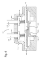
- FIG 4 shows schematically a sectional view of a third embodiment of hermetic pressure sensor 400 according to the present application.
- This embodiment differs from the previous embodiment in that the first housing part is out of one piece of metal and comprises both the bottom of the housing and the membrane section 416C.
- An advantage of this embodiment is that it is less complex.
- a disadvantage is that the membrane could easily be reached through the large port by objects and thus be damaged.
- the membrane section 416C is surrounded by an annular rigid section 416B1.
- An annular bending section 416 connects the annular rigid section to an annular outer section 414A of the first housing part.
- the annular bending section 416B2 has a thickness which is smaller than the thickness of the rigid part 416B1.
- the bending section 416B2 is angled with respect to the membrane section 416C.
- the springy electrical connection elements are open-coil springs 450 with a central axis perpendicular to the PCB 430.
- Figure 5 shows schematically a sectional view of a fourth embodiment of a pressure sensor with an hermetic housing with reduced sensitivity for forces acting on the hermetic housing.
- This embodiment differs from the third embodiment in the wave-like section 516B which couples the membrane section 516C to the annular outer section 516A.
- the mechanical path between the annular outer section and membrane section is increased further.
- the full metal bottom part 516 comprises an annular wave-like section which comprises from the membrane section 516C of the bottom part 516 to the outer section 516A of the bottom part 516 subsequently a first rigid part 516B1, 516B2, a first bending part 516B3, a second rigid part 516B4 and a second bending part 516B5.
- the membrane section 516C has the thinnest thickness of the bottom part 516.
- the bending parts 516B3, 516B5 have a thickness smaller than the rigid parts 516B1, 516B2 and 516B4.
- the first rigid part comprises a vertical part 516B1 and a horizontal part 516B2.
- the membrane section has to be surrounded by a rigid part to reduce the influence of parasitic effects in the measured pressure signal. If the vertical part 516B1 has a comparable thickness as the membrane section 516C, a fluid pressure acting on the bottom part will bend both the membrane section and the vertical part. However the bending of the vertical part will influence the stress in the membrane section and thus influence the measured fluid pressure. By having a rigid part surrounding the membrane section, this kind of distortion in the measured fluid pressure in reduced significantly.
- Method of assembling a hermetic pressure sensor comprises the following actions. Firstly, a first housing structure is provided.
- the first housing structure could be a one part piece as disclosed in Figs. 4 and 5 or a two part piece comprising the membrane part and the bottom part as disclosed in Figs. 2 and 3 .
- the membrane part is hermetically coupled to the bottom part by an annular weld.
- the PCB is disposed/attached in/to the first housing structure.
- a support structure is already attached to the PCB by for example a reflow process. The support structure is after placing the PCB in the first housing structure attached to the first housing structure by means welding or gluing.
- the strain sensing elements on the membrane are electrically coupled to the PCB.
- an alignment structure 145 is positioned on the PCB and open-coil springs are positioned in the alignment structure.
- springy electrical connection elements are already attached to the PCB by a reflow process.
- the second housing structure is provided and positioned above the PCB to form a closed cavity in which the PCB and strain gages are located. Now a stack of components is created the first housing structure, the PCB, springy electrical connection elements and the second housing structure. Finally, the second housing structure forming a cover over the first housing structure is hermetically connected to the first housing structure by means of an annular weld.
- the presented embodiments are suitable for transmission application in the automotive industry which measure pressure in an operating range of 0 - 20 Bar and which withstands pressure spikes in the measured medium up to 120 Bar. For other applications the operating range could be 0 - 70 Bar. Especially for measuring relative low pressures it is important that there is a constant internal pressure in the housing.
- the proposed designs consist of fewer potential leak paths by reducing the amount of required welds and the weld length.
- glass-to-metal seals are only used in the openings of the second housing part around the connection pins. As this side is not subjected to the fluid pressure to be measured, the risk of damage to the glass-to metal seals due to fluid pressure variations is negligible.
- the design is cost effective as it consists of a minimum amount of parts and processes, thereby reaching irreducible complexity: smallest amount of components possible to still fulfil the function and be manufacturable.
- the senor Due to the wave-like section the sensor copes with non-uniform forces on the sensor housing without significant effect on the output signal. It should be noted that the concept could also be applied in other type of pressure sensors which are used in an harsh environment.
- the disclosed housings are disc-shaped, with a height around 1 cm.
- the housing could be in the form of a plug, wherein the first housing structure comprises an external thread to mount the sensor in an opening of a device.
- the described embodiment all comprises springy electrical connection elements to couple the connection pint to the PCB.
- the springy electrical connection elements could be replaced by a flex foil.
- this embodiment requires more processes to manufacture the sensor and consequently the manufacturing process more complex.
Landscapes
- Physics & Mathematics (AREA)
- General Physics & Mathematics (AREA)
- Measuring Fluid Pressure (AREA)
- Pressure Sensors (AREA)
Abstract
Description
- The invention relates to a hermetic pressure sensor and a method for assembling a hermetic pressure sensor. More particular the invention relates to a pressure sensor to be used in automatic transmission applications to measure the pressure of the transmission oil.
- The main task of a hermetic, i.e. gas-tight, pressure sensor is to measure pressure in harsh or dangerous environmental conditions. A first important reason to have a hermetic sensor is that the environment can damage the elements of the sensor which are enclosed in the housing of the sensor. Damage could make the sensor malfunctioning. A second important reason is to have a constant internal pressure which is important for low pressure sensing accuracy. In practice, a sensor housing is considered hermetic when during a Helium leak test, the leakage does not exceed the limit of approximately 5×10⁻⁸ mBar×I/sec He.
- A hermetic pressure sensor is known from
US6763724 . This pressure sensor has a tubular port fitting and a tubular housing, which makes the design relatively high. A flange of the housing and the port fitting are welded to a support flange forming a hermetic seal. A compressive force on an O-ring forms a liquid-tight seal and maintains an axial load on the entire stack of components in the housing. Consequently, the housing is not gas-tight and the electrical elements are not hermetical sealed in the housing. - For transmission application there is a need for smaller fully hermetic sensors. This means that the sensor should have less height. Furthermore electronics of the sensor needs to be sealed from the measured media, in particular to prevent possible copper-sulfur corrosion.
- Smaller pressure sensors are known from
US20090282926A1 andUS8516897B1 . The sensors comprise a hermetic housing for the sensor element. The use a sensor chip having a glass base which is disposed in a hermetically sealed housing. A diaphragm is formed in the sensor chip. The glass base is fused to the housing to form a glass to metal seal. A glass to metal seal is a potential mode of failure in at least two cases: 1) a lack of a hermetic connection (e.g. due to a fault in the soldering process), 2) glass is a brittle material that may crack when pressure peaks and dynamic forces are applied. As the fluid pressure is acting directly on sensor chip, the glass base and connections (glass-silicon connection and glass-metal connection), there is a potential risk that the pressure sensor will malfunction due to damage of the glass base or any of the glass-connections. - It is an object of the present invention to provide an improved hermetic pressure sensor with a gas-tight housing structure which is at least one of: reliable, cheaper to manufacture, producible in high volume by means of semi-or full automatic production processes, long lasting and/or robust to harsh pressure media, less sensitive to point forces acting on the sensor housing, withstanding the temperature and vibration typical of an automotive transmission application. The sensor can also be exploited for other automotive applications like liquid fuel pressure sensing and sensing oil pressure.
- According to a first aspect of the invention, this object is achieved by a measuring plug having the features of claim 1. Advantageous embodiments and further ways of carrying out the invention may be attained by the measures mentioned in the dependent claims.
- A hermetic pressure sensor according to the invention is characterized in that the sensor comprises a hermetic housing with a membrane section to be exposed to a fluid pressure. At least one strain sensing element is arranged in the housing and attached to the membrane section. The housing comprises a first housing structure and a second housing structure. The first housing structure comprises the membrane section. The second housing structure comprises a housing part with at least two openings. Electrical connection pins pass through the at least two openings. The electrical connection pins are affixed in the at least two openings by a non-conductive and hermetic sealing material. The first housing structure and the second housing structure are hermetically connected to each other. The first housing structure comprises a fluid facing outer surface to be exposed to the fluid pressure wherein the fluid facing outer surface is a full metal outer surface.
- These features provide a housing around the electronics in the housing which is hermetic. Hermetic in the context of the present application means gas-tight and not only liquid-tight. Furthermore, the part of the housing that is contact with the varying fluid pressure comprises material having substantially similar characteristics with respect to pressure and temperature and no brittle material is used that may crack when pressure peaks and dynamic forces are applied. As a consequence, the potential risk that the pressure sensor will malfunction due to damage of the housing is reduced significantly.
- In an embodiment, the first housing structure comprises a bottom part and a membrane part. The bottom part comprises a pressure supply opening. The membrane part comprises the membrane section and is hermetically connected to the base part. The membrane section is in pressure contact with the fluid via a cavity between the bottom part and the membrane part and the pressure supply opening. This feature provides a structure wherein the bottom part protects the membrane for damage by external objects.
- In a further embodiment, the bottom part and the membrane part are hermetically connected by an annular weld. A solid state welding process or any other suitable welding process could be used to locally join the two parts. As a result the new part does not comprise discontinuities in material characteristics. In this way, the risk of damage due to temperature and pressure shocks is reduced. In another embodiment with similar advantages, the first housing structure and the second housing structure are hermetically connected by an annular weld.
- In an embodiment, the first housing structure comprises around the membrane section an annular wave-like section. By these features, the length of the material path between the exterior of the housing and the membrane section is extended. This reduces the sensitivity of the sensor for point forces acting on the exterior of the housing. In an embodiment, a cross section of the annular wave-like section comprises at least one U-turn-like shape.
- In an alternative embodiment, the first housing structure further comprises an annular base part, an annular rigid part and an annular bending part, the membrane section is joined via subsequently the rigid part and the bending part to the base part, the rigid part having a thickness larger than the bending part. The bending part absorbs resultants of point forces acting on the exterior and the rigid part forms a barrier for the remaining forces due to the point forces. As a result of the sensitivity of the sensor for point forces or asymmetric forces acting on the housing is reduced significantly.
- In a further embodiment, the bending part is at an angle with respect to the membrane section. This feature improves the bending characteristics for forces acting on the exterior of the housing which are parallel to the membrane and consequently the force absorption of the bending part.
- In an embodiment, the sensor further comprises a PCB arranged in the housing, the at least one strain sensing element is electrically coupled to the PCB by bonding wires. This feature enables to mechanically uncouple to PCB and the membrane and to provide a reliable electrical connection between electronics on the PCB and the strain sensing element.
- In a further embodiment, springy electrical connection elements couple electrically the electrical connection pins to the PCB. As a result of these features, a reliable electrical connection is established between the electrical connection pins and the PCB when closing the housing with the second housing structure. The electrical connection can withstand the vibration requirements. Some embodiments of springy electrical connection elements are an open-coil helical spring, S-shaped leaf spring and a U-shaped flat spring.
- In an embodiment, the hermetic housing is disk-shaped. This feature enables to use the pressure sensor in applications where limited height is available for positioning the pressure sensor.
- In an embodiment, the strain sensing element is a micro fused silicon strain gage.
- In a second aspect there is provided a method of assembling a hermetic pressure sensor. The method comprises:
- providing a first housing structure comprising a membrane section to be exposed to a fluid pressure, at least one strain sensing element is attached to the membrane section, the first housing structure comprises a fluid facing outer surface to be exposed to the fluid pressure which fluid facing outer surface is a full metal outer surface;
- disposing a PCB in the first housing structure;
- electrically connecting the at least one strain sensing element to the PCB by bonding wires;
- providing a second housing structure comprising a housing part with at least two openings and electrical connection pins passing through the at least two openings by a non-conductive and hermetic sealing material;
- creating a stack of components comprising the first housing structure, the PCB, springy electrical connection elements and the second housing structure; and,
- hermetically connecting the second housing structure to the first housing structure.
- In a further embodiment the first housing structure comprises a bottom part and a membrane part, the bottom part comprises an annular sidewall and a base part with a pressure supply opening, the membrane part comprises the membrane section. The membrane section designed to be in pressure contact with the fluid via a cavity between the base part and the membrane part and the pressure supply opening. The method further comprises hermetically connecting the membrane part to the bottom part by an annular weld
- Other features and advantages will become apparent from the following detailed description, taken in conjunction with the accompanying drawings which illustrate, by way of example, various features of embodiments.
- These and other aspects, properties and advantages will be explained hereinafter based on the following description with reference to the drawings, wherein like reference numerals denote like or comparable parts, and in which:
-
Fig. 1 shows schematically an exploded view of a first embodiment of a pressure sensor; -
Fig. 2 shows schematically a cross sectional view of the first embodiment; -
Fig. 3 shows schematically a cross sectional view of a second embodiment of a pressure sensor; -
Fig. 4 shows schematically a cross sectional view of a third embodiment of a pressure sensor; and, -
Fig. 5 shows schematically a cross sectional view of a fourth embodiment. -
Figures 1 and2 shows respectively an exploded view and sectional view of a first embodiment of a hermetic pressure sensor according to the present application. Hermetic in the context of the present application means completely airtight. The sensor is particularly designed for transmission applications wherein the electronics of the sensor needs to be sealed from the measured media, to prevent possible copper-sulphur corrosion. The sensor is robust, simple to manufacture, airtight and low-cost. The main task of the hermetic pressure sensor is to measure pressure in harsh or dangerous environmental conditions. - The pressure sensor comprises a hermetic disk shaped housing with a
first housing structure 114 and asecond housing structure 112. Disk-shaped in the context of the present application is: having a height smaller than the width of the housing. A height in the range of 0,75 cm - 1,5 cm has been found possible. The first housing structure comprises a metalbottom part 114 and ametal membrane part 116. The metalbottom part 114 and themembrane part 116 are hermetically connected by anannular weld 220. Thebottom part 114 comprises apressure supply opening 114C, a sealingsurface part 114B and aside wall part 114A. Via thepressure supply opening 114C, the fluid can flow in acavity 260 between themembrane part 116 and thebottom part 114. In this way, the first housing structure comprises a fluid facing outer surface which is formed by a fluid facing surface of the membrane part and the surface part of the bottom part that is in contact with the fluid to be measured. - The
membrane part 116 comprises amembrane section 116C, an annular wave-like section 116B and anannular support section 116A. The annular wave-like section surrounds themembrane section 116C and thesupport section 116A surrounds the annular wave-like section 116B. The membrane section has a first thickness which is thinner than the thickness of the annular wave-like section and the support section. In the present embodiment, a cross section of the wave-like section includes a U-turn-like shape. - A
strain sensing elements 120 is attached to the membrane section. A strain sensing element comprises two strain gages. A strain sensing element is positioned such that one strain gage is put into compression and the other strain gage is put into tension when a fluid pressure is applied on the fluid facing surface. The strain gages of the strain sensing element form a half bridge of a Wheatstone bridge. It might also be possible to use two strain sensing elements. The four strain gages of the two strain sensing elements are electrically coupled to form a full Wheatstone bridge. The angle between the line from the centre of the membrane to one of the strain sensing elements and the line from the centre of the membrane to another of the strain sensing elements is in an advantageous embodiment 90 degrees. The strain sensing element is preferably a micro fused silicon strain gage. In that case the strain gage is attached to the membrane section by glass material with the glass material bonded to both the strain gage and the membrane surface in accordance with conventional strain gage techniques. The concept of the present application could also applied with use of any other type of strain gages, such a semiconductor strain gages (piezoresistors), foil strain gages, thin film strain gages, thick film strain gages, polysilicon strain gages and capacitive strain gages - The
second housing structure 112 comprises ametal housing part 112A with three openings and three electrical connection pins 112B. The three electrical connection pins 112 are affixed in the three openings by a non-conductive andhermetic sealing material 112C, for example glass. It should be noted that depending on the implementation, the pressure sensor comprises 2 or more electrical connection pins. - The
first housing structure 114 and thesecond housing structure 112 are hermetically connected to each other by means of anannular weld 230. The first housing structure and the second housing structure form a compartment wherein a stack of components are positioned. The stack comprises asupport ring 140, aPCB 130, springyelectrical connection elements 150 and analignment structure 145. ThePCB 130 is provided with electronic circuitry. The electronic circuitry is arranged to perform at least one of the following actions: temperature compensation of electrical signals generated by the twostrain sensing elements 120 forming the Wheatstone bridge, calibration, internal fault detection, converting the electrical signal(s) from the strain sensing elements to a conditioned measurement signal, i.e. a signal indicative of the fluid pressure. Bonding wires connect strain sensing elements to the electronic circuitry. The electronic circuitry could further be configured to perform the necessary calibration processes. The support ring is welded to a raised edge of themembrane part 116. The PCB is coupled to the support ring by mean is a reflow soldering process. Thealignment structure 145 comprises openings to receive the springy electrical connection elements. In the present embodiment the springy electrical connections elements are in the form of an open-coil helical spring. Thealignment structure 145 aligns first ends of the springyelectrical connection elements 150 on contact areas on the PCB and aligns opposite second ends on the electrical connection pins 112B. - A characteristic of the annular wave-
like section 116B is that the "wave" enlarges the mechanical path betweenmembrane 116C section the outer surfaces of the hermetical housing. As a result of this, the sensor is less sensitive for point forces and uniform concentric forces acting on the housing. In use, an O-ring, not shown, is compressed between the sealingsurface 114D of the housing and a surface of the device which fluid pressure has to be measured. The O-ring is centred around thepressure supply opening 114C. The sealingsurface 114D is a recess with a small depth in the lower side of the housing. Flanges 114E around the sealingsurface 114D protect the O-ring for to high compressing and damaging of the sealing surface in case the mounting force will become too high. The compression force of the O-ring will push thesealing surface part 114B upwards by a uniform concentric force around the supply opening. As a result of this the bottom part will deform and resultant forces will act on theannular support section 116A of themembrane part 116. The part of the wave-like section 116B with least thickness will deform and the stiff and rigid part of the wave-like section between the relative thin part of the wavelike section and themembrane section 116C will deform minimally. In this way, the influence of concentric and point forces acting on the housing on the surface of themembrane section 116C is reduced significantly. It should be noted that the deformation of the bottom side of the housing is larger as the size of the O-ring decreases. Furthermore, as "flexible" bonding wires are used to couple the strain sensing elements on the membrane section to the PCB, the membrane section is mechanically decoupled for force acting on PCB due to the springy electrical connection elements. -
Figure 3 shows a cross sectional view of a second embodiment of apressure sensor 300 according to the present application. The second embodiment differs mainly in the composition of the disk-shaped hermetic housing. The hermetic housing comprises abottom part 314B, amembrane part 316A, asidewall part 314A and acover part 312A. Themembrane part 316A is hermetically connected to thebottom part 314B by means of an annular weld. Thesidewall part 314A is hermetically coupled to thebottom part 314B by means of an annular weld. Thecover part 312A is hermetically coupled to thesidewall part 314A by means of an annular weld. Depending on the implementation of the manufacturing process, the assembly of the bottom part, membrane part and sidewall part form the first housing structure and the cover part the second housing structure or the assembly of bottom part and the membrane part form the first housing structure and the assembly of the sidewall part and the cover part form the second housing structure. Thesensor 300 comprises in the housing asupport structure 340 and aPCB part 330. Thesupport structure 340 is coupled to thePCB 330 by a reflow process. The combination of support structure and PCB is attached to an edge of a vertical surface of the first housing part by a glue, weld or epoxy. - The
cover part 312A comprises at least two openings and at least two electrical connection pins 312B. The at least two electrical connection pins 312B pass through the openings in thecover part 312A and are affixed in the openings by a non-conductivehermetic sealing material 312C. The springyelectrical connection elements 350 electrically connect circuitry on thePCB 330 to the electrical connection pins 312B. In this embodiment the springyelectrical connection elements 350 are in the form of U-shaped flat springs. The flat springs are reflowed to contact surfaces of thePCB 330. During assembly of the first and second housing structure, the flat springs are pressed against onto respective ends of the connectingpins 312B which project into the interior of the housing. Instead of U-shaped flat springs, other shapes might be used for example S-shaped flat springs. It might further be possible to use conductive rubber or conductive elastomeric composites as springy electrical connection elements. - In
figure 3 , the thickness of the respective sections of the membrane part are indicated. From the centre of the membrane part to the outside, the membrane part comprises the following sections:membrane section 316C, an annular rigid part 316B1, an annular bending part 316B2, 316B3 andannular affixing section 316A. Themembrane section 316A has a thickness a. The annular rigid part is angled with respect to the plane of the membrane section and has a thickness b, wherein thickness b > thickness a. The annular bending part has two annular sections. The first section 316B2 is substantially parallel to themembrane section 316A and has a thickness c. The second section 316B3 is angled with respect to the first section 316B2 and has a thickness d. Thickness c and d are both thinner than the thickness b and thicker than thickness a. If a mounting force is acting on or via thebottom part 314, the force has to pass first the annular bending part and subsequently the annular rigid part before a resultant of the force will be acting on the membrane section. As the bending part is thinner than the rigid part, the main part of the mounting force will result in bending of the bending part and only a small remaining part will act on the rigid part. Consequently, an even smaller part of the force acting on the remaining part will pass the rigid part and influence stress in the membrane section. In this way, the sensitivity for both point (asymmetrical) and uniform (concentric) forces acting on the exterior of the hermetic housing is reduced significantly by the wave-like section, which comprises the annular rigid part and the annular bending part. -
Figure 4 shows schematically a sectional view of a third embodiment ofhermetic pressure sensor 400 according to the present application. This embodiment differs from the previous embodiment in that the first housing part is out of one piece of metal and comprises both the bottom of the housing and themembrane section 416C. An advantage of this embodiment is that it is less complex. A disadvantage is that the membrane could easily be reached through the large port by objects and thus be damaged. To reduce the influence of forces acting on the housing, themembrane section 416C is surrounded by an annular rigid section 416B1. An annular bending section 416 connects the annular rigid section to an annularouter section 414A of the first housing part. The annular bending section 416B2 has a thickness which is smaller than the thickness of the rigid part 416B1. Furthermore, the bending section 416B2 is angled with respect to themembrane section 416C. The way to reduce the influence is similar to that in the previous embodiments. In this embodiments, the springy electrical connection elements are open-coil springs 450 with a central axis perpendicular to thePCB 430. -
Figure 5 shows schematically a sectional view of a fourth embodiment of a pressure sensor with an hermetic housing with reduced sensitivity for forces acting on the hermetic housing. This embodiment differs from the third embodiment in the wave-like section 516B which couples themembrane section 516C to the annularouter section 516A. In this embodiment, the mechanical path between the annular outer section and membrane section is increased further. The full metalbottom part 516 comprises an annular wave-like section which comprises from themembrane section 516C of thebottom part 516 to theouter section 516A of thebottom part 516 subsequently a first rigid part 516B1, 516B2, a first bending part 516B3, a second rigid part 516B4 and a second bending part 516B5. Themembrane section 516C has the thinnest thickness of thebottom part 516. The bending parts 516B3, 516B5 have a thickness smaller than the rigid parts 516B1, 516B2 and 516B4. The first rigid part comprises a vertical part 516B1 and a horizontal part 516B2. In general, the membrane section has to be surrounded by a rigid part to reduce the influence of parasitic effects in the measured pressure signal. If the vertical part 516B1 has a comparable thickness as themembrane section 516C, a fluid pressure acting on the bottom part will bend both the membrane section and the vertical part. However the bending of the vertical part will influence the stress in the membrane section and thus influence the measured fluid pressure. By having a rigid part surrounding the membrane section, this kind of distortion in the measured fluid pressure in reduced significantly. - Method of assembling a hermetic pressure sensor comprises the following actions. Firstly, a first housing structure is provided. The first housing structure could be a one part piece as disclosed in
Figs. 4 and5 or a two part piece comprising the membrane part and the bottom part as disclosed inFigs. 2 and3 . In the latter case, the membrane part is hermetically coupled to the bottom part by an annular weld. Then, the PCB is disposed/attached in/to the first housing structure. For the embodiment shown inFigs. 2 and3 , a support structure is already attached to the PCB by for example a reflow process. The support structure is after placing the PCB in the first housing structure attached to the first housing structure by means welding or gluing. By means of a bonding process, the strain sensing elements on the membrane are electrically coupled to the PCB. In case of the embodiment disclosed inFig. 2 , analignment structure 145 is positioned on the PCB and open-coil springs are positioned in the alignment structure. In the other embodiments, springy electrical connection elements are already attached to the PCB by a reflow process. Then, the second housing structure is provided and positioned above the PCB to form a closed cavity in which the PCB and strain gages are located. Now a stack of components is created the first housing structure, the PCB, springy electrical connection elements and the second housing structure. Finally, the second housing structure forming a cover over the first housing structure is hermetically connected to the first housing structure by means of an annular weld. - The presented embodiments are suitable for transmission application in the automotive industry which measure pressure in an operating range of 0 - 20 Bar and which withstands pressure spikes in the measured medium up to 120 Bar. For other applications the operating range could be 0 - 70 Bar. Especially for measuring relative low pressures it is important that there is a constant internal pressure in the housing. The proposed designs consist of fewer potential leak paths by reducing the amount of required welds and the weld length. Furthermore, glass-to-metal seals are only used in the openings of the second housing part around the connection pins. As this side is not subjected to the fluid pressure to be measured, the risk of damage to the glass-to metal seals due to fluid pressure variations is negligible. The design is cost effective as it consists of a minimum amount of parts and processes, thereby reaching irreducible complexity: smallest amount of components possible to still fulfil the function and be manufacturable.
- Due to the wave-like section the sensor copes with non-uniform forces on the sensor housing without significant effect on the output signal. It should be noted that the concept could also be applied in other type of pressure sensors which are used in an harsh environment. The disclosed housings are disc-shaped, with a height around 1 cm. For other applications, the housing could be in the form of a plug, wherein the first housing structure comprises an external thread to mount the sensor in an opening of a device.
- It should be noted that the described embodiment all comprises springy electrical connection elements to couple the connection pint to the PCB. The springy electrical connection elements could be replaced by a flex foil. However, this embodiment requires more processes to manufacture the sensor and consequently the manufacturing process more complex.
- While the invention has been described in terms of several embodiments, it is contemplated that alternatives, modifications, permutations and equivalents thereof will become apparent to those skilled in the art upon reading the specification and upon study of the drawings. The invention is not limited to the illustrated embodiments. Changes can be made without departing from the scope of the appended claims.
Claims (15)
- A hermetic pressure sensor (100) for measuring a fluid pressure, the pressure sensor comprises:- a hermetic housing comprising a membrane section (116C), the membrane section to be exposed to the fluid pressure;- at least one strain sensing element (120) arranged in the housing and attached to the membrane section;characterized in that,
the housing comprises a first housing structure (114,116) and a second housing structure (112), the first housing structure comprises the membrane section, the second housing structure comprises a housing part (112A) with at least two openings and electrical connection pins (112B) passing through the at least two openings, the electrical connection pins are affixed in the at least two openings by a non-conductive and hermetic sealing material (112C), the first housing structure and the second housing structure are hermetically connected to each other, the first housing structure comprises a fluid facing outer surface to be exposed to the fluid pressure wherein the fluid facing outer surface is a full metal outer surface. - The pressure sensor according to claim 1, wherein the first housing structure comprises a bottom part (114) and a membrane part (116), the bottom part comprises a pressure supply opening (114C), the membrane part (116) comprising the membrane section (116C) is hermetically connected to the bottom part (114), the membrane section (116C) is in pressure contact with the fluid via a cavity (260) between the base part and the membrane part and the pressure supply opening (114C).
- The pressure sensor according to claim 2, wherein the bottom part (114) and the membrane part (116) being hermetically connected by an annular weld.
- The pressure sensor according to any of the claim 1 - 3, wherein the first housing structure and the second housing structure are hermetically connected by an annular weld.
- The pressure sensor according to any of the claims 1 - 4, wherein the first housing structure comprises around the membrane section (116C) an annular wave-like section (116B).
- The pressure sensor according to claim 5, wherein a cross section of the annular wave-like section comprises at least one U-turn-like shape.
- The pressure sensor according to any of the claims 1 - 6, wherein the first housing structure further comprises an annular base part, an annular rigid part and an annular bending part, the membrane section is joined via the rigid part and the bending part to the base part, the rigid part having a thickness larger than the bending part.
- The pressure sensor according to claim 7, wherein the bending part is at an angle with respect to the membrane section.
- The pressure sensor according to any of the claims 1 - 8, wherein the sensor further comprises a PCB (130) arranged in the housing, the at least one strain sensing element is electrically coupled to the PCB by bonding wires.
- The pressure sensor according to claim 9, wherein springy electrical connection elements (150) couple electrically the electrical connection pins (112B) to the PCB (130).
- The pressure sensor according to claim 10, wherein a springy electrical connection element is one selected from a group comprising an open-coil helical spring, U-shaped flat spring, S-shaped flat spring, conductive rubber and other conductive elastomeric composites.
- The pressure sensor according to any of the claims 1 - 11, wherein the hermetic housing is disk-shaped.
- The pressure sensor according to any of the claims 1 - 12, wherein the strain sensing element is a micro fused silicon strain gage.
- Method of assembling a hermetic pressure sensor, the method comprising:- providing a first housing structure (114,116) comprising a membrane section (116C) to be exposed to a fluid pressure, at least one strain sensing element (120) is attached to the membrane section, the first housing structure comprises a fluid facing outer surface to be exposed to the fluid pressure which fluid facing outer surface is a full metal outer surface;- disposing a PCB (130) in the first housing structure;- electrically connecting the at least one strain sensing element (120) to the PCB by bonding wires;- providing a second housing structure (112) comprising a housing part (112A) with at least two openings and electrical connection pins (112B) passing through the at least two openings by a non-conductive and hermetic sealing material (112C);- creating a stack of components comprising the first housing structure, the PCB, springy electrical connection elements and the second housing structure; and,- hermetically connecting the second housing structure to the first housing structure.
- The method according to claim 14, wherein the first housing structure comprises a bottom part (114) and a membrane part (116), the bottom part comprises an annular sidewall (114A) and a base part (114B) with a pressure supply opening (114C), the membrane part (116) comprises the membrane section (116C); the membrane section (116C) to be in pressure contact with the fluid via a cavity (260) between the base part and the membrane part and the pressure supply opening (114C), the method further comprises hermetically connecting the membrane part (116) to the bottom part (114) by an annular weld.
Priority Applications (4)
| Application Number | Priority Date | Filing Date | Title |
|---|---|---|---|
| EP15180231.1A EP3128305B1 (en) | 2015-08-07 | 2015-08-07 | A hermetic pressure sensor |
| US15/222,305 US10473546B2 (en) | 2015-08-07 | 2016-07-28 | Hermetic pressure sensor having a bending part |
| JP2016151684A JP6812162B2 (en) | 2015-08-07 | 2016-08-02 | Sealed pressure sensor |
| KR1020160099698A KR102552452B1 (en) | 2015-08-07 | 2016-08-04 | A hermetic pressure sensor |
Applications Claiming Priority (1)
| Application Number | Priority Date | Filing Date | Title |
|---|---|---|---|
| EP15180231.1A EP3128305B1 (en) | 2015-08-07 | 2015-08-07 | A hermetic pressure sensor |
Publications (2)
| Publication Number | Publication Date |
|---|---|
| EP3128305A1 true EP3128305A1 (en) | 2017-02-08 |
| EP3128305B1 EP3128305B1 (en) | 2019-07-31 |
Family
ID=53783640
Family Applications (1)
| Application Number | Title | Priority Date | Filing Date |
|---|---|---|---|
| EP15180231.1A Active EP3128305B1 (en) | 2015-08-07 | 2015-08-07 | A hermetic pressure sensor |
Country Status (4)
| Country | Link |
|---|---|
| US (1) | US10473546B2 (en) |
| EP (1) | EP3128305B1 (en) |
| JP (1) | JP6812162B2 (en) |
| KR (1) | KR102552452B1 (en) |
Cited By (5)
| Publication number | Priority date | Publication date | Assignee | Title |
|---|---|---|---|---|
| DE102019209030B3 (en) * | 2019-06-21 | 2020-09-24 | Metallux Ag | Pressure sensor device |
| DE102019209033A1 (en) * | 2019-06-21 | 2020-12-24 | Metallux Ag | Pressure sensor device |
| US11428593B2 (en) * | 2019-11-20 | 2022-08-30 | Honeywell International Inc. | Methods and apparatuses for providing freeze resistant sensing assembly |
| EP4067852A1 (en) * | 2021-03-31 | 2022-10-05 | Robert Leeb | Device for measuring pressure |
| DE102021214945A1 (en) | 2021-12-22 | 2023-06-22 | Metallux Ag | Sensor unit for a sensor device for measuring pressure and/or force |
Families Citing this family (12)
| Publication number | Priority date | Publication date | Assignee | Title |
|---|---|---|---|---|
| US10295427B2 (en) * | 2017-04-04 | 2019-05-21 | Sensata Technologies, Inc. | Multi-chamber pressure sensing apparatus |
| JP6541083B1 (en) * | 2017-12-26 | 2019-07-10 | Smk株式会社 | Sensor connector |
| WO2019228635A1 (en) * | 2018-05-31 | 2019-12-05 | Autronica Fire & Security As | Printed circuit board for smoke detector |
| KR102085007B1 (en) * | 2018-10-10 | 2020-03-05 | 만도헬라일렉트로닉스(주) | Pressure Sensor Assembly |
| CN209326840U (en) | 2018-12-27 | 2019-08-30 | 热敏碟公司 | Pressure sensor and pressure transmitter |
| US11460363B2 (en) * | 2019-03-29 | 2022-10-04 | Honeywell International Inc. | Pressure sensors and methods of manufacturing a pressure sensor |
| US20210088402A1 (en) * | 2019-09-23 | 2021-03-25 | Arradiance, Llc | Vacuum Gauge Protector for Deposition Systems |
| CN113008448B (en) * | 2019-12-20 | 2022-06-21 | 黄羽婵 | Pressure sensing device of gas appliance |
| CN113108830A (en) * | 2020-12-31 | 2021-07-13 | 杭州三花研究院有限公司 | Sensor with a sensor element |
| KR102439306B1 (en) * | 2021-08-25 | 2022-09-02 | 김정기 | Compact pressure sensor having high responsiveness and assemblability |
| EP4396551A1 (en) | 2021-08-31 | 2024-07-10 | Huba Control Ag | Metal pressure measuring cell |
| CN113945320A (en) * | 2021-09-29 | 2022-01-18 | 吴伟玲 | Pressure sensor module |
Citations (5)
| Publication number | Priority date | Publication date | Assignee | Title |
|---|---|---|---|---|
| US6763724B2 (en) | 2002-07-10 | 2004-07-20 | Texas Instruments Incorporated | Hermetic pressure transducer |
| WO2008115346A2 (en) * | 2007-03-15 | 2008-09-25 | Rosemount Inc. | Welded header for pressure transmitter |
| US20090282926A1 (en) | 2008-04-30 | 2009-11-19 | Wolfgang Hauer | Pressure-sensor system |
| US8516897B1 (en) | 2012-02-21 | 2013-08-27 | Honeywell International Inc. | Pressure sensor |
| US20140033824A1 (en) * | 2012-06-25 | 2014-02-06 | Robert Bosch Gmbh | Pressure detection module and pressure sensor device having such a pressure detection module |
Family Cites Families (11)
| Publication number | Priority date | Publication date | Assignee | Title |
|---|---|---|---|---|
| US4939497A (en) * | 1989-04-18 | 1990-07-03 | Nippon Soken, Inc. | Pressure sensor |
| US5184515A (en) | 1989-06-22 | 1993-02-09 | Ic Sensors, Inc. | Single diaphragm transducer with multiple sensing elements |
| US6568276B1 (en) | 2000-08-04 | 2003-05-27 | Measurement Specialties, Inc. | Strain gauge based sensor with improved linearity |
| US6351998B1 (en) | 2000-09-19 | 2002-03-05 | General Motors Corporation | Method for designing a load cell |
| JP4843877B2 (en) | 2001-01-31 | 2011-12-21 | 株式会社デンソー | Semiconductor dynamic quantity sensor |
| US6742395B1 (en) * | 2002-12-20 | 2004-06-01 | Texas Instruments Incorporated | Hermetic pressure transducer |
| DE10332284A1 (en) * | 2003-07-16 | 2005-02-03 | Robert Bosch Gmbh | Pressure sensor has body with sealing forces decoupled from sensor membrane by groove midway between sensor element ends |
| JP4014006B2 (en) * | 2004-06-17 | 2007-11-28 | 株式会社山武 | Pressure sensor |
| DE102008033337A1 (en) | 2008-07-16 | 2010-01-21 | Endress + Hauser Gmbh + Co. Kg | Diaphragm seal and pressure gauge with such a diaphragm seal |
| US9148726B2 (en) * | 2011-09-12 | 2015-09-29 | Infineon Technologies Ag | Micro electrical mechanical system with bending deflection of backplate structure |
| DE102011088044A1 (en) * | 2011-12-08 | 2013-06-13 | Robert Bosch Gmbh | Pressure sensor arrangement for detecting a pressure of a fluid medium in a measuring space |
-
2015
- 2015-08-07 EP EP15180231.1A patent/EP3128305B1/en active Active
-
2016
- 2016-07-28 US US15/222,305 patent/US10473546B2/en active Active
- 2016-08-02 JP JP2016151684A patent/JP6812162B2/en active Active
- 2016-08-04 KR KR1020160099698A patent/KR102552452B1/en active IP Right Grant
Patent Citations (5)
| Publication number | Priority date | Publication date | Assignee | Title |
|---|---|---|---|---|
| US6763724B2 (en) | 2002-07-10 | 2004-07-20 | Texas Instruments Incorporated | Hermetic pressure transducer |
| WO2008115346A2 (en) * | 2007-03-15 | 2008-09-25 | Rosemount Inc. | Welded header for pressure transmitter |
| US20090282926A1 (en) | 2008-04-30 | 2009-11-19 | Wolfgang Hauer | Pressure-sensor system |
| US8516897B1 (en) | 2012-02-21 | 2013-08-27 | Honeywell International Inc. | Pressure sensor |
| US20140033824A1 (en) * | 2012-06-25 | 2014-02-06 | Robert Bosch Gmbh | Pressure detection module and pressure sensor device having such a pressure detection module |
Cited By (5)
| Publication number | Priority date | Publication date | Assignee | Title |
|---|---|---|---|---|
| DE102019209030B3 (en) * | 2019-06-21 | 2020-09-24 | Metallux Ag | Pressure sensor device |
| DE102019209033A1 (en) * | 2019-06-21 | 2020-12-24 | Metallux Ag | Pressure sensor device |
| US11428593B2 (en) * | 2019-11-20 | 2022-08-30 | Honeywell International Inc. | Methods and apparatuses for providing freeze resistant sensing assembly |
| EP4067852A1 (en) * | 2021-03-31 | 2022-10-05 | Robert Leeb | Device for measuring pressure |
| DE102021214945A1 (en) | 2021-12-22 | 2023-06-22 | Metallux Ag | Sensor unit for a sensor device for measuring pressure and/or force |
Also Published As
| Publication number | Publication date |
|---|---|
| US20170038272A1 (en) | 2017-02-09 |
| KR20170017801A (en) | 2017-02-15 |
| KR102552452B1 (en) | 2023-07-05 |
| US10473546B2 (en) | 2019-11-12 |
| EP3128305B1 (en) | 2019-07-31 |
| JP6812162B2 (en) | 2021-01-13 |
| JP2017053840A (en) | 2017-03-16 |
Similar Documents
| Publication | Publication Date | Title |
|---|---|---|
| EP3128305B1 (en) | A hermetic pressure sensor | |
| US7412894B2 (en) | Pressure sensing device incorporating pressure sensing chip in resin case | |
| JP4839648B2 (en) | Pressure sensor device | |
| JP5998379B2 (en) | Sensor device package and method | |
| US6550337B1 (en) | Isolation technique for pressure sensing structure | |
| JP6614747B2 (en) | Pressure sensing module and pressure sensor device comprising such a pressure sensing module | |
| US8499642B2 (en) | Hermetically sealed pressure sensing device | |
| US10190929B2 (en) | Pressure sensor device and pressure sensor device manufacturing method | |
| US20020029639A1 (en) | Isolation technique for pressure sensing structure | |
| EP3538857B1 (en) | Differential pressure sensor and fabrication | |
| EP2793010B1 (en) | Pressure sensor | |
| US8770032B2 (en) | Relative pressure sensor | |
| JPH0375537A (en) | Pressure sensitive element | |
| EP3205998B1 (en) | Open diaphragm harsh environment pressure sensor | |
| JP2020528150A (en) | Pressure sensor assemblies, measuring instruments, and how they are manufactured | |
| CN112262303B (en) | Pressure measuring device and method for producing the same | |
| CN106525328B (en) | Closed pressure sensor | |
| JP5278448B2 (en) | Pressure sensor device | |
| JP7087375B2 (en) | pressure sensor | |
| JP2016001162A (en) | Pressure sensor |
Legal Events
| Date | Code | Title | Description |
|---|---|---|---|
| PUAI | Public reference made under article 153(3) epc to a published international application that has entered the european phase |
Free format text: ORIGINAL CODE: 0009012 |
|
| STAA | Information on the status of an ep patent application or granted ep patent |
Free format text: STATUS: THE APPLICATION HAS BEEN PUBLISHED |
|
| AK | Designated contracting states |
Kind code of ref document: A1 Designated state(s): AL AT BE BG CH CY CZ DE DK EE ES FI FR GB GR HR HU IE IS IT LI LT LU LV MC MK MT NL NO PL PT RO RS SE SI SK SM TR |
|
| AX | Request for extension of the european patent |
Extension state: BA ME |
|
| STAA | Information on the status of an ep patent application or granted ep patent |
Free format text: STATUS: REQUEST FOR EXAMINATION WAS MADE |
|
| 17P | Request for examination filed |
Effective date: 20170808 |
|
| RBV | Designated contracting states (corrected) |
Designated state(s): AL AT BE BG CH CY CZ DE DK EE ES FI FR GB GR HR HU IE IS IT LI LT LU LV MC MK MT NL NO PL PT RO RS SE SI SK SM TR |
|
| STAA | Information on the status of an ep patent application or granted ep patent |
Free format text: STATUS: EXAMINATION IS IN PROGRESS |
|
| 17Q | First examination report despatched |
Effective date: 20180205 |
|
| GRAP | Despatch of communication of intention to grant a patent |
Free format text: ORIGINAL CODE: EPIDOSNIGR1 |
|
| STAA | Information on the status of an ep patent application or granted ep patent |
Free format text: STATUS: GRANT OF PATENT IS INTENDED |
|
| INTG | Intention to grant announced |
Effective date: 20190403 |
|
| GRAS | Grant fee paid |
Free format text: ORIGINAL CODE: EPIDOSNIGR3 |
|
| GRAA | (expected) grant |
Free format text: ORIGINAL CODE: 0009210 |
|
| STAA | Information on the status of an ep patent application or granted ep patent |
Free format text: STATUS: THE PATENT HAS BEEN GRANTED |
|
| AK | Designated contracting states |
Kind code of ref document: B1 Designated state(s): AL AT BE BG CH CY CZ DE DK EE ES FI FR GB GR HR HU IE IS IT LI LT LU LV MC MK MT NL NO PL PT RO RS SE SI SK SM TR |
|
| REG | Reference to a national code |
Ref country code: CH Ref legal event code: EP Ref country code: GB Ref legal event code: FG4D |
|
| REG | Reference to a national code |
Ref country code: AT Ref legal event code: REF Ref document number: 1161417 Country of ref document: AT Kind code of ref document: T Effective date: 20190815 |
|
| REG | Reference to a national code |
Ref country code: IE Ref legal event code: FG4D |
|
| REG | Reference to a national code |
Ref country code: DE Ref legal event code: R096 Ref document number: 602015034669 Country of ref document: DE |
|
| REG | Reference to a national code |
Ref country code: NL Ref legal event code: MP Effective date: 20190731 |
|
| REG | Reference to a national code |
Ref country code: LT Ref legal event code: MG4D |
|
| REG | Reference to a national code |
Ref country code: AT Ref legal event code: MK05 Ref document number: 1161417 Country of ref document: AT Kind code of ref document: T Effective date: 20190731 |
|
| PG25 | Lapsed in a contracting state [announced via postgrant information from national office to epo] |
Ref country code: PT Free format text: LAPSE BECAUSE OF FAILURE TO SUBMIT A TRANSLATION OF THE DESCRIPTION OR TO PAY THE FEE WITHIN THE PRESCRIBED TIME-LIMIT Effective date: 20191202 Ref country code: FI Free format text: LAPSE BECAUSE OF FAILURE TO SUBMIT A TRANSLATION OF THE DESCRIPTION OR TO PAY THE FEE WITHIN THE PRESCRIBED TIME-LIMIT Effective date: 20190731 Ref country code: NO Free format text: LAPSE BECAUSE OF FAILURE TO SUBMIT A TRANSLATION OF THE DESCRIPTION OR TO PAY THE FEE WITHIN THE PRESCRIBED TIME-LIMIT Effective date: 20191031 Ref country code: NL Free format text: LAPSE BECAUSE OF FAILURE TO SUBMIT A TRANSLATION OF THE DESCRIPTION OR TO PAY THE FEE WITHIN THE PRESCRIBED TIME-LIMIT Effective date: 20190731 Ref country code: AT Free format text: LAPSE BECAUSE OF FAILURE TO SUBMIT A TRANSLATION OF THE DESCRIPTION OR TO PAY THE FEE WITHIN THE PRESCRIBED TIME-LIMIT Effective date: 20190731 Ref country code: HR Free format text: LAPSE BECAUSE OF FAILURE TO SUBMIT A TRANSLATION OF THE DESCRIPTION OR TO PAY THE FEE WITHIN THE PRESCRIBED TIME-LIMIT Effective date: 20190731 Ref country code: LT Free format text: LAPSE BECAUSE OF FAILURE TO SUBMIT A TRANSLATION OF THE DESCRIPTION OR TO PAY THE FEE WITHIN THE PRESCRIBED TIME-LIMIT Effective date: 20190731 Ref country code: SE Free format text: LAPSE BECAUSE OF FAILURE TO SUBMIT A TRANSLATION OF THE DESCRIPTION OR TO PAY THE FEE WITHIN THE PRESCRIBED TIME-LIMIT Effective date: 20190731 Ref country code: BG Free format text: LAPSE BECAUSE OF FAILURE TO SUBMIT A TRANSLATION OF THE DESCRIPTION OR TO PAY THE FEE WITHIN THE PRESCRIBED TIME-LIMIT Effective date: 20191031 |
|
| PG25 | Lapsed in a contracting state [announced via postgrant information from national office to epo] |
Ref country code: AL Free format text: LAPSE BECAUSE OF FAILURE TO SUBMIT A TRANSLATION OF THE DESCRIPTION OR TO PAY THE FEE WITHIN THE PRESCRIBED TIME-LIMIT Effective date: 20190731 Ref country code: IS Free format text: LAPSE BECAUSE OF FAILURE TO SUBMIT A TRANSLATION OF THE DESCRIPTION OR TO PAY THE FEE WITHIN THE PRESCRIBED TIME-LIMIT Effective date: 20191130 Ref country code: LV Free format text: LAPSE BECAUSE OF FAILURE TO SUBMIT A TRANSLATION OF THE DESCRIPTION OR TO PAY THE FEE WITHIN THE PRESCRIBED TIME-LIMIT Effective date: 20190731 Ref country code: RS Free format text: LAPSE BECAUSE OF FAILURE TO SUBMIT A TRANSLATION OF THE DESCRIPTION OR TO PAY THE FEE WITHIN THE PRESCRIBED TIME-LIMIT Effective date: 20190731 Ref country code: GR Free format text: LAPSE BECAUSE OF FAILURE TO SUBMIT A TRANSLATION OF THE DESCRIPTION OR TO PAY THE FEE WITHIN THE PRESCRIBED TIME-LIMIT Effective date: 20191101 Ref country code: ES Free format text: LAPSE BECAUSE OF FAILURE TO SUBMIT A TRANSLATION OF THE DESCRIPTION OR TO PAY THE FEE WITHIN THE PRESCRIBED TIME-LIMIT Effective date: 20190731 |
|
| PG25 | Lapsed in a contracting state [announced via postgrant information from national office to epo] |
Ref country code: TR Free format text: LAPSE BECAUSE OF FAILURE TO SUBMIT A TRANSLATION OF THE DESCRIPTION OR TO PAY THE FEE WITHIN THE PRESCRIBED TIME-LIMIT Effective date: 20190731 |
|
| PG25 | Lapsed in a contracting state [announced via postgrant information from national office to epo] |
Ref country code: RO Free format text: LAPSE BECAUSE OF FAILURE TO SUBMIT A TRANSLATION OF THE DESCRIPTION OR TO PAY THE FEE WITHIN THE PRESCRIBED TIME-LIMIT Effective date: 20190731 Ref country code: IT Free format text: LAPSE BECAUSE OF FAILURE TO SUBMIT A TRANSLATION OF THE DESCRIPTION OR TO PAY THE FEE WITHIN THE PRESCRIBED TIME-LIMIT Effective date: 20190731 Ref country code: PL Free format text: LAPSE BECAUSE OF FAILURE TO SUBMIT A TRANSLATION OF THE DESCRIPTION OR TO PAY THE FEE WITHIN THE PRESCRIBED TIME-LIMIT Effective date: 20190731 Ref country code: DK Free format text: LAPSE BECAUSE OF FAILURE TO SUBMIT A TRANSLATION OF THE DESCRIPTION OR TO PAY THE FEE WITHIN THE PRESCRIBED TIME-LIMIT Effective date: 20190731 Ref country code: EE Free format text: LAPSE BECAUSE OF FAILURE TO SUBMIT A TRANSLATION OF THE DESCRIPTION OR TO PAY THE FEE WITHIN THE PRESCRIBED TIME-LIMIT Effective date: 20190731 |
|
| PG25 | Lapsed in a contracting state [announced via postgrant information from national office to epo] |
Ref country code: CZ Free format text: LAPSE BECAUSE OF FAILURE TO SUBMIT A TRANSLATION OF THE DESCRIPTION OR TO PAY THE FEE WITHIN THE PRESCRIBED TIME-LIMIT Effective date: 20190731 Ref country code: LI Free format text: LAPSE BECAUSE OF NON-PAYMENT OF DUE FEES Effective date: 20190831 Ref country code: CH Free format text: LAPSE BECAUSE OF NON-PAYMENT OF DUE FEES Effective date: 20190831 Ref country code: IS Free format text: LAPSE BECAUSE OF FAILURE TO SUBMIT A TRANSLATION OF THE DESCRIPTION OR TO PAY THE FEE WITHIN THE PRESCRIBED TIME-LIMIT Effective date: 20200224 Ref country code: SM Free format text: LAPSE BECAUSE OF FAILURE TO SUBMIT A TRANSLATION OF THE DESCRIPTION OR TO PAY THE FEE WITHIN THE PRESCRIBED TIME-LIMIT Effective date: 20190731 Ref country code: MC Free format text: LAPSE BECAUSE OF FAILURE TO SUBMIT A TRANSLATION OF THE DESCRIPTION OR TO PAY THE FEE WITHIN THE PRESCRIBED TIME-LIMIT Effective date: 20190731 Ref country code: LU Free format text: LAPSE BECAUSE OF NON-PAYMENT OF DUE FEES Effective date: 20190807 Ref country code: SK Free format text: LAPSE BECAUSE OF FAILURE TO SUBMIT A TRANSLATION OF THE DESCRIPTION OR TO PAY THE FEE WITHIN THE PRESCRIBED TIME-LIMIT Effective date: 20190731 |
|
| REG | Reference to a national code |
Ref country code: BE Ref legal event code: MM Effective date: 20190831 |
|
| REG | Reference to a national code |
Ref country code: DE Ref legal event code: R097 Ref document number: 602015034669 Country of ref document: DE |
|
| PLBE | No opposition filed within time limit |
Free format text: ORIGINAL CODE: 0009261 |
|
| STAA | Information on the status of an ep patent application or granted ep patent |
Free format text: STATUS: NO OPPOSITION FILED WITHIN TIME LIMIT |
|
| PG2D | Information on lapse in contracting state deleted |
Ref country code: IS |
|
| PG25 | Lapsed in a contracting state [announced via postgrant information from national office to epo] |
Ref country code: IE Free format text: LAPSE BECAUSE OF NON-PAYMENT OF DUE FEES Effective date: 20190807 Ref country code: IS Free format text: LAPSE BECAUSE OF FAILURE TO SUBMIT A TRANSLATION OF THE DESCRIPTION OR TO PAY THE FEE WITHIN THE PRESCRIBED TIME-LIMIT Effective date: 20191030 |
|
| 26N | No opposition filed |
Effective date: 20200603 |
|
| PG25 | Lapsed in a contracting state [announced via postgrant information from national office to epo] |
Ref country code: BE Free format text: LAPSE BECAUSE OF NON-PAYMENT OF DUE FEES Effective date: 20190831 Ref country code: SI Free format text: LAPSE BECAUSE OF FAILURE TO SUBMIT A TRANSLATION OF THE DESCRIPTION OR TO PAY THE FEE WITHIN THE PRESCRIBED TIME-LIMIT Effective date: 20190731 |
|
| PG25 | Lapsed in a contracting state [announced via postgrant information from national office to epo] |
Ref country code: FR Free format text: LAPSE BECAUSE OF NON-PAYMENT OF DUE FEES Effective date: 20190930 |
|
| PG25 | Lapsed in a contracting state [announced via postgrant information from national office to epo] |
Ref country code: CY Free format text: LAPSE BECAUSE OF FAILURE TO SUBMIT A TRANSLATION OF THE DESCRIPTION OR TO PAY THE FEE WITHIN THE PRESCRIBED TIME-LIMIT Effective date: 20190731 |
|
| PG25 | Lapsed in a contracting state [announced via postgrant information from national office to epo] |
Ref country code: HU Free format text: LAPSE BECAUSE OF FAILURE TO SUBMIT A TRANSLATION OF THE DESCRIPTION OR TO PAY THE FEE WITHIN THE PRESCRIBED TIME-LIMIT; INVALID AB INITIO Effective date: 20150807 Ref country code: MT Free format text: LAPSE BECAUSE OF FAILURE TO SUBMIT A TRANSLATION OF THE DESCRIPTION OR TO PAY THE FEE WITHIN THE PRESCRIBED TIME-LIMIT Effective date: 20190731 |
|
| PG25 | Lapsed in a contracting state [announced via postgrant information from national office to epo] |
Ref country code: MK Free format text: LAPSE BECAUSE OF FAILURE TO SUBMIT A TRANSLATION OF THE DESCRIPTION OR TO PAY THE FEE WITHIN THE PRESCRIBED TIME-LIMIT Effective date: 20190731 |
|
| P01 | Opt-out of the competence of the unified patent court (upc) registered |
Effective date: 20230708 |
|
| PGFP | Annual fee paid to national office [announced via postgrant information from national office to epo] |
Ref country code: GB Payment date: 20230828 Year of fee payment: 9 |
|
| PGFP | Annual fee paid to national office [announced via postgrant information from national office to epo] |
Ref country code: DE Payment date: 20230829 Year of fee payment: 9 |