EP3205998B1 - Open diaphragm harsh environment pressure sensor - Google Patents
Open diaphragm harsh environment pressure sensor Download PDFInfo
- Publication number
- EP3205998B1 EP3205998B1 EP17155350.6A EP17155350A EP3205998B1 EP 3205998 B1 EP3205998 B1 EP 3205998B1 EP 17155350 A EP17155350 A EP 17155350A EP 3205998 B1 EP3205998 B1 EP 3205998B1
- Authority
- EP
- European Patent Office
- Prior art keywords
- diaphragm
- wafer
- pressure
- housing
- isolator
- Prior art date
- Legal status (The legal status is an assumption and is not a legal conclusion. Google has not performed a legal analysis and makes no representation as to the accuracy of the status listed.)
- Active
Links
- 239000012530 fluid Substances 0.000 claims description 54
- 238000000034 method Methods 0.000 claims description 41
- 230000004044 response Effects 0.000 claims description 6
- 238000009530 blood pressure measurement Methods 0.000 claims description 4
- 238000012354 overpressurization Methods 0.000 claims description 3
- 238000003801 milling Methods 0.000 claims 1
- 238000007789 sealing Methods 0.000 claims 1
- 230000008569 process Effects 0.000 description 34
- 239000003921 oil Substances 0.000 description 15
- 238000010586 diagram Methods 0.000 description 14
- XUIMIQQOPSSXEZ-UHFFFAOYSA-N Silicon Chemical compound [Si] XUIMIQQOPSSXEZ-UHFFFAOYSA-N 0.000 description 11
- 239000010703 silicon Substances 0.000 description 11
- 229910052710 silicon Inorganic materials 0.000 description 11
- 230000035882 stress Effects 0.000 description 10
- NJPPVKZQTLUDBO-UHFFFAOYSA-N novaluron Chemical compound C1=C(Cl)C(OC(F)(F)C(OC(F)(F)F)F)=CC=C1NC(=O)NC(=O)C1=C(F)C=CC=C1F NJPPVKZQTLUDBO-UHFFFAOYSA-N 0.000 description 9
- 238000013461 design Methods 0.000 description 8
- 229910001030 Iron–nickel alloy Inorganic materials 0.000 description 7
- 230000006378 damage Effects 0.000 description 5
- 239000011521 glass Substances 0.000 description 5
- 239000012528 membrane Substances 0.000 description 5
- 238000000926 separation method Methods 0.000 description 5
- 238000004519 manufacturing process Methods 0.000 description 4
- 239000000463 material Substances 0.000 description 4
- 239000010935 stainless steel Substances 0.000 description 4
- 229910001220 stainless steel Inorganic materials 0.000 description 4
- 239000005388 borosilicate glass Substances 0.000 description 3
- 230000009172 bursting Effects 0.000 description 3
- 239000004593 Epoxy Substances 0.000 description 2
- 238000005452 bending Methods 0.000 description 2
- 239000000919 ceramic Substances 0.000 description 2
- 239000011248 coating agent Substances 0.000 description 2
- 238000000576 coating method Methods 0.000 description 2
- 230000003111 delayed effect Effects 0.000 description 2
- 239000011888 foil Substances 0.000 description 2
- 238000012546 transfer Methods 0.000 description 2
- 229910000838 Al alloy Inorganic materials 0.000 description 1
- 229910001020 Au alloy Inorganic materials 0.000 description 1
- 229910045601 alloy Inorganic materials 0.000 description 1
- 239000000956 alloy Substances 0.000 description 1
- XAGFODPZIPBFFR-UHFFFAOYSA-N aluminium Chemical compound [Al] XAGFODPZIPBFFR-UHFFFAOYSA-N 0.000 description 1
- 238000013459 approach Methods 0.000 description 1
- 230000000712 assembly Effects 0.000 description 1
- 238000000429 assembly Methods 0.000 description 1
- 230000008030 elimination Effects 0.000 description 1
- 238000003379 elimination reaction Methods 0.000 description 1
- PCHJSUWPFVWCPO-UHFFFAOYSA-N gold Chemical compound [Au] PCHJSUWPFVWCPO-UHFFFAOYSA-N 0.000 description 1
- 239000010931 gold Substances 0.000 description 1
- 229910052737 gold Inorganic materials 0.000 description 1
- 239000003353 gold alloy Substances 0.000 description 1
- 238000002955 isolation Methods 0.000 description 1
- 239000007788 liquid Substances 0.000 description 1
- 238000005259 measurement Methods 0.000 description 1
- 239000002245 particle Substances 0.000 description 1
- 230000037361 pathway Effects 0.000 description 1
- 239000007787 solid Substances 0.000 description 1
- 230000008646 thermal stress Effects 0.000 description 1
Images


Classifications
-
- G—PHYSICS
- G01—MEASURING; TESTING
- G01L—MEASURING FORCE, STRESS, TORQUE, WORK, MECHANICAL POWER, MECHANICAL EFFICIENCY, OR FLUID PRESSURE
- G01L19/00—Details of, or accessories for, apparatus for measuring steady or quasi-steady pressure of a fluent medium insofar as such details or accessories are not special to particular types of pressure gauges
- G01L19/06—Means for preventing overload or deleterious influence of the measured medium on the measuring device or vice versa
- G01L19/0627—Protection against aggressive medium in general
- G01L19/0645—Protection against aggressive medium in general using isolation membranes, specially adapted for protection
-
- G—PHYSICS
- G01—MEASURING; TESTING
- G01L—MEASURING FORCE, STRESS, TORQUE, WORK, MECHANICAL POWER, MECHANICAL EFFICIENCY, OR FLUID PRESSURE
- G01L19/00—Details of, or accessories for, apparatus for measuring steady or quasi-steady pressure of a fluent medium insofar as such details or accessories are not special to particular types of pressure gauges
- G01L19/06—Means for preventing overload or deleterious influence of the measured medium on the measuring device or vice versa
- G01L19/0618—Overload protection
-
- G—PHYSICS
- G01—MEASURING; TESTING
- G01L—MEASURING FORCE, STRESS, TORQUE, WORK, MECHANICAL POWER, MECHANICAL EFFICIENCY, OR FLUID PRESSURE
- G01L19/00—Details of, or accessories for, apparatus for measuring steady or quasi-steady pressure of a fluent medium insofar as such details or accessories are not special to particular types of pressure gauges
- G01L19/14—Housings
- G01L19/145—Housings with stress relieving means
- G01L19/146—Housings with stress relieving means using flexible element between the transducer and the support
-
- G—PHYSICS
- G01—MEASURING; TESTING
- G01L—MEASURING FORCE, STRESS, TORQUE, WORK, MECHANICAL POWER, MECHANICAL EFFICIENCY, OR FLUID PRESSURE
- G01L19/00—Details of, or accessories for, apparatus for measuring steady or quasi-steady pressure of a fluent medium insofar as such details or accessories are not special to particular types of pressure gauges
- G01L19/14—Housings
- G01L19/147—Details about the mounting of the sensor to support or covering means
-
- G—PHYSICS
- G01—MEASURING; TESTING
- G01L—MEASURING FORCE, STRESS, TORQUE, WORK, MECHANICAL POWER, MECHANICAL EFFICIENCY, OR FLUID PRESSURE
- G01L9/00—Measuring steady of quasi-steady pressure of fluid or fluent solid material by electric or magnetic pressure-sensitive elements; Transmitting or indicating the displacement of mechanical pressure-sensitive elements, used to measure the steady or quasi-steady pressure of a fluid or fluent solid material, by electric or magnetic means
- G01L9/0041—Transmitting or indicating the displacement of flexible diaphragms
- G01L9/0051—Transmitting or indicating the displacement of flexible diaphragms using variations in ohmic resistance
- G01L9/0052—Transmitting or indicating the displacement of flexible diaphragms using variations in ohmic resistance of piezoresistive elements
-
- G—PHYSICS
- G01—MEASURING; TESTING
- G01L—MEASURING FORCE, STRESS, TORQUE, WORK, MECHANICAL POWER, MECHANICAL EFFICIENCY, OR FLUID PRESSURE
- G01L9/00—Measuring steady of quasi-steady pressure of fluid or fluent solid material by electric or magnetic pressure-sensitive elements; Transmitting or indicating the displacement of mechanical pressure-sensitive elements, used to measure the steady or quasi-steady pressure of a fluid or fluent solid material, by electric or magnetic means
- G01L9/0041—Transmitting or indicating the displacement of flexible diaphragms
- G01L9/0072—Transmitting or indicating the displacement of flexible diaphragms using variations in capacitance
Definitions
- Pressure sensors must be built for use in a variety of environments. Often, the fluid of interest is not a "clean" fluid, but instead is in a harsh environment, which may contain foreign object debris. Pressure sensors for use in harsh environments must be designed to avoid destruction and clogging of the pressure sensing die used in such environments.
- harsh environment pressure sensors used fluid separation membranes to separate the pressure sensing die from the measurement environment where the process fluid of interest was located.
- the fluid separation membrane placed between the process fluid field and the sensing die, transfers the pressure of the process fluid to the pressure sensing die in the device.
- these designs relied on expensive hermetically-sealed glassed-in pins to provide feedthrough of electrical signals.
- Traditional designs also created unwanted pockets in the path to the sensing die, clogging the pressure sensor with external, harsh environment fluid, and foreign objects within the pockets of the pressure sensor.
- the large coefficient of thermal expansion of the oil in conjunction with the compliance of the isolator created performance errors with pressure readings in such sensors.
- the remote distance of the pressure sensing die itself from the process fluid due to the space of the oil-filled isolator, created performance errors and delayed response with pressure readings.
- EP 2 816 A1 , US 2014/238141 A1 , EP 0553725 A2 , US 2015/059489 A1 , US 5945605 A and US 5062302 A all relate to pressure sensors.
- a pressure sensor and according to claim 10 of the present invention a method of manufacturing a pressure sensor are disclosed.
- the present invention disclosure according to claim 1 describes a pressure sensor that eliminates the need for fluid separation membranes and oil-filled cavities, allows for a sensing die which is open to the environment, and is an easily drainable system. Moreover, the design does not require glassed-in pins to send electrical signals; instead wire-bonds or electrical feedthrough pins can be used to directly access the pressure sensing die.
- the design utilizes an oil-free isolator which reduces cost and size of the pressure sensor, while increasing efficiency in pressure reading.
- FIG. 1A is a schematic sectional view diagram of pressure sensor assembly 1A as found in prior art.
- Pressure sensor assembly 1A includes housing 2A, pedestal isolator 3A, backing wafer 4A, connections 5A, diaphragm wafer 6A, topping wafer 7, and electrical feedthrough pin 0A.
- Diaphragm wafer 6A contains a diaphragm and a pressure-sensing element.
- housing 2A is stainless steel (or similar) housing which encloses the other elements of pressure sensor assembly 1A.
- Pedestal isolator 3A which is the traditional version of a pedestal in a harsh environment pressure sensor, is attached to housing 2A and backing wafer 4A.
- Diaphragm wafer 6A is anchored to backing wafer 4A, and topping wafer 7 is rigidly secured to diaphragm wafer 6A.
- Connectors 5A are attached to the surface of diaphragm wafer 6A and electrical feedthrough pins 0A.
- Diaphragm wafer 6A is removed from stress associated by temperature changes of housing 2A, by pedestal isolator 3A and backing wafer 4A.
- FIG. 1B is a schematic sectional view diagram of pressure sensor assembly 1B, as described in prior art.
- Pressure sensor assembly 1B includes housing 2B, pedestal isolator 3B, backing wafer 4B, connections 5B, diaphragm wafer 6B, oil filled cavity 8, oil fill tube 9, electrical feedthrough pins 0B, and oil separation membrane 100.
- Housing 2B encloses pedestal isolator 3B, backing wafer 4B, connections 5B, and diaphragm wafer 6B.
- Pedestal isolator 3B is attached to housing 2B and backing wafer 4B.
- Diaphragm wafer 6B which contains a diaphragm and a pressure sensing element, is attached to backing wafer 4B.
- Connections 5B attach to diaphragm wafer 6B and to electrical feedthrough pins 0B. Feedthrough pins 0B run through housing 2B for connection to electronics (not pictured).
- fluid separation membrane 100 encloses pressure sensing assembly 1B, creating oil-filled cavity 8, and prevents exposure of diaphragm wafer 6B to external process fluid.
- the entire internal compartment of pressure sensor assembly 1B is oil-filled to transfer pressure P of external process fluid to diaphragm wafer 6B.
- Oil-filled cavity 8 is the most basic fix to the problems associated with pressure sensor assembly 1A.
- the oil that is filled into pressure sensor assembly 1B is as inert and clean as possible, with thermal expansion characteristics to reduce error regarding temperature.
- the use of oil-filled cavity 8 drastically increases the amount of space required in the apparatus.
- Expensive hermetically-sealed glassed-in pins must be included to provide feedthrough of electrical signals outside the oil-filled internal space.
- the present invention provides an alternative apparatus which solves these problems.
- FIG. 2 is a schematic sectional view diagram of pressure sensor 10 according to claim 1 of the present invention, which includes pressure sensing element 11, fully exposed diaphragm 12, a fluid contact surface 13, die 14, over pressure support 16, isolator 18, housing 20, connector 22, wires 24 and printed circuit boards 26.
- Die 14 includes topping wafer 28 (with over pressure stop 29) and diaphragm wafer 30.
- Diaphragm wafer 30 includes pressure sensing element 11, fully exposed diaphragm 12, fluid contact surface 13, and support portion 34.
- Diaphragm 12 and support portion 34 define cavity 32.
- Housing 20 includes main housing end 36, main housing sidewall 38 and back plate 40.
- Main housing end 36 is connected to isolator 18 through braze joints 42.
- Isolator 18 is connected to die 14 by bonds 44 to support portion 34 of diaphragm wafer 30.
- Topping wafer 28 is connected to the internal end of diaphragm wafer 30 by frit 46.
- Over-pressure support 16 is attached to the opposite end of topping wafer 28 with epoxy 48 and is rigidly attached to main housing chamber 20 through a cross-bar or other anchor (not pictured).
- Die 14 is connected to printed circuit boards 26 by wire-bonds 50, which are directly connected to sensing element 11 of diaphragm wafer 30.
- Printed circuit boards 26 are attached to main housing end 36 and wires 24. Wires 24 connect printed circuit boards 26 to connector 22, which is placed along back plate 40.
- Back plate 40 is welded to sidewall 38, which is welded to main housing end 36.
- Back plate 40, sidewall 38, and main housing end 36 typically made of stainless steel, make up housing 20, which surrounds die 14, over-pressure support 16 and printed
- Pressure sensor 10 can be deployed in a harsh environment with a process fluid, and is configured to sense the absolute pressure of the process fluid.
- the process fluid may be a gas, liquid, or both, and may contain small solid particulates.
- Pressure sensor 10 detects process fluid pressure (P) when the process fluid enters diaphragm cavity 32 and is sensed by diaphragm 12.
- diaphragm wafer 30 is silicon.
- Diaphragm 12, located in the center portion of diaphragm wafer 30, with fluid contact surface 13 facing cavity 32, is fully exposed to the harsh environment. Diaphragm 12 deflects in response to the pressure (P) of the process fluid. Deflection of diaphragm 12 is detected by pressure sensing element 11.
- Pressure sensing element 11 can be, for example, a piezoresistive Wheatstone bridge or capacitive plates.
- Topping wafer 28 which is connected to diaphragm wafer 30 by frit 46, provides reference pressure to sensing element 11.
- Topping wafer 28 is preferably made of silicon or glass (such as a borosilicate glass).
- the reference pressure, between topping wafer 28 and diaphragm wafer 30, is a vacuum. This allows for pressure sensor 10 to detect absolute pressure of the process fluid.
- the topping wafer 28 includes over pressure stop 29, which prevents diaphragm 12 from bursting.
- Over pressure stop 29 in topping wafer 28 limits the length that diaphragm 12 can deflect.
- over pressure support 16 reinforces the topping wafer 28 to prevent both the diaphragm 12 and die 14 from bursting if the pressure of the process fluid is too high.
- Over-pressure support 16 is attached to die 14 to avoid over-pressurization of die 14. Over-pressure support 16 is rigidly attached to both topping wafer 28 and main housing chamber 20 to maintain stability. Over-pressure support 16 can be attached to main housing 20 via a cross-bar or other means to anchor over-pressure support 16 to main housing 20. The rigid attachment of over-pressure support 16 to housing 20, and the attachment of isolator 18 to housing 20 allows for die 14 to be rigidly placed inside main housing 20. Die 14 is attached firmly to over-pressure support 16, which is secured to main housing 20; additionally, die 14 is attached to isolator 18, which is firmly attached to main housing 20. Thus, die 14 is securely in place within pressure sensor 10 and is not easily dislodged.
- topping wafer 28 and diaphragm wafer 30 moving with pressure, only diaphragm 12 located in cavity 32 will deflect from pressure due to the process fluid.
- Over-pressure support 16 prevents die 14 from bursting if the pressure of the process fluid is too high.
- Isolator 18 is a thin material designed to absorb lateral stresses. Isolator 18 can be made of an iron-nickel alloy, silicon, glass, ceramic, stainless steel foil or a combination thereof.
- the isolator 18 attaches inwardly from main housing end 36 to diaphragm wafer 30. Isolator 18 absorbs lateral stresses and protects die 14 from taking those stresses. Isolator 18 will flex with lateral stresses, protecting diaphragm 12. Diaphragm 12 will deflect pressure P from the process fluid of interest, and pressure sensing element 11 will detect that pressure. Pressure from the process fluid will also be applied to isolator 18, and isolator 18 will move with that pressure. However, the signal determined by die 14 will not be reduced, as diaphragm 12 is directly exposed to the process fluid and will move with the pressure P of the process fluid. Isolator 18 is directly connected to housing end 36, and further absorbs thermal stresses associated with that connection.
- diaphragm wafer cavity 32 From the point of attachment of isolator 18 to diaphragm wafer 30, diaphragm wafer cavity 32 converges to an apex, where diaphragm 12 is located on contact surface 13.
- the divergence of cavity 32 as it approaches the harsh environment ensures that diaphragm 12 is fully exposed to the process fluid, making the readings of pressure sensing element 11 more accurate.
- As the fluid enters cavity 32 there are no pockets, corners, or pathways in which particles contained in dirty fluid get "stuck" or trapped. Because the sensor is fully exposed and has no cavities able to contain particulates in the process fluid, the particulates self-shed, do not accumulate, and do not interfere with the pressure measurement.
- Diaphragm 12 is fully exposed to the harsh environment and the process fluid. This makes pressure sensor 10 easily drainable. Additionally, this reduces error in pressure sensing, as the die is in direct contact with the environment it is measuring.
- Printed circuit boards 26 are attached directly to die 14 via wire-bonds 50. When diaphragm 12 reacts to the pressure of the process fluid, it transmits a signal through wire-bonds 50 to printed circuit boards 26. In turn, printed circuit boards 26 transmits the signal through wires 24 to connector 22, where the signal is interpreted and converted to a readable pressure measurement.
- FIG. 3 is a schematic sectional view diagram of pressure sensor 10A with fully exposed diaphragm 12, in a gage pressure configuration according to claim 1 of the present invention.
- pressure sensor 10A is configured to sense gage pressure of the process fluid, as opposed to absolute pressure.
- Tubing 58 runs from an external atmosphere through back plate 40, over pressure support 16, and topping wafer 28 to provide an atmospheric pressure reference to diaphragm 12.
- the pressure sensor 10A is set up for a gage configuration where the pressure between topping wafer 28 and diaphragm wafer 30 is equal to reference pressure, typically atmospheric pressure (as opposed to the vacuum in FIG. 2 ).
- reference pressure typically atmospheric pressure (as opposed to the vacuum in FIG. 2 ).
- This is not a true differential set up, because the reference side of pressure sensor 10A, next to back plate 40 of housing chamber 20 is a "clean" side; it is not immersed in the harsh environment which contains the fluid of interest.
- the other side of pressure sensor 10A, which contains isolator 18 and diaphragm 12, is exposed to the harsh environment and the process fluid.
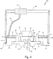
- FIG. 4 is a schematic sectional view diagram of pressure sensor 10B with fully exposed diaphragm 12, where an isolator is fully integrated with a diaphragm wafer, resulting in integrated wafer 56.
- Pressure sensor 10B in FIG. 4 is an alternative embodiment of pressure sensor 10 in FIG. 2 which is not covered by the present invention.
- Pressure sensor 10B in FIG. 4 contains fully integrated wafer 56, which is an isolator integrated with a diaphragm wafer. Both the isolator and the diaphragm wafer are made of silicon, and are one continuous piece.
- isolator portion 57 is a thin, flexible extension of integrated wafer 56.
- Integrated wafer 56 is large enough to allow bending and flexing of isolator portion 57, but prevent unwanted bending of diaphragm 12 in the center portion of the continuous silicon piece.
- Integrated wafer 56 allows for more flexibility of material in creation of pressure sensor 10B.
- FIGS. 5 , 6A and 6B show pressure sensor 60 according to claim 1 of the present invention, which is in a different configuration than pressure sensor 10 of FIG. 2 .
- FIG. 5 is a schematic sectional view of pressure sensor 60.
- Pressure sensor 60 includes housing 64, isolator 66, diaphragm wafer 68, electrical feedthrough pins 70, non-conductive seals 72, pressure sensing element 74, bond pads 76, 78, pin 80, and wire-bonds 82.
- Housing 62 encircles all other components of pressure sensor 60.
- Weld feature 64 is part of housing 62.
- Isolator 66 is attached to the inside of housing 62, and diaphragm wafer 68 is attached to isolator 66.
- Electrical feedthrough pins 70 are connected to diaphragm wafer 68 through a series of bond pads 76, 78 and wire-bonds 82. Electrical feedthrough pins run through the side of housing 62 and are sealed to housing 62 through non-conductive seals 72.
- FIGS. 6A and 6B are perspective diagrams of pressure sensor 60 from both sides.
- FIG. 6A shows housing 62, weld feature 64 of housing 62, isolator 66, diaphragm wafer 68, diaphragm 69, electrical feedthrough pins 70, and seal 72.
- FIG. 6B shows the opposite side of FIG. 6A , and shows housing 62, weld feature 64, isolator 66, electrical feedthrough pins 70, seals 72, pressure sensing element 74, wire-bond pads 76, 78, pin 80, and wire-bonds 82. All three figures will be discussed together.
- Pressure sensor 60 can be deployed in "dirty" environments to detect the pressure of process fluid. Pressure sensor 60 detects process fluid pressure (P) when the fluid pushes against diaphragm 69, located in the center of diaphragm wafer 68. Diaphragm 69 is fully exposed to the environment. Pressure sensing element 74, on the opposite side of diaphragm, will sense the pressure and convert it to useable electrical signals. Pressure sensing element 74 can be a Wheatstone bridge or capacitive plates.
- the isolator 66 functions similarly to isolator 18 of FIG. 2 .
- Isolator 66 is a thin material designed to reduce lateral stresses, and is preferably made of silicon.
- Isolator 66 is bonded to diaphragm wafer 68, and then bonded to housing 62.
- the outer diameter of isolator 66 is coated so it can bond to housing 62.
- Isolator 66 has a chemically milled hole to allow wiring access. Isolator 66 reduces lateral stresses to isolate the diaphragm wafer 68 (including diaphragm 69 and pressure sensing element 74), and will flex and bend with those stresses.
- the signal to pressure sensing element 74 will not be reduced, as diaphragm 69 is directly exposed to the process fluid and will move with the pressure of the process fluid.
- Isolator 66 is in direct contact with housing 62, and also reduces stresses associated with that connection.
- Housing 62 is preferably an alloy with a coefficient of thermal expansion matched to silicon. If housing 62 is left open to the environment (as pictured), it can be used in a gage configuration. Alternatively, a back plate can be welded to housing 62 to create a vacuum environment for use to determine absolute pressure. Housing 62 contains a weld feature 64 that allows the entire pressure sensor 60 to be inserted into a pneumatic or hydraulic fitting, or another adapter, and circumferentially seam welded shut.
- Housing 62 must allow for electrical feedthrough pins 70, as there are no internal printed circuit boards in this embodiment.
- Electrical feedthrough pins 70 are preferably made of an iron-nickel alloy, and provide electrical conductivity from pressure sensing element 74 to transducer electronics (not pictured). Each pressure sensing element 74 will require four pins 70 for each corner of a Wheatstone bridge.
- Electrical feedthrough pins 70 are electrically insulated by non-conductive seals 72, which may be made of borosilicate glass, to housing 62.
- Pressure sensing element 74 is electrically connected to electrical feedthrough pins via wire-bond pads 76, 78 and wire-bonds 82. Wire-bond pads are optimally an aluminum or gold alloy.
- Bond pads 76 are a thin coating which provides electrical continuity and wire bond connection between pressure sensing element 74 and electrical feedthrough pins 70.
- Bond pads 78 are a thin coating which provides electrical continuity between the Wheatstone bridge of pressure sensing element 74, wire-bonds 82, and electrical feedthrough pins 70.
- Gold plated iron-nickel alloy pins 80 are flats on the ends of electrical feedthrough pins 70 that provide flat surfaces for wire-bond attachment to transducer electronics, where the pressure signal detected by diaphragm 69 and pressure sensing element 74 is transmitted for interpretation.
- FIG. 7 shows a method of making a pressure sensor according to claim 10 of the present invention.
- a diaphragm wafer is fabricated.
- the diaphragm wafer includes a fluid contact surface, a diaphragm located along the surface and configured to deflect in response to pressure, a sensing element that is responsive to deflection of the diaphragm, and a support portion, where the support portion and the diaphragm define a cavity.
- the diaphragm wafer is preferably made of silicon, and the pressure sensing element may consist of capacitive plates or a piezoresistive device.
- an isolator is fabricated.
- the isolator is preferably made of an iron-nickel alloy, silicon, glass, ceramic, stainless foil, or some combination thereof, such that the isolator is configured to absorb lateral stresses.
- a housing is fabricated next.
- the housing includes a housing end and a sidewall, and may optionally include a back plate.
- the housing may be made of an iron-nickel alloy, or of stainless steel.
- the isolator is then connected to the housing. Specifically, an outer portion of the isolator is attached to the housing end. Then, the diaphragm wafer is attached to the isolator by attaching the support portion of the diaphragm wafer to the isolator.
- Method 86 can be completed in two optional routes for completing creation of the pressure sensor.
- a topping wafer and an over-pressure support are fabricated.
- the topping wafer is preferably made of silicon or silicon-glass.
- the topping wafer is bonded to the diaphragm wafer by frit. Then, hundreds of individual sensor die are sawn out of the wafer. After this attachment, the die (comprising the topping wafer and the diaphragm wafer) is attached to the isolator.
- printed circuit boards are attached to the housing, and are attached to the diaphragm wafer through wire-bonds, the printed circuit boards are then connected to a connector through wires. This is followed by the attachment of the over-pressure support to the housing through a cross-bar or anchor, and to the topping wafer through epoxy. Finally, the housing end is welded to the sidewall and a back plate to complete the housing.
- the housing should be an iron-nickel alloy.
- the second method does not require the use of a topping wafer, over pressure support, or printed circuit boards.
- the isolator contains one or more chemically milled holes through which electrical feedthrough pins are run. The holes are then sealed, optionally with borosilicate glass seals. After the attachment of the diaphragm to the isolator, the diaphragm is bonded to the one or more iron-nickel alloy electrical feedthrough pins, through a series of bond pads and wire-bonds. The feedthrough pins are then connected to transducer electronics.
- the disclosed pressure sensor design has several benefits.
- the removal of an oil-filled isolator eliminates costly and bulky materials used in prior art. Glass pins are no longer required to feedthrough an electrical signal.
- the placement of an exposed diaphragm allows for the elimination of wells and cavities in which foreign object damage can occur. Overall, the cost of the product is reduced, the manufacturing process is better, and the performance of the pressure sensor is improved.
Description
- Pressure sensors must be built for use in a variety of environments. Often, the fluid of interest is not a "clean" fluid, but instead is in a harsh environment, which may contain foreign object debris. Pressure sensors for use in harsh environments must be designed to avoid destruction and clogging of the pressure sensing die used in such environments.
- Traditionally, harsh environment pressure sensors used fluid separation membranes to separate the pressure sensing die from the measurement environment where the process fluid of interest was located. The fluid separation membrane, placed between the process fluid field and the sensing die, transfers the pressure of the process fluid to the pressure sensing die in the device. However, to contain isolation oil, these designs relied on expensive hermetically-sealed glassed-in pins to provide feedthrough of electrical signals. Traditional designs also created unwanted pockets in the path to the sensing die, clogging the pressure sensor with external, harsh environment fluid, and foreign objects within the pockets of the pressure sensor. The large coefficient of thermal expansion of the oil in conjunction with the compliance of the isolator created performance errors with pressure readings in such sensors. Additionally, the remote distance of the pressure sensing die itself from the process fluid, due to the space of the oil-filled isolator, created performance errors and delayed response with pressure readings.
-
EP 2 816 A1 US 2014/238141 A1 ,EP 0553725 A2 ,US 2015/059489 A1 ,US 5945605 A andUS 5062302 A all relate to pressure sensors. - According to claim 1 of the present invention a pressure sensor and according to
claim 10 of the present invention a method of manufacturing a pressure sensor are disclosed. -
-
FIG. 1A is a schematic diagram of a traditional pressure sensor assembly as shown in prior art. -
FIG. 1B is a schematic diagram of a traditional pressure sensor assembly in an oil-filled embodiment as shown in prior art. -
FIG. 2 is a schematic diagram of a pressure sensor with a fully exposed diaphragm according to claim 1 of the present invention. -
FIG. 3 is a schematic diagram of a pressure sensor with a fully exposed diaphragm in a gage pressure configuration according to claim 1 of the present invention. -
FIG. 4 is a schematic diagram with a fully exposed diaphragm including an integral silicon isolator which is not covered by the present invention. -
FIG. 5 is a schematic diagram of another embodiment of a pressure sensor with a fully exposed diaphragm, in a configuration with electrical feedthrough pins according to claim 1 of the present invention -
FIG. 6A is a perspective diagram of the pressure sensor inFIG. 5 according to claim 1 of the present invention -
FIG. 6B is a perspective diagram of the pressure sensor inFIG. 5 from the side oppositeFIG. 6A according to claim 1 of the present invention. -
FIG. 7 is a flow chart showing a method of making a pressure sensor according toclaim 10 of the present invention. - The present invention disclosure according to claim 1 describes a pressure sensor that eliminates the need for fluid separation membranes and oil-filled cavities, allows for a sensing die which is open to the environment, and is an easily drainable system. Moreover, the design does not require glassed-in pins to send electrical signals; instead wire-bonds or electrical feedthrough pins can be used to directly access the pressure sensing die. The design utilizes an oil-free isolator which reduces cost and size of the pressure sensor, while increasing efficiency in pressure reading.
-
FIG. 1A is a schematic sectional view diagram ofpressure sensor assembly 1A as found in prior art.Pressure sensor assembly 1A includeshousing 2A,pedestal isolator 3A,backing wafer 4A,connections 5A,diaphragm wafer 6A,topping wafer 7, and electrical feedthrough pin 0A.Diaphragm wafer 6A contains a diaphragm and a pressure-sensing element. In this traditional configuration,housing 2A is stainless steel (or similar) housing which encloses the other elements ofpressure sensor assembly 1A.Pedestal isolator 3A, which is the traditional version of a pedestal in a harsh environment pressure sensor, is attached tohousing 2A and backingwafer 4A.Diaphragm wafer 6A is anchored to backingwafer 4A, and toppingwafer 7 is rigidly secured todiaphragm wafer 6A.Connectors 5A are attached to the surface ofdiaphragm wafer 6A and electrical feedthrough pins 0A.Diaphragm wafer 6A is removed from stress associated by temperature changes ofhousing 2A, bypedestal isolator 3A andbacking wafer 4A. - In this apparatus, as presented in prior art, foreign object damage occurs within the passage of
pedestal isolator 3A, backingwafer 4A, anddiaphragm wafer 6A. This design suffers from particulate susceptibility. Moreover, the remote distance of the pressure sensing die itself from the process fluid due to the space ofpedestal 3A creates performance errors and delayed response with pressure readings in such sensors. -
FIG. 1B is a schematic sectional view diagram ofpressure sensor assembly 1B, as described in prior art.Pressure sensor assembly 1B includeshousing 2B,pedestal isolator 3B,backing wafer 4B,connections 5B, diaphragm wafer 6B, oil filledcavity 8,oil fill tube 9, electrical feedthrough pins 0B, andoil separation membrane 100.Housing 2B enclosespedestal isolator 3B,backing wafer 4B,connections 5B, and diaphragm wafer 6B.Pedestal isolator 3B is attached tohousing 2B and backingwafer 4B. Diaphragm wafer 6B, which contains a diaphragm and a pressure sensing element, is attached to backingwafer 4B.Connections 5B attach to diaphragm wafer 6B and to electrical feedthrough pins 0B. Feedthrough pins 0B run throughhousing 2B for connection to electronics (not pictured). On an end ofhousing 2B closest diaphragm wafer 6B,fluid separation membrane 100 enclosespressure sensing assembly 1B, creating oil-filledcavity 8, and prevents exposure of diaphragm wafer 6B to external process fluid. The entire internal compartment ofpressure sensor assembly 1B is oil-filled to transfer pressure P of external process fluid to diaphragm wafer 6B. - Oil-filled
cavity 8 is the most basic fix to the problems associated withpressure sensor assembly 1A. The oil that is filled intopressure sensor assembly 1B is as inert and clean as possible, with thermal expansion characteristics to reduce error regarding temperature. However, the use of oil-filledcavity 8 drastically increases the amount of space required in the apparatus. Expensive hermetically-sealed glassed-in pins must be included to provide feedthrough of electrical signals outside the oil-filled internal space. The present invention provides an alternative apparatus which solves these problems. -
FIG. 2 is a schematic sectional view diagram ofpressure sensor 10 according to claim 1 of the present invention, which includespressure sensing element 11, fully exposeddiaphragm 12, afluid contact surface 13, die 14, overpressure support 16,isolator 18,housing 20,connector 22,wires 24 and printedcircuit boards 26. Die 14 includes topping wafer 28 (with over pressure stop 29) and diaphragm wafer 30.Diaphragm wafer 30 includespressure sensing element 11, fully exposeddiaphragm 12,fluid contact surface 13, andsupport portion 34.Diaphragm 12 andsupport portion 34 definecavity 32.Housing 20 includesmain housing end 36,main housing sidewall 38 andback plate 40. -
Main housing end 36 is connected toisolator 18 throughbraze joints 42.Isolator 18 is connected to die 14 bybonds 44 to supportportion 34 ofdiaphragm wafer 30. Toppingwafer 28 is connected to the internal end ofdiaphragm wafer 30 byfrit 46.Over-pressure support 16 is attached to the opposite end of toppingwafer 28 withepoxy 48 and is rigidly attached tomain housing chamber 20 through a cross-bar or other anchor (not pictured).Die 14 is connected to printedcircuit boards 26 by wire-bonds 50, which are directly connected to sensingelement 11 ofdiaphragm wafer 30. Printedcircuit boards 26 are attached tomain housing end 36 andwires 24.Wires 24 connect printedcircuit boards 26 toconnector 22, which is placed alongback plate 40. Backplate 40 is welded tosidewall 38, which is welded tomain housing end 36. Backplate 40,sidewall 38, andmain housing end 36, typically made of stainless steel, make uphousing 20, which surrounds die 14,over-pressure support 16 and printedcircuit boards 26. -
Pressure sensor 10 can be deployed in a harsh environment with a process fluid, and is configured to sense the absolute pressure of the process fluid. The process fluid may be a gas, liquid, or both, and may contain small solid particulates.Pressure sensor 10 detects process fluid pressure (P) when the process fluid entersdiaphragm cavity 32 and is sensed bydiaphragm 12. In some embodiments,diaphragm wafer 30 is silicon.Diaphragm 12, located in the center portion ofdiaphragm wafer 30, withfluid contact surface 13 facingcavity 32, is fully exposed to the harsh environment.Diaphragm 12 deflects in response to the pressure (P) of the process fluid. Deflection ofdiaphragm 12 is detected bypressure sensing element 11.Pressure sensing element 11 can be, for example, a piezoresistive Wheatstone bridge or capacitive plates. Toppingwafer 28, which is connected todiaphragm wafer 30 byfrit 46, provides reference pressure to sensingelement 11. Toppingwafer 28 is preferably made of silicon or glass (such as a borosilicate glass). InFIG. 2 , the reference pressure, between toppingwafer 28 anddiaphragm wafer 30, is a vacuum. This allows forpressure sensor 10 to detect absolute pressure of the process fluid. - According to claim 1 of the present invention the topping
wafer 28 includes overpressure stop 29, which preventsdiaphragm 12 from bursting. Over pressure stop 29 in toppingwafer 28 limits the length that diaphragm 12 can deflect. In addition, overpressure support 16 reinforces the toppingwafer 28 to prevent both thediaphragm 12 and die 14 from bursting if the pressure of the process fluid is too high. -
Over-pressure support 16 is attached to die 14 to avoid over-pressurization ofdie 14.Over-pressure support 16 is rigidly attached to both toppingwafer 28 andmain housing chamber 20 to maintain stability.Over-pressure support 16 can be attached tomain housing 20 via a cross-bar or other means to anchorover-pressure support 16 tomain housing 20. The rigid attachment ofover-pressure support 16 tohousing 20, and the attachment ofisolator 18 tohousing 20 allows fordie 14 to be rigidly placed insidemain housing 20.Die 14 is attached firmly toover-pressure support 16, which is secured tomain housing 20; additionally, die 14 is attached toisolator 18, which is firmly attached tomain housing 20. Thus, die 14 is securely in place withinpressure sensor 10 and is not easily dislodged. Instead of toppingwafer 28 anddiaphragm wafer 30 moving with pressure, only diaphragm 12 located incavity 32 will deflect from pressure due to the process fluid.Over-pressure support 16 prevents die 14 from bursting if the pressure of the process fluid is too high. -
Isolator 18 is a thin material designed to absorb lateral stresses.Isolator 18 can be made of an iron-nickel alloy, silicon, glass, ceramic, stainless steel foil or a combination thereof. - According to claim 1 of the present invention the
isolator 18 attaches inwardly frommain housing end 36 todiaphragm wafer 30.Isolator 18 absorbs lateral stresses and protects die 14 from taking those stresses.Isolator 18 will flex with lateral stresses, protectingdiaphragm 12.Diaphragm 12 will deflect pressure P from the process fluid of interest, andpressure sensing element 11 will detect that pressure. Pressure from the process fluid will also be applied toisolator 18, andisolator 18 will move with that pressure. However, the signal determined by die 14 will not be reduced, asdiaphragm 12 is directly exposed to the process fluid and will move with the pressure P of the process fluid.Isolator 18 is directly connected tohousing end 36, and further absorbs thermal stresses associated with that connection. - From the point of attachment of
isolator 18 todiaphragm wafer 30,diaphragm wafer cavity 32 converges to an apex, wherediaphragm 12 is located oncontact surface 13. The divergence ofcavity 32 as it approaches the harsh environment ensures thatdiaphragm 12 is fully exposed to the process fluid, making the readings ofpressure sensing element 11 more accurate. As the fluid enterscavity 32, there are no pockets, corners, or pathways in which particles contained in dirty fluid get "stuck" or trapped. Because the sensor is fully exposed and has no cavities able to contain particulates in the process fluid, the particulates self-shed, do not accumulate, and do not interfere with the pressure measurement. - In prior art, the existence of such cavities or pockets made pressure sensing assemblies difficult to drain. Over time, build-up of dirty fluid in cavities would cause errors in pressure readings. But in the present invention, there are no unwanted cavities in or near
diaphragm 12. For this reason, process fluid cannot get stuck in pockets in or neardiaphragm 12 orisolator 18. The process fluid is easily drainable fromcavity 32, as the entrance throughisolator 18 is wider thancavity 32 anddiaphragm 12. - Neither can foreign object damage occur. While prior designs allowed for foreign object damage from process fluids in harsh environments, there is nowhere in this design for such objects to get lodged.
Diaphragm 12 is fully exposed to the harsh environment and the process fluid. This makespressure sensor 10 easily drainable. Additionally, this reduces error in pressure sensing, as the die is in direct contact with the environment it is measuring. - Printed
circuit boards 26 are attached directly to die 14 via wire-bonds 50. When diaphragm 12 reacts to the pressure of the process fluid, it transmits a signal through wire-bonds 50 to printedcircuit boards 26. In turn, printedcircuit boards 26 transmits the signal throughwires 24 toconnector 22, where the signal is interpreted and converted to a readable pressure measurement. -
FIG. 3 is a schematic sectional view diagram ofpressure sensor 10A with fully exposeddiaphragm 12, in a gage pressure configuration according to claim 1 of the present invention. - The components of
FIG. 3 are the same as those described in reference toFIG. 2 , and are connected in the same fashion, except where otherwise described here. InFIG.3 ,pressure sensor 10A is configured to sense gage pressure of the process fluid, as opposed to absolute pressure.Tubing 58 runs from an external atmosphere throughback plate 40, overpressure support 16, and toppingwafer 28 to provide an atmospheric pressure reference todiaphragm 12. - According to claim 1 of the present invention the
pressure sensor 10A is set up for a gage configuration where the pressure between toppingwafer 28 anddiaphragm wafer 30 is equal to reference pressure, typically atmospheric pressure (as opposed to the vacuum inFIG. 2 ). This is not a true differential set up, because the reference side ofpressure sensor 10A, next to backplate 40 ofhousing chamber 20 is a "clean" side; it is not immersed in the harsh environment which contains the fluid of interest. The other side ofpressure sensor 10A, which containsisolator 18 anddiaphragm 12, is exposed to the harsh environment and the process fluid. -
FIG. 4 is a schematic sectional view diagram ofpressure sensor 10B with fully exposeddiaphragm 12, where an isolator is fully integrated with a diaphragm wafer, resulting inintegrated wafer 56.Pressure sensor 10B inFIG. 4 is an alternative embodiment ofpressure sensor 10 inFIG. 2 which is not covered by the present invention. - The components of
FIG. 4 are the same as those described in reference toFIG. 2 , and are connected in the same fashion, except where otherwise described here.Pressure sensor 10B inFIG. 4 contains fully integratedwafer 56, which is an isolator integrated with a diaphragm wafer. Both the isolator and the diaphragm wafer are made of silicon, and are one continuous piece. Here,isolator portion 57 is a thin, flexible extension ofintegrated wafer 56.Integrated wafer 56 is large enough to allow bending and flexing ofisolator portion 57, but prevent unwanted bending ofdiaphragm 12 in the center portion of the continuous silicon piece.Integrated wafer 56 allows for more flexibility of material in creation ofpressure sensor 10B. -
FIGS. 5 ,6A and6B showpressure sensor 60 according to claim 1 of the present invention, which is in a different configuration thanpressure sensor 10 ofFIG. 2 .FIG. 5 is a schematic sectional view ofpressure sensor 60.Pressure sensor 60 includeshousing 64,isolator 66,diaphragm wafer 68, electrical feedthrough pins 70,non-conductive seals 72,pressure sensing element 74,bond pads pin 80, and wire-bonds 82.Housing 62 encircles all other components ofpressure sensor 60.Weld feature 64 is part ofhousing 62.Isolator 66 is attached to the inside ofhousing 62, anddiaphragm wafer 68 is attached toisolator 66. Electrical feedthrough pins 70 are connected todiaphragm wafer 68 through a series ofbond pads bonds 82. Electrical feedthrough pins run through the side ofhousing 62 and are sealed tohousing 62 through non-conductive seals 72. -
FIGS. 6A and6B are perspective diagrams ofpressure sensor 60 from both sides.FIG. 6A showshousing 62, weld feature 64 ofhousing 62,isolator 66,diaphragm wafer 68,diaphragm 69, electrical feedthrough pins 70, andseal 72.FIG. 6B shows the opposite side ofFIG. 6A , and showshousing 62,weld feature 64,isolator 66, electrical feedthrough pins 70, seals 72,pressure sensing element 74, wire-bond pads pin 80, and wire-bonds 82. All three figures will be discussed together. -
Pressure sensor 60 can be deployed in "dirty" environments to detect the pressure of process fluid.Pressure sensor 60 detects process fluid pressure (P) when the fluid pushes againstdiaphragm 69, located in the center ofdiaphragm wafer 68.Diaphragm 69 is fully exposed to the environment.Pressure sensing element 74, on the opposite side of diaphragm, will sense the pressure and convert it to useable electrical signals.Pressure sensing element 74 can be a Wheatstone bridge or capacitive plates. - According to claim 1 of the present invention the isolator 66 functions similarly to
isolator 18 ofFIG. 2 .Isolator 66 is a thin material designed to reduce lateral stresses, and is preferably made of silicon.Isolator 66 is bonded todiaphragm wafer 68, and then bonded tohousing 62. The outer diameter ofisolator 66 is coated so it can bond tohousing 62.Isolator 66 has a chemically milled hole to allow wiring access.Isolator 66 reduces lateral stresses to isolate the diaphragm wafer 68 (includingdiaphragm 69 and pressure sensing element 74), and will flex and bend with those stresses. However, the signal to pressuresensing element 74 will not be reduced, asdiaphragm 69 is directly exposed to the process fluid and will move with the pressure of the process fluid.Isolator 66 is in direct contact withhousing 62, and also reduces stresses associated with that connection. -
Housing 62 is preferably an alloy with a coefficient of thermal expansion matched to silicon. Ifhousing 62 is left open to the environment (as pictured), it can be used in a gage configuration. Alternatively, a back plate can be welded tohousing 62 to create a vacuum environment for use to determine absolute pressure.Housing 62 contains aweld feature 64 that allows theentire pressure sensor 60 to be inserted into a pneumatic or hydraulic fitting, or another adapter, and circumferentially seam welded shut. -
Housing 62 must allow for electrical feedthrough pins 70, as there are no internal printed circuit boards in this embodiment. Electrical feedthrough pins 70 are preferably made of an iron-nickel alloy, and provide electrical conductivity frompressure sensing element 74 to transducer electronics (not pictured). Eachpressure sensing element 74 will require fourpins 70 for each corner of a Wheatstone bridge. Electrical feedthrough pins 70 are electrically insulated bynon-conductive seals 72, which may be made of borosilicate glass, tohousing 62.Pressure sensing element 74 is electrically connected to electrical feedthrough pins via wire-bond pads bonds 82. Wire-bond pads are optimally an aluminum or gold alloy.Bond pads 76 are a thin coating which provides electrical continuity and wire bond connection betweenpressure sensing element 74 and electrical feedthrough pins 70.Bond pads 78 are a thin coating which provides electrical continuity between the Wheatstone bridge ofpressure sensing element 74, wire-bonds 82, and electrical feedthrough pins 70. Gold plated iron-nickel alloy pins 80 are flats on the ends of electrical feedthrough pins 70 that provide flat surfaces for wire-bond attachment to transducer electronics, where the pressure signal detected bydiaphragm 69 andpressure sensing element 74 is transmitted for interpretation. -
FIG. 7 shows a method of making a pressure sensor according to claim 10 of the present invention. First, a diaphragm wafer is fabricated. The diaphragm wafer includes a fluid contact surface, a diaphragm located along the surface and configured to deflect in response to pressure, a sensing element that is responsive to deflection of the diaphragm, and a support portion, where the support portion and the diaphragm define a cavity. The diaphragm wafer is preferably made of silicon, and the pressure sensing element may consist of capacitive plates or a piezoresistive device. - Next, an isolator is fabricated. The isolator is preferably made of an iron-nickel alloy, silicon, glass, ceramic, stainless foil, or some combination thereof, such that the isolator is configured to absorb lateral stresses. A housing is fabricated next. The housing includes a housing end and a sidewall, and may optionally include a back plate. The housing may be made of an iron-nickel alloy, or of stainless steel. The isolator is then connected to the housing. Specifically, an outer portion of the isolator is attached to the housing end. Then, the diaphragm wafer is attached to the isolator by attaching the support portion of the diaphragm wafer to the isolator.
- Method 86 can be completed in two optional routes for completing creation of the pressure sensor. To create
pressure sensor 10 fromFIG. 2 , a topping wafer and an over-pressure support are fabricated. The topping wafer is preferably made of silicon or silicon-glass. The topping wafer is bonded to the diaphragm wafer by frit. Then, hundreds of individual sensor die are sawn out of the wafer. After this attachment, the die (comprising the topping wafer and the diaphragm wafer) is attached to the isolator. - Next, printed circuit boards are attached to the housing, and are attached to the diaphragm wafer through wire-bonds, the printed circuit boards are then connected to a connector through wires. This is followed by the attachment of the over-pressure support to the housing through a cross-bar or anchor, and to the topping wafer through epoxy. Finally, the housing end is welded to the sidewall and a back plate to complete the housing.
- Alternatively, to create
pressure sensor 60 fromFIG. 5 , the housing should be an iron-nickel alloy. The second method does not require the use of a topping wafer, over pressure support, or printed circuit boards. In this method, the isolator contains one or more chemically milled holes through which electrical feedthrough pins are run. The holes are then sealed, optionally with borosilicate glass seals. After the attachment of the diaphragm to the isolator, the diaphragm is bonded to the one or more iron-nickel alloy electrical feedthrough pins, through a series of bond pads and wire-bonds. The feedthrough pins are then connected to transducer electronics. - The disclosed pressure sensor design has several benefits. The removal of an oil-filled isolator eliminates costly and bulky materials used in prior art. Glass pins are no longer required to feedthrough an electrical signal. Moreover, the placement of an exposed diaphragm allows for the elimination of wells and cavities in which foreign object damage can occur. Overall, the cost of the product is reduced, the manufacturing process is better, and the performance of the pressure sensor is improved.
Claims (12)
- A pressure sensor (10,10A, 60) comprising:a housing (20, 62, 64);a diaphragm wafer (30, 68) comprising:a fluid contact surface (13),a diaphragm (12, 69) located along the surface and configured to deflect in response to pressure;a pressure sensing element (11, 74) that is responsive to deflection of the diaphragm (12, 69); anda support portion (34), wherein the support portion and the diaphragm (12, 69) define a cavity (32);an isolator (18, 66) extending laterally between the diaphragm wafer (30, 68) and the housing, wherein the isolator is configured to absorb lateral stresses, wherein the isolator (18, 66) is connected between the support portion of the diaphragm wafer and the housing (20, 62, 64) such that an inner portion of the isolator (18, 66) is attached to the support portion and an outer portion of the isolator is attached to the housing, and the isolator (18, 66) is parallel to the fluid contact surface;a topping wafer (28) attached to the diaphragm wafer (30, 68) and configured to provide reference pressure, and the pressure sensor (10, 60) further comprising an over pressure support (16) rigidly attached to the housing (20, 62, 64) and the topping wafer (28), and configured to prevent over-pressurization of the pressure sensor (10, 60);an over pressure stop (29) in the topping wafer (28) configured to limit deflection of the diaphragm (12, 69); andtubing (58) configured to allow gage pressure measurements where the pressure between the topping wafer (28) and the diaphragm wafer (30, 68) is equal to the reference pressure.
- The pressure sensor of claim 1, wherein the housing (20,62, 64) comprises a housing end and a sidewall, and wherein the housing (20,62, 64) includes a back plate (40).
- The pressure sensor of claim 1, wherein the housing (20,62, 64) includes a weld feature configured to allow attachment of the pressure sensor (10,10A,60) to transducer electronics.
- The pressure sensor of any preceding claim, wherein the isolator (18,66) attaches to the diaphragm wafer (30,68) at a widest end of the cavity (32) and the cavity (32) converges to an apex.
- The pressure sensor of any claims 1 - 3, wherein the cavity (32) retains a uniform cross-sectional area.
- The pressure sensor of any preceding claim, wherein the diaphragm wafer (30,68) and the isolator (18,66) are a monolithic structure.
- The pressure sensor of any preceding claim, wherein the isolator (18,66) is coated such that it can be bonded to the housing (20,62, 64) and attached to the diaphragm wafer (30,68).
- The pressure sensor of any preceding claim, further comprising:a connector (22) attached to the housing (20,62, 64);one or more wire-bonds (82); andone or more printed circuit boards (26) attached to the connector (22) through at least one wire (24), and attached to the diaphragm wafer (68) through the one or more wire-bonds (82).
- The pressure sensor of any preceding claim, further comprising at least one electrical feedthrough pin (70) that runs through the housing (20,62, 64) and is electrically connected to the pressure sensing element (11,74), and the pressure sensor (10,10A,60) further comprising a seal (72), which is configured to electrically insulate the at least one electrical feedthrough pin (70) where it runs through the housing (20,62,64).
- A method for creating a pressure sensor (10,10A,60), the method comprising:fabricating a diaphragm wafer (30, 68) comprising a fluid contact surface (13), a diaphragm (12, 69) located along the surface and configured to deflect in response to pressure, a pressure sensing element (11, 74) that is responsive to deflection of the diaphragm (12, 69), and a support portion (34),wherein the support portion and the diaphragm (12, 69) define a cavity (32);fabricating an isolator (18, 66) configured to absorb lateral stresses;fabricating a housing (20, 62, 64);connecting the isolator (18, 66) to the housing (20, 62, 64); andattaching the diaphragm wafer (30, 68) to the isolator (18, 66), such that the support portion of the diaphragm wafer (30, 68) is attached to an inner portion of the isolator (18, 66), an outer portion of the isolator (18, 66) is attached to the housing (20, 62, 64), and the fluid contact surface of the diaphragm wafer (30, 68) is parallel to the isolator,wherein the isolator (18, 66) extends laterally between the diaphragm wafer (30, 68) and the housing;fabricating a topping wafer (28) configured to provide reference pressure;fabricating an over-pressure support (16);attaching a topping wafer (28) to the diaphragm wafer (30, 68);attaching an over-pressure support (16) to the topping wafer (28);rigidly attaching the over-pressure support (16) to the housing (20, 62, 64); the topping wafer (28) configured to prevent over-pressurization of the pressure sensor (10, 60);providing an over pressure stop (29) in the topping wafer (28) configured to limit deflection of the diaphragm (12, 69); andproviding tubing (58) configured to allow gage pressure measurements where the pressure between the topping wafer (28) and the diaphragm wafer (30, 68) is equal to the reference pressure.
- The method of claim 10, and further comprising:attaching at least one printed circuit board (26) to the housing (20,62,64);attaching the at least one printed circuit board (26) to the diaphragm wafer (30,68) through at least one wire-bond (82);connecting the at least one printed circuit boards (26) to a connector (22) through at least one wire (24); andattaching the connector (22) along the housing (20,62, 64).
- The method of claim 10 or 11, and further comprising:chemically milling at least one hole in the isolator (18,66);bonding the pressure sensing element (11,74) of the diaphragm wafer (30,68) to at least one electrical feedthrough pin (70);running the at least one electrical feedthrough pin (70) through the at least one hole in the isolator (18,66);sealing the at least one hole; andconnecting the at least one electrical feedthrough pin (70) to a transducer electronics.
Applications Claiming Priority (1)
| Application Number | Priority Date | Filing Date | Title |
|---|---|---|---|
| US15/041,243 US10101234B2 (en) | 2016-02-11 | 2016-02-11 | Open diaphragm harsh environment pressure sensor |
Publications (2)
| Publication Number | Publication Date |
|---|---|
| EP3205998A1 EP3205998A1 (en) | 2017-08-16 |
| EP3205998B1 true EP3205998B1 (en) | 2022-10-26 |
Family
ID=58009729
Family Applications (1)
| Application Number | Title | Priority Date | Filing Date |
|---|---|---|---|
| EP17155350.6A Active EP3205998B1 (en) | 2016-02-11 | 2017-02-09 | Open diaphragm harsh environment pressure sensor |
Country Status (2)
| Country | Link |
|---|---|
| US (1) | US10101234B2 (en) |
| EP (1) | EP3205998B1 (en) |
Families Citing this family (4)
| Publication number | Priority date | Publication date | Assignee | Title |
|---|---|---|---|---|
| US10065853B2 (en) * | 2016-05-23 | 2018-09-04 | Rosemount Aerospace Inc. | Optimized epoxy die attach geometry for MEMS die |
| CN209326840U (en) | 2018-12-27 | 2019-08-30 | 热敏碟公司 | Pressure sensor and pressure transmitter |
| US11834328B2 (en) * | 2020-06-29 | 2023-12-05 | Invensense, Inc. | Semiconductor package with built-in vibration isolation, thermal stability, and connector decoupling |
| DE102022104697A1 (en) * | 2022-02-28 | 2023-08-31 | Tdk Electronics Ag | Media separated sensor |
Family Cites Families (17)
| Publication number | Priority date | Publication date | Assignee | Title |
|---|---|---|---|---|
| US5062302A (en) | 1988-04-29 | 1991-11-05 | Schlumberger Industries, Inc. | Laminated semiconductor sensor with overpressure protection |
| US5285690A (en) | 1992-01-24 | 1994-02-15 | The Foxboro Company | Pressure sensor having a laminated substrate |
| US5945605A (en) | 1997-11-19 | 1999-08-31 | Sensym, Inc. | Sensor assembly with sensor boss mounted on substrate |
| US20010001550A1 (en) * | 1998-11-12 | 2001-05-24 | Janusz Bryzek | Integral stress isolation apparatus and technique for semiconductor devices |
| US6550337B1 (en) * | 2000-01-19 | 2003-04-22 | Measurement Specialties, Inc. | Isolation technique for pressure sensing structure |
| GB2441785B (en) * | 2006-09-15 | 2009-08-12 | Schlumberger Holdings | Ruggedized pressure sensor |
| US7775119B1 (en) * | 2009-03-03 | 2010-08-17 | S3C, Inc. | Media-compatible electrically isolated pressure sensor for high temperature applications |
| US20130130424A1 (en) | 2010-05-03 | 2013-05-23 | S3C, Inc. | Process for minimizing chipping when separating mems dies on a wafer |
| US8371176B2 (en) * | 2011-01-06 | 2013-02-12 | Honeywell International Inc. | Media isolated pressure sensor |
| US8833172B2 (en) * | 2012-06-27 | 2014-09-16 | Continental Automotive Systems, Inc | Pressure sensing device with stepped cavity to minimize thermal noise |
| US9116057B2 (en) | 2013-02-27 | 2015-08-25 | Honeywell International Inc. | Integrated reference vacuum pressure sensor with atomic layer deposition coated input port |
| US10151647B2 (en) | 2013-06-19 | 2018-12-11 | Honeywell International Inc. | Integrated SOI pressure sensor having silicon stress isolation member |
| DE102013217349A1 (en) * | 2013-08-30 | 2015-03-05 | Robert Bosch Gmbh | Micromechanical sensor arrangement and corresponding manufacturing method |
| US9013013B1 (en) * | 2013-12-06 | 2015-04-21 | Infineon Technologies Ag | Pressure sensor package having a stacked die arrangement |
| US9310267B2 (en) * | 2014-02-28 | 2016-04-12 | Measurement Specialities, Inc. | Differential pressure sensor |
| JP6034818B2 (en) * | 2014-03-04 | 2016-11-30 | アズビル株式会社 | Pressure sensor chip |
| US9212054B1 (en) | 2014-10-15 | 2015-12-15 | DunAn Sensing, LLC | Pressure sensors and methods of making the same |
-
2016
- 2016-02-11 US US15/041,243 patent/US10101234B2/en active Active
-
2017
- 2017-02-09 EP EP17155350.6A patent/EP3205998B1/en active Active
Also Published As
| Publication number | Publication date |
|---|---|
| EP3205998A1 (en) | 2017-08-16 |
| US10101234B2 (en) | 2018-10-16 |
| US20170234752A1 (en) | 2017-08-17 |
Similar Documents
| Publication | Publication Date | Title |
|---|---|---|
| EP2189773B1 (en) | Design of wet/wet differential pressure sensor based on microelectronic packaging process | |
| EP3111182B1 (en) | Differential pressure sensor | |
| EP3205998B1 (en) | Open diaphragm harsh environment pressure sensor | |
| CN106052941B (en) | 3D stacked piezoresistive pressure sensor | |
| US6938490B2 (en) | Isolation technique for pressure sensing structure | |
| US9593995B2 (en) | Package for a differential pressure sensing die | |
| US9054222B2 (en) | Pressure resistently encapsulated, pressure difference sensor | |
| EP3128305B1 (en) | A hermetic pressure sensor | |
| EP2388566B1 (en) | Modular pressure sensor | |
| EP3111184B1 (en) | Differential pressure sensing die | |
| US7930944B2 (en) | ASIC compensated pressure sensor with soldered sense die attach | |
| US10969287B2 (en) | Filling body for reducing a volume of a pressure measurement chamber | |
| US10466125B2 (en) | Pressure sensor sub assembly and fabrication | |
| US20100257937A1 (en) | Leadless oil filled pressure transducer | |
| CA3068237C (en) | Pressure sensor assembly | |
| EP2128583A2 (en) | Pressure-sensor apparatus | |
| US20180086626A1 (en) | Method of manufacturing a sensor | |
| EP3614116A1 (en) | Pressure sensors and methods of making pressure sensors | |
| EP2894450A1 (en) | A sensor for measuring fluid variables in a corrosive environment |
Legal Events
| Date | Code | Title | Description |
|---|---|---|---|
| PUAI | Public reference made under article 153(3) epc to a published international application that has entered the european phase |
Free format text: ORIGINAL CODE: 0009012 |
|
| STAA | Information on the status of an ep patent application or granted ep patent |
Free format text: STATUS: THE APPLICATION HAS BEEN PUBLISHED |
|
| AK | Designated contracting states |
Kind code of ref document: A1 Designated state(s): AL AT BE BG CH CY CZ DE DK EE ES FI FR GB GR HR HU IE IS IT LI LT LU LV MC MK MT NL NO PL PT RO RS SE SI SK SM TR |
|
| AX | Request for extension of the european patent |
Extension state: BA ME |
|
| STAA | Information on the status of an ep patent application or granted ep patent |
Free format text: STATUS: REQUEST FOR EXAMINATION WAS MADE |
|
| 17P | Request for examination filed |
Effective date: 20180214 |
|
| RBV | Designated contracting states (corrected) |
Designated state(s): AL AT BE BG CH CY CZ DE DK EE ES FI FR GB GR HR HU IE IS IT LI LT LU LV MC MK MT NL NO PL PT RO RS SE SI SK SM TR |
|
| STAA | Information on the status of an ep patent application or granted ep patent |
Free format text: STATUS: EXAMINATION IS IN PROGRESS |
|
| 17Q | First examination report despatched |
Effective date: 20190529 |
|
| STAA | Information on the status of an ep patent application or granted ep patent |
Free format text: STATUS: EXAMINATION IS IN PROGRESS |
|
| GRAP | Despatch of communication of intention to grant a patent |
Free format text: ORIGINAL CODE: EPIDOSNIGR1 |
|
| STAA | Information on the status of an ep patent application or granted ep patent |
Free format text: STATUS: GRANT OF PATENT IS INTENDED |
|
| INTG | Intention to grant announced |
Effective date: 20220117 |
|
| GRAJ | Information related to disapproval of communication of intention to grant by the applicant or resumption of examination proceedings by the epo deleted |
Free format text: ORIGINAL CODE: EPIDOSDIGR1 |
|
| STAA | Information on the status of an ep patent application or granted ep patent |
Free format text: STATUS: EXAMINATION IS IN PROGRESS |
|
| GRAP | Despatch of communication of intention to grant a patent |
Free format text: ORIGINAL CODE: EPIDOSNIGR1 |
|
| STAA | Information on the status of an ep patent application or granted ep patent |
Free format text: STATUS: GRANT OF PATENT IS INTENDED |
|
| INTC | Intention to grant announced (deleted) | ||
| INTG | Intention to grant announced |
Effective date: 20220530 |
|
| GRAS | Grant fee paid |
Free format text: ORIGINAL CODE: EPIDOSNIGR3 |
|
| GRAA | (expected) grant |
Free format text: ORIGINAL CODE: 0009210 |
|
| STAA | Information on the status of an ep patent application or granted ep patent |
Free format text: STATUS: THE PATENT HAS BEEN GRANTED |
|
| AK | Designated contracting states |
Kind code of ref document: B1 Designated state(s): AL AT BE BG CH CY CZ DE DK EE ES FI FR GB GR HR HU IE IS IT LI LT LU LV MC MK MT NL NO PL PT RO RS SE SI SK SM TR |
|
| REG | Reference to a national code |
Ref country code: GB Ref legal event code: FG4D |
|
| REG | Reference to a national code |
Ref country code: CH Ref legal event code: EP |
|
| REG | Reference to a national code |
Ref country code: DE Ref legal event code: R096 Ref document number: 602017062933 Country of ref document: DE |
|
| REG | Reference to a national code |
Ref country code: AT Ref legal event code: REF Ref document number: 1527349 Country of ref document: AT Kind code of ref document: T Effective date: 20221115 |
|
| REG | Reference to a national code |
Ref country code: IE Ref legal event code: FG4D |
|
| REG | Reference to a national code |
Ref country code: LT Ref legal event code: MG9D |
|
| REG | Reference to a national code |
Ref country code: NL Ref legal event code: MP Effective date: 20221026 |
|
| REG | Reference to a national code |
Ref country code: AT Ref legal event code: MK05 Ref document number: 1527349 Country of ref document: AT Kind code of ref document: T Effective date: 20221026 |
|
| PG25 | Lapsed in a contracting state [announced via postgrant information from national office to epo] |
Ref country code: NL Free format text: LAPSE BECAUSE OF FAILURE TO SUBMIT A TRANSLATION OF THE DESCRIPTION OR TO PAY THE FEE WITHIN THE PRESCRIBED TIME-LIMIT Effective date: 20221026 |
|
| PG25 | Lapsed in a contracting state [announced via postgrant information from national office to epo] |
Ref country code: SE Free format text: LAPSE BECAUSE OF FAILURE TO SUBMIT A TRANSLATION OF THE DESCRIPTION OR TO PAY THE FEE WITHIN THE PRESCRIBED TIME-LIMIT Effective date: 20221026 Ref country code: PT Free format text: LAPSE BECAUSE OF FAILURE TO SUBMIT A TRANSLATION OF THE DESCRIPTION OR TO PAY THE FEE WITHIN THE PRESCRIBED TIME-LIMIT Effective date: 20230227 Ref country code: NO Free format text: LAPSE BECAUSE OF FAILURE TO SUBMIT A TRANSLATION OF THE DESCRIPTION OR TO PAY THE FEE WITHIN THE PRESCRIBED TIME-LIMIT Effective date: 20230126 Ref country code: LT Free format text: LAPSE BECAUSE OF FAILURE TO SUBMIT A TRANSLATION OF THE DESCRIPTION OR TO PAY THE FEE WITHIN THE PRESCRIBED TIME-LIMIT Effective date: 20221026 Ref country code: FI Free format text: LAPSE BECAUSE OF FAILURE TO SUBMIT A TRANSLATION OF THE DESCRIPTION OR TO PAY THE FEE WITHIN THE PRESCRIBED TIME-LIMIT Effective date: 20221026 Ref country code: ES Free format text: LAPSE BECAUSE OF FAILURE TO SUBMIT A TRANSLATION OF THE DESCRIPTION OR TO PAY THE FEE WITHIN THE PRESCRIBED TIME-LIMIT Effective date: 20221026 Ref country code: AT Free format text: LAPSE BECAUSE OF FAILURE TO SUBMIT A TRANSLATION OF THE DESCRIPTION OR TO PAY THE FEE WITHIN THE PRESCRIBED TIME-LIMIT Effective date: 20221026 |
|
| PGFP | Annual fee paid to national office [announced via postgrant information from national office to epo] |
Ref country code: FR Payment date: 20230119 Year of fee payment: 7 |
|
| PG25 | Lapsed in a contracting state [announced via postgrant information from national office to epo] |
Ref country code: RS Free format text: LAPSE BECAUSE OF FAILURE TO SUBMIT A TRANSLATION OF THE DESCRIPTION OR TO PAY THE FEE WITHIN THE PRESCRIBED TIME-LIMIT Effective date: 20221026 Ref country code: PL Free format text: LAPSE BECAUSE OF FAILURE TO SUBMIT A TRANSLATION OF THE DESCRIPTION OR TO PAY THE FEE WITHIN THE PRESCRIBED TIME-LIMIT Effective date: 20221026 Ref country code: LV Free format text: LAPSE BECAUSE OF FAILURE TO SUBMIT A TRANSLATION OF THE DESCRIPTION OR TO PAY THE FEE WITHIN THE PRESCRIBED TIME-LIMIT Effective date: 20221026 Ref country code: IS Free format text: LAPSE BECAUSE OF FAILURE TO SUBMIT A TRANSLATION OF THE DESCRIPTION OR TO PAY THE FEE WITHIN THE PRESCRIBED TIME-LIMIT Effective date: 20230226 Ref country code: HR Free format text: LAPSE BECAUSE OF FAILURE TO SUBMIT A TRANSLATION OF THE DESCRIPTION OR TO PAY THE FEE WITHIN THE PRESCRIBED TIME-LIMIT Effective date: 20221026 Ref country code: GR Free format text: LAPSE BECAUSE OF FAILURE TO SUBMIT A TRANSLATION OF THE DESCRIPTION OR TO PAY THE FEE WITHIN THE PRESCRIBED TIME-LIMIT Effective date: 20230127 |
|
| PGFP | Annual fee paid to national office [announced via postgrant information from national office to epo] |
Ref country code: GB Payment date: 20230120 Year of fee payment: 7 Ref country code: DE Payment date: 20230119 Year of fee payment: 7 |
|
| REG | Reference to a national code |
Ref country code: DE Ref legal event code: R097 Ref document number: 602017062933 Country of ref document: DE |
|
| PG25 | Lapsed in a contracting state [announced via postgrant information from national office to epo] |
Ref country code: SM Free format text: LAPSE BECAUSE OF FAILURE TO SUBMIT A TRANSLATION OF THE DESCRIPTION OR TO PAY THE FEE WITHIN THE PRESCRIBED TIME-LIMIT Effective date: 20221026 Ref country code: RO Free format text: LAPSE BECAUSE OF FAILURE TO SUBMIT A TRANSLATION OF THE DESCRIPTION OR TO PAY THE FEE WITHIN THE PRESCRIBED TIME-LIMIT Effective date: 20221026 Ref country code: EE Free format text: LAPSE BECAUSE OF FAILURE TO SUBMIT A TRANSLATION OF THE DESCRIPTION OR TO PAY THE FEE WITHIN THE PRESCRIBED TIME-LIMIT Effective date: 20221026 Ref country code: DK Free format text: LAPSE BECAUSE OF FAILURE TO SUBMIT A TRANSLATION OF THE DESCRIPTION OR TO PAY THE FEE WITHIN THE PRESCRIBED TIME-LIMIT Effective date: 20221026 Ref country code: CZ Free format text: LAPSE BECAUSE OF FAILURE TO SUBMIT A TRANSLATION OF THE DESCRIPTION OR TO PAY THE FEE WITHIN THE PRESCRIBED TIME-LIMIT Effective date: 20221026 |
|
| PG25 | Lapsed in a contracting state [announced via postgrant information from national office to epo] |
Ref country code: SK Free format text: LAPSE BECAUSE OF FAILURE TO SUBMIT A TRANSLATION OF THE DESCRIPTION OR TO PAY THE FEE WITHIN THE PRESCRIBED TIME-LIMIT Effective date: 20221026 Ref country code: AL Free format text: LAPSE BECAUSE OF FAILURE TO SUBMIT A TRANSLATION OF THE DESCRIPTION OR TO PAY THE FEE WITHIN THE PRESCRIBED TIME-LIMIT Effective date: 20221026 |
|
| PLBE | No opposition filed within time limit |
Free format text: ORIGINAL CODE: 0009261 |
|
| STAA | Information on the status of an ep patent application or granted ep patent |
Free format text: STATUS: NO OPPOSITION FILED WITHIN TIME LIMIT |
|
| PG25 | Lapsed in a contracting state [announced via postgrant information from national office to epo] |
Ref country code: MC Free format text: LAPSE BECAUSE OF FAILURE TO SUBMIT A TRANSLATION OF THE DESCRIPTION OR TO PAY THE FEE WITHIN THE PRESCRIBED TIME-LIMIT Effective date: 20221026 |
|
| REG | Reference to a national code |
Ref country code: CH Ref legal event code: PL |
|
| 26N | No opposition filed |
Effective date: 20230727 |
|
| REG | Reference to a national code |
Ref country code: BE Ref legal event code: MM Effective date: 20230228 |
|
| PG25 | Lapsed in a contracting state [announced via postgrant information from national office to epo] |
Ref country code: LU Free format text: LAPSE BECAUSE OF NON-PAYMENT OF DUE FEES Effective date: 20230209 Ref country code: LI Free format text: LAPSE BECAUSE OF NON-PAYMENT OF DUE FEES Effective date: 20230228 Ref country code: CH Free format text: LAPSE BECAUSE OF NON-PAYMENT OF DUE FEES Effective date: 20230228 |
|
| PG25 | Lapsed in a contracting state [announced via postgrant information from national office to epo] |
Ref country code: SI Free format text: LAPSE BECAUSE OF FAILURE TO SUBMIT A TRANSLATION OF THE DESCRIPTION OR TO PAY THE FEE WITHIN THE PRESCRIBED TIME-LIMIT Effective date: 20221026 |
|
| REG | Reference to a national code |
Ref country code: IE Ref legal event code: MM4A |
|
| PG25 | Lapsed in a contracting state [announced via postgrant information from national office to epo] |
Ref country code: IE Free format text: LAPSE BECAUSE OF NON-PAYMENT OF DUE FEES Effective date: 20230209 |
|
| PG25 | Lapsed in a contracting state [announced via postgrant information from national office to epo] |
Ref country code: BE Free format text: LAPSE BECAUSE OF NON-PAYMENT OF DUE FEES Effective date: 20230228 |