EP2128583A2 - Pressure-sensor apparatus - Google Patents
Pressure-sensor apparatus Download PDFInfo
- Publication number
- EP2128583A2 EP2128583A2 EP09160879A EP09160879A EP2128583A2 EP 2128583 A2 EP2128583 A2 EP 2128583A2 EP 09160879 A EP09160879 A EP 09160879A EP 09160879 A EP09160879 A EP 09160879A EP 2128583 A2 EP2128583 A2 EP 2128583A2
- Authority
- EP
- European Patent Office
- Prior art keywords
- support members
- diaphragm
- fluid
- module
- pressure
- Prior art date
- Legal status (The legal status is an assumption and is not a legal conclusion. Google has not performed a legal analysis and makes no representation as to the accuracy of the status listed.)
- Withdrawn
Links
Images

Classifications
-
- G—PHYSICS
- G01—MEASURING; TESTING
- G01L—MEASURING FORCE, STRESS, TORQUE, WORK, MECHANICAL POWER, MECHANICAL EFFICIENCY, OR FLUID PRESSURE
- G01L9/00—Measuring steady of quasi-steady pressure of fluid or fluent solid material by electric or magnetic pressure-sensitive elements; Transmitting or indicating the displacement of mechanical pressure-sensitive elements, used to measure the steady or quasi-steady pressure of a fluid or fluent solid material, by electric or magnetic means
- G01L9/0041—Transmitting or indicating the displacement of flexible diaphragms
- G01L9/0051—Transmitting or indicating the displacement of flexible diaphragms using variations in ohmic resistance
- G01L9/0052—Transmitting or indicating the displacement of flexible diaphragms using variations in ohmic resistance of piezoresistive elements
- G01L9/0055—Transmitting or indicating the displacement of flexible diaphragms using variations in ohmic resistance of piezoresistive elements bonded on a diaphragm
-
- G—PHYSICS
- G01—MEASURING; TESTING
- G01L—MEASURING FORCE, STRESS, TORQUE, WORK, MECHANICAL POWER, MECHANICAL EFFICIENCY, OR FLUID PRESSURE
- G01L19/00—Details of, or accessories for, apparatus for measuring steady or quasi-steady pressure of a fluent medium insofar as such details or accessories are not special to particular types of pressure gauges
- G01L19/0061—Electrical connection means
- G01L19/0069—Electrical connection means from the sensor to its support
-
- G—PHYSICS
- G01—MEASURING; TESTING
- G01L—MEASURING FORCE, STRESS, TORQUE, WORK, MECHANICAL POWER, MECHANICAL EFFICIENCY, OR FLUID PRESSURE
- G01L19/00—Details of, or accessories for, apparatus for measuring steady or quasi-steady pressure of a fluent medium insofar as such details or accessories are not special to particular types of pressure gauges
- G01L19/0092—Pressure sensor associated with other sensors, e.g. for measuring acceleration or temperature
Definitions
- Process fluids can be chemically destructive to the sensing element or be conductive, which provides unwanted current leakage in the sensor elements.
- the described isolators introduce non-correctable errors that increase approximately to the diameter ratio to the third power as the diameter of the isolator is decreased.
- the oil fill has limitations with temperature swing; most oil fills that work at higher temperatures are gels at cold temperatures.
- the oil fill presents an additional failure mechanism; if the oil leaks out of the sensor, the sensor can no longer measure pressure and fails.
- a sensing apparatus for determining the pressure of a fluid includes first and second support members.
- the first and second support members are configured to define at least one sealed chamber.
- a flexible diaphragm is disposed between the first and second support members.
- the diaphragm includes first and second opposing surfaces. The first opposing surface is in fluid communication with a first fluid-flow circuit, and the second opposing surface is in fluid communication with a second fluid-flow circuit.
- a first electronic circuit is disposed within the at least one chamber and coupled to the diaphragm for sensing a first differential pressure associated with the first and second flow circuits.
- the first electronic circuit is configured to produce at least one electrical signal proportional to a magnitude of the first differential pressure.
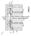
- FIG. 1 is a cross-sectional schematic view of a pressure-sensing module according to an embodiment of the present invention
- FIG. 2 is a cross-sectional schematic view of a portion of the module illustrated in FIG. 1 ;
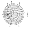
- FIG. 3 is a top schematic view along line A-A illustrated in FIG. 1 of an apparatus according to an embodiment of the present invention.
- An embodiment of the invention has full differential-pressure and gauge-pressure capability without exposing sensor elements to process fluid.
- a pressure-sensing module 10 includes a header housing 20 including a first (high-pressure) port 30 and a second (low-pressure) port 40.
- the first port 30 is configured to be in fluid communication with a first fluid-flow circuit, such as that associated with the aforementioned process fluid, having a variable or static pressure P1.
- the second port 40 is configured to be in fluid communication with a second fluid-flow circuit, which may be the ambient, having a variable or static pressure P2.
- the second port 40 may be achieved by glassing a tube in the housing 20.
- the module 10 further includes a first support member 50 and a second support member 60, each of which has a respective flexible clamping portion 70, 80, and the combination of which define at least one sealed chamber 25.
- a flexible diaphragm 90 is disposed between the first and second support members 50, 60.
- a unitary support structure (not shown) may be substituted, while retaining full functionality, for the first and second support members 50, 60. As illustrated in FIG. 1 , the diaphragm 90 is thus in fluid communication on its top side with the pressure P1 and on its bottom side with the pressure P2.
- the diaphragm 90 includes one or more sensing flexures 100 positioned on the periphery of the diaphragm 90.
- Wire bond pads 110 are provided in at least one of the flexure regions 100.
- a strain-gauge including one or more piezoelectric resistance-bridge sensing elements 140, 150 that may be built on a silicon On insulator structure.
- FIG. 3 illustrates the presence of strain-gauge elements on only one flexure 100 of the diaphragm 90, embodiments of the invention may include multiple such strain gauges on multiple ones of the flexures 100. As best illustrated in FIG.
- legs of the bridge elements are positioned so that the "+" legs 150 are on flexure 100 areas of maximum tension, and the "-" legs 140 are on flexure areas of minimum tension.
- the clamping portions 70, 80 deform corresponding to deformation of the diaphragm 90.
- a bridge 160 or other element know in the art, and operable to sense temperature, is disposed proximate to the strain sensing elements 140, 150. The temperature bridge 160 provides reliable digital pressure compensation over an extended temperature range.
- the diaphragm 90 may include one or more perforations 120 to allow access to header pins 130.
- These header pins 130 may be wire bonded to the pads 110 in the flexure area.
- the pins 130 may provide external connection to the sensing elements via, for example, a wire 170.
- pressure P1 and/or P2 is applied to the sensing diaphragm 90, which will deflect proportionally to such pressure.
- the sensing diaphragm 90 deflects, the flexures 100 allow strain to propagate to the sensing elements 140 150, which, in turn, generate at least one electrical signal proportional to the magnitude of the sensed differential and/or gauge pressure.
- the SOI substrate allows high temperature operation (e . g ., >250C) by eliminating the parasitic diodes associated with bulk structures.
- silicon to silicon joints are achieved by making one or more thermal electric bonds 180 between a layer of pyrex and silicon.
- Alternative joining technologies may be brazing or silicon-diffusion bonding.
- the sealed chamber 25 containing the sensing elements 140, 150 would be held at a vacuum or backfilled with inert gas.
- Integral stress-isolation member is built into the structure eliminating the need for a stress isolation member external to the die.
- transducer circuitry could be included to allow ultra miniature transducer functionality.
- a manufacturing process is as follows: an embodiment is produced using three silicon layers.
- the diaphragm 90 and the flexures 100 are established by the middle layer.
- the bottom layer provides access to the header pins 130, provides stress isolation, and TE bonding to the header 20.
- the top layer may be a lid, which provides the isolation from the process fluid. Both the top and bottom layers provide continuous flexures that are substantially normal to the sensing diaphragm surface 90.
- the middle layer may be fabricated first.
- the sensing elements 140, 150 are created, then the flexure 100 is thinned and the open channels 120 created.
- the bottom layer may be next, which is fabricated by etching and polishing.
- the TE bond to the middle layer is then made.
- the resulting die is then masked, and the final geometry of the bottom layer flexure is etched.
- the wafer is then sawed into individual die. Each good die is TE Bonded into the mating header.
- the top layer may be made last, with its features also formed by etching. The top layer is then sawed into individual die. The top structure is TE bonded into place last, creating the vacuum or inert atmosphere for the sensing elements 140, 150.
Landscapes
- Physics & Mathematics (AREA)
- General Physics & Mathematics (AREA)
- Chemical & Material Sciences (AREA)
- Analytical Chemistry (AREA)
- Measuring Fluid Pressure (AREA)
Abstract
Description
- When sensing pressure in aerospace or other commercial systems, it is often necessary to isolate the process fluid (e.g., fuel) from the electronic sensing elements on the pressure sensor. The usual practice for doing so consists of employing a thin metal barrier that covers a cavity that houses the pressure sensor electronic sensing elements. This cavity is then filled will inert oil and sealed, providing a means to couple the process-fluid pressure to the sensor, but at the same time isolating the sensor from the process fluid itself.
- Process fluids can be chemically destructive to the sensing element or be conductive, which provides unwanted current leakage in the sensor elements. The described isolators introduce non-correctable errors that increase approximately to the diameter ratio to the third power as the diameter of the isolator is decreased. Additionally, the oil fill has limitations with temperature swing; most oil fills that work at higher temperatures are gels at cold temperatures. In addition, the oil fill presents an additional failure mechanism; if the oil leaks out of the sensor, the sensor can no longer measure pressure and fails.
- In an embodiment, a sensing apparatus for determining the pressure of a fluid includes first and second support members. The first and second support members are configured to define at least one sealed chamber. A flexible diaphragm is disposed between the first and second support members. The diaphragm includes first and second opposing surfaces. The first opposing surface is in fluid communication with a first fluid-flow circuit, and the second opposing surface is in fluid communication with a second fluid-flow circuit. A first electronic circuit is disposed within the at least one chamber and coupled to the diaphragm for sensing a first differential pressure associated with the first and second flow circuits. The first electronic circuit is configured to produce at least one electrical signal proportional to a magnitude of the first differential pressure.
- Preferred and alternative embodiments of the present invention are described in detail below with reference to the following drawings.
-
FIG. 1 is a cross-sectional schematic view of a pressure-sensing module according to an embodiment of the present invention; -
FIG. 2 is a cross-sectional schematic view of a portion of the module illustrated inFIG. 1 ; and -
FIG. 3 is a top schematic view along line A-A illustrated inFIG. 1 of an apparatus according to an embodiment of the present invention. - An embodiment of the invention has full differential-pressure and gauge-pressure capability without exposing sensor elements to process fluid.
- Referring to
FIG. 1 , a pressure-sensing module 10 includes aheader housing 20 including a first (high-pressure)port 30 and a second (low-pressure)port 40. Thefirst port 30 is configured to be in fluid communication with a first fluid-flow circuit, such as that associated with the aforementioned process fluid, having a variable or static pressure P1. Thesecond port 40 is configured to be in fluid communication with a second fluid-flow circuit, which may be the ambient, having a variable or static pressure P2. Thesecond port 40 may be achieved by glassing a tube in thehousing 20. - The
module 10 further includes afirst support member 50 and asecond support member 60, each of which has a respectiveflexible clamping portion chamber 25. Aflexible diaphragm 90 is disposed between the first andsecond support members second support members FIG. 1 , thediaphragm 90 is thus in fluid communication on its top side with the pressure P1 and on its bottom side with the pressure P2. - As best seen in
FIG. 3 , thediaphragm 90 includes one or moresensing flexures 100 positioned on the periphery of thediaphragm 90.Wire bond pads 110 are provided in at least one of theflexure regions 100. Connected to thepads 110, in an embodiment, is a strain-gauge including one or more piezoelectric resistance-bridge sensing elements FIG. 3 illustrates the presence of strain-gauge elements on only oneflexure 100 of thediaphragm 90, embodiments of the invention may include multiple such strain gauges on multiple ones of theflexures 100. As best illustrated inFIG. 2 , and in an embodiment, legs of the bridge elements are positioned so that the "+"legs 150 are onflexure 100 areas of maximum tension, and the "-"legs 140 are on flexure areas of minimum tension. Note that theclamping portions diaphragm 90. In an embodiment, and as illustrated inFIG. 3 , abridge 160 or other element know in the art, and operable to sense temperature, is disposed proximate to thestrain sensing elements temperature bridge 160 provides reliable digital pressure compensation over an extended temperature range. - The
diaphragm 90 may include one ormore perforations 120 to allow access toheader pins 130. Theseheader pins 130 may be wire bonded to thepads 110 in the flexure area. Thepins 130 may provide external connection to the sensing elements via, for example, awire 170. - In an embodiment, pressure P1 and/or P2 is applied to the
sensing diaphragm 90, which will deflect proportionally to such pressure. As thesensing diaphragm 90 deflects, theflexures 100 allow strain to propagate to thesensing elements 140 150, which, in turn, generate at least one electrical signal proportional to the magnitude of the sensed differential and/or gauge pressure. - The SOI substrate allows high temperature operation (e.g., >250C) by eliminating the parasitic diodes associated with bulk structures. In a preferred embodiment, silicon to silicon joints are achieved by making one or more thermal
electric bonds 180 between a layer of pyrex and silicon. Alternative joining technologies may be brazing or silicon-diffusion bonding. - In a preferred embodiment, the sealed
chamber 25 containing thesensing elements - Features of one or more embodiments include:
- - Capability of measuring pressures up to 2000 psi.
- - Capability of pressure measurements at a temperature of up to 275C.
- - Provides high sensitivities of -5%
- - Integral stress-isolation member is built into the structure eliminating the need for a stress isolation member external to the die.
- - Environmentally protected areas are available near the
sensing elements - -Sensors built with this construction are inherently small in size, limited only by the die and header sizes.
- - Small sizes also allow minimal weight; ideal for size and weight sensitive applications like aerospace.
- - The lack of oil fill makes these sensors advantageous for differential-pressure applications where one leg operates near vacuum. Oil fills can outgas under these conditions, causing large measurement errors.
- - Absolute pressure silicon structures have been shown to provide excellent accuracy and stability when properly stress isolated.
- A manufacturing process according to an embodiment is as follows: an embodiment is produced using three silicon layers. The
diaphragm 90 and theflexures 100 are established by the middle layer. The bottom layer provides access to theheader pins 130, provides stress isolation, and TE bonding to theheader 20. The top layer may be a lid, which provides the isolation from the process fluid. Both the top and bottom layers provide continuous flexures that are substantially normal to thesensing diaphragm surface 90. - The middle layer may be fabricated first. The
sensing elements flexure 100 is thinned and theopen channels 120 created. - The bottom layer may be next, which is fabricated by etching and polishing. The TE bond to the middle layer is then made. The resulting die is then masked, and the final geometry of the bottom layer flexure is etched. The wafer is then sawed into individual die. Each good die is TE Bonded into the mating header.
- The top layer may be made last, with its features also formed by etching. The top layer is then sawed into individual die. The top structure is TE bonded into place last, creating the vacuum or inert atmosphere for the
sensing elements - While a preferred embodiment of the invention has been illustrated and described, as noted above, many changes can be made without departing from the spirit and scope of the invention. Accordingly, the scope of the invention is not limited by the disclosure of the preferred embodiment. Instead, the invention should be determined entirely by reference to the claims that follow.
The embodiments of the invention in which an exclusive property or privilege is claimed are defined as follows:
Claims (7)
- A pressure-sensing module (10), comprising:a housing (20) including first and second ports (30, 40) configured to be respectively coupled to first and second fluid-flow circuits;first and second support members (50, 60) disposed within the housing, the first and second support members configured to define at least one sealed chamber (25);a flexible diaphragm (90) disposed between the first and second support members, the diaphragm including first and second opposing surfaces, the first opposing surface being in fluid communication with the first fluid-flow circuit, and the second opposing surface being in fluid communication with the second fluid-flow circuit; andan electronic circuit (140, 150) disposed within the at least one chamber and coupled to the diaphragm for sensing a differential pressure associated with the first and second flow circuits, the electronic circuit configured to produce at least one electrical signal proportional to a magnitude of the differential pressure.
- The module of claim 1 wherein the first and second support members include respective flexible clamping portions (70, 80) configured to clamp the diaphragm between the first and second support members.
- The module of claim 1 wherein the electronic circuit is further configured to produce at least one electrical signal proportional to a magnitude of the gauge pressure associated with at least one of the first and second flow circuits.
- The module of claim 1 wherein the first and second support members are annular in configuration.
- The module of claim 1 wherein the electronic circuit comprises at least one resistance strain gauge.
- The module of claim 1 wherein the electronic circuit comprises at least one temperature sensor (160).
- The module of claim 1 wherein the at least one chamber is held at a vacuum state.
Applications Claiming Priority (1)
| Application Number | Priority Date | Filing Date | Title |
|---|---|---|---|
| US12/127,641 US7698951B2 (en) | 2008-05-27 | 2008-05-27 | Pressure-sensor apparatus |
Publications (2)
| Publication Number | Publication Date |
|---|---|
| EP2128583A2 true EP2128583A2 (en) | 2009-12-02 |
| EP2128583A3 EP2128583A3 (en) | 2012-11-07 |
Family
ID=40999956
Family Applications (1)
| Application Number | Title | Priority Date | Filing Date |
|---|---|---|---|
| EP09160879A Withdrawn EP2128583A3 (en) | 2008-05-27 | 2009-05-21 | Pressure-sensor apparatus |
Country Status (2)
| Country | Link |
|---|---|
| US (1) | US7698951B2 (en) |
| EP (1) | EP2128583A3 (en) |
Cited By (3)
| Publication number | Priority date | Publication date | Assignee | Title |
|---|---|---|---|---|
| WO2013048598A1 (en) * | 2011-09-26 | 2013-04-04 | Rosemount, Inc. | Process fluid pressure transmitter with separated sensor and sensor electronics |
| CN106124117A (en) * | 2016-06-14 | 2016-11-16 | 中国科学院地质与地球物理研究所 | A kind of double cavity pressure meter chip and manufacturing process thereof |
| CN112798158A (en) * | 2021-04-14 | 2021-05-14 | 江西新力传感科技有限公司 | Pressure sensor chip and pressure sensor |
Families Citing this family (6)
| Publication number | Priority date | Publication date | Assignee | Title |
|---|---|---|---|---|
| US8065917B1 (en) | 2010-05-18 | 2011-11-29 | Honeywell International Inc. | Modular pressure sensor |
| US9261419B2 (en) | 2014-01-23 | 2016-02-16 | Honeywell International Inc. | Modular load structure assembly having internal strain gaged sensing |
| US9593995B2 (en) * | 2014-02-28 | 2017-03-14 | Measurement Specialties, Inc. | Package for a differential pressure sensing die |
| US10132706B2 (en) * | 2015-09-28 | 2018-11-20 | Apple Inc. | Waterproof barometric sensor in an electronic device |
| US10466047B2 (en) * | 2015-09-30 | 2019-11-05 | Apple Inc. | Barometric sensor integration in a water resistant electronic device |
| CN209326840U (en) | 2018-12-27 | 2019-08-30 | 热敏碟公司 | Pressure sensor and pressure transmitter |
Family Cites Families (11)
| Publication number | Priority date | Publication date | Assignee | Title |
|---|---|---|---|---|
| US3296868A (en) * | 1963-07-22 | 1967-01-10 | Bailey Meter Co | Differential pressure transmitter |
| US3427884A (en) * | 1966-12-23 | 1969-02-18 | Whittaker Corp | Differential pressure transducer |
| US3427885A (en) * | 1966-12-23 | 1969-02-18 | Whittaker Corp | Differential pressure transducer |
| US3712143A (en) * | 1971-12-21 | 1973-01-23 | Honeywell Inc | Differential pressure responsive apparatus |
| US4176557A (en) * | 1976-06-07 | 1979-12-04 | Bunker Ramo Corporation | Pressure sensor |
| US4928376A (en) * | 1989-07-31 | 1990-05-29 | Motorola Inc. | Method for filling a cavity, such as a sensor cavity, with an incompressible fluid |
| US5693887A (en) * | 1995-10-03 | 1997-12-02 | Nt International, Inc. | Pressure sensor module having non-contaminating body and isolation member |
| FR2775075B1 (en) * | 1998-02-18 | 2000-05-05 | Theobald Sa A | DIFFERENTIAL PRESSURE SENSOR |
| US5999082A (en) * | 1998-03-25 | 1999-12-07 | Kulite Semiconductor Products, Inc. | Compensated oil-filled pressure transducers |
| US6789429B2 (en) * | 1999-08-06 | 2004-09-14 | Setra System, Inc. | Capacitive pressure sensor having encapsulated resonating components |
| US6272928B1 (en) * | 2000-01-24 | 2001-08-14 | Kulite Semiconductor Products | Hermetically sealed absolute and differential pressure transducer |
-
2008
- 2008-05-27 US US12/127,641 patent/US7698951B2/en active Active
-
2009
- 2009-05-21 EP EP09160879A patent/EP2128583A3/en not_active Withdrawn
Cited By (4)
| Publication number | Priority date | Publication date | Assignee | Title |
|---|---|---|---|---|
| WO2013048598A1 (en) * | 2011-09-26 | 2013-04-04 | Rosemount, Inc. | Process fluid pressure transmitter with separated sensor and sensor electronics |
| CN106124117A (en) * | 2016-06-14 | 2016-11-16 | 中国科学院地质与地球物理研究所 | A kind of double cavity pressure meter chip and manufacturing process thereof |
| CN106124117B (en) * | 2016-06-14 | 2019-04-23 | 中国科学院地质与地球物理研究所 | A dual cavity pressure gauge chip and its manufacturing process |
| CN112798158A (en) * | 2021-04-14 | 2021-05-14 | 江西新力传感科技有限公司 | Pressure sensor chip and pressure sensor |
Also Published As
| Publication number | Publication date |
|---|---|
| US7698951B2 (en) | 2010-04-20 |
| US20090293628A1 (en) | 2009-12-03 |
| EP2128583A3 (en) | 2012-11-07 |
Similar Documents
| Publication | Publication Date | Title |
|---|---|---|
| US7698951B2 (en) | Pressure-sensor apparatus | |
| EP2189773B1 (en) | Design of wet/wet differential pressure sensor based on microelectronic packaging process | |
| US7610812B2 (en) | High accuracy, high temperature, redundant media protected differential transducers | |
| US8297125B2 (en) | Media isolated differential pressure sensor with cap | |
| US5483834A (en) | Suspended diaphragm pressure sensor | |
| CN107782485B (en) | Differential pressure sensor integrated with common mode error compensation | |
| JP3207123U (en) | Media isolation pressure sensor | |
| CN103477199B (en) | The differential pressure pickup of withstand voltage encapsulation | |
| US7436037B2 (en) | Moisture resistant pressure sensors | |
| US6612179B1 (en) | Method and apparatus for the determination of absolute pressure and differential pressure therefrom | |
| US7866215B2 (en) | Redundant self compensating leadless pressure sensor | |
| WO2003012386A1 (en) | Pressure sensor | |
| JPH01141328A (en) | differential pressure transmitter | |
| US7597005B2 (en) | Pressure sensor housing and configuration | |
| EP0405633B1 (en) | Pressure/Differential measuring device | |
| US8183975B2 (en) | Miniature pressure transducer | |
| US11359985B2 (en) | Oil filled transducers with isolated compensating capsule | |
| US11692895B2 (en) | Differential pressure sensor | |
| JPH10142086A (en) | Semiconductor pressure sensor, method of manufacturing the same, and differential pressure transmitter using the same | |
| CN118089999B (en) | Pressure sensor, pressure sensing device and electronic device | |
| JPH04267566A (en) | Semiconductor pressure sensor for high pressure | |
| JPH04302479A (en) | Semiconductor pressure sensor |
Legal Events
| Date | Code | Title | Description |
|---|---|---|---|
| PUAI | Public reference made under article 153(3) epc to a published international application that has entered the european phase |
Free format text: ORIGINAL CODE: 0009012 |
|
| 17P | Request for examination filed |
Effective date: 20090521 |
|
| AK | Designated contracting states |
Kind code of ref document: A2 Designated state(s): AT BE BG CH CY CZ DE DK EE ES FI FR GB GR HR HU IE IS IT LI LT LU LV MC MK MT NL NO PL PT RO SE SI SK TR |
|
| PUAL | Search report despatched |
Free format text: ORIGINAL CODE: 0009013 |
|
| AK | Designated contracting states |
Kind code of ref document: A3 Designated state(s): AT BE BG CH CY CZ DE DK EE ES FI FR GB GR HR HU IE IS IT LI LT LU LV MC MK MT NL NO PL PT RO SE SI SK TR |
|
| AX | Request for extension of the european patent |
Extension state: AL BA RS |
|
| RIC1 | Information provided on ipc code assigned before grant |
Ipc: G01L 19/00 20060101ALI20120928BHEP Ipc: G01L 9/00 20060101ALI20120928BHEP Ipc: G01L 9/06 20060101AFI20120928BHEP |
|
| 17Q | First examination report despatched |
Effective date: 20121030 |
|
| STAA | Information on the status of an ep patent application or granted ep patent |
Free format text: STATUS: THE APPLICATION IS DEEMED TO BE WITHDRAWN |
|
| 18D | Application deemed to be withdrawn |
Effective date: 20130310 |