EP3128281B1 - Flexible seal for missile container - Google Patents
Flexible seal for missile container Download PDFInfo
- Publication number
- EP3128281B1 EP3128281B1 EP16290139.1A EP16290139A EP3128281B1 EP 3128281 B1 EP3128281 B1 EP 3128281B1 EP 16290139 A EP16290139 A EP 16290139A EP 3128281 B1 EP3128281 B1 EP 3128281B1
- Authority
- EP
- European Patent Office
- Prior art keywords
- flexible seal
- missile
- container
- composite
- flexible
- Prior art date
- Legal status (The legal status is an assumption and is not a legal conclusion. Google has not performed a legal analysis and makes no representation as to the accuracy of the status listed.)
- Active
Links
- 239000002131 composite material Substances 0.000 claims description 60
- 239000002184 metal Substances 0.000 claims description 33
- 229920001971 elastomer Polymers 0.000 claims description 26
- 239000000806 elastomer Substances 0.000 claims description 26
- 239000004744 fabric Substances 0.000 claims description 17
- 238000004519 manufacturing process Methods 0.000 description 10
- 210000001519 tissue Anatomy 0.000 description 8
- 239000011248 coating agent Substances 0.000 description 7
- 238000000576 coating method Methods 0.000 description 7
- 239000007789 gas Substances 0.000 description 6
- 238000010304 firing Methods 0.000 description 4
- 238000007789 sealing Methods 0.000 description 3
- 239000000835 fiber Substances 0.000 description 2
- 230000007246 mechanism Effects 0.000 description 2
- 239000012528 membrane Substances 0.000 description 2
- 238000011144 upstream manufacturing Methods 0.000 description 2
- 238000004073 vulcanization Methods 0.000 description 2
- 229920000049 Carbon (fiber) Polymers 0.000 description 1
- 241001415961 Gaviidae Species 0.000 description 1
- 239000004952 Polyamide Substances 0.000 description 1
- 125000000484 butyl group Chemical group [H]C([*])([H])C([H])([H])C([H])([H])C([H])([H])[H] 0.000 description 1
- 238000003490 calendering Methods 0.000 description 1
- 239000004917 carbon fiber Substances 0.000 description 1
- 238000004891 communication Methods 0.000 description 1
- 238000005520 cutting process Methods 0.000 description 1
- 238000000151 deposition Methods 0.000 description 1
- 238000009826 distribution Methods 0.000 description 1
- 239000003365 glass fiber Substances 0.000 description 1
- 239000011261 inert gas Substances 0.000 description 1
- 239000000463 material Substances 0.000 description 1
- 239000007769 metal material Substances 0.000 description 1
- 238000000465 moulding Methods 0.000 description 1
- 229920001084 poly(chloroprene) Polymers 0.000 description 1
- 229920002647 polyamide Polymers 0.000 description 1
- 229920000728 polyester Polymers 0.000 description 1
- 229920001296 polysiloxane Polymers 0.000 description 1
- 239000003380 propellant Substances 0.000 description 1
- 229910001220 stainless steel Inorganic materials 0.000 description 1
- 239000010935 stainless steel Substances 0.000 description 1
- 239000004753 textile Substances 0.000 description 1
Images

Classifications
-
- F—MECHANICAL ENGINEERING; LIGHTING; HEATING; WEAPONS; BLASTING
- F41—WEAPONS
- F41F—APPARATUS FOR LAUNCHING PROJECTILES OR MISSILES FROM BARRELS, e.g. CANNONS; LAUNCHERS FOR ROCKETS OR TORPEDOES; HARPOON GUNS
- F41F3/00—Rocket or torpedo launchers
- F41F3/04—Rocket or torpedo launchers for rockets
- F41F3/077—Doors or covers for launching tubes
-
- B—PERFORMING OPERATIONS; TRANSPORTING
- B32—LAYERED PRODUCTS
- B32B—LAYERED PRODUCTS, i.e. PRODUCTS BUILT-UP OF STRATA OF FLAT OR NON-FLAT, e.g. CELLULAR OR HONEYCOMB, FORM
- B32B15/00—Layered products comprising a layer of metal
- B32B15/04—Layered products comprising a layer of metal comprising metal as the main or only constituent of a layer, which is next to another layer of the same or of a different material
- B32B15/043—Layered products comprising a layer of metal comprising metal as the main or only constituent of a layer, which is next to another layer of the same or of a different material of metal
-
- B—PERFORMING OPERATIONS; TRANSPORTING
- B32—LAYERED PRODUCTS
- B32B—LAYERED PRODUCTS, i.e. PRODUCTS BUILT-UP OF STRATA OF FLAT OR NON-FLAT, e.g. CELLULAR OR HONEYCOMB, FORM
- B32B15/00—Layered products comprising a layer of metal
- B32B15/14—Layered products comprising a layer of metal next to a fibrous or filamentary layer
-
- B—PERFORMING OPERATIONS; TRANSPORTING
- B32—LAYERED PRODUCTS
- B32B—LAYERED PRODUCTS, i.e. PRODUCTS BUILT-UP OF STRATA OF FLAT OR NON-FLAT, e.g. CELLULAR OR HONEYCOMB, FORM
- B32B25/00—Layered products comprising a layer of natural or synthetic rubber
- B32B25/02—Layered products comprising a layer of natural or synthetic rubber with fibres or particles being present as additives in the layer
-
- F—MECHANICAL ENGINEERING; LIGHTING; HEATING; WEAPONS; BLASTING
- F16—ENGINEERING ELEMENTS AND UNITS; GENERAL MEASURES FOR PRODUCING AND MAINTAINING EFFECTIVE FUNCTIONING OF MACHINES OR INSTALLATIONS; THERMAL INSULATION IN GENERAL
- F16J—PISTONS; CYLINDERS; SEALINGS
- F16J15/00—Sealings
- F16J15/02—Sealings between relatively-stationary surfaces
- F16J15/06—Sealings between relatively-stationary surfaces with solid packing compressed between sealing surfaces
- F16J15/064—Sealings between relatively-stationary surfaces with solid packing compressed between sealing surfaces the packing combining the sealing function with other functions
-
- F—MECHANICAL ENGINEERING; LIGHTING; HEATING; WEAPONS; BLASTING
- F16—ENGINEERING ELEMENTS AND UNITS; GENERAL MEASURES FOR PRODUCING AND MAINTAINING EFFECTIVE FUNCTIONING OF MACHINES OR INSTALLATIONS; THERMAL INSULATION IN GENERAL
- F16J—PISTONS; CYLINDERS; SEALINGS
- F16J15/00—Sealings
- F16J15/02—Sealings between relatively-stationary surfaces
- F16J15/06—Sealings between relatively-stationary surfaces with solid packing compressed between sealing surfaces
- F16J15/067—Split packings
-
- F—MECHANICAL ENGINEERING; LIGHTING; HEATING; WEAPONS; BLASTING
- F16—ENGINEERING ELEMENTS AND UNITS; GENERAL MEASURES FOR PRODUCING AND MAINTAINING EFFECTIVE FUNCTIONING OF MACHINES OR INSTALLATIONS; THERMAL INSULATION IN GENERAL
- F16J—PISTONS; CYLINDERS; SEALINGS
- F16J15/00—Sealings
- F16J15/02—Sealings between relatively-stationary surfaces
- F16J15/06—Sealings between relatively-stationary surfaces with solid packing compressed between sealing surfaces
- F16J15/10—Sealings between relatively-stationary surfaces with solid packing compressed between sealing surfaces with non-metallic packing
- F16J15/12—Sealings between relatively-stationary surfaces with solid packing compressed between sealing surfaces with non-metallic packing with metal reinforcement or covering
- F16J15/121—Sealings between relatively-stationary surfaces with solid packing compressed between sealing surfaces with non-metallic packing with metal reinforcement or covering with metal reinforcement
- F16J15/122—Sealings between relatively-stationary surfaces with solid packing compressed between sealing surfaces with non-metallic packing with metal reinforcement or covering with metal reinforcement generally parallel to the surfaces
-
- B—PERFORMING OPERATIONS; TRANSPORTING
- B32—LAYERED PRODUCTS
- B32B—LAYERED PRODUCTS, i.e. PRODUCTS BUILT-UP OF STRATA OF FLAT OR NON-FLAT, e.g. CELLULAR OR HONEYCOMB, FORM
- B32B2250/00—Layers arrangement
- B32B2250/40—Symmetrical or sandwich layers, e.g. ABA, ABCBA, ABCCBA
-
- B—PERFORMING OPERATIONS; TRANSPORTING
- B32—LAYERED PRODUCTS
- B32B—LAYERED PRODUCTS, i.e. PRODUCTS BUILT-UP OF STRATA OF FLAT OR NON-FLAT, e.g. CELLULAR OR HONEYCOMB, FORM
- B32B2260/00—Layered product comprising an impregnated, embedded, or bonded layer wherein the layer comprises an impregnation, embedding, or binder material
- B32B2260/02—Composition of the impregnated, bonded or embedded layer
- B32B2260/021—Fibrous or filamentary layer
- B32B2260/023—Two or more layers
-
- B—PERFORMING OPERATIONS; TRANSPORTING
- B32—LAYERED PRODUCTS
- B32B—LAYERED PRODUCTS, i.e. PRODUCTS BUILT-UP OF STRATA OF FLAT OR NON-FLAT, e.g. CELLULAR OR HONEYCOMB, FORM
- B32B2260/00—Layered product comprising an impregnated, embedded, or bonded layer wherein the layer comprises an impregnation, embedding, or binder material
- B32B2260/04—Impregnation, embedding, or binder material
- B32B2260/048—Natural or synthetic rubber
-
- B—PERFORMING OPERATIONS; TRANSPORTING
- B32—LAYERED PRODUCTS
- B32B—LAYERED PRODUCTS, i.e. PRODUCTS BUILT-UP OF STRATA OF FLAT OR NON-FLAT, e.g. CELLULAR OR HONEYCOMB, FORM
- B32B2262/00—Composition or structural features of fibres which form a fibrous or filamentary layer or are present as additives
- B32B2262/02—Synthetic macromolecular fibres
-
- B—PERFORMING OPERATIONS; TRANSPORTING
- B32—LAYERED PRODUCTS
- B32B—LAYERED PRODUCTS, i.e. PRODUCTS BUILT-UP OF STRATA OF FLAT OR NON-FLAT, e.g. CELLULAR OR HONEYCOMB, FORM
- B32B2262/00—Composition or structural features of fibres which form a fibrous or filamentary layer or are present as additives
- B32B2262/10—Inorganic fibres
-
- B—PERFORMING OPERATIONS; TRANSPORTING
- B32—LAYERED PRODUCTS
- B32B—LAYERED PRODUCTS, i.e. PRODUCTS BUILT-UP OF STRATA OF FLAT OR NON-FLAT, e.g. CELLULAR OR HONEYCOMB, FORM
- B32B2307/00—Properties of the layers or laminate
- B32B2307/50—Properties of the layers or laminate having particular mechanical properties
- B32B2307/51—Elastic
-
- B—PERFORMING OPERATIONS; TRANSPORTING
- B32—LAYERED PRODUCTS
- B32B—LAYERED PRODUCTS, i.e. PRODUCTS BUILT-UP OF STRATA OF FLAT OR NON-FLAT, e.g. CELLULAR OR HONEYCOMB, FORM
- B32B2307/00—Properties of the layers or laminate
- B32B2307/70—Other properties
- B32B2307/724—Permeability to gases, adsorption
- B32B2307/7242—Non-permeable
-
- B—PERFORMING OPERATIONS; TRANSPORTING
- B32—LAYERED PRODUCTS
- B32B—LAYERED PRODUCTS, i.e. PRODUCTS BUILT-UP OF STRATA OF FLAT OR NON-FLAT, e.g. CELLULAR OR HONEYCOMB, FORM
- B32B2319/00—Synthetic rubber
-
- B—PERFORMING OPERATIONS; TRANSPORTING
- B32—LAYERED PRODUCTS
- B32B—LAYERED PRODUCTS, i.e. PRODUCTS BUILT-UP OF STRATA OF FLAT OR NON-FLAT, e.g. CELLULAR OR HONEYCOMB, FORM
- B32B2435/00—Closures, end caps, stoppers
- B32B2435/02—Closures, end caps, stoppers for containers
-
- B—PERFORMING OPERATIONS; TRANSPORTING
- B32—LAYERED PRODUCTS
- B32B—LAYERED PRODUCTS, i.e. PRODUCTS BUILT-UP OF STRATA OF FLAT OR NON-FLAT, e.g. CELLULAR OR HONEYCOMB, FORM
- B32B2581/00—Seals; Sealing equipment; Gaskets
Definitions
- the present invention relates to a flexible seal for a missile container.
- a container seal has the function of sealing the container to protect a missile installed in this container.
- the operculum must be able to open in order to let the missile or the propulsion gases pass when the latter fires.
- a seal of the deformable type intended to equip the bottom of a missile container and able to open under the thrust of the propulsion gases of a missile contained in the container and to close after ejection of the missile.
- the lid comprises a grid and a stack of elastic blades sandwiched between a thermal protection membrane and a sealing membrane, upstream and downstream, and held between an upstream support frame and a downstream support frame.
- the present invention aims to overcome at least some of the aforementioned drawbacks. More specifically, it aims to remedy the problem of debris presenting a hazard for equipment, while ensuring a moderate effort on the radome of the missile, a low mass and a reduced manufacturing cost.
- the present invention relates to a flexible cover, intended to be mounted on a missile container and able to open under a thrust.
- At least the composite layer and the metal blade are configured to return to an initial position after an opening of the lid.
- the fabric or fabrics that are introduced into the elastomer to form the composite material ensure the mechanical strength of the flexible seal which is, moreover, sealed thanks in particular to the elastomer.
- the metal blade which is inserted into the elastomer of the composite material makes it possible to direct a precise cutting of said composite material (elastomer / fabric) along the pre-cut lines, which allows an easier opening.
- the layer composite and the metal blade, thus formed allow the flexible cover to return to an initial position after an opening.
- a flexible seal is thus obtained which makes it possible to avoid the generation of debris (presenting a danger for the equipment), while guaranteeing a moderate effort on the missile radome, a low mass and a reduced manufacturing cost.
- the precut lines are arranged radially relative to the center of the lid.
- said at least one composite layer and the metal blade are arranged so that at least some of the pre-cut lines of the metal blade are parallel to at least one yarn orientation of the composite material fabric. (of the composite layer).
- the metal blade is a single piece, in which said precut lines are made.
- the metal blade also has recesses to allow to receive a portion of the elastomer of said at least one composite layer.
- the present invention also relates to a missile container, which comprises at least one flexible cap as described above.
- the present invention further relates to a weapon system that includes at least one such missile container.
- the figure 1 is a schematic cross section of a preferred embodiment of a flexible cap according to the invention.
- the figure 2 a schematic cross section of another embodiment of a flexible cap according to the invention.
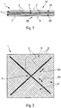
- FIGS. 3 and 4 are two schematic plan views, illustrating different embodiments of pre-cut lines of a metal blade of a flexible cover.
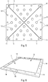
- the figure 5 is a plan view of a preferred embodiment of a metal blade of a flexible cover.
- the figure 6 is a schematic view, in perspective, of fixing means of a flexible cover.
- the flexible seal 1 illustrating the invention and shown schematically on the figure 1 is intended to be mounted on a missile container (not shown).
- This missile container is part of a weapon system (also not shown).
- the flexible lid 1 has the function of sealing the container to protect a missile installed in the container.
- the flexible cover must be able to open in order to let the missile or the propulsion gases pass during a firing of the latter.
- the flexible seal 1 is configured to open under a thrust.
- this thrust can be generated during a firing by a contact of the flexible cover by the missile or by an internal overpressure generated by dedicated means or propulsion gases of the missile.
- composite layer 2 and the metal blade 4 are configured to return to an initial position after an opening of the flexible lid 1.
- the metal blade 4 which is inserted into the elastomer 3 of the composite material 7 makes it possible to direct a precise cut of the composite material (elastomer / fabric) along the pre-cut lines 5 of embrittlement.
- tissue (s) 16 ( Figures 3 and 4 ) which are inserted into the elastomer 3 to form the composite material 7 ensure the mechanical strength of the flexible seal 1.
- This or these tissues are made, in in particular, based on carbon fibers or glass fibers, or on textile fibers (polyester, polyamide, etc.).
- the composite material 7 also makes it possible, thanks to the elastomer 3, to make the flexible seal 1 hermetic.
- the elastomer 3 can be made of different materials.
- this elastomer is of butyl, neoprene, silicone, ...
- the flexible cover 1 is sized to allow the re-closing of the petals 6 after a shot.
- the flexible seal 1 comprises two composite layers 2 which are arranged on either side of the metal blade 4, on the faces 4A and 4B of the latter.
- a single composite layer 2 (fabric / elastomer) is provided on the outer face 4A of the metal blade 4, that is to say on the face 1A which will be directed towards the outside of the container in the mounted position of the flexible cover 1. This makes it possible to limit the efforts required for opening.
- the flexible seal 1 further comprises an anti-friction coating 8 on the inner face 1B, which is therefore intended to be placed towards the inside of the container.
- This anti-friction coating 8 makes it possible in particular to limit the friction during the passage of the missile through the flexible cover 1.
- the antifriction coating 8 is made for example from a metal material, which allows, in addition to reducing the coefficient of friction, to provide electrical continuity.
- the metal blade 4 is thus split ( Figures 1 to 4 ), which facilitates the tearing of the composite material 7 (fabric / elastomer) of the composite layer 2 in precise directions.
- the pre-cut lines 5 are arranged radially with respect to the center 9 of the flexible cap 1, as shown in FIGS. Figures 3 and 4 .
- the composite layer (s) 2 and the metal strip 4 are arranged such that at least some of the pre-cut lines 5 of the metal strip 4 are adapted to at least one orientation D1, D2 of at least some of the threads (or fibers) 10 of the fabric 16 of the composite material 7 of the composite layer 2. More precisely, the precut lines 5 are parallel to the orientations D1 and D2 of the threads 10 of the fabric 16.
- the pre-cut lines 5 (or slots) of the metal blade 4 are more or less numerous, for example two lines oriented along the diagonals as in the example of FIG. figure 3 or four lines oriented along the diagonals and the mediators of the sides as shown on the figure 4 .
- the metal blade 4 is a single piece, in which are formed the precut lines 5 to ensure the tear (according to the diagonals for example).
- the ends of the precut lines 5 are each provided with a round hole 11.
- the metal blade 4 comprises, as represented on the figure 5 , additional recesses 12, of all possible shapes, in particular round, to allow to receive a portion of the elastomer of the composite layer or 2. This ensures a good distribution of the elastomer and good fixing.
- the metal blade 4 also includes openings (or holes) 13 for the passage of clamping screws.
- elements 14 for example stainless steel, in particular four square-shaped elements 14, as shown in the example of FIG. figure 6 , allow to clamp the flexible cover 1 on the container (not shown) with screws passing through holes 15.
- the flexible seal 1 is preferably designed to hold pressures between 1 and 5 bar, and to open from 5 bar.
- the operation of the flexible lid 1 is also specified.
- the flexible seal 1 and more particularly the composite layer (s) 2 and, where appropriate, also the anti-friction coating (8) tear in the precut lines 5, and the flexible petals 6 thus formed bend outwards to open the flexible cover 1 and release the passage for the missile.
- the flexible petals 6 return to an initial position so that the flexible cover 1 is close to its position before opening to allow the closure of the door of the cell.
- a container of a missile launcher which is embarked on a ship.
- a container generally comprises a series of cells, each cell being intended to receive a missile placed in its container.
- the upper part of a cell opens at the deck of the ship and is closed, outside the launching phases, by a door.
- the lower part of a cell has a communication opening opening into a chamber for receiving the gases emitted during the launch of a missile.
- the upper and lower parts of each container are closed in a sealed manner, by a lid provided with a high flexible lid, such as the flexible lid 1 specified above, and by a bottom provided, for example, also with a low flexible lid such as the flexible lid 1.
- the inner volume of the container is, in general, filled with an inert gas at overpressure relative to the atmosphere.
- an inert gas at overpressure relative to the atmosphere.
Description
La présente invention concerne un opercule flexible pour conteneur de missile.The present invention relates to a flexible seal for a missile container.
On sait qu'un opercule de conteneur a pour fonction de fermer hermétiquement le conteneur afin de protéger un missile installé dans ce conteneur. L'opercule doit pouvoir s'ouvrir afin de laisser passer le missile ou les gaz de propulsion lors du tir de ce dernier.It is known that a container seal has the function of sealing the container to protect a missile installed in this container. The operculum must be able to open in order to let the missile or the propulsion gases pass when the latter fires.
Généralement, les opercules se divisent en deux catégories :
- des opercules fragmentables, qui sont réalisés en général en matériaux composites ; et
- des mécanismes à ouvertures automatiques, le plus généralement métalliques.
- fragmentable opercules, which are generally made of composite materials; and
- mechanisms with automatic openings, the most generally metallic.
Ces solutions présentent différents inconvénients. Plus précisément, les inconvénients de ces solutions sont :
- pour les opercules en matériaux composites :
- la présence de débris projetés à des vitesses élevées dans diverses directions, ces débris présentant un danger pour les équipements à proximité, et même parfois pour le missile lui-même ; et
- dans certains cas, un effort important sur le radôme du missile lors de la traversée de l'opercule en phase de départ ; et
- pour les mécanismes à ouvertures automatiques :
- une gestion plus complexe de la sécurité afin de garantir l'ouverture ;
- une masse beaucoup plus importante ; et
- un coût de fabrication élevé.
- for lids made of composite materials:
- the presence of debris projected at high speeds in various directions, these debris presenting a danger for nearby equipment, and sometimes even for the missile itself; and
- in some cases, a significant effort on the radome of the missile during the crossing of the seal in the departure phase; and
- for mechanisms with automatic openings:
- more complex security management to ensure openness;
- a much larger mass; and
- a high manufacturing cost.
Par le document
La présente invention a pour objet de pallier au moins certains des inconvénients précités. Plus précisément, elle a pour objet de remédier au problème des débris présentant un danger pour les équipements, tout en garantissant un effort modéré sur le radôme du missile, une faible masse et un coût de fabrication réduit.The present invention aims to overcome at least some of the aforementioned drawbacks. More specifically, it aims to remedy the problem of debris presenting a hazard for equipment, while ensuring a moderate effort on the radome of the missile, a low mass and a reduced manufacturing cost.
La présente invention concerne un opercule flexible, destiné à être monté sur un conteneur de missile et apte à s'ouvrir sous une poussée.The present invention relates to a flexible cover, intended to be mounted on a missile container and able to open under a thrust.
Selon l'invention, l'opercule flexible comporte :
- au moins une couche dite composite, formée d'un matériau composite constitué d'au moins un tissu et d'au moins un élastomère ; et
- au moins une lame métallique plane, solidarisée de ladite couché composite par de l'élastomère et comprenant des lignes prédécoupées de fragilisation de l'opercule, les lignes prédécoupées étant agencées de manière à créer des zones en forme de pétales.
- at least one so-called composite layer, formed of a composite material consisting of at least one fabric and at least one elastomer; and
- at least one flat metal blade, secured to said composite coating by elastomer and comprising pre-cut lines of embrittlement of the lid, the precut lines being arranged to create petal-shaped areas.
Avantageusement, au moins la couche composite et la lame métallique sont configurées pour revenir vers une position initiale après une ouverture de l'opercule.Advantageously, at least the composite layer and the metal blade are configured to return to an initial position after an opening of the lid.
Ainsi, grâce à l'invention, le ou les tissus qui sont introduits dans l'élastomère pour former le matériau composite assurent la tenue mécanique de l'opercule flexible qui est, de plus, rendu hermétique grâce notamment à l'élastomère. La lame métallique qui est insérée dans l'élastomère du matériau composite permet de diriger une découpe précise dudit matériau composite (élastomère/tissu), le long des lignes prédécoupées, ce qui permet une ouverture facilitée. En outre, la couche composite et la lame métallique, ainsi formées, permettent à l'opercule flexible de revenir vers une position initiale après une ouverture.Thus, thanks to the invention, the fabric or fabrics that are introduced into the elastomer to form the composite material ensure the mechanical strength of the flexible seal which is, moreover, sealed thanks in particular to the elastomer. The metal blade which is inserted into the elastomer of the composite material makes it possible to direct a precise cutting of said composite material (elastomer / fabric) along the pre-cut lines, which allows an easier opening. In addition, the layer composite and the metal blade, thus formed, allow the flexible cover to return to an initial position after an opening.
On obtient ainsi un opercule flexible qui permet d'éviter la génération de débris (présentant un danger pour les équipements), tout en garantissant un effort modéré sur le radôme du missile, une faible masse et un coût de fabrication réduit.A flexible seal is thus obtained which makes it possible to avoid the generation of debris (presenting a danger for the equipment), while guaranteeing a moderate effort on the missile radome, a low mass and a reduced manufacturing cost.
On notera que le document
- une couche composite, formée d'un matériau composite constitué d'au moins un tissu et d'au moins un élastomère ; et
- que la couche composite est solidarisée par de l'élastomère à une lame métallique plane comprenant des lignes prédécoupées de fragilisation de l'opercule.
- a composite layer, formed of a composite material consisting of at least one fabric and at least one elastomer; and
- that the composite layer is secured by elastomer to a flat metal blade comprising pre-cut lines of embrittlement of the lid.
De façon avantageuse, l'opercule flexible comporte :
- deux couches composites agencées de part et d'autre de la lame métallique ;
- un revêtement antifriction sur une face dite interne destinée à être placée vers l'intérieur du conteneur. Ce revêtement antifriction permet notamment de limiter les frottements lors du passage du missile.
- two composite layers arranged on either side of the metal blade;
- an anti-friction coating on a so-called internal face intended to be placed towards the inside of the container. This anti-friction coating makes it possible to limit the friction during the passage of the missile.
En outre, de façon avantageuse, les lignes prédécoupées sont agencées radialement par rapport au centre de l'opercule.In addition, advantageously, the precut lines are arranged radially relative to the center of the lid.
Par ailleurs, dans un mode de réalisation particulier, ladite au moins une couche composite et la lame métallique sont agencées de sorte qu'au moins certaines des lignes prédécoupées de la lame métallique sont parallèles à au moins une orientation de fils du tissu du matériau composite (de la couche composite).Furthermore, in a particular embodiment, said at least one composite layer and the metal blade are arranged so that at least some of the pre-cut lines of the metal blade are parallel to at least one yarn orientation of the composite material fabric. (of the composite layer).
Dans un mode de réalisation préféré, la lame métallique est une pièce unique, dans laquelle sont pratiquées lesdites lignes prédécoupées.In a preferred embodiment, the metal blade is a single piece, in which said precut lines are made.
Avantageusement, la lame métallique comporte également des évidements pour permettre de recevoir une partie de l'élastomère de ladite au moins une couche composite.Advantageously, the metal blade also has recesses to allow to receive a portion of the elastomer of said at least one composite layer.
La présente invention concerne également un conteneur de missile, qui comporte au moins un opercule flexible tel que décrit ci-dessus.The present invention also relates to a missile container, which comprises at least one flexible cap as described above.
La présente invention concerne, en outre, un système d'arme qui comprend au moins un tel conteneur de missile.The present invention further relates to a weapon system that includes at least one such missile container.
Les figures annexées feront bien comprendre comment l'invention peut être réalisée. Sur ces figures, des références identiques désignent des éléments semblables.The appended figures will make it clear how the invention can be realized. In these figures, identical references designate similar elements.
La
La
Les
La
La
L'opercule flexible 1 illustrant l'invention et représenté schématiquement sur la
Ce conteneur de missile fait partie d'un système d'arme (également non représenté).This missile container is part of a weapon system (also not shown).
L'opercule flexible 1 a pour fonction de fermer hermétiquement le conteneur afin de protéger un missile installé dans le conteneur. L'opercule flexible doit pouvoir s'ouvrir afin de laisser passer le missile ou les gaz de propulsion lors d'un tir de ce dernier.The
Pour ce faire, l'opercule flexible 1 est configuré pour s'ouvrir sous une poussée. Dans le cadre de la présente invention, cette poussée peut être générée lors d'un tir par un contact de l'opercule flexible par le missile ou par une surpression interne générée par des moyens dédiés ou par des gaz de propulsion du missile.To do this, the
Selon l'invention, l'opercule flexible 1 comporte, comme représenté sur les
- au moins une couche (ou peau) 2 dite composite, cette couche composite 2 est formée d'un matériau
composite 7 constitué d'au moins un tissu et d'au moins un élastomère ; et - au moins une
lame métallique 4 plane. Cettelame métallique 4 est solidarisée de (ou unie à ou jointe à) la couche composite 2 par de l'élastomère 3 du matériaucomposite 7, et elle comprend des lignes prédécoupées 5 (ou fentes) de fragilisation de l'opercule 1, les lignes prédécoupées 5 étant agencées de manière à créer deszones 6 en forme de pétales (figures 3 et 4 ).
- at least one so-called composite layer (or skin) 2, this
composite layer 2 is formed of acomposite material 7 consisting of at least one fabric and at least one elastomer; and - at least one
flat metal blade 4. Thismetal strip 4 is secured to (or joined to or joined to) thecomposite layer 2 byelastomer 3 of thecomposite material 7, and it comprises pre-cut lines 5 (or slots) of embrittlement of thecover 1, theprecut lines 5 being arranged so as to createzones 6 in the shape of petals (Figures 3 and 4 ).
De plus, la couche composite 2 et la lame métallique 4 sont configurées pour revenir vers une position initiale après une ouverture de l'opercule flexible 1.In addition, the
La lame métallique 4 qui est insérée dans de l'élastomère 3 du matériau composite 7 permet de diriger une découpe précise du matériau composite (élastomère/tissu), le long des lignes prédécoupées 5 de fragilisation.The
En outre, le ou les tissus 16 (
Le matériau composite 7 permet également, grâce à l'élastomère 3, de rendre l'opercule flexible 1 hermétique. L'élastomère 3 peut être réalisé en différentes matières. De préférence, cet élastomère est de type butyle, néoprène, silicone, ...The
De plus, l'opercule flexible 1 est dimensionné de façon à permettre la re-fermeture des pétales 6 après un tir.In addition, the
Dans un premier mode de réalisation représenté sur la
Par ailleurs, dans un second mode de réalisation représenté sur la
Sur la
Par ailleurs, comme représenté sur les
Ce revêtement antifriction 8 permet, notamment, de limiter les frottements lors du passage du missile à travers l'opercule flexible 1.This
Le revêtement antifriction 8 est réalisé par exemple à partir d'un matériau métallique, ce qui permet, en plus de réduire le coefficient de friction, d'assurer une continuité électrique.The
La lame métallique 4 est donc fendue (
Dans le mode de réalisation représenté, la ou les couches composites 2 et la lame métallique 4 sont agencées de sorte qu'au moins certaines des lignes prédécoupées 5 de la lame métallique 4 sont adaptées à au moins une orientation D1, D2 d'au moins certains des fils (ou fibres) 10 du tissu 16 du matériau composite 7 de la couche composite 2. Plus précisément, les lignes prédécoupées 5 sont parallèles aux orientations D1 et D2 des fils 10 du tissu 16.In the embodiment shown, the composite layer (s) 2 and the
En fonction de la taille du missile et de l'opercule, les lignes prédécoupées 5 (ou fentes) de la lame métallique 4 sont plus ou moins nombreuses, par exemple deux lignes orientées selon les diagonales comme sur l'exemple de la
D'autres formes peuvent bien entendu être prévues pour les lignes prédécoupées dans le cadre de la présente invention.Other shapes can of course be provided for precut lines in the context of the present invention.
Par ailleurs, dans un mode de réalisation préféré, représenté sur la
La lame métallique 4 comporte, comme représenté sur la
En outre, la lame métallique 4 comprend également des ouvertures (ou perçages) 13 pour le passage de vis de bridage.In addition, the
Ainsi, dans ce cas, plusieurs éléments 14 (ou brides), par exemple en acier inoxydable, en particulier quatre éléments 14 en forme d'équerre comme représenté dans l'exemple de la
A titre d'illustration, l'opercule flexible 1 peut être conçu pour des conteneurs de dimensions variables, de préférence :
- pour un conteneur cylindrique, comprises entre 100 mm (millimètres) et 1000 mm de diamètre ; et
- pour un conteneur parallélépipédique, de section comprise entre 100x100 mm et 1000x1000 mm.
- for a cylindrical container, between 100 mm (millimeters) and 1000 mm in diameter; and
- for a parallelepipedic container, with a cross section between 100x100 mm and 1000x1000 mm.
De plus, l'opercule flexible 1 est conçu, de préférence, pour tenir des pressions comprises entre 1 et 5 bars, et pour s'ouvrir à partir de 5 bars.In addition, the
L'opercule flexible 1, tel que décrit ci-dessus, présente notamment les avantages suivants :
- ouverture et re-fermeture facilitées ;
- coût de fabrication réduit ;
- masse réduite ;
- absence de production de débris.
- easy opening and re-closing;
- reduced manufacturing cost;
- reduced mass;
- lack of debris production.
On présente, à présent, de façon générale, un procédé de fabrication d'un opercule flexible 1 tel que décrit ci-dessus. Ce procédé de fabrication comprend, notamment, les étapes suivantes :
- imprégnation du tissu par dépose de plaque d'élastomère sur et sous le tissu, puis calandrage de l'ensemble pour imprégner le tissu dans l'élastomère ;
- moulage des pétales avec la lame métallique ; et
- assemblage des différentes couches de l'opercule flexible par vulcanisation.
- impregnating the fabric by depositing elastomer plate on and under the fabric, then calendering the assembly to impregnate the fabric in the elastomer;
- molding the petals with the metal blade; and
- assembly of the different layers of the flexible cover by vulcanization.
On précise également le fonctionnement de l'opercule flexible 1. Lors de la génération d'une poussée pour ouvrir l'opercule flexible 1 fermant le conteneur, en vue d'un tir d'un missile installé dans le conteneur, à partir d'une certaine pression (par exemple 5 bars), l'opercule flexible 1 (et plus particulièrement la ou les couches composites 2 et le cas échéant également le revêtement antifriction 8) se déchire selon les lignes prédécoupées 5, et les pétales flexibles 6 ainsi formées se courbent vers l'extérieur pour ouvrir l'opercule flexible 1 et libérer le passage pour le missile. Après la sortie du missile du conteneur, les pétales flexibles 6 reviennent vers une position initiale pour que l'opercule flexible 1 soit proche de sa position avant l'ouverture pour permettre la fermeture de la porte de l'alvéole.The operation of the
Une application possible de l'invention concerne un conteneur d'un lanceur de missiles, qui est embarqué sur un navire. Un tel conteneur comporte généralement une série d'alvéoles, chaque alvéole étant destinée à recevoir un missile placé dans son conteneur. La partie supérieure d'une alvéole débouche au niveau du pont du navire et est fermée, en dehors des phases de lancement, par une porte. La partie inférieure d'une alvéole comporte une ouverture de communication débouchant dans une chambre destinée à recevoir les gaz émis lors du lancement d'un missile. Les parties supérieure et inférieure de chaque conteneur sont obturées de manière étanche, par un couvercle muni d'un opercule flexible haut, tel que l'opercule flexible 1 précisé ci-dessus, et par un fond muni, par exemple, également d'un opercule flexible bas tel que l'opercule flexible 1. Le volume intérieur du conteneur est, en général, rempli d'un gaz inerte en surpression par rapport à l'atmosphère. Lors du lancement du missile, une porte de l'alvéole est ouverte, et le missile est mis à feu. Les gaz de propulsion font alors augmenter la pression et la température de manière importante à l'intérieur du conteneur, ce qui perfore l'opercule flexible haut du conteneur (et le cas échéant ouvre l'opercule flexible bas). Après le tir, le ou les opercules flexibles reviennent à peu près dans leur position initiale et la porte de l'alvéole est refermée.One possible application of the invention relates to a container of a missile launcher, which is embarked on a ship. Such a container generally comprises a series of cells, each cell being intended to receive a missile placed in its container. The upper part of a cell opens at the deck of the ship and is closed, outside the launching phases, by a door. The lower part of a cell has a communication opening opening into a chamber for receiving the gases emitted during the launch of a missile. The upper and lower parts of each container are closed in a sealed manner, by a lid provided with a high flexible lid, such as the
Claims (9)
- Flexible seal that is intended to be mounted on a missile container and is capable of opening under a thrust,
said flexible seal comprising :- at least one layer (2), referred to as a composite layer, made of a composite material (7) consisting of at feast one fabric (16) and at least one elastomer (3); and- at least one flat metal sheet (4), rigidly connected to said composite layer (2) by the elastomer (3) of the composite material (7) and including pre-cut lines (5) of weakness in the flexible seal (1), the pre-cut lines (5) being arranged so as to create petal-shaped regions (6). - Flexible seal according to claim 1,
characterised in that it comprises two composite layers (2) arranged on either side of the metal sheet (4). - Flexible seal according to any of the preceding claims,
characterised in that it comprises an anti-friction covering (8) on a surface (1A), referred to as an inner surface, intended to be positioned towards the interior of the container. - Flexible seal according to any of the preceding claims,
characterised in that the pre-cut lines (5) are arranged radially with respect to the centre (9) of the flexible seal (1). - Flexible seal according to any of the preceding claims,
characterised in that said at least one composite layer (2) and the metal sheet (4) are arranged such that at least some of the pre-cut lines (5) of the metal sheet (4) are parallel to at least one direction (D1, D2) of the thread (10) of the fabric (16) of the composite material (7) of the composite layer (2). - Flexible seal according to any of the preceding claims,
characterised in that the metal sheet (4) is a single part in which said pre-cut lines (5) are made. - Flexible seal according to any of the preceding claims,
characterised in that the metal sheet (4) comprises recesses (12) for receiving a portion of the elastomer (3) of said at least one composite layer (2). - Missile container,
characterised in that it comprises at least one flexible seal (1) according to any of claims 1 to 7. - Weapons system,
characterised in that it comprises at least one missile container according to claim 8.
Applications Claiming Priority (1)
| Application Number | Priority Date | Filing Date | Title |
|---|---|---|---|
| FR1501675A FR3039889B1 (en) | 2015-08-05 | 2015-08-05 | FLEXIBLE OPENER FOR MISSILE CONTAINER |
Publications (2)
| Publication Number | Publication Date |
|---|---|
| EP3128281A1 EP3128281A1 (en) | 2017-02-08 |
| EP3128281B1 true EP3128281B1 (en) | 2018-03-14 |
Family
ID=54848610
Family Applications (1)
| Application Number | Title | Priority Date | Filing Date |
|---|---|---|---|
| EP16290139.1A Active EP3128281B1 (en) | 2015-08-05 | 2016-07-20 | Flexible seal for missile container |
Country Status (5)
| Country | Link |
|---|---|
| US (1) | US10584938B2 (en) |
| EP (1) | EP3128281B1 (en) |
| ES (1) | ES2665682T3 (en) |
| FR (1) | FR3039889B1 (en) |
| WO (1) | WO2017021593A1 (en) |
Families Citing this family (2)
| Publication number | Priority date | Publication date | Assignee | Title |
|---|---|---|---|---|
| USD998972S1 (en) * | 2021-01-08 | 2023-09-19 | Blair Guthrie | Fermentation container lid |
| WO2023218446A1 (en) * | 2022-05-09 | 2023-11-16 | Rafael Advanced Defense Systems Ltd. | An opening system for containers that are under pressure |
Family Cites Families (17)
| Publication number | Priority date | Publication date | Assignee | Title |
|---|---|---|---|---|
| FR2127109A5 (en) * | 1971-02-24 | 1972-10-13 | France Etat | |
| US3742814A (en) * | 1971-07-06 | 1973-07-03 | Us Navy | Frangible cover assembly for missile launchers |
| US4662288A (en) * | 1978-06-05 | 1987-05-05 | Transaction Security, Inc. | Insulating apparatus and burglary resistant composite laminates employed therein |
| US4498368A (en) * | 1983-10-06 | 1985-02-12 | The United States Of America As Representedby The Secretary Of The Navy | Frangible fly through diaphragm for missile launch canister |
| US6123005A (en) * | 1984-09-11 | 2000-09-26 | The United States Of America As Represented By The Secretary Of The Navy | Extended canister fly-through cover |
| FR2620808B1 (en) * | 1987-09-17 | 1990-01-12 | France Etat Armement | REAR LID FOR MISSILE CONTAINER |
| US5993921A (en) * | 1997-03-27 | 1999-11-30 | Lockheed Martin Corporation | Device and method for sealing a munition within a canister until munition launch |
| JP3448648B2 (en) * | 2000-11-27 | 2003-09-22 | 防衛庁技術研究本部長 | Flying object launcher device |
| US6811841B1 (en) * | 2003-04-15 | 2004-11-02 | 3M Innovative Properties Company | Light-stable structures |
| US7520204B2 (en) * | 2004-10-28 | 2009-04-21 | Lockheed Martin Corporation | Article comprising a composite cover |
| US8256340B2 (en) * | 2005-03-04 | 2012-09-04 | Lockheed Martin Corporation | Article comprising a missile canister cover |
| ITRM20050166A1 (en) * | 2005-04-07 | 2005-07-07 | Mbda italia spa | TERRESTRIAL LAUNCHER FOR VERTICAL LAUNCHES. |
| US7866248B2 (en) * | 2006-01-23 | 2011-01-11 | Intellectual Property Holdings, Llc | Encapsulated ceramic composite armor |
| US8726588B2 (en) * | 2006-03-24 | 2014-05-20 | Fike Corporation | Reinforced composite material explosion vent |
| US7601654B2 (en) * | 2006-03-30 | 2009-10-13 | Honeywell International Inc. | Molded ballistic panel with enhanced structural performance |
| FR2926360B1 (en) | 2008-01-11 | 2012-10-19 | Dcns | DEFORMABLE REAR OPERATOR FOR MISSILE CONTAINER, COMPRISING A FRONT SUPPORT FRAME |
| WO2011014798A2 (en) * | 2009-07-31 | 2011-02-03 | Bs&B Safety Systems Limited | Pressure relief device integrity sensor |
-
2015
- 2015-08-05 FR FR1501675A patent/FR3039889B1/en not_active Expired - Fee Related
-
2016
- 2016-07-20 ES ES16290139.1T patent/ES2665682T3/en active Active
- 2016-07-20 EP EP16290139.1A patent/EP3128281B1/en active Active
- 2016-07-20 WO PCT/FR2016/000123 patent/WO2017021593A1/en active Application Filing
- 2016-07-20 US US15/749,409 patent/US10584938B2/en active Active
Non-Patent Citations (1)
| Title |
|---|
| None * |
Also Published As
| Publication number | Publication date |
|---|---|
| EP3128281A1 (en) | 2017-02-08 |
| ES2665682T3 (en) | 2018-04-26 |
| FR3039889B1 (en) | 2017-07-28 |
| US10584938B2 (en) | 2020-03-10 |
| US20180216912A1 (en) | 2018-08-02 |
| WO2017021593A1 (en) | 2017-02-09 |
| FR3039889A1 (en) | 2017-02-10 |
Similar Documents
| Publication | Publication Date | Title |
|---|---|---|
| EP3128281B1 (en) | Flexible seal for missile container | |
| EP2356028B1 (en) | Pressure relief panel for mounting on a turbine engine nacelle wall | |
| EP3264021B1 (en) | Flexible seal for missile container | |
| EP2229573B1 (en) | Missile container bottom system | |
| CA2823867A1 (en) | Spacer, connector and insulating glazing | |
| WO2016042270A2 (en) | Side glazing of a transport means having an openable window | |
| EP2078918B1 (en) | Container for multiple missiles and versatile launcher | |
| FR2657551A1 (en) | LINEAR CUTTING LOAD AND METHOD FOR MANUFACTURING THE SAME. | |
| FR2562719A1 (en) | IMPROVED MOUNTING OF BATTERIES OR BATTERIES | |
| EP3240650B1 (en) | Electrohydraulic forming apparatus | |
| EP2078920B1 (en) | Deformable bottom closure for a missile container | |
| EP2078919B1 (en) | Deformable rearward closure with elastic strips for a missile container | |
| FR3044739A1 (en) | INSULATING MECHANICAL PIECE | |
| EP1152859B1 (en) | Controlled rupture device for a structure operating in traction and equipment using same | |
| FR2759353A1 (en) | Anti-explosion safety container | |
| EP2237385B1 (en) | Cable grommet fitting | |
| FR2759354A1 (en) | Anti-explosion safety container | |
| FR2703444A1 (en) | Armor for the fight against a perforating kinetic projectile. | |
| WO2017182565A1 (en) | Thrust reverser door for a jet engine nacelle | |
| FR3069822B1 (en) | METHOD FOR OVERMOLDING A TRIM PANEL WITH A FRAGILE TEXTILE PROTECTIVE LAYER | |
| WO2022128824A1 (en) | Hot-melt cap | |
| WO2021144531A1 (en) | Double access hatch for a liquefied-gas transport tank | |
| FR2607240A1 (en) | Protection device for transporting or storing explosive charges | |
| FR2952877A1 (en) | Pyrotechnical gas generator for automobile i.e. car, safety device, has expanded or perforated metal core whose openings are sealed by plastic materials such that material continuity is existed between external and interior layers | |
| BE662652A (en) |
Legal Events
| Date | Code | Title | Description |
|---|---|---|---|
| PUAI | Public reference made under article 153(3) epc to a published international application that has entered the european phase |
Free format text: ORIGINAL CODE: 0009012 |
|
| AK | Designated contracting states |
Kind code of ref document: A1 Designated state(s): AL AT BE BG CH CY CZ DE DK EE ES FI FR GB GR HR HU IE IS IT LI LT LU LV MC MK MT NL NO PL PT RO RS SE SI SK SM TR |
|
| AX | Request for extension of the european patent |
Extension state: BA ME |
|
| 17P | Request for examination filed |
Effective date: 20170718 |
|
| RBV | Designated contracting states (corrected) |
Designated state(s): AL AT BE BG CH CY CZ DE DK EE ES FI FR GB GR HR HU IE IS IT LI LT LU LV MC MK MT NL NO PL PT RO RS SE SI SK SM TR |
|
| GRAP | Despatch of communication of intention to grant a patent |
Free format text: ORIGINAL CODE: EPIDOSNIGR1 |
|
| RIC1 | Information provided on ipc code assigned before grant |
Ipc: F41F 3/077 20060101AFI20171101BHEP |
|
| INTG | Intention to grant announced |
Effective date: 20171124 |
|
| GRAS | Grant fee paid |
Free format text: ORIGINAL CODE: EPIDOSNIGR3 |
|
| GRAA | (expected) grant |
Free format text: ORIGINAL CODE: 0009210 |
|
| AK | Designated contracting states |
Kind code of ref document: B1 Designated state(s): AL AT BE BG CH CY CZ DE DK EE ES FI FR GB GR HR HU IE IS IT LI LT LU LV MC MK MT NL NO PL PT RO RS SE SI SK SM TR |
|
| REG | Reference to a national code |
Ref country code: GB Ref legal event code: FG4D Free format text: NOT ENGLISH |
|
| REG | Reference to a national code |
Ref country code: CH Ref legal event code: EP Ref country code: AT Ref legal event code: REF Ref document number: 979316 Country of ref document: AT Kind code of ref document: T Effective date: 20180315 |
|
| REG | Reference to a national code |
Ref country code: IE Ref legal event code: FG4D Free format text: LANGUAGE OF EP DOCUMENT: FRENCH |
|
| REG | Reference to a national code |
Ref country code: DE Ref legal event code: R096 Ref document number: 602016002040 Country of ref document: DE |
|
| REG | Reference to a national code |
Ref country code: ES Ref legal event code: FG2A Ref document number: 2665682 Country of ref document: ES Kind code of ref document: T3 Effective date: 20180426 |
|
| REG | Reference to a national code |
Ref country code: NL Ref legal event code: MP Effective date: 20180314 |
|
| REG | Reference to a national code |
Ref country code: LT Ref legal event code: MG4D |
|
| REG | Reference to a national code |
Ref country code: FR Ref legal event code: PLFP Year of fee payment: 3 |
|
| PG25 | Lapsed in a contracting state [announced via postgrant information from national office to epo] |
Ref country code: HR Free format text: LAPSE BECAUSE OF FAILURE TO SUBMIT A TRANSLATION OF THE DESCRIPTION OR TO PAY THE FEE WITHIN THE PRESCRIBED TIME-LIMIT Effective date: 20180314 Ref country code: LT Free format text: LAPSE BECAUSE OF FAILURE TO SUBMIT A TRANSLATION OF THE DESCRIPTION OR TO PAY THE FEE WITHIN THE PRESCRIBED TIME-LIMIT Effective date: 20180314 Ref country code: FI Free format text: LAPSE BECAUSE OF FAILURE TO SUBMIT A TRANSLATION OF THE DESCRIPTION OR TO PAY THE FEE WITHIN THE PRESCRIBED TIME-LIMIT Effective date: 20180314 Ref country code: NO Free format text: LAPSE BECAUSE OF FAILURE TO SUBMIT A TRANSLATION OF THE DESCRIPTION OR TO PAY THE FEE WITHIN THE PRESCRIBED TIME-LIMIT Effective date: 20180614 Ref country code: CY Free format text: LAPSE BECAUSE OF FAILURE TO SUBMIT A TRANSLATION OF THE DESCRIPTION OR TO PAY THE FEE WITHIN THE PRESCRIBED TIME-LIMIT Effective date: 20180314 |
|
| REG | Reference to a national code |
Ref country code: AT Ref legal event code: MK05 Ref document number: 979316 Country of ref document: AT Kind code of ref document: T Effective date: 20180314 |
|
| PG25 | Lapsed in a contracting state [announced via postgrant information from national office to epo] |
Ref country code: LV Free format text: LAPSE BECAUSE OF FAILURE TO SUBMIT A TRANSLATION OF THE DESCRIPTION OR TO PAY THE FEE WITHIN THE PRESCRIBED TIME-LIMIT Effective date: 20180314 Ref country code: SE Free format text: LAPSE BECAUSE OF FAILURE TO SUBMIT A TRANSLATION OF THE DESCRIPTION OR TO PAY THE FEE WITHIN THE PRESCRIBED TIME-LIMIT Effective date: 20180314 Ref country code: GR Free format text: LAPSE BECAUSE OF FAILURE TO SUBMIT A TRANSLATION OF THE DESCRIPTION OR TO PAY THE FEE WITHIN THE PRESCRIBED TIME-LIMIT Effective date: 20180615 Ref country code: RS Free format text: LAPSE BECAUSE OF FAILURE TO SUBMIT A TRANSLATION OF THE DESCRIPTION OR TO PAY THE FEE WITHIN THE PRESCRIBED TIME-LIMIT Effective date: 20180314 Ref country code: BG Free format text: LAPSE BECAUSE OF FAILURE TO SUBMIT A TRANSLATION OF THE DESCRIPTION OR TO PAY THE FEE WITHIN THE PRESCRIBED TIME-LIMIT Effective date: 20180614 |
|
| PG25 | Lapsed in a contracting state [announced via postgrant information from national office to epo] |
Ref country code: MT Free format text: LAPSE BECAUSE OF FAILURE TO SUBMIT A TRANSLATION OF THE DESCRIPTION OR TO PAY THE FEE WITHIN THE PRESCRIBED TIME-LIMIT Effective date: 20180314 |
|
| PG25 | Lapsed in a contracting state [announced via postgrant information from national office to epo] |
Ref country code: NL Free format text: LAPSE BECAUSE OF FAILURE TO SUBMIT A TRANSLATION OF THE DESCRIPTION OR TO PAY THE FEE WITHIN THE PRESCRIBED TIME-LIMIT Effective date: 20180314 Ref country code: PL Free format text: LAPSE BECAUSE OF FAILURE TO SUBMIT A TRANSLATION OF THE DESCRIPTION OR TO PAY THE FEE WITHIN THE PRESCRIBED TIME-LIMIT Effective date: 20180314 Ref country code: EE Free format text: LAPSE BECAUSE OF FAILURE TO SUBMIT A TRANSLATION OF THE DESCRIPTION OR TO PAY THE FEE WITHIN THE PRESCRIBED TIME-LIMIT Effective date: 20180314 Ref country code: AL Free format text: LAPSE BECAUSE OF FAILURE TO SUBMIT A TRANSLATION OF THE DESCRIPTION OR TO PAY THE FEE WITHIN THE PRESCRIBED TIME-LIMIT Effective date: 20180314 Ref country code: RO Free format text: LAPSE BECAUSE OF FAILURE TO SUBMIT A TRANSLATION OF THE DESCRIPTION OR TO PAY THE FEE WITHIN THE PRESCRIBED TIME-LIMIT Effective date: 20180314 |
|
| PG25 | Lapsed in a contracting state [announced via postgrant information from national office to epo] |
Ref country code: SM Free format text: LAPSE BECAUSE OF FAILURE TO SUBMIT A TRANSLATION OF THE DESCRIPTION OR TO PAY THE FEE WITHIN THE PRESCRIBED TIME-LIMIT Effective date: 20180314 Ref country code: AT Free format text: LAPSE BECAUSE OF FAILURE TO SUBMIT A TRANSLATION OF THE DESCRIPTION OR TO PAY THE FEE WITHIN THE PRESCRIBED TIME-LIMIT Effective date: 20180314 Ref country code: SK Free format text: LAPSE BECAUSE OF FAILURE TO SUBMIT A TRANSLATION OF THE DESCRIPTION OR TO PAY THE FEE WITHIN THE PRESCRIBED TIME-LIMIT Effective date: 20180314 Ref country code: CZ Free format text: LAPSE BECAUSE OF FAILURE TO SUBMIT A TRANSLATION OF THE DESCRIPTION OR TO PAY THE FEE WITHIN THE PRESCRIBED TIME-LIMIT Effective date: 20180314 |
|
| REG | Reference to a national code |
Ref country code: DE Ref legal event code: R097 Ref document number: 602016002040 Country of ref document: DE |
|
| PG25 | Lapsed in a contracting state [announced via postgrant information from national office to epo] |
Ref country code: PT Free format text: LAPSE BECAUSE OF FAILURE TO SUBMIT A TRANSLATION OF THE DESCRIPTION OR TO PAY THE FEE WITHIN THE PRESCRIBED TIME-LIMIT Effective date: 20180716 |
|
| PLBE | No opposition filed within time limit |
Free format text: ORIGINAL CODE: 0009261 |
|
| STAA | Information on the status of an ep patent application or granted ep patent |
Free format text: STATUS: NO OPPOSITION FILED WITHIN TIME LIMIT |
|
| PG25 | Lapsed in a contracting state [announced via postgrant information from national office to epo] |
Ref country code: DK Free format text: LAPSE BECAUSE OF FAILURE TO SUBMIT A TRANSLATION OF THE DESCRIPTION OR TO PAY THE FEE WITHIN THE PRESCRIBED TIME-LIMIT Effective date: 20180314 |
|
| 26N | No opposition filed |
Effective date: 20181217 |
|
| PG25 | Lapsed in a contracting state [announced via postgrant information from national office to epo] |
Ref country code: SI Free format text: LAPSE BECAUSE OF FAILURE TO SUBMIT A TRANSLATION OF THE DESCRIPTION OR TO PAY THE FEE WITHIN THE PRESCRIBED TIME-LIMIT Effective date: 20180314 |
|
| PG25 | Lapsed in a contracting state [announced via postgrant information from national office to epo] |
Ref country code: MC Free format text: LAPSE BECAUSE OF FAILURE TO SUBMIT A TRANSLATION OF THE DESCRIPTION OR TO PAY THE FEE WITHIN THE PRESCRIBED TIME-LIMIT Effective date: 20180314 Ref country code: LU Free format text: LAPSE BECAUSE OF NON-PAYMENT OF DUE FEES Effective date: 20180720 |
|
| REG | Reference to a national code |
Ref country code: BE Ref legal event code: MM Effective date: 20180731 |
|
| REG | Reference to a national code |
Ref country code: IE Ref legal event code: MM4A |
|
| PG25 | Lapsed in a contracting state [announced via postgrant information from national office to epo] |
Ref country code: IE Free format text: LAPSE BECAUSE OF NON-PAYMENT OF DUE FEES Effective date: 20180720 |
|
| PG25 | Lapsed in a contracting state [announced via postgrant information from national office to epo] |
Ref country code: BE Free format text: LAPSE BECAUSE OF NON-PAYMENT OF DUE FEES Effective date: 20180731 |
|
| REG | Reference to a national code |
Ref country code: CH Ref legal event code: PL |
|
| PG25 | Lapsed in a contracting state [announced via postgrant information from national office to epo] |
Ref country code: TR Free format text: LAPSE BECAUSE OF FAILURE TO SUBMIT A TRANSLATION OF THE DESCRIPTION OR TO PAY THE FEE WITHIN THE PRESCRIBED TIME-LIMIT Effective date: 20180314 |
|
| PG25 | Lapsed in a contracting state [announced via postgrant information from national office to epo] |
Ref country code: CH Free format text: LAPSE BECAUSE OF NON-PAYMENT OF DUE FEES Effective date: 20190731 Ref country code: LI Free format text: LAPSE BECAUSE OF NON-PAYMENT OF DUE FEES Effective date: 20190731 |
|
| PG25 | Lapsed in a contracting state [announced via postgrant information from national office to epo] |
Ref country code: HU Free format text: LAPSE BECAUSE OF FAILURE TO SUBMIT A TRANSLATION OF THE DESCRIPTION OR TO PAY THE FEE WITHIN THE PRESCRIBED TIME-LIMIT; INVALID AB INITIO Effective date: 20160720 Ref country code: MK Free format text: LAPSE BECAUSE OF NON-PAYMENT OF DUE FEES Effective date: 20180314 |
|
| PG25 | Lapsed in a contracting state [announced via postgrant information from national office to epo] |
Ref country code: IS Free format text: LAPSE BECAUSE OF FAILURE TO SUBMIT A TRANSLATION OF THE DESCRIPTION OR TO PAY THE FEE WITHIN THE PRESCRIBED TIME-LIMIT Effective date: 20180714 |
|
| P01 | Opt-out of the competence of the unified patent court (upc) registered |
Effective date: 20230703 |
|
| PGFP | Annual fee paid to national office [announced via postgrant information from national office to epo] |
Ref country code: IT Payment date: 20230710 Year of fee payment: 8 Ref country code: GB Payment date: 20230725 Year of fee payment: 8 Ref country code: ES Payment date: 20230807 Year of fee payment: 8 |
|
| PGFP | Annual fee paid to national office [announced via postgrant information from national office to epo] |
Ref country code: FR Payment date: 20230727 Year of fee payment: 8 Ref country code: DE Payment date: 20230712 Year of fee payment: 8 |