EP3128186B1 - Betriebsverfahren für eine druckluftaufbereitungseinrichtung für ein nutzfahrzeug - Google Patents
Betriebsverfahren für eine druckluftaufbereitungseinrichtung für ein nutzfahrzeug Download PDFInfo
- Publication number
- EP3128186B1 EP3128186B1 EP16001582.2A EP16001582A EP3128186B1 EP 3128186 B1 EP3128186 B1 EP 3128186B1 EP 16001582 A EP16001582 A EP 16001582A EP 3128186 B1 EP3128186 B1 EP 3128186B1
- Authority
- EP
- European Patent Office
- Prior art keywords
- valve
- air
- compressed
- operating method
- compressed air
- Prior art date
- Legal status (The legal status is an assumption and is not a legal conclusion. Google has not performed a legal analysis and makes no representation as to the accuracy of the status listed.)
- Active
Links
- 238000011017 operating method Methods 0.000 title claims description 20
- 238000002360 preparation method Methods 0.000 claims description 14
- 238000007605 air drying Methods 0.000 claims description 7
- 230000000903 blocking effect Effects 0.000 claims description 2
- 238000007599 discharging Methods 0.000 claims description 2
- 238000012545 processing Methods 0.000 description 23
- 230000006835 compression Effects 0.000 description 4
- 238000007906 compression Methods 0.000 description 4
- 230000008929 regeneration Effects 0.000 description 4
- 238000011069 regeneration method Methods 0.000 description 4
- 238000006243 chemical reaction Methods 0.000 description 2
- 238000011161 development Methods 0.000 description 2
- 230000018109 developmental process Effects 0.000 description 2
- 230000009467 reduction Effects 0.000 description 2
- 241001236093 Bulbophyllum maximum Species 0.000 description 1
- 238000004378 air conditioning Methods 0.000 description 1
- 230000008901 benefit Effects 0.000 description 1
- 230000008878 coupling Effects 0.000 description 1
- 238000010168 coupling process Methods 0.000 description 1
- 238000005859 coupling reaction Methods 0.000 description 1
- 239000002274 desiccant Substances 0.000 description 1
- 239000007789 gas Substances 0.000 description 1
- 238000000034 method Methods 0.000 description 1
- 238000012986 modification Methods 0.000 description 1
- 230000004048 modification Effects 0.000 description 1
- 230000008569 process Effects 0.000 description 1
Images


Classifications
-
- B—PERFORMING OPERATIONS; TRANSPORTING
- B60—VEHICLES IN GENERAL
- B60T—VEHICLE BRAKE CONTROL SYSTEMS OR PARTS THEREOF; BRAKE CONTROL SYSTEMS OR PARTS THEREOF, IN GENERAL; ARRANGEMENT OF BRAKING ELEMENTS ON VEHICLES IN GENERAL; PORTABLE DEVICES FOR PREVENTING UNWANTED MOVEMENT OF VEHICLES; VEHICLE MODIFICATIONS TO FACILITATE COOLING OF BRAKES
- B60T1/00—Arrangements of braking elements, i.e. of those parts where braking effect occurs specially for vehicles
- B60T1/02—Arrangements of braking elements, i.e. of those parts where braking effect occurs specially for vehicles acting by retarding wheels
- B60T1/10—Arrangements of braking elements, i.e. of those parts where braking effect occurs specially for vehicles acting by retarding wheels by utilising wheel movement for accumulating energy, e.g. driving air compressors
-
- B—PERFORMING OPERATIONS; TRANSPORTING
- B60—VEHICLES IN GENERAL
- B60T—VEHICLE BRAKE CONTROL SYSTEMS OR PARTS THEREOF; BRAKE CONTROL SYSTEMS OR PARTS THEREOF, IN GENERAL; ARRANGEMENT OF BRAKING ELEMENTS ON VEHICLES IN GENERAL; PORTABLE DEVICES FOR PREVENTING UNWANTED MOVEMENT OF VEHICLES; VEHICLE MODIFICATIONS TO FACILITATE COOLING OF BRAKES
- B60T17/00—Component parts, details, or accessories of power brake systems not covered by groups B60T8/00, B60T13/00 or B60T15/00, or presenting other characteristic features
- B60T17/002—Air treatment devices
- B60T17/004—Draining and drying devices
-
- B—PERFORMING OPERATIONS; TRANSPORTING
- B60—VEHICLES IN GENERAL
- B60T—VEHICLE BRAKE CONTROL SYSTEMS OR PARTS THEREOF; BRAKE CONTROL SYSTEMS OR PARTS THEREOF, IN GENERAL; ARRANGEMENT OF BRAKING ELEMENTS ON VEHICLES IN GENERAL; PORTABLE DEVICES FOR PREVENTING UNWANTED MOVEMENT OF VEHICLES; VEHICLE MODIFICATIONS TO FACILITATE COOLING OF BRAKES
- B60T17/00—Component parts, details, or accessories of power brake systems not covered by groups B60T8/00, B60T13/00 or B60T15/00, or presenting other characteristic features
- B60T17/02—Arrangements of pumps or compressors, or control devices therefor
-
- B—PERFORMING OPERATIONS; TRANSPORTING
- B60—VEHICLES IN GENERAL
- B60T—VEHICLE BRAKE CONTROL SYSTEMS OR PARTS THEREOF; BRAKE CONTROL SYSTEMS OR PARTS THEREOF, IN GENERAL; ARRANGEMENT OF BRAKING ELEMENTS ON VEHICLES IN GENERAL; PORTABLE DEVICES FOR PREVENTING UNWANTED MOVEMENT OF VEHICLES; VEHICLE MODIFICATIONS TO FACILITATE COOLING OF BRAKES
- B60T17/00—Component parts, details, or accessories of power brake systems not covered by groups B60T8/00, B60T13/00 or B60T15/00, or presenting other characteristic features
- B60T17/04—Arrangements of piping, valves in the piping, e.g. cut-off valves, couplings or air hoses
-
- F—MECHANICAL ENGINEERING; LIGHTING; HEATING; WEAPONS; BLASTING
- F15—FLUID-PRESSURE ACTUATORS; HYDRAULICS OR PNEUMATICS IN GENERAL
- F15B—SYSTEMS ACTING BY MEANS OF FLUIDS IN GENERAL; FLUID-PRESSURE ACTUATORS, e.g. SERVOMOTORS; DETAILS OF FLUID-PRESSURE SYSTEMS, NOT OTHERWISE PROVIDED FOR
- F15B13/00—Details of servomotor systems ; Valves for servomotor systems
- F15B13/02—Fluid distribution or supply devices characterised by their adaptation to the control of servomotors
- F15B13/04—Fluid distribution or supply devices characterised by their adaptation to the control of servomotors for use with a single servomotor
- F15B13/0401—Valve members; Fluid interconnections therefor
- F15B13/0407—Means for damping the valve member movement
-
- F—MECHANICAL ENGINEERING; LIGHTING; HEATING; WEAPONS; BLASTING
- F15—FLUID-PRESSURE ACTUATORS; HYDRAULICS OR PNEUMATICS IN GENERAL
- F15B—SYSTEMS ACTING BY MEANS OF FLUIDS IN GENERAL; FLUID-PRESSURE ACTUATORS, e.g. SERVOMOTORS; DETAILS OF FLUID-PRESSURE SYSTEMS, NOT OTHERWISE PROVIDED FOR
- F15B21/00—Common features of fluid actuator systems; Fluid-pressure actuator systems or details thereof, not covered by any other group of this subclass
- F15B21/04—Special measures taken in connection with the properties of the fluid
- F15B21/048—Arrangements for compressed air preparation, e.g. comprising air driers, air condensers, filters, lubricators or pressure regulators
-
- F—MECHANICAL ENGINEERING; LIGHTING; HEATING; WEAPONS; BLASTING
- F15—FLUID-PRESSURE ACTUATORS; HYDRAULICS OR PNEUMATICS IN GENERAL
- F15B—SYSTEMS ACTING BY MEANS OF FLUIDS IN GENERAL; FLUID-PRESSURE ACTUATORS, e.g. SERVOMOTORS; DETAILS OF FLUID-PRESSURE SYSTEMS, NOT OTHERWISE PROVIDED FOR
- F15B21/00—Common features of fluid actuator systems; Fluid-pressure actuator systems or details thereof, not covered by any other group of this subclass
- F15B21/04—Special measures taken in connection with the properties of the fluid
- F15B21/041—Removal or measurement of solid or liquid contamination, e.g. filtering
-
- F—MECHANICAL ENGINEERING; LIGHTING; HEATING; WEAPONS; BLASTING
- F15—FLUID-PRESSURE ACTUATORS; HYDRAULICS OR PNEUMATICS IN GENERAL
- F15B—SYSTEMS ACTING BY MEANS OF FLUIDS IN GENERAL; FLUID-PRESSURE ACTUATORS, e.g. SERVOMOTORS; DETAILS OF FLUID-PRESSURE SYSTEMS, NOT OTHERWISE PROVIDED FOR
- F15B21/00—Common features of fluid actuator systems; Fluid-pressure actuator systems or details thereof, not covered by any other group of this subclass
- F15B21/14—Energy-recuperation means
-
- F—MECHANICAL ENGINEERING; LIGHTING; HEATING; WEAPONS; BLASTING
- F15—FLUID-PRESSURE ACTUATORS; HYDRAULICS OR PNEUMATICS IN GENERAL
- F15B—SYSTEMS ACTING BY MEANS OF FLUIDS IN GENERAL; FLUID-PRESSURE ACTUATORS, e.g. SERVOMOTORS; DETAILS OF FLUID-PRESSURE SYSTEMS, NOT OTHERWISE PROVIDED FOR
- F15B2211/00—Circuits for servomotor systems
- F15B2211/60—Circuit components or control therefor
- F15B2211/655—Methods of contamination control, i.e. methods of control of the cleanliness of circuit components or of the pressure fluid
-
- F—MECHANICAL ENGINEERING; LIGHTING; HEATING; WEAPONS; BLASTING
- F15—FLUID-PRESSURE ACTUATORS; HYDRAULICS OR PNEUMATICS IN GENERAL
- F15B—SYSTEMS ACTING BY MEANS OF FLUIDS IN GENERAL; FLUID-PRESSURE ACTUATORS, e.g. SERVOMOTORS; DETAILS OF FLUID-PRESSURE SYSTEMS, NOT OTHERWISE PROVIDED FOR
- F15B2211/00—Circuits for servomotor systems
- F15B2211/80—Other types of control related to particular problems or conditions
- F15B2211/88—Control measures for saving energy
-
- F—MECHANICAL ENGINEERING; LIGHTING; HEATING; WEAPONS; BLASTING
- F15—FLUID-PRESSURE ACTUATORS; HYDRAULICS OR PNEUMATICS IN GENERAL
- F15B—SYSTEMS ACTING BY MEANS OF FLUIDS IN GENERAL; FLUID-PRESSURE ACTUATORS, e.g. SERVOMOTORS; DETAILS OF FLUID-PRESSURE SYSTEMS, NOT OTHERWISE PROVIDED FOR
- F15B2211/00—Circuits for servomotor systems
- F15B2211/80—Other types of control related to particular problems or conditions
- F15B2211/885—Control specific to the type of fluid, e.g. specific to magnetorheological fluid
- F15B2211/8855—Compressible fluids, e.g. specific to pneumatics
Definitions
- the invention relates to an operating method for a particular electronic compressed air processing device for a commercial vehicle, for. B. a truck or a bus.
- the invention also relates to a compressed air processing device which is configured to carry out the operating method.
- air compressors are typically installed today, which can be switched in any way from conveying operation (working operation) to energy-saving operation (idling operation) with reduced conveying capacity and correspondingly reduced power consumption.
- the maximum reduction is achieved by actuating a clutch between the motor output and the air compressor.
- a partial reduction takes place by actuating a valve in the air compressor cylinder head, whereby the intake and compression chambers are connected to one another and accordingly a greatly reduced compression and air delivery takes place.
- the valve is usually operated via a pneumatic control signal or the pressure in a delivery line carrying compressed air. In the latter case, in order to switch to energy-saving mode, a downstream air dryer or an electronic air treatment unit must open a drain valve and thus vent the delivery line.
- a check valve downstream of the drain valve ensures the pressure in the compressed air system.
- the switch-off process typically occurs when the maximum permissible system pressure has been reached in the compressed air system.
- a pressure in the delivery line below z. B. usually about 2 bar switches the valve in the air compressor cylinder head, whereby the intake and compression chamber are connected.
- the air compressor is in energy-saving mode, the reduced flow rate is vented to the outside via the drain valve.
- the drain valve must be closed. This slowly increases the pressure in the delivery line again.
- a volume of approx. 2 liters usually has to be filled, namely the delivery line between the air compressor and the air treatment unit and a desiccant cartridge of the air treatment unit.
- the air compressor only delivers the reduced amount of air and only above approx. 2 bar in the delivery line the full amount of air again when the valve in the air compressor cylinder head closes the connection between the intake and compression chamber. Only when the pressure in the delivery line has risen above the current system pressure is air returned to the compressed air system. Especially if you want to take advantage of overrun phases (e.g. downhill driving), the initially reduced one passes Air flow rate a relatively long time until the available energy has been stored in the compressed air system. During short overrun phases it can happen that the pressure in the delivery line is not yet above the system pressure and is thus more or less "unsecured" vented again via the drain valve and the energy cannot be stored.
- overrun phases e.g. downhill driving
- the DE 10 2007 013673 A1 relates to a compressed air supply device for a commercial vehicle with a compressed air inlet that can be coupled to a compressor, a filter unit coupled with the compressed air inlet via a delivery line, a discharge valve device coupled with a discharge outlet and the delivery line, an energy-saving control outlet that can be coupled with a control input of the compressor, one between the compressor and the filter unit arranged delivery line shut-off valve device and a first valve device and a second valve device.
- the DE 10 2008 017361 A1 discloses a compressed air supply device for controlling the regeneration of an air filter.
- the EP 2 933 503 A1 discloses an operating method for an expedient electronic compressed air preparation device for connection on the one hand to an air compressor device which can be automatically switched to an idle state by means of compressed air from the compressed air preparation device and on the other hand to a compressed air system.
- the WO 2008/095702 A1 discloses a compressed air supply system for a commercial vehicle, with an air dryer unit with a filter unit, an electrically controllable valve unit and a pneumatically controllable discharge valve unit, a compressor with coupling which supplies compressed air to the air dryer unit via a conveying line, a multi-circuit protection valve unit which receives compressed air from the air dryer unit, and a electrically controllable compressor clutch switching valve unit.
- An electronic control unit is provided which controls or regulates the functions of the air dryer unit and the compressor clutch switching valve unit.
- One object of the invention is to create an operating method for an expedient electronic compressed air processing device for a commercial vehicle, by means of which, in particular, even short overrun phases can be used for energy generation or energy conversion, in particular by means of which the pressure in a delivery line is faster from an idle / energy saving phase can be built, e.g. B. above a limit pressure of preferably about 2 bar.
- the invention creates an operating method for a particularly electronic compressed air processing device for connecting to an air compressor device that can be automatically switched to an idle state by means of compressed air from the compressed air processing device (e.g. compressor with what is known as an automatic idling system (SLS)) and to a compressed air system.
- the compressed air processing device e.g. compressor with what is known as an automatic idling system (SLS)
- SLS automatic idling system
- the compressed air processing device comprises a conveying device (eg a conveying line) that can be connected to the air compressor device, a first valve, a second valve, a third valve and a fourth valve.
- a conveying device eg a conveying line
- an idle phase e.g. energy saving phase
- a delivery phase e.g. working phase
- the first valve and the third valve are switched to a blocked state and the second valve is switched to an open state.
- air from the compressed air system can be fed back to the conveyor device via the second valve and bypassing the fourth valve in order to be able to build up the air pressure in the conveyor device from the idle phase starting from a pressureless conveyor device.
- This allows energy from overrun phases (e.g. downhill driving), especially even short overrun phases such as B. under 30 seconds, under 15 seconds or even under 5 seconds, converted into compressed air and stored in the compressed air system.
- the second valve is switched from a locked state to an open state from the idle phase and (for example, always and only) back to a locked state when, for example, the valve is closed.
- a pressure increase in a line section between the second valve and the compressed air system is detected by means of a pressure sensor.
- the problem here is that, in particular if an error occurs during the actuation of the second valve ("open state") (e.g. a system leakage, tear off of a delivery line and / or the third valve stuck in the open state, etc.), it does not there would be an increase in pressure.
- the function of the fourth valve would be bypassed and the pressure in the compressed air system would drop permanently to the closing pressure of the respective circuits, which in particular would lead to a stop message.
- the probability that such an error occurs, in particular during the actuation of the second valve, is low, but such an error is possible.
- the second valve can therefore be switched to a blocked state when a predefined time limit (e.g. between 10 to 30 seconds) has elapsed and / or a system pressure (expediently air pressure) between the second valve and the compressed air system falls below a predefined pressure limit .
- a predefined time limit e.g. between 10 to 30 seconds
- a system pressure expediently air pressure
- the time limit can e.g. B. be a maximum of 10, a maximum of 15, a maximum of 20, a maximum of 25 or a maximum of 30 seconds, so that expediently after the expiry of z. B. maximum 10, maximum 15, maximum 20, maximum 25 or maximum 30 seconds the second valve is switched to a locked state.
- the time limit preferably begins to run when the second valve is switched to an open state
- the predefined pressure limit can e.g. B. at least 6bar, at least 7bar or at least 8bar, so that expediently after a pressure drop below at least 5bar, at least 6bar, at least 7bar or at least 8bar, the second valve is switched to a locked state.
- time limit extends at the longest to the point in time when the system pressure, preferably between the second valve and the compressed air system, drops to at least 5 bar, at least 6 bar, at least 7 bar or at least 8 bar.
- the second valve is switched from a blocked state to an open state from the idle phase and is switched back to a blocked state when the predefined time limit has elapsed and / or the system pressure, preferably between the second valve and the Compressed air system, drops below the predefined pressure limit.
- the system pressure between the second valve and the compressed air system is expediently detected by a pressure sensor, in particular in the line section between the second valve and the compressed air system.
- the air from the compressed air system is guided via a connecting line into a line section of the compressed air processing device between the fourth valve and an air processing or air drying device and back via the air processing or air drying device is led to the conveyor.
- the connecting line preferably branches off from a line section connecting the second valve to the third valve and opens between the fourth valve and the air conditioning or air drying device.
- the connecting line can have a throttle valve, which represents a fifth valve of the compressed air processing device.
- the first valve and / or the second valve is a preferably electrically switchable switching valve, preferably a solenoid valve.
- the third valve is expediently connected to the first valve via a line section in order to be switched by means of compressed air from the compressed air system and / or from the first valve.
- air from the compressed air system can act on the third valve via the second valve when the second valve is open in order to switch the third valve.
- the third valve is expediently connected to the second valve via a line section in order to be switched by means of compressed air from the compressed air system and / or from the second valve.
- the third valve can therefore expediently be controlled both via the first valve and via the second valve by means of compressed air from the compressed air system.
- the third valve is preferably an air release valve for optionally blocking or discharging air from the conveying device and / or a compressed air switchable valve, in particular compressed air switchable via air from the first valve and the second valve.
- the fourth valve is preferably a check valve.
- the fourth valve can e.g. B. allow a passage of air from the conveyor in the direction of the compressed air system, however, prevent a passage of air from the compressed air system in the direction of the conveyor.
- the compressed air processing device can have a pressure sensor for detecting the air pressure between the second valve and the compressed air system.
- the second valve can be switched depending on the values detected by means of the pressure sensor.
- air is to be understood broadly within the scope of the invention and can preferably also include other gases.
- the feature “idle phase” can include an “energy saving phase” and the feature “funding phase” can include a “work phase”.
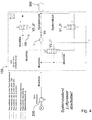
- FIG. 1 shows an electronic compressed air processing device 100 according to an embodiment of the invention.
- the compressed air processing device 100 serves to connect, on the one hand, to an air compressor device 200 that can be automatically switched to an idle state by means of compressed air from the compressed air processing device 100 (e.g. air compressor with what is known as an automatic idling system SLS; air compressor can automatically switch to idling) and, on the other hand, to connect to a compressed air system 300
- the compressed air processing device 100 and the air compressor device 200 are connected to one another via a conveying device (conveying line) FE.
- the conveying device FE leads into the compressed air processing device 100 via an input 1.
- the compressed air processing device 100 comprises a first valve V1 (electrically switchable solenoid valve), a second valve V2 (electrically switchable solenoid valve), a third valve V3 (air release valve), a fourth valve V4 (check valve) and a fifth valve V5 (throttle valve).
- the third valve V3 is used to selectively block or dispense air from the conveying device FE, controlled by compressed air.
- the air to be output by means of the third valve V3 can be led out of the compressed air processing device 100 via an outlet 3.
- the compressed air processing device 100 comprises an air processing device T, for. B. an air drying device for the regeneration of dry air in particular from the compressed air system 300.
- the third valve V3 is connected to the first valve V1 via a line section 1-3 in order to be switched from the first valve V1 by means of compressed air. Air from the compressed air system 300 can act on the third valve V3 via the first valve V1 when the first valve V1 is open in order to switch the third valve V3.
- the third valve V3 is connected to the second valve V2 via a line section 2-3 in order to be switched from the second valve V2 by means of compressed air. Air from the compressed air system 300 can act on the third valve V3 via the second valve V2 when the second valve V2 is open in order to switch the third valve V3.
- a connecting line VL branches off from the line section 2-3 and opens between the fourth valve V4 and the air processing device T.
- the connecting line VL comprises the fifth valve V5.
- FIG. 1 The mode of operation of the in Figure 1 system shown is described below with reference to FIG Figures 1 to 4 described, where Figure 1 the system status "quickly switch air compressor 200 from the idle phase to the delivery phase", Figure 2 the system status "conveying”, Figure 3 the system state “switch off air compressor 200 plus regeneration” and FIG. 4 shows the system state “switch off air compressor 200”.
- the second valve V2 is opened when the third valve V3 is open, whereby dry air from the compressed air system 300 parallel to the fourth valve V4 via the connection line VL and the fifth valve V5 through the air processing Device T for regeneration of the same can flow ( Figure 3 ).
- the system therefore provides for air from the compressed air system 300 to be fed back into the delivery device FE.
- This can be achieved by opening the second valve V2 when the third valve 3 is closed, so that air flows into the conveyor FE and the pressure exceeds a limit pressure of z. B. can usually rise about 2 bar. It follows from this that the air compressor device 200 can convey the full amount of air again more quickly and the pressure in the conveying device FE can exceed the system pressure more quickly.
- the energy freely available in an overrun phase can be stored more quickly in the compressed air system 300, even if the overrun phase is relatively short.
- the system consequently enables the use of particularly short overrun phases to obtain (recover) freely available energy within the overrun phases or for Conversion of freely available energy within the overrun phases into compressed air and subsequent storage in the compressed air system 300.
- the air compressor device 200 By feeding compressed air from the compressed air system 300 into the conveying device FE, the air compressor device 200 can be moved from an idle phase to a (full) conveying phase more quickly.
- the second valve V2 is switched from a blocked state "0" to an open state "1" from the idle phase, and always expediently only when a pressure increase is sensed by means of a pressure sensor S between the compressed air system 300 and the second valve V2 .
- the second valve V2 is precautionary and / or automatically switched to a blocked state "0" if a predefined time limit (e.g. between 10 to 30 seconds after opening the second valve V2) has elapsed and / or the system pressure between the second valve V2 and the compressed air system 300 falls below a predefined pressure limit (e.g. below 6 bar).
Description
- Die Erfindung betrifft ein Betriebsverfahren für eine insbesondere elektronische Druckluftaufbereitungseinrichtung für ein Nutzfahrzeug, z. B. einen Lastkraftwagen oder einen Omnibus. Die Erfindung betrifft zudem eine Druckluftaufbereitungseinrichtung, die zum Ausführen des Betriebsverfahrens konfiguriert ist.
- In Nutzfahrzeugen mit pneumatischem Druckluftsystem sind heute typischerweise Luftpresser installiert, die in irgendeiner Weise vom Förderbetrieb (Arbeitsbetrieb) in einen Energiesparbetrieb (Leerlaufbetrieb) mit reduzierter Förderleistung und dementsprechend reduzierter Leistungsaufnahme schaltbar sind. Die maximale Reduktion geschieht durch Betätigen einer Kupplung zwischen Motorabtrieb und Luftpresser. Eine teilweise Reduktion geschieht durch Betätigung eines Ventils im Luftpresser-Zylinderkopf, wodurch Ansaug- und Verdichtungsraum miteinander verbunden werden und dementsprechend eine stark reduzierte Verdichtung und Luftförderung stattfindet. Die Betätigung des Ventils geschieht üblicherweise über ein pneumatisches Steuersignal oder den Druck in einer Druckluft-führenden Förderleitung. Für letzteren Fall muss, um in den Energiesparmodus zu kommen, von einem nachfolgenden Lufttrockner oder einer elektronischen Luftaufbereitungseinheit ein Ablassventil geöffnet und damit die Förderleitung entlüftet werden. Ein Rückschlagventil stromabwärts des Ablassventils sichert den Druck in der Druckluftanlage. Typischerweise geschieht der Abschaltvorgang, wenn in der Druckluftanlage der maximal zulässige Systemdruck erreicht ist. Bei einem Druck in der Förderleitung unter z. B. üblicherweise ca. 2 bar schaltet das Ventil im Luftpresser-Zylinderkopf, wodurch Ansaug- und Verdichtungsraum miteinander verbunden werden. Der Luftpresser ist im Energiesparmodus, die reduzierte Fördermenge wird über das Ablassventil ins Freie entlüftet. Fällt nun allerdings der Systemdruck unter einen definierten Mindestdruck, muss das Ablassventil geschlossen werden. Damit steigt der Druck in der Förderleitung langsam wieder an. Es müssen üblicherweise ca. 2 Liter Volumen befüllt werden, nämlich die Förderleitung zwischen Luftpresser und Luftaufbereitungseinheit sowie eine Trockenmittelpatrone der Luftaufbereitungseinheit. Zu Beginn fördert der Luftpresser nur die reduzierte Luftmenge und erst oberhalb ca. 2 bar in der Förderleitung wieder die volle Luftmenge, wenn das Ventil im Luftpresser-Zylinderkopf die Verbindung zwischen Ansaug- und Verdichtungsraum schließt. Erst wenn der Druck in der Förderleitung über den aktuellen Systemdruck angestiegen ist, wird wieder Luft ins Druckluftsystem gefördert. Insbesondere wenn man Schubphasen (z. B. Bergabfahrt) ausnutzen will, vergeht durch die zunächst reduzierte Luftfördermenge relativ viel Zeit, bis man die verfügbare Energie im Druckluftsystem gespeichert hat. Bei kurzen Schubphasen kann es passieren, dass der Druck in der Förderleitung noch nicht über dem Systemdruck ist und somit quasi "ungesichert" über das Ablassventil wieder entlüftet wird und die Energie nicht gespeichert werden kann.
- Die
DE 10 2007 013673 A1 betrifft eine Druckluftversorgungseinrichtung für ein Nutzfahrzeug mit einem mit einem Kompressor koppelbaren Drucklufteingang, einer mit dem Drucklufteingang über eine Förderleitung gekoppelten Filtereinheit, einer mit einem Ablassausgang und der Förderleitung gekoppelten Ablassventileinrichtung, einem mit einem Steuereingang des Kompressors koppelbaren Energiesparsteuerausgang, einer zwischen dem Kompressor und der Filtereinheit angeordneten Förderleitungsabsperrventileinrichtung und einer ersten Ventileinrichtung sowie einer zweiten Ventileinrichtung. - Die
DE 10 2008 017361 A1 offenbart eine Druckluftversorgungseinrichtung zur Steuerung der Regeneration eines Luftfilters. - Die
EP 2 933 503 A1 offenbart ein Betriebsverfahren für eine zweckmäßig elektronische Druckluftaufbereitungseinrichtung zum Verbinden einerseits mit einer mittels Druckluft aus der Druckluftaufbereitungseinrichtung selbsttätig in einen Leerlaufzustand schaltbaren Luftkompressoreinrichtung und andererseits mit einem Druckluftsystem. - Die
WO 2008/095702 A1 offenbart eine Druckluftversorgungsanlage für ein Nutzfahrzeug, mit einer Lufttrocknereinheit mit einer Filtereinheit, einer elektrisch ansteuerbaren Ventileinheit und einer pneumatisch ansteuerbaren Ablassventileinheit, einem Kompressor mit Kupplung, welcher der Lufttrocknereinheit Druckluft über eine Förderleitung liefert, einer Mehrkreisschutzventileinheit, die Druckluft von der Lufttrocknereinheit bezieht, und einer elektrisch ansteuerbaren Kompressorkupplungsschaltventileinheit. Es ist eine elektronische Steuereinheit vorgesehen, die Funktionen der Lufttrocknereinheit und der Kompressorkupplungsschaltventileinheit steuert beziehungsweise regelt. - Eine Aufgabe der Erfindung ist es, ein Betriebsverfahren für eine zweckmäßig elektronische Druckluftaufbereitungseinrichtung für ein Nutzfahrzeug zu schaffen, mittels dessen insbesondere auch kurze Schubphasen zur Energiegewinnung oder Energiewandlung ausgenutzt werden können, insbesondere mittels dessen aus einer Leerlauf-/Energiesparphase heraus der Druck in einer Förderleitung schneller aufgebaut werden kann, z. B. über einen Grenzdruck von vorzugsweise ca. 2 bar.
- Diese Aufgabe kann mit den Merkmalen des Hauptanspruchs gelöst werden. Vorteilhafte Weiterbildungen der Erfindung können den Unteransprüchen und der nachfolgenden Beschreibung entnommen werden.
- Die Erfindung schafft ein Betriebsverfahren für eine insbesondere elektronische Druckluftaufbereitungseinrichtung zum Verbinden mit einer mittels Druckluft aus der Druckluftaufbereitungseinrichtung selbsttätig in einen Leerlaufzustand schaltbaren Luftkompressoreinrichtung (z. B. Kompressor mit sogenanntem selbsttätigen Leerlaufsystem (SLS)) und mit einem Druckluftsystem.
- Die Druckluftaufbereitungseinrichtung umfasst eine mit der Luftkompressoreinrichtung verbindbare Fördereinrichtung (z. B. eine Förderleitung), ein erstes Ventil, ein zweites Ventil, ein drittes Ventil und ein viertes Ventil.
- Aus einer Leerlaufphase (z. B. Energiesparphase) heraus hin zu einer Förderphase (z. B. Arbeitsphase) werden das erste Ventil und das dritte Ventil in einen gesperrten Zustand geschaltet und das zweite Ventil in einen geöffneten Zustand geschaltet. Dadurch kann Luft aus dem Druckluftsystem über das zweite Ventil und unter Umgehung des vierten Ventils zurück zur Fördereinrichtung geführt werden, um insbesondere den Luftdruck in der Fördereinrichtung aus der Leerlaufphase heraus ausgehend von einer drucklosen Fördereinrichtung aufbauen zu können. Dadurch kann Energie aus Schubphasen (z .B. Bergabfahrt), insbesondere selbst kurzen Schubphasen von z. B. unter 30 Sekunden, unter 15 Sekunden oder sogar unter 5 Sekunden, in Druckluft gewandelt und im Druckluftsystem gespeichert werden.
- Es ist möglich, dass das zweite Ventil aus der Leerlaufphase heraus von einem gesperrten Zustand in einen geöffneten Zustand geschaltet wird und (z. B. immer und erst) wieder in einen gesperrten Zustand, wenn z. B. mittels eines Drucksensors ein Druckanstieg in einem Leitungsabschnitt zwischen dem zweiten Ventil und dem Druckluftsystem erfasst wird. Problematisch dabei ist, dass insbesondere wenn während der Betätigung des zweiten Ventils ("geöffneter Zustand") ein Fehlerfall eintritt (z. B. eine Systemleckage, Abriss einer Förderleitung und/oder Steckenbleiben des dritten Ventils in geöffnetem Zustand, etc.), es nicht zu einem Druckanstieg kommen würde. Hingegen würde die Funktion des vierten Ventils umgangen und der Druck im Druckluftsystem permanent fallen bis zum Schließdruck der jeweiligen Kreise, was insbesondere zu einer Stop-Meldung führen würde. Die Wahrscheinlichkeit, dass ein solcher Fehlerfall eintritt, insbesondere während der Betätigung des zweiten Ventils, ist zwar gering, dennoch ist ein solcher Fehlerfall möglich.
- Das zweite Ventil kann deshalb in einen gesperrten Zustand geschaltet werden, wenn ein vordefiniertes Zeitlimit (z. B. zwischen 10 bis 30 Sekunden) verstrichen ist und/oder ein Systemdruck (zweckmäßig Luftdruck) zwischen dem zweiten Ventil und dem Druckluftsystem unter ein vordefiniertes Drucklimit sinkt. Dadurch kann insbesondere das zweite Ventil in einen gesperrten Zustand versetzt werden, auch wenn kein Druckanstieg zwischen dem zweiten Ventil und dem Druckluftsystem gemessen wird.
- Das Zeitlimit kann z. B. maximal 10, maximal 15, maximal 20, maximal 25 oder maximal 30 Sekunden betragen, so dass zweckmäßig nach Ablauf von z. B. maximal 10, maximal 15, maximal 20, maximal 25 oder maximal 30 Sekunden das zweite Ventil in einen gesperrten Zustand geschaltet wird.
- Das Zeitlimit beginnt vorzugsweise zu laufen, wenn das zweite Ventil in einen geöffneten Zustand geschalten wird
- Das vordefinierte Drucklimit kann z. B. mindestens 6bar, mindestens 7bar oder mindestens 8bar betragen, so dass zweckmäßig nach einem Druckabfall unter mindestens 5bar, mindestens 6bar, mindestens 7bar oder mindestens 8bar das zweite Ventil in einen gesperrten Zustand geschaltet wird.
- Es ist möglich, dass sich das Zeitlimit längstens bis zu dem Zeitpunkt erstreckt, wenn der Systemdruck, vorzugsweise zwischen dem zweiten Ventil und dem Druckluftsystem, auf mindestens 5bar, mindestens 6bar, mindestens 7bar oder mindestens 8bar sinkt.
- Es ist möglich, dass das zweite Ventil aus der Leerlaufphase heraus von einem gesperrten Zustand in einen geöffneten Zustand geschaltet wird und wieder in einen gesperrten Zustand geschaltet wird, wenn das vordefinierte Zeitlimit verstrichen ist und/oder der Systemdruck, vorzugsweise zwischen dem zweiten Ventil und dem Druckluftsystem, unter das vordefinierte Drucklimit sinkt.
- Der Systemdruck zwischen dem zweiten Ventil und dem Druckluftsystem wird zweckmäßig durch einen Drucksensor erfasst, insbesondere im Leitungsabschnitt zwischen dem zweiten Ventil und dem Druckluftsystem.
- Es ist möglich, dass aus der Leerlaufphase heraus die Luft aus dem Druckluftsystem über eine Verbindungsleitung in einen Leitungsabschnitt der Druckluftaufbereitungseinrichtung zwischen dem vierten Ventil und einer Luft-Aufbereitungs- oder Luft-Trocknungseinrichtung geführt wird und über die Luft-Aufbereitungs- oder Luft-Trocknungseinrichtung zurück zur Fördereinrichtung geführt wird.
- Die Verbindungsleitung zweigt vorzugsweise von einem das zweite Ventil mit dem dritten Ventil verbindenden Leitungsabschnitt ab und mündet zwischen dem vierten Ventil und der Luft-Aufbereitungs- oder Luft-Trocknungseinrichtung.
- Die Verbindungsleitung kann ein Drosselventil aufweisen, das ein fünftes Ventil der Druckluftaufbereitungseinrichtung darstellt.
- Das erste Ventil und/oder das zweite Ventil ist ein vorzugsweise elektrisch schaltbares Schaltventil, vorzugsweise ein Magnetventil.
- Es ist möglich, dass Luft aus dem Druckluftsystem über das erste Ventil auf das dritte Ventil wirkt, wenn das erste Ventil geöffnet ist, um das dritte Ventil zu schalten. Das dritte Ventil steht zweckmäßig über einen Leitungsabschnitt mit dem ersten Ventil in Verbindung, um mittels Druckluft aus dem Druckluftsystem und/oder aus dem ersten Ventil geschaltet zu werden.
- Ferner kann Luft aus dem Druckluftsystem über das zweite Ventil auf das dritte Ventil wirken, wenn das zweite Ventil geöffnet ist, um das dritte Ventil zu schalten. Das dritte Ventil steht zweckmäßig über einen Leitungsabschnitt mit dem zweiten Ventil in Verbindung, um mittels Druckluft aus dem Druckluftsystem und/oder aus dem zweiten Ventil geschaltet zu werden.
- Das dritte Ventil ist folglich zweckmäßig sowohl über das erste Ventil als auch über das zweite Ventil mittels Druckluft aus dem Druckluftsystem ansteuerbar.
- Das dritte Ventil ist vorzugsweise ein Luft-Ablassventil zum wahlweisen Sperren oder Ausgeben von Luft aus der Fördereinrichtung und/oder ein Druckluft-schaltbares Ventil, insbesondere Druckluft-schaltbar über Luft aus dem ersten Ventil und dem zweiten Ventil.
- Das vierte Ventil ist hingegen vorzugsweise ein Rückschlagventil.
- Das vierte Ventil kann z. B. eine Durchfuhr von Luft aus der Fördereinrichtung in Richtung Druckluftsystem erlauben, hingegen eine Durchfuhr von Luft aus dem Druckluftsystem in Richtung Fördereinrichtung verhindern.
- Die Druckluftaufbereitungseinrichtung kann einen Drucksensor zur Erfassung des Luftdrucks zwischen dem zweiten Ventil und dem Druckluftsystem aufweisen. Das zweite Ventil kann in Abhängigkeit der mittels des Drucksensors erfassten Werte geschaltet werden.
- Zu erwähnen ist, dass das Merkmal "Luft" im Rahmen der Erfindung breit zu verstehen ist und vorzugsweise auch andere Gase umfassen kann.
- Zu erwähnen ist ferner, dass das Merkmal "Leerlaufphase" eine "Energiesparphase" umfassen und das Merkmal "Förderphase" eine "Arbeitsphase" umfassen kann.
- Die zuvor beschriebenen bevorzugten Ausführungsformen und Merkmale der Erfindung sind beliebig miteinander kombinierbar. Andere vorteilhafte Weiterbildungen der Erfindung sind in den Unteransprüchen offenbart oder ergeben sich aus der folgenden Beschreibung bevorzugter Ausführungsformen der Erfindung in Verbindung mit den beigefügten Figuren.
- Figur 1
- zeigt eine schematische Darstellung einer Druckluftaufbereitungseinrichtung gemäß einer Ausführungsform der Erfindung, in einem Systemzustand "Luftpresser schnell aus Leerlaufphase in Förderphase schalten",
- Figur 2
- zeigt die Druckluftaufbereitungseinrichtung der
Figur 1 , im Systemzustand "Fördern", - Figur 3
- zeigt die Druckluftaufbereitungseinrichtung der
Figuren 1 und2 , im Systemzustand "Luftpresser abschalten plus regenerieren", und - Figur 4
- zeigt die Druckluftaufbereitungseinrichtung der
Figuren 1 bis 3 , im Systemzustand "Luftpresser abschalten". -
Figur 1 zeigt eine elektronische Druckluftaufbereitungseinrichtung 100 gemäß einer Ausführungsform der Erfindung. Die Druckluftaufbereitungseinrichtung 100 dient zum Verbinden einerseits mit einer mittels Druckluft aus der Druckluftaufbereitungseinrichtung 100 selbsttätig in einen Leerlaufzustand schaltbaren Luftkompressoreinrichtung 200 (z. B. Luftpresser mit sogenanntem selbsttätigen Leerlaufsystem SLS; Luftpresser kann sich selbsttätig in Leerlauf schalten) und zum Verbinden andererseits mit einem Druckluftsystem 300. Die Druckluftaufbereitungseinrichtung 100 und die Luftkompressoreinrichtung 200 sind über eine Fördereinrichtung (Förderleitung) FE miteinander verbunden. Die Fördereinrichtung FE führt über einen Eingang 1 in die Druckluftaufbereitungseinrichtung 100. - Die Druckluftaufbereitungseinrichtung 100 umfasst ein erstes Ventil V1 (elektrisch schaltbares Magnetventil), ein zweites Ventil V2 (elektrisch schaltbares Magnetventil), ein drittes Ventil V3 (Luft-Ablassventil), ein viertes Ventil V4 (Rückschlagventil) und ein fünftes Ventil V5 (Drosselventil). Das dritte Ventil V3 dient zum druckluftgesteuerten, wahlweisen Sperren oder Ausgeben von Luft aus der Fördereinrichtung FE. Die mittels des dritten Ventils V3 auszugebende Luft kann über einen Ausgang 3 aus der Druckluftaufbereitungseinrichtung 100 hinausgeführt werden.
- Die Druckluftaufbereitungseinrichtung 100 umfasst eine Luft-Aufbereitungs-Einrichtung T, z. B. eine Luft-Trocknungs-Einrichtung, zur Regeneration insbesondere trockener Luft aus dem Druckluftsystem 300.
- Das dritte Ventil V3 steht über einen Leitungsabschnitt 1-3 mit dem ersten Ventil V1 in Verbindung, um mittels Druckluft aus dem ersten Ventil V1 geschaltet zu werden. Luft aus dem Druckluftsystem 300 kann über das erste Ventil V1 auf das dritte Ventil V3 wirken, wenn das erste Ventil V1 geöffnet ist, um das dritte Ventil V3 zu schalten.
- Das dritte Ventil V3 steht über einen Leitungsabschnitt 2-3 mit dem zweiten Ventil V2 in Verbindung, um mittels Druckluft aus dem zweiten Ventil V2 geschaltet zu werden. Luft aus dem Druckluftsystem 300 kann über das zweite Ventil V2 auf das dritte Ventil V3 wirken, wenn das zweite Ventil V2 geöffnet ist, um das dritte Ventil V3 zu schalten.
- Eine Verbindungsleitung VL zweigt von dem Leitungsabschnitt 2-3 ab und mündet zwischen dem vierten Ventil V4 und der Luft-Aufbereitungs-Einrichtung T. Die Verbindungsleitung VL umfasst das fünfte Ventil V5.
- Die Betriebsweise des in
Figur 1 gezeigten Systems wird nachfolgend unter Bezugnahme auf dieFiguren 1 bis 4 beschrieben, wobeiFigur 1 den Systemzustand "Luftpresser 200 schnell aus der Leerlaufphase in die Förderphase schalten",Figur 2 den Systemzustand "Fördern",Figur 3 den Systemzustand "Luftpresser 200 abschalten plus regenieren" und Figur 4 den Systemzustand "Luftpresser 200 abschalten" zeigt. - Ausgehend von einer Leerlauf- bzw. Energiesparphase (
Figur 4 ) hin zu einer Förder- bzw. Arbeitsphase (Figur 2 ) wird das erste Ventil V1 und das dritte Ventil V3 in einen gesperrten Zustand "0" geschaltet und das zweite Ventil V2 in einen geöffneten Zustand "1" geschaltet (Figur 1 ), so dass Luft aus dem Druckluftsystem 300 über das zweite Ventil V2 und unter Umgehung des vierten Ventils V4 - also parallel zum vierten Ventil V4 - zurück zur Fördereinrichtung FE geführt wird, wodurch die zunächst drucklose Fördereinrichtung FE mit Druck beaufschlagt wird. Somit kann aus der Leerlaufphase heraus der Druck in der Fördereinrichtung FE schneller aufgebaut werden, um die (energiearme) Druckluftförderung während insbesondere kurzer Schubphasen des Nutzfahrzeugs besser ausnutzen zu können. Selbst Schubphasen von z. B. unter 30 s, unter 15 s oder sogar unter 5 s können energiegewinnend genutzt werden. Um trockene Luft aus dem Druckluftsystem 300 zu regenerieren, wird hingegen das zweite Ventil V2 bei geöffnetem dritten Ventil V3 geöffnet, wodurch trockene Luft aus dem Druckluftsystem 300 parallel zum vierten Ventil V4 über die Verbindungsleitung VL und das fünfte Ventil V5 durch die Luft-Aufbereitungs-Einrichtung T zur Regeneration derselben strömen kann (Figur 3 ). - Das System sieht also vor, Luft aus dem Druckluftsystem 300 in die Fördereinrichtung FE zurückzuspeisen. Das kann eben dadurch realisiert werden, dass bei geschlossenem dritten Ventil 3 das zweite Ventil V2 geöffnet wird, so dass Luft in die Fördereinrichtung FE strömt und der Druck schneller über einen Grenzdruck von z. B. üblicherweise ca. 2 bar steigen kann. Daraus folgt, dass die Luftkompressoreinrichtung 200 schneller wieder die volle Luftmenge fördern kann und der Druck in der Fördereinrichtung FE schneller den Systemdruck übersteigen kann. Die in einer Schubphase frei verfügbare Energie kann schneller im Druckluftsystem 300 gespeichert werden, selbst dann, wenn die Schubphase relativ kurz ist.
- Das System ermöglicht folglich die Ausnutzung insbesondere kurzer Schubphasen zur Gewinnung (Rückgewinnung) frei verfügbarer Energie innerhalb der Schubphasen bzw. zur Wandlung frei verfügbarer Energie innerhalb der Schubphasen in Druckluft und anschließender Speicherung im Druckluftsystem 300. Durch Einspeisen von Druckluft aus dem Druckluftsystem 300 in die Fördereinrichtung FE kann die Luftkompressoreinrichtung 200 schneller aus einer Leerlaufphase in eine (volle) Förderphase versetzt werden.
- Das zweite Ventil V2 wird aus der Leerlaufphase heraus von einem gesperrten Zustand "0" in einen geöffneten Zustand "1" geschaltet und zwar zweckmäßig immer und erst dann, wenn zwischen dem Druckluftsystem 300 und dem zweiten Ventil V2 ein Druckanstieg mittels eines Drucksensors S sensiert wird. Für einen potentiellen Fehlerfall, in dessen Folge kein Druckanstieg zwischen dem Druckluftsystem 300 und dem zweiten Ventil V2 erfolgt, wird das zweite Ventil V2 vorsorglich und/oder automatisch in einen gesperrten Zustand "0" geschaltet, wenn ein vordefiniertes Zeitlimit (z. B. zwischen 10 bis 30 Sekunden nach Öffnen des zweiten Ventils V2) verstrichen ist und/oder der Systemdruck zwischen dem zweiten Ventil V2 und dem Druckluftsystem 300 unter ein vordefiniertes Drucklimit (z. B. unter 6bar) fällt.
- Die Erfindung ist nicht auf die oben beschriebenen bevorzugten Ausführungsformen beschränkt. Vielmehr ist eine Vielzahl von Varianten und Abwandlungen möglich, die ebenfalls von dem Erfindungsgedanken Gebrauch machen und deswegen in den Schutzbereich fallen. Darüber hinaus beansprucht die Erfindung Schutz für den Gegenstand und die Merkmale der Unteransprüche, unabhängig von den in Bezug genommenen Merkmalen und Ansprüchen.
-
- 100
- Druckluftaufbereitungseinrichtung
- 200
- Luftkompressoreinrichtung (Luftpresser)
- 300
- Druckluftsystem
- V1
- Erstes Ventil
- V2
- Zweites Ventil
- V3
- Drittes Ventil
- V4
- Viertes Ventil
- V5
- Fünftes Ventil
- FE
- Fördereinrichtung (Förderleitung)
- T
- Luft-Aufbereitungs- oder Luft-Trocknungseinrichtung
- VL
- Verbindungsleitung
- 1-3
- Verbindungsleitung (erstes Ventil - drittes Ventil)
- 2-3
- Verbindungsleitung (zweites Ventil - drittes Ventil)
- S
- Drucksensor
- "0"
- Gesperrter Zustand
- "1"
- Geöffneter Zustand
- M
- Motor
Claims (14)
- Betriebsverfahren für eine vorzugsweise elektronische Druckluftaufbereitungseinrichtung (100) zum Verbinden einerseits mit einer mittels Druckluft aus der Druckluftaufbereitungseinrichtung (100) selbsttätig in einen Leerlaufzustand schaltbaren Luftkompressoreinrichtung (200) und andererseits mit einem Druckluftsystem (300), wobei die Druckluftaufbereitungseinrichtung (100) eine mit der Luftkompressoreinrichtung (200) verbindbare Fördereinrichtung (FE), ein erstes Ventil (V1), ein zweites Ventil (V2), ein drittes Ventil (V3) und ein viertes Ventil (V4) aufweist, wobei aus einer Leerlaufphase heraus hin zu einer Förderphase das erste Ventil (V1) und das dritte Ventil (V3) in einen gesperrten Zustand ("0") geschaltet werden und das zweite Ventil (V2) in einen geöffneten Zustand ("1") geschaltet wird, so dass Luft aus dem Druckluftsystem (300) über das zweite Ventil (V2) und unter Umgehung des vierten Ventils (V4) zurück zur Fördereinrichtung (FE) geführt wird, wobei das zweite Ventil (V2) in einen gesperrten Zustand ("0") geschaltet wird, wenn ein vordefiniertes Zeitlimit verstrichen ist und/oder ein Systemdruck zwischen dem zweiten Ventil (V2) und dem Druckluftsystem (300) unter ein vordefiniertes Drucklimit sinkt.
- Betriebsverfahren nach Anspruch 1, wobei das Zeitlimit maximal 10, maximal 15, maximal 20, maximal 25 oder maximal 30 Sekunden beträgt.
- Betriebsverfahren nach Anspruch 1 oder 2, wobei das Drucklimit mindestens 5bar, mindestens 6bar, mindestens 7bar oder mindestens 8bar beträgt.
- Betriebsverfahren nach einem der vorhergehenden Ansprüche, wobei sich das Zeitlimit bis zu dem Zeitpunkt erstreckt, wenn der Systemdruck, zwischen dem zweiten Ventil (V2) und dem Druckluftsystem (300), auf zumindest 6bar, zumindest 7bar oder zumindest 8bar sinkt.
- Betriebsverfahren nach einem der vorhergehenden Ansprüche, wobei das zweite Ventil (V2) aus der Leerlaufphase heraus von einem gesperrten Zustand ("0") in einen geöffneten Zustand ("1") geschaltet wird und wieder in einen gesperrten Zustand ("0") geschaltet wird, wenn das vordefinierte Zeitlimit verstrichen ist und/oder der Systemdruck unter das vordefinierte Drucklimit sinkt.
- Betriebsverfahren nach einem der vorhergehenden Ansprüche, wobei die Luft aus dem Druckluftsystem (300) über eine Verbindungsleitung (VL) in einen Leitungsabschnitt der Druckluftaufbereitungseinrichtung (100) zwischen dem vierten Ventil (V4) und einer Luft-Aufbereitungs- oder Luft-Trocknungseinrichtung (T) geführt wird und über die Luft-Aufbereitungs- oder Luft-Trocknungseinrichtung (T) zurück zur Fördereinrichtung (FE).
- Betriebsverfahren nach Anspruch 6, wobei die Verbindungsleitung (VL) ein Drosselventil (V5) aufweist.
- Betriebsverfahren nach einem der vorhergehenden Ansprüche, wobei das zweite Ventil (V2) aus der Leerlaufphase heraus von einem gesperrten Zustand ("0") in einen geöffneten Zustand ("1") geschaltet wird und wieder in einen gesperrten Zustand ("0") geschaltet wird, wenn ein Druckanstieg zwischen dem zweiten Ventil (V2) und dem Druckluftsystem (300) erfasst wird.
- Betriebsverfahren nach einem der vorhergehenden Ansprüche, wobei
das erste Ventil (V1) ein elektrisch schaltbares Schaltventil ist, vorzugsweise ein Magnetventil,
das zweite Ventil (V2) ein elektrisch schaltbares Schaltventil ist, vorzugsweise ein Magnetventil, und/oder
das vierte Ventil (V4) ein Rückschlagventil ist. - Betriebsverfahren nach einem der vorhergehenden Ansprüche, wobei Luft aus dem Druckluftsystem (300) über das erste Ventil (V1) auf das dritte Ventil (V3) wirkt, wenn das erste Ventil (V1) geöffnet (1") ist, um das dritte Ventil (V3) zu schalten.
- Betriebsverfahren nach einem der vorhergehenden Ansprüche, wobei Luft aus dem Druckluftsystem (300) über das zweite Ventil (V2) auf das dritte Ventil (V3) wirkt, wenn das zweite Ventil (V2) geöffnet (1") ist, um das dritte Ventil (V3) zu schalten.
- Betriebsverfahren nach einem der vorhergehenden Ansprüche, wobei das dritte Ventil (V3) ein Luft-Ablassventil zum wahlweisen Sperren oder Ausgeben von Luft aus der Fördereinrichtung (FE) ist und/oder druckluftschaltbar ist, insbesondere über Luft aus dem Druckluftsystem (300).
- Betriebsverfahren nach einem der vorhergehenden Ansprüche, wobei das vierte Ventil (V4) eine Durchfuhr von Luft aus der Fördereinrichtung (FE) zu dem Druckluftsystem (300) erlaubt und eine Durchfuhr von Luft aus dem Druckluftsystem (300) zu der Fördereinrichtung (FE) verhindert.
- Betriebsverfahren nach einem der vorhergehenden Ansprüche, wobei die Druckluftaufbereitungseinrichtung (100) einen Drucksensor (S) zur Erfassung des Systemdrucks zwischen dem zweiten Ventil (V2) und dem Druckluftsystem (300) aufweist und/oder das zweite Ventil (V2) in Abhängigkeit der mittels des Drucksensors (S) erfassten Werte geschaltet wird.
Priority Applications (1)
| Application Number | Priority Date | Filing Date | Title |
|---|---|---|---|
| PL16001582T PL3128186T3 (pl) | 2015-08-06 | 2016-07-15 | Sposób sterowania działaniem urządzenia do zapewniania sprężonego powietrza dla pojazdu użytkowego |
Applications Claiming Priority (1)
| Application Number | Priority Date | Filing Date | Title |
|---|---|---|---|
| DE102015010347.4A DE102015010347A1 (de) | 2015-08-06 | 2015-08-06 | Betriebsverfahren für eine Druckluftaufbereitungseinrichtung für ein Nutzfahrzeug |
Publications (2)
| Publication Number | Publication Date |
|---|---|
| EP3128186A1 EP3128186A1 (de) | 2017-02-08 |
| EP3128186B1 true EP3128186B1 (de) | 2021-02-24 |
Family
ID=56799171
Family Applications (1)
| Application Number | Title | Priority Date | Filing Date |
|---|---|---|---|
| EP16001582.2A Active EP3128186B1 (de) | 2015-08-06 | 2016-07-15 | Betriebsverfahren für eine druckluftaufbereitungseinrichtung für ein nutzfahrzeug |
Country Status (7)
| Country | Link |
|---|---|
| EP (1) | EP3128186B1 (de) |
| CN (1) | CN106427943B (de) |
| BR (1) | BR102016018053B1 (de) |
| DE (1) | DE102015010347A1 (de) |
| HU (1) | HUE053528T2 (de) |
| PL (1) | PL3128186T3 (de) |
| RU (1) | RU2717467C2 (de) |
Families Citing this family (4)
| Publication number | Priority date | Publication date | Assignee | Title |
|---|---|---|---|---|
| DE102017129908A1 (de) | 2017-12-14 | 2019-06-19 | Knorr-Bremse Systeme für Nutzfahrzeuge GmbH | Anordnung für ein Nutzfahrzeug |
| DE102018103595A1 (de) | 2018-02-19 | 2019-08-22 | Man Truck & Bus Ag | Vorrichtung zur Erzeugung von Druckluft |
| DE102018112521A1 (de) * | 2018-05-24 | 2019-11-28 | Knorr-Bremse Systeme für Nutzfahrzeuge GmbH | Luftaufbereitungseinrichtung mit elektronischer Steuereinheit zur Versorgung mindestens eines Verbraucherkreises eines Fahrzeuges |
| CN114852025B (zh) * | 2022-06-21 | 2023-07-07 | 山推工程机械股份有限公司 | 一种纯电装载机用辅助制动控制系统 |
Family Cites Families (11)
| Publication number | Priority date | Publication date | Assignee | Title |
|---|---|---|---|---|
| SU1701586A1 (ru) * | 1990-01-08 | 1991-12-30 | Харьковский Автомобильно-Дорожный Институт Им.Комсомола Украины | Пневматический тормозной привод транспортного средства с двигателем внутреннего сгорани |
| RU421U1 (ru) * | 1992-02-24 | 1995-05-16 | Акционерное общество "Камский автомобильный завод" | Система охлаждения пневмогидравлических механизмов |
| DE102005057004B3 (de) * | 2005-11-30 | 2007-04-05 | Knorr-Bremse Systeme für Nutzfahrzeuge GmbH | Druckluftaufbereitungseinrichtung und Verfahren zum Betreiben einer Druckluftaufbereitungseinrichtung |
| DE102008004807B4 (de) * | 2007-02-07 | 2012-10-31 | Knorr-Bremse Systeme für Nutzfahrzeuge GmbH | Druckluftversorgungsanlage und Verfahren zum Betreiben einer Druckluftversorgungsanlage |
| DE102007013673B4 (de) * | 2007-03-19 | 2009-07-02 | Knorr-Bremse Systeme für Nutzfahrzeuge GmbH | Druckluftversorgungseinrichtung für ein Nutzfahrzeug und Verfahren zum Betreiben einer Druckluftversorgungseinrichtung |
| DE102008017361B4 (de) * | 2008-04-04 | 2010-04-01 | Knorr-Bremse Systeme für Nutzfahrzeuge GmbH | Druckluftversorgungseinrichtung mit Material schonender Regenerationsfähigkeit |
| DE102010009035A1 (de) * | 2010-02-24 | 2011-08-25 | WABCO GmbH, 30453 | Druckluftaufbereitungseinrichtung für Kraftfahrzeuge |
| DE102011083614A1 (de) * | 2011-03-01 | 2012-09-06 | Continental Teves Ag & Co. Ohg | Trocknerschaltung für eine pneumatische Regelvorrichtung eines Fahrzeugs |
| DE102012001736A1 (de) * | 2012-01-31 | 2013-08-01 | Wabco Gmbh | Druckluftversorgungsanlage, pneumatisches System und Verfahren zum Betreiben einer Druckluftversorgungsanlage bzw. eines pneumatischen Systems |
| DE102012001734B4 (de) * | 2012-01-31 | 2020-11-12 | Wabco Gmbh | Druckluftversorgungsanlage, pneumatisches System und Verfahren zum Betreiben einer Druckluftversorgungsanlage bzw. eines pneumatischen Systems |
| DE102014003927A1 (de) * | 2014-03-19 | 2015-09-24 | Man Truck & Bus Ag | Betriebsverfahren für eine Druckluftaufbereitungseinrichtung für ein Nutzfahrzeug |
-
2015
- 2015-08-06 DE DE102015010347.4A patent/DE102015010347A1/de not_active Withdrawn
-
2016
- 2016-07-15 PL PL16001582T patent/PL3128186T3/pl unknown
- 2016-07-15 EP EP16001582.2A patent/EP3128186B1/de active Active
- 2016-07-15 HU HUE16001582A patent/HUE053528T2/hu unknown
- 2016-08-03 BR BR102016018053-8A patent/BR102016018053B1/pt active IP Right Grant
- 2016-08-04 RU RU2016132143A patent/RU2717467C2/ru active
- 2016-08-05 CN CN201610635459.8A patent/CN106427943B/zh active Active
Non-Patent Citations (1)
| Title |
|---|
| None * |
Also Published As
| Publication number | Publication date |
|---|---|
| BR102016018053A2 (pt) | 2017-02-07 |
| BR102016018053B1 (pt) | 2022-11-29 |
| HUE053528T2 (hu) | 2021-07-28 |
| CN106427943B (zh) | 2020-10-02 |
| DE102015010347A1 (de) | 2017-02-09 |
| PL3128186T3 (pl) | 2021-07-05 |
| EP3128186A1 (de) | 2017-02-08 |
| RU2016132143A (ru) | 2018-02-08 |
| CN106427943A (zh) | 2017-02-22 |
| RU2717467C2 (ru) | 2020-03-23 |
| RU2016132143A3 (de) | 2020-01-21 |
Similar Documents
| Publication | Publication Date | Title |
|---|---|---|
| EP2407231B1 (de) | Druckluftaufbereitungseinrichtung mit zwei Lufttrocknungskartuschen | |
| DE102005057004B3 (de) | Druckluftaufbereitungseinrichtung und Verfahren zum Betreiben einer Druckluftaufbereitungseinrichtung | |
| EP3128186B1 (de) | Betriebsverfahren für eine druckluftaufbereitungseinrichtung für ein nutzfahrzeug | |
| EP2129565B1 (de) | Druckluftversorgungseinrichtung für ein nutzfahrzeug und verfahren zum betreiben einer druckluftversorgungseinrichtung | |
| EP2933503B1 (de) | Betriebsverfahren für eine Druckluftaufbereitungseinrichtung für ein Nutzfahrzeug | |
| DE102011107155B4 (de) | Druckluftaufbereitungsanlage und Verfahren zum Betreiben einer Druckluftaufbereitungsanlage | |
| EP2829744B1 (de) | Luftbeschaffungsvorrichtung für ein Druckluftsystem eines Fahrzeugs und derartiges Druckluftsystem | |
| EP1042151A1 (de) | Elektronische druckluftaufbereitungsanlage | |
| DE102010024476A1 (de) | Druckluftsteuerungseinrichtung, Druckluftsteuerungsverfahren, elektronische Steuereinrichtung, Druckluftversorgungssystem, Druckluftversorgungsverfahren und Fahrzeug | |
| EP1807296B1 (de) | Druckluftversrogungseinrichtung und verfahren zum betreiben einer durchluftversorgungseinrichtung | |
| EP2686215B1 (de) | Lufttrockneradaptermodul, lufttrocknermodul und druckluftversorgungseinrichtung | |
| EP3619065B1 (de) | Verfahren zum betreiben einer druckregelanlage mit einem mehrstufigen kompressor, sowie druckregelanlage | |
| WO2017144147A1 (de) | Druckluftversorgungsanlage eines fahrzeugs | |
| DE102005057003A1 (de) | Druckluftversorgungsanlage und Verfahren zum Betreiben einer Druckluftversorgungsanlage | |
| WO2019115028A1 (de) | Druckluftversorgungsanlage zum betreiben einer pneumatikanlage, verfahren und fahrzeug | |
| EP1479584B1 (de) | Mehrkreisschutzventileinrichtung mit magnetventilgesteuerter Druckbegrenzersteuerung für druckluftbetätigte Aktuatoren eines Fahrzeugs | |
| EP2675674B1 (de) | Druckluftversorgungseinrichtung für nutzfahrzeuge | |
| EP1964743B1 (de) | Druckluftversorgungseinrichtung für ein nutzfahrzeug und verfahren zum betreiben einer druckluftversorgungseinrichtung | |
| DE102007005987B4 (de) | Ventileinrichtung für eine Druckluftversorgungseinrichtung und Druckluftversorgungsanlage | |
| WO2012084517A1 (de) | Ventileinrichtung zur steuerung der luftzufuhr für einen kompressor eines fahrzeugs sowie kompressorsystem und verfahren zur steuerung eines kompressorsystems | |
| WO2017157503A1 (de) | Trocknungseinrichtung einer druckluftversorgungsanlage | |
| EP1964742A2 (de) | Druckluftversorgungseinrichtung für ein Nutzfahrzeug und Verfahren zum Betreiben einer Druckluftversorgungseinrichtung | |
| EP1640232B1 (de) | Druckluft-Versorgungseinrichtung für eine Druckluftanlage in einem Nutzfahrzeug | |
| EP3371021A1 (de) | Druckluftaufbereitungseinrichtung und verfahren zum betreiben einer solchen | |
| EP2193966B1 (de) | Feststellbremsanlage für ein Nutzfahrzeug |
Legal Events
| Date | Code | Title | Description |
|---|---|---|---|
| PUAI | Public reference made under article 153(3) epc to a published international application that has entered the european phase |
Free format text: ORIGINAL CODE: 0009012 |
|
| STAA | Information on the status of an ep patent application or granted ep patent |
Free format text: STATUS: THE APPLICATION HAS BEEN PUBLISHED |
|
| AK | Designated contracting states |
Kind code of ref document: A1 Designated state(s): AL AT BE BG CH CY CZ DE DK EE ES FI FR GB GR HR HU IE IS IT LI LT LU LV MC MK MT NL NO PL PT RO RS SE SI SK SM TR |
|
| AX | Request for extension of the european patent |
Extension state: BA ME |
|
| STAA | Information on the status of an ep patent application or granted ep patent |
Free format text: STATUS: REQUEST FOR EXAMINATION WAS MADE |
|
| 17P | Request for examination filed |
Effective date: 20170511 |
|
| RBV | Designated contracting states (corrected) |
Designated state(s): AL AT BE BG CH CY CZ DE DK EE ES FI FR GB GR HR HU IE IS IT LI LT LU LV MC MK MT NL NO PL PT RO RS SE SI SK SM TR |
|
| RAP1 | Party data changed (applicant data changed or rights of an application transferred) |
Owner name: MAN TRUCK & BUS SE |
|
| STAA | Information on the status of an ep patent application or granted ep patent |
Free format text: STATUS: EXAMINATION IS IN PROGRESS |
|
| 17Q | First examination report despatched |
Effective date: 20200214 |
|
| GRAP | Despatch of communication of intention to grant a patent |
Free format text: ORIGINAL CODE: EPIDOSNIGR1 |
|
| STAA | Information on the status of an ep patent application or granted ep patent |
Free format text: STATUS: GRANT OF PATENT IS INTENDED |
|
| INTG | Intention to grant announced |
Effective date: 20201027 |
|
| GRAS | Grant fee paid |
Free format text: ORIGINAL CODE: EPIDOSNIGR3 |
|
| GRAA | (expected) grant |
Free format text: ORIGINAL CODE: 0009210 |
|
| STAA | Information on the status of an ep patent application or granted ep patent |
Free format text: STATUS: THE PATENT HAS BEEN GRANTED |
|
| AK | Designated contracting states |
Kind code of ref document: B1 Designated state(s): AL AT BE BG CH CY CZ DE DK EE ES FI FR GB GR HR HU IE IS IT LI LT LU LV MC MK MT NL NO PL PT RO RS SE SI SK SM TR |
|
| REG | Reference to a national code |
Ref country code: CH Ref legal event code: EP |
|
| REG | Reference to a national code |
Ref country code: AT Ref legal event code: REF Ref document number: 1364786 Country of ref document: AT Kind code of ref document: T Effective date: 20210315 |
|
| REG | Reference to a national code |
Ref country code: IE Ref legal event code: FG4D Free format text: LANGUAGE OF EP DOCUMENT: GERMAN |
|
| REG | Reference to a national code |
Ref country code: DE Ref legal event code: R096 Ref document number: 502016012415 Country of ref document: DE |
|
| REG | Reference to a national code |
Ref country code: SE Ref legal event code: TRGR |
|
| REG | Reference to a national code |
Ref country code: NL Ref legal event code: FP |
|
| REG | Reference to a national code |
Ref country code: LT Ref legal event code: MG9D |
|
| REG | Reference to a national code |
Ref country code: HU Ref legal event code: AG4A Ref document number: E053528 Country of ref document: HU |
|
| PG25 | Lapsed in a contracting state [announced via postgrant information from national office to epo] |
Ref country code: BG Free format text: LAPSE BECAUSE OF FAILURE TO SUBMIT A TRANSLATION OF THE DESCRIPTION OR TO PAY THE FEE WITHIN THE PRESCRIBED TIME-LIMIT Effective date: 20210524 Ref country code: LT Free format text: LAPSE BECAUSE OF FAILURE TO SUBMIT A TRANSLATION OF THE DESCRIPTION OR TO PAY THE FEE WITHIN THE PRESCRIBED TIME-LIMIT Effective date: 20210224 Ref country code: FI Free format text: LAPSE BECAUSE OF FAILURE TO SUBMIT A TRANSLATION OF THE DESCRIPTION OR TO PAY THE FEE WITHIN THE PRESCRIBED TIME-LIMIT Effective date: 20210224 Ref country code: GR Free format text: LAPSE BECAUSE OF FAILURE TO SUBMIT A TRANSLATION OF THE DESCRIPTION OR TO PAY THE FEE WITHIN THE PRESCRIBED TIME-LIMIT Effective date: 20210525 Ref country code: HR Free format text: LAPSE BECAUSE OF FAILURE TO SUBMIT A TRANSLATION OF THE DESCRIPTION OR TO PAY THE FEE WITHIN THE PRESCRIBED TIME-LIMIT Effective date: 20210224 Ref country code: PT Free format text: LAPSE BECAUSE OF FAILURE TO SUBMIT A TRANSLATION OF THE DESCRIPTION OR TO PAY THE FEE WITHIN THE PRESCRIBED TIME-LIMIT Effective date: 20210624 Ref country code: NO Free format text: LAPSE BECAUSE OF FAILURE TO SUBMIT A TRANSLATION OF THE DESCRIPTION OR TO PAY THE FEE WITHIN THE PRESCRIBED TIME-LIMIT Effective date: 20210524 |
|
| PG25 | Lapsed in a contracting state [announced via postgrant information from national office to epo] |
Ref country code: RS Free format text: LAPSE BECAUSE OF FAILURE TO SUBMIT A TRANSLATION OF THE DESCRIPTION OR TO PAY THE FEE WITHIN THE PRESCRIBED TIME-LIMIT Effective date: 20210224 Ref country code: LV Free format text: LAPSE BECAUSE OF FAILURE TO SUBMIT A TRANSLATION OF THE DESCRIPTION OR TO PAY THE FEE WITHIN THE PRESCRIBED TIME-LIMIT Effective date: 20210224 |
|
| PG25 | Lapsed in a contracting state [announced via postgrant information from national office to epo] |
Ref country code: IS Free format text: LAPSE BECAUSE OF FAILURE TO SUBMIT A TRANSLATION OF THE DESCRIPTION OR TO PAY THE FEE WITHIN THE PRESCRIBED TIME-LIMIT Effective date: 20210624 |
|
| PG25 | Lapsed in a contracting state [announced via postgrant information from national office to epo] |
Ref country code: CZ Free format text: LAPSE BECAUSE OF FAILURE TO SUBMIT A TRANSLATION OF THE DESCRIPTION OR TO PAY THE FEE WITHIN THE PRESCRIBED TIME-LIMIT Effective date: 20210224 Ref country code: EE Free format text: LAPSE BECAUSE OF FAILURE TO SUBMIT A TRANSLATION OF THE DESCRIPTION OR TO PAY THE FEE WITHIN THE PRESCRIBED TIME-LIMIT Effective date: 20210224 Ref country code: SM Free format text: LAPSE BECAUSE OF FAILURE TO SUBMIT A TRANSLATION OF THE DESCRIPTION OR TO PAY THE FEE WITHIN THE PRESCRIBED TIME-LIMIT Effective date: 20210224 |
|
| REG | Reference to a national code |
Ref country code: DE Ref legal event code: R097 Ref document number: 502016012415 Country of ref document: DE |
|
| PG25 | Lapsed in a contracting state [announced via postgrant information from national office to epo] |
Ref country code: RO Free format text: LAPSE BECAUSE OF FAILURE TO SUBMIT A TRANSLATION OF THE DESCRIPTION OR TO PAY THE FEE WITHIN THE PRESCRIBED TIME-LIMIT Effective date: 20210224 Ref country code: SK Free format text: LAPSE BECAUSE OF FAILURE TO SUBMIT A TRANSLATION OF THE DESCRIPTION OR TO PAY THE FEE WITHIN THE PRESCRIBED TIME-LIMIT Effective date: 20210224 Ref country code: ES Free format text: LAPSE BECAUSE OF FAILURE TO SUBMIT A TRANSLATION OF THE DESCRIPTION OR TO PAY THE FEE WITHIN THE PRESCRIBED TIME-LIMIT Effective date: 20210224 Ref country code: DK Free format text: LAPSE BECAUSE OF FAILURE TO SUBMIT A TRANSLATION OF THE DESCRIPTION OR TO PAY THE FEE WITHIN THE PRESCRIBED TIME-LIMIT Effective date: 20210224 |
|
| PLBE | No opposition filed within time limit |
Free format text: ORIGINAL CODE: 0009261 |
|
| STAA | Information on the status of an ep patent application or granted ep patent |
Free format text: STATUS: NO OPPOSITION FILED WITHIN TIME LIMIT |
|
| PG25 | Lapsed in a contracting state [announced via postgrant information from national office to epo] |
Ref country code: AL Free format text: LAPSE BECAUSE OF FAILURE TO SUBMIT A TRANSLATION OF THE DESCRIPTION OR TO PAY THE FEE WITHIN THE PRESCRIBED TIME-LIMIT Effective date: 20210224 |
|
| 26N | No opposition filed |
Effective date: 20211125 |
|
| PG25 | Lapsed in a contracting state [announced via postgrant information from national office to epo] |
Ref country code: SI Free format text: LAPSE BECAUSE OF FAILURE TO SUBMIT A TRANSLATION OF THE DESCRIPTION OR TO PAY THE FEE WITHIN THE PRESCRIBED TIME-LIMIT Effective date: 20210224 |
|
| REG | Reference to a national code |
Ref country code: CH Ref legal event code: PL |
|
| GBPC | Gb: european patent ceased through non-payment of renewal fee |
Effective date: 20210715 |
|
| PG25 | Lapsed in a contracting state [announced via postgrant information from national office to epo] |
Ref country code: MC Free format text: LAPSE BECAUSE OF FAILURE TO SUBMIT A TRANSLATION OF THE DESCRIPTION OR TO PAY THE FEE WITHIN THE PRESCRIBED TIME-LIMIT Effective date: 20210224 |
|
| REG | Reference to a national code |
Ref country code: BE Ref legal event code: MM Effective date: 20210731 |
|
| PG25 | Lapsed in a contracting state [announced via postgrant information from national office to epo] |
Ref country code: LI Free format text: LAPSE BECAUSE OF NON-PAYMENT OF DUE FEES Effective date: 20210731 Ref country code: GB Free format text: LAPSE BECAUSE OF NON-PAYMENT OF DUE FEES Effective date: 20210715 Ref country code: CH Free format text: LAPSE BECAUSE OF NON-PAYMENT OF DUE FEES Effective date: 20210731 |
|
| PG25 | Lapsed in a contracting state [announced via postgrant information from national office to epo] |
Ref country code: IS Free format text: LAPSE BECAUSE OF FAILURE TO SUBMIT A TRANSLATION OF THE DESCRIPTION OR TO PAY THE FEE WITHIN THE PRESCRIBED TIME-LIMIT Effective date: 20210624 Ref country code: LU Free format text: LAPSE BECAUSE OF NON-PAYMENT OF DUE FEES Effective date: 20210715 |
|
| PG25 | Lapsed in a contracting state [announced via postgrant information from national office to epo] |
Ref country code: IE Free format text: LAPSE BECAUSE OF NON-PAYMENT OF DUE FEES Effective date: 20210715 Ref country code: BE Free format text: LAPSE BECAUSE OF NON-PAYMENT OF DUE FEES Effective date: 20210731 |
|
| REG | Reference to a national code |
Ref country code: AT Ref legal event code: MM01 Ref document number: 1364786 Country of ref document: AT Kind code of ref document: T Effective date: 20210715 |
|
| PG25 | Lapsed in a contracting state [announced via postgrant information from national office to epo] |
Ref country code: AT Free format text: LAPSE BECAUSE OF NON-PAYMENT OF DUE FEES Effective date: 20210715 |
|
| PGFP | Annual fee paid to national office [announced via postgrant information from national office to epo] |
Ref country code: SE Payment date: 20230317 Year of fee payment: 8 |
|
| PG25 | Lapsed in a contracting state [announced via postgrant information from national office to epo] |
Ref country code: CY Free format text: LAPSE BECAUSE OF FAILURE TO SUBMIT A TRANSLATION OF THE DESCRIPTION OR TO PAY THE FEE WITHIN THE PRESCRIBED TIME-LIMIT Effective date: 20210224 |
|
| PGFP | Annual fee paid to national office [announced via postgrant information from national office to epo] |
Ref country code: NL Payment date: 20230726 Year of fee payment: 8 |
|
| PGFP | Annual fee paid to national office [announced via postgrant information from national office to epo] |
Ref country code: TR Payment date: 20230704 Year of fee payment: 8 Ref country code: IT Payment date: 20230721 Year of fee payment: 8 |
|
| PGFP | Annual fee paid to national office [announced via postgrant information from national office to epo] |
Ref country code: PL Payment date: 20230705 Year of fee payment: 8 Ref country code: HU Payment date: 20230712 Year of fee payment: 8 Ref country code: FR Payment date: 20230725 Year of fee payment: 8 Ref country code: DE Payment date: 20230726 Year of fee payment: 8 |