EP3125838B1 - Flüssigkeitsabgabevorrichtung - Google Patents
Flüssigkeitsabgabevorrichtung Download PDFInfo
- Publication number
- EP3125838B1 EP3125838B1 EP15717570.4A EP15717570A EP3125838B1 EP 3125838 B1 EP3125838 B1 EP 3125838B1 EP 15717570 A EP15717570 A EP 15717570A EP 3125838 B1 EP3125838 B1 EP 3125838B1
- Authority
- EP
- European Patent Office
- Prior art keywords
- neck
- reservoir
- end piece
- zone
- sealing
- Prior art date
- Legal status (The legal status is an assumption and is not a legal conclusion. Google has not performed a legal analysis and makes no representation as to the accuracy of the status listed.)
- Active
Links
Images


Classifications
-
- A—HUMAN NECESSITIES
- A61—MEDICAL OR VETERINARY SCIENCE; HYGIENE
- A61J—CONTAINERS SPECIALLY ADAPTED FOR MEDICAL OR PHARMACEUTICAL PURPOSES; DEVICES OR METHODS SPECIALLY ADAPTED FOR BRINGING PHARMACEUTICAL PRODUCTS INTO PARTICULAR PHYSICAL OR ADMINISTERING FORMS; DEVICES FOR ADMINISTERING FOOD OR MEDICINES ORALLY; BABY COMFORTERS; DEVICES FOR RECEIVING SPITTLE
- A61J1/00—Containers specially adapted for medical or pharmaceutical purposes
- A61J1/05—Containers specially adapted for medical or pharmaceutical purposes for collecting, storing or administering blood, plasma or medical fluids ; Infusion or perfusion containers
-
- B—PERFORMING OPERATIONS; TRANSPORTING
- B65—CONVEYING; PACKING; STORING; HANDLING THIN OR FILAMENTARY MATERIAL
- B65D—CONTAINERS FOR STORAGE OR TRANSPORT OF ARTICLES OR MATERIALS, e.g. BAGS, BARRELS, BOTTLES, BOXES, CANS, CARTONS, CRATES, DRUMS, JARS, TANKS, HOPPERS, FORWARDING CONTAINERS; ACCESSORIES, CLOSURES, OR FITTINGS THEREFOR; PACKAGING ELEMENTS; PACKAGES
- B65D1/00—Rigid or semi-rigid containers having bodies formed in one piece, e.g. by casting metallic material, by moulding plastics, by blowing vitreous material, by throwing ceramic material, by moulding pulped fibrous material or by deep-drawing operations performed on sheet material
- B65D1/02—Bottles or similar containers with necks or like restricted apertures, designed for pouring contents
- B65D1/0223—Bottles or similar containers with necks or like restricted apertures, designed for pouring contents characterised by shape
- B65D1/023—Neck construction
- B65D1/0246—Closure retaining means, e.g. beads, screw-threads
-
- B—PERFORMING OPERATIONS; TRANSPORTING
- B65—CONVEYING; PACKING; STORING; HANDLING THIN OR FILAMENTARY MATERIAL
- B65D—CONTAINERS FOR STORAGE OR TRANSPORT OF ARTICLES OR MATERIALS, e.g. BAGS, BARRELS, BOTTLES, BOXES, CANS, CARTONS, CRATES, DRUMS, JARS, TANKS, HOPPERS, FORWARDING CONTAINERS; ACCESSORIES, CLOSURES, OR FITTINGS THEREFOR; PACKAGING ELEMENTS; PACKAGES
- B65D41/00—Caps, e.g. crown caps or crown seals, i.e. members having parts arranged for engagement with the external periphery of a neck or wall defining a pouring opening or discharge aperture; Protective cap-like covers for closure members, e.g. decorative covers of metal foil or paper
- B65D41/02—Caps or cap-like covers without lines of weakness, tearing strips, tags, or like opening or removal devices
- B65D41/04—Threaded or like caps or cap-like covers secured by rotation
- B65D41/0407—Threaded or like caps or cap-like covers secured by rotation with integral sealing means
- B65D41/0414—Threaded or like caps or cap-like covers secured by rotation with integral sealing means formed by a plug, collar, flange, rib or the like contacting the internal surface of a container neck
-
- B—PERFORMING OPERATIONS; TRANSPORTING
- B65—CONVEYING; PACKING; STORING; HANDLING THIN OR FILAMENTARY MATERIAL
- B65D—CONTAINERS FOR STORAGE OR TRANSPORT OF ARTICLES OR MATERIALS, e.g. BAGS, BARRELS, BOTTLES, BOXES, CANS, CARTONS, CRATES, DRUMS, JARS, TANKS, HOPPERS, FORWARDING CONTAINERS; ACCESSORIES, CLOSURES, OR FITTINGS THEREFOR; PACKAGING ELEMENTS; PACKAGES
- B65D47/00—Closures with filling and discharging, or with discharging, devices
- B65D47/04—Closures with discharging devices other than pumps
- B65D47/06—Closures with discharging devices other than pumps with pouring spouts or tubes; with discharge nozzles or passages
- B65D47/18—Closures with discharging devices other than pumps with pouring spouts or tubes; with discharge nozzles or passages for discharging drops; Droppers
-
- B—PERFORMING OPERATIONS; TRANSPORTING
- B65—CONVEYING; PACKING; STORING; HANDLING THIN OR FILAMENTARY MATERIAL
- B65D—CONTAINERS FOR STORAGE OR TRANSPORT OF ARTICLES OR MATERIALS, e.g. BAGS, BARRELS, BOTTLES, BOXES, CANS, CARTONS, CRATES, DRUMS, JARS, TANKS, HOPPERS, FORWARDING CONTAINERS; ACCESSORIES, CLOSURES, OR FITTINGS THEREFOR; PACKAGING ELEMENTS; PACKAGES
- B65D47/00—Closures with filling and discharging, or with discharging, devices
- B65D47/04—Closures with discharging devices other than pumps
- B65D47/20—Closures with discharging devices other than pumps comprising hand-operated members for controlling discharge
- B65D47/2018—Closures with discharging devices other than pumps comprising hand-operated members for controlling discharge comprising a valve or like element which is opened or closed by deformation of the container or closure
- B65D47/2056—Closures with discharging devices other than pumps comprising hand-operated members for controlling discharge comprising a valve or like element which is opened or closed by deformation of the container or closure lift valve type
- B65D47/2081—Closures with discharging devices other than pumps comprising hand-operated members for controlling discharge comprising a valve or like element which is opened or closed by deformation of the container or closure lift valve type in which the deformation raises or lowers the valve port
-
- A—HUMAN NECESSITIES
- A61—MEDICAL OR VETERINARY SCIENCE; HYGIENE
- A61F—FILTERS IMPLANTABLE INTO BLOOD VESSELS; PROSTHESES; DEVICES PROVIDING PATENCY TO, OR PREVENTING COLLAPSING OF, TUBULAR STRUCTURES OF THE BODY, e.g. STENTS; ORTHOPAEDIC, NURSING OR CONTRACEPTIVE DEVICES; FOMENTATION; TREATMENT OR PROTECTION OF EYES OR EARS; BANDAGES, DRESSINGS OR ABSORBENT PADS; FIRST-AID KITS
- A61F9/00—Methods or devices for treatment of the eyes; Devices for putting in contact-lenses; Devices to correct squinting; Apparatus to guide the blind; Protective devices for the eyes, carried on the body or in the hand
- A61F9/0008—Introducing ophthalmic products into the ocular cavity or retaining products therein
Definitions
- the present invention relates to the distribution of liquid, more particularly distribution in the pharmaceutical field, for example ophthalmic, nasal, oral or ear liquid.
- liquid product means a non-solid and non-gaseous product, more or less viscous.
- dispensing devices comprising a liquid storage tank and a dispensing tip, attached to a neck of the tank, for example by screwing.
- the tank and the dispensing tip are made of plastic.
- a portion of the dispensing tip is intended to come into sealed contact with the internal surface of the neck of the tank so as to create a sealing zone. This contact may be achieved by an annular bead on the tank, or by plane-to-plane contact.
- the document US 2011/297703 shows a food coloring dispensing container including a nozzle.
- the present invention aims to provide a dispensing device guaranteeing better conservation and better distribution of the liquid.
- the chip retention area it is possible to block all the particles that may be created during assembly, resulting from friction between the inside of the tank and the nozzle, thus preventing these particles from falling into the tank and contaminating the liquid contained in the tank, or even altering the operation of the dispensing nozzle, for example by blocking channels.
- the chip retention area forms a barrier arranged between the sealing area and the tank to retain any chips that may be formed when the internal surface of the tank neck is brought into contact with the internal skirt of the dispensing nozzle.
- the assembly of the distribution tip on the neck of the tank can be done in different ways, in particular by screwing, force fitting, or by snap-fastening.
- the retention zone is particularly advantageous in the case where the assembly of the distribution tip on the tank is carried out very quickly, especially during screwing at high speed, for example greater than 300 revolutions per minute. Indeed, during rapid assembly, more chips can form at the sealing zone, because the material does not have time to deform to compensate for the tightening generating the sealing zone.
- the distribution tip is attached to the neck by screwing, to ensure this screwing, the distribution tip comprises a threaded surface and the neck of the tank comprises a complementary tapped surface.
- the dispensing device is particularly interesting because one could have considered, as an alternative, making changes in materials to produce the reservoir and the dispensing tip.
- the results obtained with the device presented above are more interesting to avoid shavings. Indeed, for example, by using a polypropylene bottle, one obtains a more rigid bottle which is more difficult to use and which is more expensive.
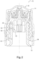
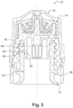
- a device 10 for dispensing liquid in the form of drops comprising a reservoir 12, on which is attached a tip of distribution 14, which can be topped with a protective cap 18, visible on the figure 2 or the figure 3 .
- the reservoir 12 includes a neck 38 for receiving the dispensing tip 14.
- the dispensing tip 14 has an upper dispensing end 20 on which an orifice 16 is provided for dispensing calibrated drops, in this example, by drop-forming means 16. More precisely, still in this example, the dispensing tip 14 is of substantially cylindrical general shape.
- the dispensing tip 14 here comprises a drop-dispensing valve 22, made of elastomer material so as to take, under the pressure of the liquid (when the user presses on the reservoir 12), a liquid passage configuration.
- the dispensing tip 14 further comprises a valve support 24, attached to the reservoir 12, carrying a pin 26 forming a seat against which the valve 22 is pressed and also comprising an air passage duct 28, closed by an air-permeable member 30 preventing the introduction of bacteria into the reservoir 12.
- the dispensing tip 14 also comprises a return element 32, making it possible to return the valve 22 to the liquid blocking configuration.
- the dispensing tip 14 comprises a cover 34 for pressing the valve 22 against the support 24.
- the valve support 24 comprises an internal skirt 40 of substantially tubular general shape, mounted inside the neck 38 of the reservoir 12, as well as an external skirt 41 surrounding the neck 38 of the reservoir 12 and having for example a threaded surface to ensure the screwing of the dispensing tip 14 onto the reservoir 12.
- the threaded surface is on the inner side of the external skirt 41.
- the internal skirt 40 has a lower end of funnel shape, in order to facilitate the introduction of the dispensing tip 14 into the neck 38 of the reservoir 12.
- the neck 38 has a substantially tubular internal surface 42, having a general diameter and which comprises an annular bead 44.
- the annular bead 44 forms a sealing zone 46 with the internal skirt 40 of the dispensing end piece 14.
- the internal skirt 40 comes into contact with the annular bead 44 at a high speed, which can generate plastic shavings, for example in the form of filaments, which risk falling into the reservoir 12 and contaminating the liquid contained in the reservoir 12.
- the internal surface 42 of the neck 38 further comprises a convex annular shape 48, projecting from the internal surface 42 of the neck 38, so as to define a diameter reduced in relation to the general diameter, called the retaining diameter D R of shavings, shown on the figure 1 .
- This chip retention diameter D R is less than the general diameter D of the neck 38 of the reservoir 12, as well as the diameter D E of the neck 38 of the reservoir 12 at the sealing zone 46, called the sealing diameter D E .
- This convex shape 48 creates, by cooperation with the internal skirt 40 of the distribution end piece 14, a chip retention zone 50.
- the neck 38 of the reservoir has a threaded external surface to ensure the screwing of the distribution end piece 14 onto the reservoir 12, by cooperation with the tapped surface of the external skirt 41.
- the internal surface 42 of the neck 38 does not comprise an annular bead but is substantially flat in the sealing zone 46.
- the sealing of the internal surface 42 with the internal skirt 40 is achieved by plane-to-plane contact, in this case cylinder-to-cylinder contact of the two tubular surfaces of the skirt 40 and the internal surface 42.
- the internal surface 42 of the neck 38 also comprises a convex annular shape 48 projecting from the internal surface 42, so as to form, by cooperation with the internal skirt 40 of the distribution tip 14, a chip retention zone 50. In this case, the contact surface is larger, without sharp contact, and the risk of chip creation is thus reduced.
- the sealing of the internal surface 42 with the internal skirt 40 is also ensured by cylinder-to-cylinder contact.
- the internal surface 42 of the neck 38 comprises, downstream and in the direct vicinity of the sealing zone 46, an annular recess 52. Since the chips are created in the sealing zone 46, it is preferable for the contact surface in the sealing zone 46 to be as punctate as possible. Thus, the screwing torque will be reduced and fewer chips will be created.
- the chip retention zone 50 is guaranteed.
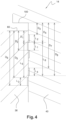
- a "theoretical" length designates a predefined length on the neck of the tank or the dispensing nozzle at the time of design or manufacture of these parts, knowing that, taking into account manufacturing tolerances, once the parts are assembled, the sealing or retention of chips is not necessarily carried out over the entire theoretical length, but only over a portion of this length.
- the neck of the tank has a length L neck min delimited by the upper end of the length of the neck ensuring the sealing L neck sealing and the upper end of the length of the neck ensuring the chip retention zone L neck retention
- the dispensing nozzle has a length L tip max delimited by the lower end of the length of the dispensing nozzle ensuring the sealing L tip sealing and the lower end of the length of the dispensing nozzle ensuring the chip retention zone L tip retention
- the device is sized so that L min neck > L max tip.
- the reservoir 12 is configured so that the internal surface 42 of the neck 38 has a sealing diameter D E greater than the chip retaining diameter D R.
- neck 38 of the reservoir 12 is made, in this example, of low density polyethylene, and the internal skirt 42 of the dispensing tip 14 is made of high density polyethylene.
Landscapes
- Engineering & Computer Science (AREA)
- Mechanical Engineering (AREA)
- Health & Medical Sciences (AREA)
- Ceramic Engineering (AREA)
- Veterinary Medicine (AREA)
- Public Health (AREA)
- General Health & Medical Sciences (AREA)
- Animal Behavior & Ethology (AREA)
- Life Sciences & Earth Sciences (AREA)
- Hematology (AREA)
- Pharmacology & Pharmacy (AREA)
- Vascular Medicine (AREA)
- Heart & Thoracic Surgery (AREA)
- Biomedical Technology (AREA)
- Ophthalmology & Optometry (AREA)
- Closures For Containers (AREA)
- Medical Preparation Storing Or Oral Administration Devices (AREA)
- Details Of Rigid Or Semi-Rigid Containers (AREA)
- Containers Having Bodies Formed In One Piece (AREA)
Claims (9)
- Vorrichtung (10) zur Abgabe von Flüssigkeit, aufweisend ein Abgabeendstück (14) und einen Hals (38) eines Behälters (12) zur Lagerung der Flüssigkeit, wobei das Abgabeendstück (14) durch Verschraubung auf den Hals (38) aufgesetzt ist,- der Hals (38) eine Innenfläche mit einer im Wesentlichen röhrenförmigen allgemeinen Form aufweist,- das Abgabeendstück (14) eine Innenschürze (40) von allgemein im Wesentlichen röhrenförmiger Gestalt aufweist, die im Inneren des Halses (38) des Behälters (12) angebracht ist und mit der Innenfläche (42) des Halses (38) mindestens einen ringförmige Dichtungsbereich (46) definiert, so dass Flüssigkeit, die sich im Behälter (12) befindet, nicht zwischen der Innenschürze (40) des Abgabeendstücks (14) und dem Hals (38) des Behälters (12) hindurchtreten kann,dadurch gekennzeichnet, dass die Innenschürze (40) des Abgabeendstücks (14) zusammen mit der Innenfläche (42) des Halses (38) einen Spanrückhaltebereich (50) definiert, der sich von dem Dichtungsbereich (46) unterscheidet und in Bezug auf den Behälter (12) stromaufwärts angeordnet ist, wobei dieser Spanrückhaltebereich (50) so konfiguriert ist, dass Späne, die während der Montage des Abgabeendstücks (14) auf dem Hals (38) des Behälters (12) an dem Dichtungsbereich (46) gebildet werden, nicht in den Behälter (12) gelangen können,und dadurch, dass die Innenfläche (42) des Halses (38) des Behälters (12), die einen allgemeinen Durchmesser hat, eine konvexe Ringform (48) aufweist, die von der Innenfläche (42) des Halses (38) vorsteht, um einen verringerten Durchmesser (DR) in Bezug auf den allgemeinen Durchmesser (D) des Halses (38) des Behälters (12) zu definieren und dadurch durch Zusammenwirken mit der Innenschürze (40) des Abgabeendstücks (14) den Spanrückhaltebereich (50) zu bilden.
- Vorrichtung (10) nach dem vorhergehenden Anspruch, wobei der verringerte Durchmesser (DR) kleiner ist als der Durchmesser (DE) des Halses (38) des Behälters (12) an dem Dichtungsbereich (46).
- Vorrichtung (10) nach einem der vorhergehenden Ansprüche, die so konfiguriert ist, dass bei der Montage des Abgabeendstücks (14) auf dem Hals (38) des Behälters (12) die Innenschürze (40) des Abgabeendstücks (14) die Innenfläche (42) des Halses (38) des Behälters (12) zunächst im Bereich des Dichtungsbereichs (46) und dann im Bereich des Spanrückhaltebereichs (50) berührt.
- Vorrichtung (10) nach dem vorhergehenden Anspruch, wobei- der Hals (38) des Behälters (12) eine Länge LHals min (L5) aufweist, die durch das obere Ende der Länge des Halses, der die Abdichtung LAbdichtung Hals (L1) gewährleistet, und das obere Ende der Länge des Halses, der den Spanrückhaltebereich (50) gewährleistet LRüekhalte Hals (L3), begrenzt wird.- das Abgabeendstück (14) eine Länge LEndstück max (L6) aufweist, die durch das untere Ende der Länge des Endstücks, die die Abdichtung LAbdichtung Endstück (L2) gewährleistet, und das untere Ende der Länge des Endstücks, das den Spanrückhaltebereich (50) gewährleistet LRüekhalte Endstück (L4), begrenzt wird,und wobei LHals min > LEndstück max, (L5 > L6).
- Vorrichtung (10) nach einem der vorhergehenden Ansprüche, wobei die Innenfläche (42) des Halses (38) des Behälters (12) im Bereich des Dichtungsbereichs (46) im Wesentlichen eben ist, wobei die Abdichtung mit der Innenschürze (40) des Abgabeendstücks (14) durch einen Plan-auf-Plan-Kontakt der Innenschürze (40) des Abgabeendstücks (14) mit der Innenfläche (42) des Halses (38) des Behälters (12) erfolgt.
- Vorrichtung (10) nach einem der Ansprüche 1 bis 2, wobei die Innenfläche (42) des Halses (38) des Behälters (12) im Bereich des Dichtungsbereichs (46) einen ringförmigen Wulst (44) aufweist.
- Vorrichtung (10) nach einem der vorhergehenden Ansprüche, wobei die Innenfläche (42) des Halses (38) des Behälters (12) stromabwärts und in direkter Nachbarschaft zu dem Dichtungsbereich (46) eine ringförmige Aussparung (52) aufweist.
- Vorrichtung (10) nach einem der vorhergehenden Ansprüche, wobei der Hals (38) des Behälters (12) aus Polyethylen niedriger Dichte (LDPE) und die Innenschürze (42) des Abgabeendstücks (14) aus Polyethylen hoher Dichte (HDPE) hergestellt ist.
- Vorrichtung (10) nach einem der vorhergehenden Ansprüche, wobei das Ende der Innenschürze (40) des Abgabeendstücks (14), das sich auf der Seite des Behälters (12) befindet, eine Trichterform aufweist.
Applications Claiming Priority (2)
| Application Number | Priority Date | Filing Date | Title |
|---|---|---|---|
| FR1452902A FR3019530B1 (fr) | 2014-04-02 | 2014-04-02 | Dispositif de distribution de liquide |
| PCT/FR2015/050796 WO2015150673A1 (fr) | 2014-04-02 | 2015-03-27 | Dispositif de distribution de liquide. |
Publications (2)
| Publication Number | Publication Date |
|---|---|
| EP3125838A1 EP3125838A1 (de) | 2017-02-08 |
| EP3125838B1 true EP3125838B1 (de) | 2024-09-18 |
Family
ID=51210547
Family Applications (1)
| Application Number | Title | Priority Date | Filing Date |
|---|---|---|---|
| EP15717570.4A Active EP3125838B1 (de) | 2014-04-02 | 2015-03-27 | Flüssigkeitsabgabevorrichtung |
Country Status (9)
| Country | Link |
|---|---|
| US (2) | US11242181B2 (de) |
| EP (1) | EP3125838B1 (de) |
| JP (1) | JP6482572B2 (de) |
| CN (1) | CN106163933B (de) |
| ES (1) | ES2989350T3 (de) |
| FI (1) | FI3125838T3 (de) |
| FR (1) | FR3019530B1 (de) |
| PL (1) | PL3125838T3 (de) |
| WO (1) | WO2015150673A1 (de) |
Families Citing this family (2)
| Publication number | Priority date | Publication date | Assignee | Title |
|---|---|---|---|---|
| DE102019219884B3 (de) | 2019-12-17 | 2020-08-27 | Heinlein Plastik-Technik Gmbh | Dosier-Verschlusseinrichtung für Flaschen und Kappenverschluss |
| US11591141B2 (en) * | 2020-07-08 | 2023-02-28 | Veraseal Pty Limited | Closures and vessels with closures |
Citations (2)
| Publication number | Priority date | Publication date | Assignee | Title |
|---|---|---|---|---|
| CH597049A5 (en) * | 1975-12-04 | 1978-03-31 | Wiedmer Walter Plastikform | Screw closure for container |
| US20110297703A1 (en) * | 2010-06-07 | 2011-12-08 | Mccormick & Company, Incorporated | Mess free dispensing nozzle and container with suck back feature |
Family Cites Families (23)
| Publication number | Priority date | Publication date | Assignee | Title |
|---|---|---|---|---|
| US2526225A (en) * | 1948-03-04 | 1950-10-17 | Gronemeyer Erich | Container closure |
| US2742195A (en) * | 1952-02-11 | 1956-04-17 | Merck & Co Inc | Dropper closure for containers |
| US3189071A (en) | 1963-05-31 | 1965-06-15 | Cons Thermoplastics Company | Flexible dispensing container assemblies |
| US3494496A (en) * | 1968-01-08 | 1970-02-10 | Jay G Livingstone | Closure cap and container-and-cap assembly |
| US3592349A (en) * | 1969-05-22 | 1971-07-13 | Ethyl Dev Corp | Plastic container and closure |
| CH512228A (de) * | 1970-07-17 | 1971-09-15 | Cws App Ag | Einsatzbehälter für einen Portionenausgeber, insbesondere einen Seifenspender |
| DE8136435U1 (de) * | 1981-12-14 | 1982-04-01 | Heinrich Sieger KG, 5040 Brühl | Mit einer aufsteckbaren Kappe ausgerichteter Stutzen eines Fluessigkeitsbehaelters |
| US4712699A (en) * | 1986-10-02 | 1987-12-15 | Captive Plastics, Inc. | Package employing unique seal |
| US4726484A (en) * | 1986-12-19 | 1988-02-23 | Captive Plastics, Inc. | Package employing unique closure seal and container therefor |
| US5284239A (en) * | 1993-06-04 | 1994-02-08 | The Gillette Company | Bottle with anti-rotation insert |
| US6041953A (en) * | 1995-04-05 | 2000-03-28 | Goodall; Donald Terry | Containers and closures therefor |
| DE19514457C2 (de) * | 1995-04-19 | 1997-04-24 | Stolz Heinrich Gmbh | Verschlußkappe |
| FR2770495B1 (fr) | 1997-11-04 | 1999-12-24 | Transphyto Sa | Dispositif de conditionnement pour liquide a distribuer goutte a goutte |
| DE10160362A1 (de) * | 2001-12-08 | 2003-06-26 | Saint Gobain Oberland Ag | Verschlußkappe |
| FR2845357B1 (fr) | 2002-10-07 | 2005-09-16 | Valois Sas | Dispositif de fixation et distributeur comprenant un tel dispositif de fixation |
| DE20216175U1 (de) * | 2002-10-21 | 2004-04-08 | Georg Menshen Gmbh & Co. Kg | Behälterverschlusskombination |
| DE102004025466B4 (de) * | 2004-05-25 | 2011-07-07 | Georg Menshen GmbH & Co. KG, 57413 | Verschlusskappe |
| GB0616743D0 (en) * | 2006-08-24 | 2006-10-04 | Gizmo Packaging Ltd | Container closure having spout and means for introducing an additive into the contents of the container |
| DE102007007474B3 (de) * | 2007-02-15 | 2008-02-28 | Bernd Hansen | Behältnis |
| FR2934572A1 (fr) | 2008-07-31 | 2010-02-05 | Thea Lab | Embout pour flacon de conditionnement de liquide a distribuer goutte a goutte. |
| FR2952040B1 (fr) | 2009-10-29 | 2011-12-30 | Rexam Pharma La Verpilliere | Dispositif de distribution de liquide sous forme de gouttes |
| KR101104258B1 (ko) * | 2010-05-20 | 2012-01-11 | 최복윤 | 플립 캡 타입 이중격실 튜브용기 및 그 제조방법 |
| FR2980378B1 (fr) | 2011-09-22 | 2016-02-26 | Rexam Healthcare La Verpillier | Dispositif de distribution de liquide sous forme de gouttes |
-
2014
- 2014-04-02 FR FR1452902A patent/FR3019530B1/fr active Active
-
2015
- 2015-03-27 US US15/301,606 patent/US11242181B2/en active Active
- 2015-03-27 PL PL15717570.4T patent/PL3125838T3/pl unknown
- 2015-03-27 FI FIEP15717570.4T patent/FI3125838T3/fi active
- 2015-03-27 ES ES15717570T patent/ES2989350T3/es active Active
- 2015-03-27 CN CN201580014450.9A patent/CN106163933B/zh active Active
- 2015-03-27 EP EP15717570.4A patent/EP3125838B1/de active Active
- 2015-03-27 JP JP2016557120A patent/JP6482572B2/ja active Active
- 2015-03-27 WO PCT/FR2015/050796 patent/WO2015150673A1/fr not_active Ceased
-
2021
- 2021-12-22 US US17/559,705 patent/US11560262B2/en active Active
Patent Citations (2)
| Publication number | Priority date | Publication date | Assignee | Title |
|---|---|---|---|---|
| CH597049A5 (en) * | 1975-12-04 | 1978-03-31 | Wiedmer Walter Plastikform | Screw closure for container |
| US20110297703A1 (en) * | 2010-06-07 | 2011-12-08 | Mccormick & Company, Incorporated | Mess free dispensing nozzle and container with suck back feature |
Also Published As
| Publication number | Publication date |
|---|---|
| ES2989350T3 (es) | 2024-11-26 |
| US11242181B2 (en) | 2022-02-08 |
| JP6482572B2 (ja) | 2019-03-13 |
| US20170029175A1 (en) | 2017-02-02 |
| EP3125838A1 (de) | 2017-02-08 |
| JP2017512720A (ja) | 2017-05-25 |
| CN106163933B (zh) | 2018-11-20 |
| WO2015150673A1 (fr) | 2015-10-08 |
| US11560262B2 (en) | 2023-01-24 |
| FR3019530A1 (fr) | 2015-10-09 |
| FI3125838T3 (fi) | 2024-10-25 |
| FR3019530B1 (fr) | 2018-01-12 |
| CN106163933A (zh) | 2016-11-23 |
| US20220112009A1 (en) | 2022-04-14 |
| PL3125838T3 (pl) | 2024-11-25 |
Similar Documents
| Publication | Publication Date | Title |
|---|---|---|
| EP2635501B1 (de) | Spendekopf für flussiges erzeugnis und ausgabevorrichtung mit solchem spendekopf | |
| EP2694401B1 (de) | Ring für eine vorrichtung zur ausgabe eines flüssigen produkts | |
| EP0807064A1 (de) | Flaschenkörper und abgabeflasche | |
| EP2822870B1 (de) | Abdichtungsvorrichtung sowie behälter mit einer solchen vorrichtung | |
| EP1968870A1 (de) | Ring für aerosol-spenderventil | |
| EP0807065A1 (de) | Abgabeflasche | |
| FR2732742A1 (fr) | Ensemble de clapet d'admission. | |
| EP3125838B1 (de) | Flüssigkeitsabgabevorrichtung | |
| WO2004035225A1 (fr) | Dispositif de fixation et distributeur comprenant un tel dispositif de fixation | |
| EP3256261B1 (de) | Befestigung für eine austragsvorrichtung | |
| EP2934764A1 (de) | Flüssigkeitsspender | |
| EP2178415A2 (de) | Vorrichtung für ein kosmetikprodukt mit einem tank und einem applikator | |
| EP3126265B1 (de) | Anordnung zur abgabe eines aerosols mit verbessertem bereich für den kontakt mit dem hals eines behälters | |
| BE1023035B1 (fr) | Dispositif de distribution de produit pressurisé, valve de distribution doseuse et procédé d'assemblage de ladite valve | |
| EP3388152B1 (de) | Behältnis für ein auszugebendes produkt | |
| WO2012143664A1 (fr) | Dispositif de distribution de produit liquide muni d'un organe de réduction de débit | |
| FR3073373B1 (fr) | Tete d'application et de distribution de produit cosmetique, et dispositif de conditionnement associe | |
| FR2847834A1 (fr) | Dispositif de distribution de produit fluide | |
| EP2921418B1 (de) | Verbessertes rohr, das die abschirmungseigenschaften für das rohrende ausnutzt | |
| EP2890619B1 (de) | Verbesserter rohrkopf mit barriereformendem einsatz mit zentrierung des einsatzes | |
| FR3167137A1 (fr) | Capsule d’obturation d’un récipient, dispositif de conditionnement ou/et de distribution associé | |
| FR2907432A1 (fr) | Conditionnement pour deux composants a melanger et bouchon-dose prevu a cet effet | |
| FR3002122A1 (fr) | Tube, pour produit a consistance liquide, pateuse ou sous forme de gel, notamment pour produits cosmetiques | |
| FR2978429A1 (fr) | Tete de tube munie d'un moyen anti-retour d'air |
Legal Events
| Date | Code | Title | Description |
|---|---|---|---|
| STAA | Information on the status of an ep patent application or granted ep patent |
Free format text: STATUS: THE INTERNATIONAL PUBLICATION HAS BEEN MADE |
|
| PUAI | Public reference made under article 153(3) epc to a published international application that has entered the european phase |
Free format text: ORIGINAL CODE: 0009012 |
|
| STAA | Information on the status of an ep patent application or granted ep patent |
Free format text: STATUS: REQUEST FOR EXAMINATION WAS MADE |
|
| 17P | Request for examination filed |
Effective date: 20161017 |
|
| AK | Designated contracting states |
Kind code of ref document: A1 Designated state(s): AL AT BE BG CH CY CZ DE DK EE ES FI FR GB GR HR HU IE IS IT LI LT LU LV MC MK MT NL NO PL PT RO RS SE SI SK SM TR |
|
| AX | Request for extension of the european patent |
Extension state: BA ME |
|
| DAV | Request for validation of the european patent (deleted) | ||
| DAX | Request for extension of the european patent (deleted) | ||
| STAA | Information on the status of an ep patent application or granted ep patent |
Free format text: STATUS: EXAMINATION IS IN PROGRESS |
|
| 17Q | First examination report despatched |
Effective date: 20210607 |
|
| GRAP | Despatch of communication of intention to grant a patent |
Free format text: ORIGINAL CODE: EPIDOSNIGR1 |
|
| STAA | Information on the status of an ep patent application or granted ep patent |
Free format text: STATUS: GRANT OF PATENT IS INTENDED |
|
| INTG | Intention to grant announced |
Effective date: 20240424 |
|
| GRAS | Grant fee paid |
Free format text: ORIGINAL CODE: EPIDOSNIGR3 |
|
| GRAA | (expected) grant |
Free format text: ORIGINAL CODE: 0009210 |
|
| STAA | Information on the status of an ep patent application or granted ep patent |
Free format text: STATUS: THE PATENT HAS BEEN GRANTED |
|
| AK | Designated contracting states |
Kind code of ref document: B1 Designated state(s): AL AT BE BG CH CY CZ DE DK EE ES FI FR GB GR HR HU IE IS IT LI LT LU LV MC MK MT NL NO PL PT RO RS SE SI SK SM TR |
|
| REG | Reference to a national code |
Ref country code: GB Ref legal event code: FG4D Free format text: NOT ENGLISH |
|
| REG | Reference to a national code |
Ref country code: CH Ref legal event code: EP |
|
| REG | Reference to a national code |
Ref country code: IE Ref legal event code: FG4D Free format text: LANGUAGE OF EP DOCUMENT: FRENCH |
|
| REG | Reference to a national code |
Ref country code: DE Ref legal event code: R096 Ref document number: 602015089920 Country of ref document: DE |
|
| P01 | Opt-out of the competence of the unified patent court (upc) registered |
Free format text: CASE NUMBER: APP_52170/2024 Effective date: 20240917 |
|
| REG | Reference to a national code |
Ref country code: FI Ref legal event code: FGE |
|
| REG | Reference to a national code |
Ref country code: ES Ref legal event code: FG2A Ref document number: 2989350 Country of ref document: ES Kind code of ref document: T3 Effective date: 20241126 |
|
| REG | Reference to a national code |
Ref country code: GR Ref legal event code: EP Ref document number: 20240402617 Country of ref document: GR Effective date: 20241209 |
|
| REG | Reference to a national code |
Ref country code: LT Ref legal event code: MG9D |
|
| PG25 | Lapsed in a contracting state [announced via postgrant information from national office to epo] |
Ref country code: NO Free format text: LAPSE BECAUSE OF FAILURE TO SUBMIT A TRANSLATION OF THE DESCRIPTION OR TO PAY THE FEE WITHIN THE PRESCRIBED TIME-LIMIT Effective date: 20241218 |
|
| PG25 | Lapsed in a contracting state [announced via postgrant information from national office to epo] |
Ref country code: BG Free format text: LAPSE BECAUSE OF FAILURE TO SUBMIT A TRANSLATION OF THE DESCRIPTION OR TO PAY THE FEE WITHIN THE PRESCRIBED TIME-LIMIT Effective date: 20240918 |
|
| PG25 | Lapsed in a contracting state [announced via postgrant information from national office to epo] |
Ref country code: LV Free format text: LAPSE BECAUSE OF FAILURE TO SUBMIT A TRANSLATION OF THE DESCRIPTION OR TO PAY THE FEE WITHIN THE PRESCRIBED TIME-LIMIT Effective date: 20240918 |
|
| PG25 | Lapsed in a contracting state [announced via postgrant information from national office to epo] |
Ref country code: HR Free format text: LAPSE BECAUSE OF FAILURE TO SUBMIT A TRANSLATION OF THE DESCRIPTION OR TO PAY THE FEE WITHIN THE PRESCRIBED TIME-LIMIT Effective date: 20240918 |
|
| REG | Reference to a national code |
Ref country code: NL Ref legal event code: MP Effective date: 20240918 |
|
| PG25 | Lapsed in a contracting state [announced via postgrant information from national office to epo] |
Ref country code: RS Free format text: LAPSE BECAUSE OF FAILURE TO SUBMIT A TRANSLATION OF THE DESCRIPTION OR TO PAY THE FEE WITHIN THE PRESCRIBED TIME-LIMIT Effective date: 20241218 |
|
| PG25 | Lapsed in a contracting state [announced via postgrant information from national office to epo] |
Ref country code: RS Free format text: LAPSE BECAUSE OF FAILURE TO SUBMIT A TRANSLATION OF THE DESCRIPTION OR TO PAY THE FEE WITHIN THE PRESCRIBED TIME-LIMIT Effective date: 20241218 Ref country code: NO Free format text: LAPSE BECAUSE OF FAILURE TO SUBMIT A TRANSLATION OF THE DESCRIPTION OR TO PAY THE FEE WITHIN THE PRESCRIBED TIME-LIMIT Effective date: 20241218 Ref country code: LV Free format text: LAPSE BECAUSE OF FAILURE TO SUBMIT A TRANSLATION OF THE DESCRIPTION OR TO PAY THE FEE WITHIN THE PRESCRIBED TIME-LIMIT Effective date: 20240918 Ref country code: HR Free format text: LAPSE BECAUSE OF FAILURE TO SUBMIT A TRANSLATION OF THE DESCRIPTION OR TO PAY THE FEE WITHIN THE PRESCRIBED TIME-LIMIT Effective date: 20240918 Ref country code: BG Free format text: LAPSE BECAUSE OF FAILURE TO SUBMIT A TRANSLATION OF THE DESCRIPTION OR TO PAY THE FEE WITHIN THE PRESCRIBED TIME-LIMIT Effective date: 20240918 |
|
| REG | Reference to a national code |
Ref country code: AT Ref legal event code: MK05 Ref document number: 1724073 Country of ref document: AT Kind code of ref document: T Effective date: 20240918 |
|
| PG25 | Lapsed in a contracting state [announced via postgrant information from national office to epo] |
Ref country code: NL Free format text: LAPSE BECAUSE OF FAILURE TO SUBMIT A TRANSLATION OF THE DESCRIPTION OR TO PAY THE FEE WITHIN THE PRESCRIBED TIME-LIMIT Effective date: 20240918 |
|
| PG25 | Lapsed in a contracting state [announced via postgrant information from national office to epo] |
Ref country code: IS Free format text: LAPSE BECAUSE OF FAILURE TO SUBMIT A TRANSLATION OF THE DESCRIPTION OR TO PAY THE FEE WITHIN THE PRESCRIBED TIME-LIMIT Effective date: 20250118 Ref country code: PT Free format text: LAPSE BECAUSE OF FAILURE TO SUBMIT A TRANSLATION OF THE DESCRIPTION OR TO PAY THE FEE WITHIN THE PRESCRIBED TIME-LIMIT Effective date: 20250120 |
|
| PG25 | Lapsed in a contracting state [announced via postgrant information from national office to epo] |
Ref country code: RO Free format text: LAPSE BECAUSE OF FAILURE TO SUBMIT A TRANSLATION OF THE DESCRIPTION OR TO PAY THE FEE WITHIN THE PRESCRIBED TIME-LIMIT Effective date: 20240918 Ref country code: SM Free format text: LAPSE BECAUSE OF FAILURE TO SUBMIT A TRANSLATION OF THE DESCRIPTION OR TO PAY THE FEE WITHIN THE PRESCRIBED TIME-LIMIT Effective date: 20240918 |
|
| PG25 | Lapsed in a contracting state [announced via postgrant information from national office to epo] |
Ref country code: AT Free format text: LAPSE BECAUSE OF FAILURE TO SUBMIT A TRANSLATION OF THE DESCRIPTION OR TO PAY THE FEE WITHIN THE PRESCRIBED TIME-LIMIT Effective date: 20240918 Ref country code: EE Free format text: LAPSE BECAUSE OF FAILURE TO SUBMIT A TRANSLATION OF THE DESCRIPTION OR TO PAY THE FEE WITHIN THE PRESCRIBED TIME-LIMIT Effective date: 20240918 |
|
| PGFP | Annual fee paid to national office [announced via postgrant information from national office to epo] |
Ref country code: GR Payment date: 20250320 Year of fee payment: 11 |
|
| PG25 | Lapsed in a contracting state [announced via postgrant information from national office to epo] |
Ref country code: CZ Free format text: LAPSE BECAUSE OF FAILURE TO SUBMIT A TRANSLATION OF THE DESCRIPTION OR TO PAY THE FEE WITHIN THE PRESCRIBED TIME-LIMIT Effective date: 20240918 |
|
| PGFP | Annual fee paid to national office [announced via postgrant information from national office to epo] |
Ref country code: PL Payment date: 20250218 Year of fee payment: 11 |
|
| PG25 | Lapsed in a contracting state [announced via postgrant information from national office to epo] |
Ref country code: SK Free format text: LAPSE BECAUSE OF FAILURE TO SUBMIT A TRANSLATION OF THE DESCRIPTION OR TO PAY THE FEE WITHIN THE PRESCRIBED TIME-LIMIT Effective date: 20240918 |
|
| PGFP | Annual fee paid to national office [announced via postgrant information from national office to epo] |
Ref country code: IT Payment date: 20250325 Year of fee payment: 11 |
|
| REG | Reference to a national code |
Ref country code: DE Ref legal event code: R097 Ref document number: 602015089920 Country of ref document: DE |
|
| PG25 | Lapsed in a contracting state [announced via postgrant information from national office to epo] |
Ref country code: DK Free format text: LAPSE BECAUSE OF FAILURE TO SUBMIT A TRANSLATION OF THE DESCRIPTION OR TO PAY THE FEE WITHIN THE PRESCRIBED TIME-LIMIT Effective date: 20240918 |
|
| PGFP | Annual fee paid to national office [announced via postgrant information from national office to epo] |
Ref country code: ES Payment date: 20250429 Year of fee payment: 11 |
|
| PGFP | Annual fee paid to national office [announced via postgrant information from national office to epo] |
Ref country code: CH Payment date: 20250401 Year of fee payment: 11 |
|
| PLBE | No opposition filed within time limit |
Free format text: ORIGINAL CODE: 0009261 |
|
| STAA | Information on the status of an ep patent application or granted ep patent |
Free format text: STATUS: NO OPPOSITION FILED WITHIN TIME LIMIT |
|
| 26N | No opposition filed |
Effective date: 20250619 |
|
| PG25 | Lapsed in a contracting state [announced via postgrant information from national office to epo] |
Ref country code: SE Free format text: LAPSE BECAUSE OF FAILURE TO SUBMIT A TRANSLATION OF THE DESCRIPTION OR TO PAY THE FEE WITHIN THE PRESCRIBED TIME-LIMIT Effective date: 20240918 |
|
| PG25 | Lapsed in a contracting state [announced via postgrant information from national office to epo] |
Ref country code: MC Free format text: LAPSE BECAUSE OF FAILURE TO SUBMIT A TRANSLATION OF THE DESCRIPTION OR TO PAY THE FEE WITHIN THE PRESCRIBED TIME-LIMIT Effective date: 20240918 |
|
| PG25 | Lapsed in a contracting state [announced via postgrant information from national office to epo] |
Ref country code: LU Free format text: LAPSE BECAUSE OF NON-PAYMENT OF DUE FEES Effective date: 20250327 |
|
| REG | Reference to a national code |
Ref country code: CH Ref legal event code: U11 Free format text: ST27 STATUS EVENT CODE: U-0-0-U10-U11 (AS PROVIDED BY THE NATIONAL OFFICE) Effective date: 20260401 |
|
| PGFP | Annual fee paid to national office [announced via postgrant information from national office to epo] |
Ref country code: GB Payment date: 20260324 Year of fee payment: 12 |
|
| PGFP | Annual fee paid to national office [announced via postgrant information from national office to epo] |
Ref country code: DE Payment date: 20260320 Year of fee payment: 12 Ref country code: IE Payment date: 20260323 Year of fee payment: 12 |
|
| PGFP | Annual fee paid to national office [announced via postgrant information from national office to epo] |
Ref country code: BE Payment date: 20260323 Year of fee payment: 12 Ref country code: FI Payment date: 20260320 Year of fee payment: 12 |
|
| PGFP | Annual fee paid to national office [announced via postgrant information from national office to epo] |
Ref country code: FR Payment date: 20260325 Year of fee payment: 12 |
|
| PGFP | Annual fee paid to national office [announced via postgrant information from national office to epo] |
Ref country code: TR Payment date: 20260326 Year of fee payment: 12 |