EP3125259A1 - Magnetisches element - Google Patents
Magnetisches element Download PDFInfo
- Publication number
- EP3125259A1 EP3125259A1 EP15768781.5A EP15768781A EP3125259A1 EP 3125259 A1 EP3125259 A1 EP 3125259A1 EP 15768781 A EP15768781 A EP 15768781A EP 3125259 A1 EP3125259 A1 EP 3125259A1
- Authority
- EP
- European Patent Office
- Prior art keywords
- magnetic body
- magnetic
- compression molded
- coil
- injection molded
- Prior art date
- Legal status (The legal status is an assumption and is not a legal conclusion. Google has not performed a legal analysis and makes no representation as to the accuracy of the status listed.)
- Granted
Links
- 230000006835 compression Effects 0.000 claims abstract description 78
- 238000007906 compression Methods 0.000 claims abstract description 78
- 238000002347 injection Methods 0.000 claims abstract description 61
- 239000007924 injection Substances 0.000 claims abstract description 61
- XEEYBQQBJWHFJM-UHFFFAOYSA-N Iron Chemical compound [Fe] XEEYBQQBJWHFJM-UHFFFAOYSA-N 0.000 claims abstract description 27
- 229910052742 iron Inorganic materials 0.000 claims abstract description 13
- 230000017525 heat dissipation Effects 0.000 claims abstract description 11
- 230000004907 flux Effects 0.000 claims abstract description 6
- 239000011800 void material Substances 0.000 claims description 5
- 230000020169 heat generation Effects 0.000 abstract description 10
- 239000000843 powder Substances 0.000 description 48
- 239000000463 material Substances 0.000 description 34
- 238000000034 method Methods 0.000 description 16
- 239000000696 magnetic material Substances 0.000 description 15
- 238000001746 injection moulding Methods 0.000 description 13
- 229910000859 α-Fe Inorganic materials 0.000 description 12
- 239000000956 alloy Substances 0.000 description 11
- 229910045601 alloy Inorganic materials 0.000 description 11
- 239000004734 Polyphenylene sulfide Substances 0.000 description 10
- 229920000069 polyphenylene sulfide Polymers 0.000 description 10
- 229920005989 resin Polymers 0.000 description 10
- 239000011347 resin Substances 0.000 description 10
- 238000004519 manufacturing process Methods 0.000 description 9
- 229920005992 thermoplastic resin Polymers 0.000 description 9
- 238000000465 moulding Methods 0.000 description 8
- 239000005300 metallic glass Substances 0.000 description 7
- 238000004804 winding Methods 0.000 description 7
- 239000002131 composite material Substances 0.000 description 6
- 238000001816 cooling Methods 0.000 description 6
- 238000009413 insulation Methods 0.000 description 6
- 239000006247 magnetic powder Substances 0.000 description 6
- 238000002156 mixing Methods 0.000 description 6
- 238000000748 compression moulding Methods 0.000 description 5
- 239000010408 film Substances 0.000 description 5
- 239000000203 mixture Substances 0.000 description 5
- 239000002245 particle Substances 0.000 description 5
- RYGMFSIKBFXOCR-UHFFFAOYSA-N Copper Chemical compound [Cu] RYGMFSIKBFXOCR-UHFFFAOYSA-N 0.000 description 4
- PXHVJJICTQNCMI-UHFFFAOYSA-N Nickel Chemical compound [Ni] PXHVJJICTQNCMI-UHFFFAOYSA-N 0.000 description 4
- 229910052802 copper Inorganic materials 0.000 description 4
- 239000010949 copper Substances 0.000 description 4
- 239000008358 core component Substances 0.000 description 4
- 238000010304 firing Methods 0.000 description 4
- 230000035699 permeability Effects 0.000 description 4
- -1 polyethylene Polymers 0.000 description 4
- 239000004642 Polyimide Substances 0.000 description 3
- 229910000808 amorphous metal alloy Inorganic materials 0.000 description 3
- 230000000052 comparative effect Effects 0.000 description 3
- 230000002349 favourable effect Effects 0.000 description 3
- 229920001721 polyimide Polymers 0.000 description 3
- 239000002994 raw material Substances 0.000 description 3
- 229910000702 sendust Inorganic materials 0.000 description 3
- 229910052596 spinel Inorganic materials 0.000 description 3
- 239000011029 spinel Substances 0.000 description 3
- 229920001187 thermosetting polymer Polymers 0.000 description 3
- 229910000531 Co alloy Inorganic materials 0.000 description 2
- 239000004696 Poly ether ether ketone Substances 0.000 description 2
- 239000004962 Polyamide-imide Substances 0.000 description 2
- MCMNRKCIXSYSNV-UHFFFAOYSA-N Zirconium dioxide Chemical compound O=[Zr]=O MCMNRKCIXSYSNV-UHFFFAOYSA-N 0.000 description 2
- 239000000853 adhesive Substances 0.000 description 2
- 238000004458 analytical method Methods 0.000 description 2
- 238000000576 coating method Methods 0.000 description 2
- 210000003298 dental enamel Anatomy 0.000 description 2
- 239000011888 foil Substances 0.000 description 2
- 239000002223 garnet Substances 0.000 description 2
- 229910052751 metal Inorganic materials 0.000 description 2
- 239000002184 metal Substances 0.000 description 2
- 229910052759 nickel Inorganic materials 0.000 description 2
- 229920002312 polyamide-imide Polymers 0.000 description 2
- 229920002530 polyetherether ketone Polymers 0.000 description 2
- 239000011342 resin composition Substances 0.000 description 2
- 239000000758 substrate Substances 0.000 description 2
- 239000010409 thin film Substances 0.000 description 2
- 229910020598 Co Fe Inorganic materials 0.000 description 1
- 229910002519 Co-Fe Inorganic materials 0.000 description 1
- 239000004593 Epoxy Substances 0.000 description 1
- JOYRKODLDBILNP-UHFFFAOYSA-N Ethyl urethane Chemical compound CCOC(N)=O JOYRKODLDBILNP-UHFFFAOYSA-N 0.000 description 1
- CWYNVVGOOAEACU-UHFFFAOYSA-N Fe2+ Chemical compound [Fe+2] CWYNVVGOOAEACU-UHFFFAOYSA-N 0.000 description 1
- 229920000106 Liquid crystal polymer Polymers 0.000 description 1
- 239000004977 Liquid-crystal polymers (LCPs) Substances 0.000 description 1
- 229910001289 Manganese-zinc ferrite Inorganic materials 0.000 description 1
- 229910003271 Ni-Fe Inorganic materials 0.000 description 1
- 229910001053 Nickel-zinc ferrite Inorganic materials 0.000 description 1
- 229920003171 Poly (ethylene oxide) Polymers 0.000 description 1
- 229930182556 Polyacetal Natural products 0.000 description 1
- 239000004952 Polyamide Substances 0.000 description 1
- 239000004695 Polyether sulfone Substances 0.000 description 1
- 239000004697 Polyetherimide Substances 0.000 description 1
- 239000004698 Polyethylene Substances 0.000 description 1
- 239000004721 Polyphenylene oxide Substances 0.000 description 1
- 239000004954 Polyphthalamide Substances 0.000 description 1
- 239000004743 Polypropylene Substances 0.000 description 1
- 239000004372 Polyvinyl alcohol Substances 0.000 description 1
- 229910002796 Si–Al Inorganic materials 0.000 description 1
- 229910008423 Si—B Inorganic materials 0.000 description 1
- 229910008458 Si—Cr Inorganic materials 0.000 description 1
- 229910001308 Zinc ferrite Inorganic materials 0.000 description 1
- JIYIUPFAJUGHNL-UHFFFAOYSA-N [O--].[O--].[O--].[O--].[O--].[O--].[O--].[O--].[O--].[O--].[O--].[O--].[O--].[O--].[O--].[O--].[O--].[O--].[O--].[O--].[Mn++].[Mn++].[Mn++].[Fe+3].[Fe+3].[Fe+3].[Fe+3].[Fe+3].[Fe+3].[Fe+3].[Fe+3].[Fe+3].[Fe+3].[Zn++].[Zn++] Chemical compound [O--].[O--].[O--].[O--].[O--].[O--].[O--].[O--].[O--].[O--].[O--].[O--].[O--].[O--].[O--].[O--].[O--].[O--].[O--].[O--].[Mn++].[Mn++].[Mn++].[Fe+3].[Fe+3].[Fe+3].[Fe+3].[Fe+3].[Fe+3].[Fe+3].[Fe+3].[Fe+3].[Fe+3].[Zn++].[Zn++] JIYIUPFAJUGHNL-UHFFFAOYSA-N 0.000 description 1
- PNEYBMLMFCGWSK-UHFFFAOYSA-N aluminium oxide Inorganic materials [O-2].[O-2].[O-2].[Al+3].[Al+3] PNEYBMLMFCGWSK-UHFFFAOYSA-N 0.000 description 1
- 230000004323 axial length Effects 0.000 description 1
- 239000011230 binding agent Substances 0.000 description 1
- 239000011248 coating agent Substances 0.000 description 1
- 239000000306 component Substances 0.000 description 1
- 230000010485 coping Effects 0.000 description 1
- TVZPLCNGKSPOJA-UHFFFAOYSA-N copper zinc Chemical compound [Cu].[Zn] TVZPLCNGKSPOJA-UHFFFAOYSA-N 0.000 description 1
- 229910052593 corundum Inorganic materials 0.000 description 1
- 238000002425 crystallisation Methods 0.000 description 1
- 230000008025 crystallization Effects 0.000 description 1
- 238000005520 cutting process Methods 0.000 description 1
- 230000003111 delayed effect Effects 0.000 description 1
- 230000000694 effects Effects 0.000 description 1
- 238000007772 electroless plating Methods 0.000 description 1
- 230000005672 electromagnetic field Effects 0.000 description 1
- 239000003822 epoxy resin Substances 0.000 description 1
- 239000011521 glass Substances 0.000 description 1
- 239000012774 insulation material Substances 0.000 description 1
- 229910001337 iron nitride Inorganic materials 0.000 description 1
- MTRJKZUDDJZTLA-UHFFFAOYSA-N iron yttrium Chemical compound [Fe].[Y] MTRJKZUDDJZTLA-UHFFFAOYSA-N 0.000 description 1
- SZVJSHCCFOBDDC-UHFFFAOYSA-N iron(II,III) oxide Inorganic materials O=[Fe]O[Fe]O[Fe]=O SZVJSHCCFOBDDC-UHFFFAOYSA-N 0.000 description 1
- CPLXHLVBOLITMK-UHFFFAOYSA-N magnesium oxide Inorganic materials [Mg]=O CPLXHLVBOLITMK-UHFFFAOYSA-N 0.000 description 1
- 238000002844 melting Methods 0.000 description 1
- 230000008018 melting Effects 0.000 description 1
- 150000002739 metals Chemical class 0.000 description 1
- 239000013080 microcrystalline material Substances 0.000 description 1
- AJCDFVKYMIUXCR-UHFFFAOYSA-N oxobarium;oxo(oxoferriooxy)iron Chemical compound [Ba]=O.O=[Fe]O[Fe]=O.O=[Fe]O[Fe]=O.O=[Fe]O[Fe]=O.O=[Fe]O[Fe]=O.O=[Fe]O[Fe]=O.O=[Fe]O[Fe]=O AJCDFVKYMIUXCR-UHFFFAOYSA-N 0.000 description 1
- 230000002093 peripheral effect Effects 0.000 description 1
- 229910000889 permalloy Inorganic materials 0.000 description 1
- 229920003055 poly(ester-imide) Polymers 0.000 description 1
- 229920002492 poly(sulfone) Polymers 0.000 description 1
- 229920002647 polyamide Polymers 0.000 description 1
- 229920001707 polybutylene terephthalate Polymers 0.000 description 1
- 239000004417 polycarbonate Substances 0.000 description 1
- 229920000515 polycarbonate Polymers 0.000 description 1
- 229920000647 polyepoxide Polymers 0.000 description 1
- 229920000728 polyester Polymers 0.000 description 1
- 229920006393 polyether sulfone Polymers 0.000 description 1
- 229920001601 polyetherimide Polymers 0.000 description 1
- 229920000573 polyethylene Polymers 0.000 description 1
- 229920000139 polyethylene terephthalate Polymers 0.000 description 1
- 239000005020 polyethylene terephthalate Substances 0.000 description 1
- 229920000098 polyolefin Polymers 0.000 description 1
- 229920006324 polyoxymethylene Polymers 0.000 description 1
- 229920006380 polyphenylene oxide Polymers 0.000 description 1
- 229920006375 polyphtalamide Polymers 0.000 description 1
- 229920001155 polypropylene Polymers 0.000 description 1
- 229920002451 polyvinyl alcohol Polymers 0.000 description 1
- 230000005855 radiation Effects 0.000 description 1
- 238000003980 solgel method Methods 0.000 description 1
- 238000004544 sputter deposition Methods 0.000 description 1
- 229910052712 strontium Inorganic materials 0.000 description 1
- CIOAGBVUUVVLOB-UHFFFAOYSA-N strontium atom Chemical compound [Sr] CIOAGBVUUVVLOB-UHFFFAOYSA-N 0.000 description 1
- 239000000126 substance Substances 0.000 description 1
- 238000002076 thermal analysis method Methods 0.000 description 1
- 238000003466 welding Methods 0.000 description 1
- 229910001845 yogo sapphire Inorganic materials 0.000 description 1
- RUDFQVOCFDJEEF-UHFFFAOYSA-N yttrium(III) oxide Inorganic materials [O-2].[O-2].[O-2].[Y+3].[Y+3] RUDFQVOCFDJEEF-UHFFFAOYSA-N 0.000 description 1
Images


Classifications
-
- H—ELECTRICITY
- H01—ELECTRIC ELEMENTS
- H01F—MAGNETS; INDUCTANCES; TRANSFORMERS; SELECTION OF MATERIALS FOR THEIR MAGNETIC PROPERTIES
- H01F27/00—Details of transformers or inductances, in general
- H01F27/24—Magnetic cores
- H01F27/255—Magnetic cores made from particles
-
- H—ELECTRICITY
- H01—ELECTRIC ELEMENTS
- H01F—MAGNETS; INDUCTANCES; TRANSFORMERS; SELECTION OF MATERIALS FOR THEIR MAGNETIC PROPERTIES
- H01F27/00—Details of transformers or inductances, in general
- H01F27/28—Coils; Windings; Conductive connections
- H01F27/2823—Wires
-
- H—ELECTRICITY
- H01—ELECTRIC ELEMENTS
- H01F—MAGNETS; INDUCTANCES; TRANSFORMERS; SELECTION OF MATERIALS FOR THEIR MAGNETIC PROPERTIES
- H01F3/00—Cores, Yokes, or armatures
- H01F3/10—Composite arrangements of magnetic circuits
-
- H—ELECTRICITY
- H01—ELECTRIC ELEMENTS
- H01F—MAGNETS; INDUCTANCES; TRANSFORMERS; SELECTION OF MATERIALS FOR THEIR MAGNETIC PROPERTIES
- H01F37/00—Fixed inductances not covered by group H01F17/00
-
- H—ELECTRICITY
- H01—ELECTRIC ELEMENTS
- H01F—MAGNETS; INDUCTANCES; TRANSFORMERS; SELECTION OF MATERIALS FOR THEIR MAGNETIC PROPERTIES
- H01F1/00—Magnets or magnetic bodies characterised by the magnetic materials therefor; Selection of materials for their magnetic properties
- H01F1/01—Magnets or magnetic bodies characterised by the magnetic materials therefor; Selection of materials for their magnetic properties of inorganic materials
- H01F1/03—Magnets or magnetic bodies characterised by the magnetic materials therefor; Selection of materials for their magnetic properties of inorganic materials characterised by their coercivity
- H01F1/12—Magnets or magnetic bodies characterised by the magnetic materials therefor; Selection of materials for their magnetic properties of inorganic materials characterised by their coercivity of soft-magnetic materials
- H01F1/14—Magnets or magnetic bodies characterised by the magnetic materials therefor; Selection of materials for their magnetic properties of inorganic materials characterised by their coercivity of soft-magnetic materials metals or alloys
- H01F1/147—Alloys characterised by their composition
- H01F1/14708—Fe-Ni based alloys
- H01F1/14733—Fe-Ni based alloys in the form of particles
-
- H—ELECTRICITY
- H01—ELECTRIC ELEMENTS
- H01F—MAGNETS; INDUCTANCES; TRANSFORMERS; SELECTION OF MATERIALS FOR THEIR MAGNETIC PROPERTIES
- H01F1/00—Magnets or magnetic bodies characterised by the magnetic materials therefor; Selection of materials for their magnetic properties
- H01F1/01—Magnets or magnetic bodies characterised by the magnetic materials therefor; Selection of materials for their magnetic properties of inorganic materials
- H01F1/03—Magnets or magnetic bodies characterised by the magnetic materials therefor; Selection of materials for their magnetic properties of inorganic materials characterised by their coercivity
- H01F1/12—Magnets or magnetic bodies characterised by the magnetic materials therefor; Selection of materials for their magnetic properties of inorganic materials characterised by their coercivity of soft-magnetic materials
- H01F1/14—Magnets or magnetic bodies characterised by the magnetic materials therefor; Selection of materials for their magnetic properties of inorganic materials characterised by their coercivity of soft-magnetic materials metals or alloys
- H01F1/147—Alloys characterised by their composition
- H01F1/14766—Fe-Si based alloys
- H01F1/14791—Fe-Si-Al based alloys, e.g. Sendust
-
- H—ELECTRICITY
- H01—ELECTRIC ELEMENTS
- H01F—MAGNETS; INDUCTANCES; TRANSFORMERS; SELECTION OF MATERIALS FOR THEIR MAGNETIC PROPERTIES
- H01F17/00—Fixed inductances of the signal type
- H01F17/04—Fixed inductances of the signal type with magnetic core
- H01F17/043—Fixed inductances of the signal type with magnetic core with two, usually identical or nearly identical parts enclosing completely the coil (pot cores)
-
- H—ELECTRICITY
- H01—ELECTRIC ELEMENTS
- H01F—MAGNETS; INDUCTANCES; TRANSFORMERS; SELECTION OF MATERIALS FOR THEIR MAGNETIC PROPERTIES
- H01F3/00—Cores, Yokes, or armatures
- H01F3/10—Composite arrangements of magnetic circuits
- H01F2003/106—Magnetic circuits using combinations of different magnetic materials
Definitions
- the present invention relates to a magnetic element consisting of a coil wound around the circumference of a magnetic body.
- the present invention relates particularly to a magnetic element for use in electrical or electronic equipment as an inductor, a transformer, an antenna (bar antenna), a choke coil, a filter, a sensor, and the like.
- the present applicant proposed a method of producing the core component having a predetermined magnetic characteristic by performing injection molding.
- the core component is composed of the compression molded magnetic body or the compressed powder magnet molded body containing a binding agent having a melting point lower than the injection molding temperature thereof.
- the magnetic powder contained in the resin composition to be injection-molded is coated with the insulation material and thereafter the compression molded magnetic body or the compressed powder magnet molded body is insert-molded in the above-described resin composition.
- the present applicant filed a patent application for the composite magnetic core composed of the combined body of the compression molded magnetic body obtained by compression molding magnetic powder and the injection molded magnetic body obtained by injection molding the magnetic powder, whose surface has been electrically insulated, to which binding resin is added.
- the injection molded magnetic body is used as the housing in which the compression molded magnetic body is disposed (patent document 2).
- the size of the magnetic element to be used becomes larger.
- the magnetic element has an unignorable problem that the magnetic element to be used for a large current generates heat owing to iron loss in addition to the copper loss-caused heat generation which has been a problem.
- the present invention has been made to deal with the above-described problems. Therefore it is an object of the present invention to provide a magnetic element in which iron loss-caused heat generation is restrained and which can be produced with a high productivity.
- the magnetic element of the present invention has a coil and a magnetic body which allows a magnetic flux generated by the coil to pass therethrough.
- a compression molded magnetic body is disposed at a portion generating iron loss-caused heat to a high extent or a portion inferior in heat dissipation performance.
- An injection molded magnetic body is disposed at a portion other than the portion where the compression molded magnetic body is disposed, for example, a portion to be large-sized or a portion to be formed in a complicated configuration.
- the compression molded magnetic body and the injection molded magnetic body are combined with each other.
- the coil is disposed inside the magnetic body.
- the compression molded magnetic body is disposed at an inside diameter side of the coil, whereas the injection molded magnetic body is disposed at an outside diameter side of the coil.
- the compression molded magnetic body is exposed to a surface of the magnetic body composed of the compression molded and injection molded bodies.
- the injection molded magnetic body is a combined body formed by combining two halves, of the injection molded magnetic body, obtained by bisection made in an axial direction of the coil with each other.
- the compression molded magnetic body has a void portion inside the magnetic body composed of the compression molded and injection molded bodies.
- the compression molded magnetic body by disposing the compression molded magnetic body at the portion generating the iron loss-caused heat to a high extent or the portion inferior in heat dissipation performance, it is possible to restrain the magnetic element from generating heat and hence protect the magnetic body and the insulation film of the coil.
- the magnetic element of the present invention allows the production equipment cost to decrease, the productivity thereof to be improved, the production cost to decrease, and the degree of freedom of configuration to be improved.
- a magnetic element using a ferrite material obtained by a compression molding method which currently prevails in molding methods is superior in its magnetic permeability and provides a high inductance value, but is inferior in its frequency characteristic and current superimposition characteristic.
- a magnetic element using an injection molded magnetic material containing an amorphous material is superior in its frequency characteristic and current superimposition characteristic, but is low in its magnetic permeability.
- the magnetic element for a large current has an unignorable problem that it generates heat owing to copper loss and also owing to iron loss.
- the present inventors have invented a magnetic element having a structure in which a compression molded magnetic body excellent in its heat conductance is disposed at a portion liable to generate heat or a portion where it is difficult to dissipate heat.
- a large magnetic body large or a magnetic body having a complicated configuration is formed by molding an injection molding magnetic material.
- the magnetic element of the present invention can be preferably used as a pot-shaped magnetic element having a coil disposed inside the magnetic body.
- the pot-shaped magnetic element has an advantage that it is provided with a magnetic path in such a way as to cover the coil, the leakage amount of a magnetic flux is allowed to be small.
- the pot-shaped magnetic element has another advantage that it is possible to make the configuration of the magnetic body small. But the pot-shaped magnetic element has a problem that at the inside diameter side of the coil, it is structurally difficult to dissipate heat generated in the magnetic body and the coil to the outside.
- the compression molded magnetic body is disposed at the inside diameter side of the coil.
- the compression molded magnetic body is so disposed that the compression molded magnetic body is exposed to the surface of the magnetic body composed of the compression molded and injection molded magnetic bodies.
- the present inventors have succeeded in accelerating the heat conduction performance at the inside diameter side of the coil where it is difficult to dissipate heat.
- the magnetic raw material examples include a pure iron-based soft magnetic material such as iron powder and iron nitride powder; a ferrous alloy-based soft magnetic material such as Fe-Si-Al alloy (sendust) powder, super sendust powder, Ni-Fe alloy (permalloy) powder, Co-Fe alloy powder, and Fe-Si-B-based alloy powder; a ferrite-based magnetic material; an amorphous magnetic material; and a microcrystalline material.
- a pure iron-based soft magnetic material such as iron powder and iron nitride powder
- a ferrous alloy-based soft magnetic material such as Fe-Si-Al alloy (sendust) powder, super sendust powder, Ni-Fe alloy (permalloy) powder, Co-Fe alloy powder, and Fe-Si-B-based alloy powder
- a ferrite-based magnetic material an amorphous magnetic material
- a microcrystalline material examples include a microcrystalline material.
- the ferrite-based magnetic material examples include spinel ferrite having a spinel crystalline structure such as manganese zinc ferrite, nickel-zinc ferrite, copper zinc ferrite, and magnetite; hexagonal ferrite such as barium ferrite and strontium ferrite; and garnet ferrite such as yttrium iron garnet.
- the spinel ferrite which is a soft magnetic ferrite is preferable because it has a high magnetic permeability and a small eddy current loss in a high frequency domain.
- amorphous magnetic material examples include iron-based alloys, cobalt-based alloys, nickel-based alloys, and mixtures of these amorphous alloys.
- oxides forming an insulation film on the surfaces of particles of soft magnetic metal powder to be used as the above-described raw materials for the compression molded magnetic body include oxides of insulation metals or semimetals such as Al 2 O 3 , Y 2 O 3 , MgO, and ZrO 2 ; glass; and mixtures of these substances.
- the insulation film As methods of forming the insulation film, it is possible to use a powder coating method such as mechanofusion, a wet thin film forming method such as electroless plating and a sol-gel method, and a dry thin film forming method such as sputtering.
- a powder coating method such as mechanofusion
- a wet thin film forming method such as electroless plating and a sol-gel method
- a dry thin film forming method such as sputtering.
- the compression molded magnetic body can be produced by pressure-molding the above-described material powder having the insulation film formed on the surfaces of particles thereof or pressure-molding powder composed of the above-described material powder and thermosetting resin such as epoxy resin added thereto to obtain a compressed powder compact and thereafter by firing the compressed powder compact.
- the average diameter of the particles of the material powder is favorably 1 to 150 ⁇ m and more favorably 5 to 100 ⁇ m.
- the compressibility (a measure showing the hardenability of powder) of the material powder is low in a pressure-molding operation. Consequently the strength of the material for the compression molded magnetic body becomes outstandingly low after the compressed powder compact is fired.
- the material powder has a large iron loss in a high frequency domain. Consequently the material powder has a low magnetic characteristic (frequency characteristic).
- the mixing ratio of the material powder Supposing that the total of the amount of the material powder and that of the thermosetting resin is 100 percentages by mass, it is preferable to set the mixing ratio of the material powder to 96 to 100 percentages by mass. When the mixing ratio of the material powder is less than 96 percentages by mass, the mixing ratio thereof is low. Thus the material powder has a low magnetic flux density and a low magnetic permeability.
- a compression molding method it is possible to use a method of filling the material powder into a die and press-molding the material powder at a predetermined pressure to obtain the compressed powder compact.
- a fired object is obtained by firing the compressed powder compact.
- a firing temperature lower than the crystallization start temperature of the amorphous alloy.
- the powder to which the thermosetting resin has been added it is necessary to set the firing temperature to a temperature range in which the resin hardens.
- the injection molded magnetic body which can be used in the present invention is obtained by adding a binding resin to the material powder for the compression molded magnetic body and by injection-molding the mixture of the binding resin and the material powder.
- the amorphous metal powder allows the injection molding to be easily performed, the configuration of the injection molded magnetic body formed by the injection molding to be easily maintained, and the composite magnetic core to have an excellent magnetic characteristic.
- the amorphous metal powder it is possible to use the above-described iron-based alloys, cobalt-based alloys, nickel-based alloys, and mixtures of these amorphous alloys.
- the above-described insulation film is formed on the surfaces of these amorphous metal powders.
- thermoplastic resin which can be injection-molded.
- the thermoplastic resin include polyolefin such as polyethylene and polypropylene, polyvinyl alcohol, polyethylene oxide, polyphenylene sulfide (PPS), liquid crystal polymer, polyether ether ketone (PEEK), polyimide, polyetherimide, polyacetal, polyether sulfone, polysulfone, polycarbonate, polyethylene terephthalate, polybutylene terephthalate, polyphenylene oxide, polyphthalamide, polyamide, and mixtures of these thermoplastic resins.
- polyolefin such as polyethylene and polypropylene, polyvinyl alcohol, polyethylene oxide, polyphenylene sulfide (PPS), liquid crystal polymer, polyether ether ketone (PEEK), polyimide, polyetherimide, polyacetal, polyether sulfone, polysulfone, polycarbonate, polyethylene terephthalate, polybutylene terephthalate, polyphenylene
- the polyphenylene sulfide (PPS) is more favorable than the other thermoplastic resins because the polyphenylene sulfide (PPS) is excellent in its flowability in an injection molding operation when it is mixed with the amorphous metal powder, is capable of coating the surface of the resulting injection-molded body with a layer thereof, and is excellent in its heat resistance.
- the mixing ratio of the material powder it is preferable to set the mixing ratio of the material powder to 80 to 95 percentages by mass. In a case where the mixing ratio of the material powder is less than 80 percentages by mass, the material powder is incapable of obtaining the predetermined magnetic characteristic. In a case where the mixing ratio of the material powder exceeds 95 percentages by mass, the material powder causes the injection moldability to be inferior.
- the injection molding method it is possible to use a method of injecting the material powder into a die consisting of a movable half thereof butted with a fixed half thereof.
- the injection-molding condition it is preferable to set the temperature of the resin to 290 to 350°C and that of the die to 100 to 150°C in the case of the polyphenylene sulfide (PPS), although the injection-molding condition is different according to the kind of the thermoplastic resin.
- PPS polyphenylene sulfide
- the compression molded and injection molded magnetic bodies are separately produced by the above-described methods and combined with each other.
- the former and the latter are so configured that they can be assembled easily and are suitable for compression molding and injection molding respectively.
- a columnar configuration to be disposed at the inside diameter side of the coil is formed as the compression molded magnetic body by performing compression molding, whereas the outside diameter side of the coil is formed as the injection molded magnetic body by performing injection molding.
- the columnar magnetic body is obtained.
- the injection molded magnetic body is formed by insert molding. In this manner, the columnar magnetic body can be produced.
- the injection molded magnetic body is divided into two halves in the axial direction thereof in which the coil is inserted thereinto. Any bisecting method can be used so long as the coil is inserted into the injection molded magnetic body. It is preferable to axially divide the injection molded magnetic body into two halves. By dividing the injection molded magnetic body into the two halves, it is possible to decrease the number of dies. In a case where an adhesive agent is used to combine the two halves with each other, it is preferable to use a solventless type epoxy-based adhesive agent which allows the two halves to adhere to each other closely.
- the material for the compression molded magnetic body is amorphous and that the material for the injection molded magnetic body is amorphous metal powder and the thermoplastic resin. It is more favorable to use Fe-Si-Cr-based amorphous alloy as the amorphous metal and the polyphenylene sulfide (PPS) as the thermoplastic resin.
- PPS polyphenylene sulfide
- the magnetic element of the present invention is composed of the compression molded magnetic body and a winding wound around the circumference thereof to form the coil having the function of an inductor.
- the magnetic element is incorporated in circuits of electrical and electronic equipment.
- a copper enamel wire can be used as the winding. It is possible to use a urethane wire (UEW), a formal wire (PVF), polyester wire (PEW), a polyester imide wire (EIW), a polyamideimide wire (AIW), a polyimide wire (PIW), a double coated wire consisting of these wires combined with one another, a self-welding wire, and a litz wire.
- the polyamideimide wire (AIW) and the polyimide wire (PIW) are preferable because these wires are excellent in the heat resistance thereof. It is possible to use the copper enamel wire round or rectangular in the sectional configuration thereof.
- a coil having an improved winding density is obtained.
- a coil winding method a helical winding method can be preferably adopted.
- Figs. 1 through 4 show one example of the magnetic element of the present invention.
- Fig. 1 (a) is a plan view of a pot-shaped magnetic element.
- Fig. 1 (b) is a sectional view taken along a line A-A shown in Fig. 1(a) .
- a coil 4 is mounted inside a combined body of a compression molded magnetic body 2 and an injection molded magnetic body 3.
- the illustration of a terminal of the coil 4 is omitted herein.
- the combined body of the compression molded magnetic body 2 and the injection molded magnetic body 3 is divided into two halves along an intermediate line 5 disposed at an intermediate position in the axial direction of the pot-shaped magnetic element.
- the compression molded magnetic body 2 is combined with the injection molded magnetic body 3 in such a way that the magnetic element 2 is disposed at the inside diameter side of the coil 4.
- An end surface 2a of the compression molded magnetic body 2 is exposed to a surface of the pot-shaped magnetic element 1.
- the exposed end surface 2a is brought into contact with a cooling surface of a substrate or the like. Thereby it is possible to accelerate heat conduction at the inside diameter side of the coil where it is difficult to radiate heat.
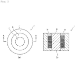
- Fig. 2 (a) is a plan view of a pot-shaped magnetic element in which the magnetic element shown in Fig. 1 is restrained from generating heat and improved in its heat dissipation performance.
- Fig. 2(b) is a sectional view taken along a line A-A shown in Fig. 2(a) .
- the coil 4 can be positively cooled.
- Fig. 3 (a) is a plan view of a pot-shaped magnetic element in which the magnetic element shown in Fig. 2 is restrained from generating heat and improved in its heat dissipation performance.
- Fig. 3(b) is a sectional view taken along a line A-A shown in Fig. 3(a) .
- the compression molded magnetic body 2b By forming the compression molded magnetic body 2b on the periphery of the end surface 2a of the compression molded magnetic body which contacts the cooling surface, the area of the end surface 2a of the compression molded magnetic body which contacts the cooling surface is increased. Thereby the coil 4 can be positively cooled.
- the upper and lower injection molded magnetic bodies have the same configuration, it is possible to decrease the number of dies and thus decrease the cost.
- Fig. 4 (a) is a plan view of a pot-shaped magnetic element adjustable in the magnetic characteristic of the magnetic element shown in Fig. 1 .
- Fig. 4(b) is a sectional view taken along a line A-A shown in Fig. 4(a) .
- the coil 4 is mounted inside the pot-shaped magnetic element 1 which is the combined body of the compression molded magnetic body 2 and the injection molded magnetic body 3.
- the illustration of the terminal of the coil 4 is omitted herein.
- the combined body of the compression molded magnetic body 2 and the injection molded magnetic body 3 is divided into two halves along the intermediate line 5 disposed at the intermediate position in the axial direction of the pot-shaped magnetic element.
- the axial length of the compression molded magnetic body 2 is set shorter than that of the injection molded magnetic body 3.
- the end surface 2a of the compression molded magnetic body 2 and the end surface 3a of the injection molded magnetic body 3 are on the same plane. Therefore the compression molded magnetic body 2 has a void portion 6 therein. By adjusting the length t of the void portion 6, it is possible to control the characteristics of the pot-shaped magnetic element such as its saturation magnetic flux density.
- Fig. 5 shows one example of a magnetic element of a comparative example.
- Fig. 5 shows an example in which the coil 4 is disposed inside the injection molded magnetic body 3.
- the injection molded magnetic body 3 is divided into two halves along the intermediate line 5 disposed at the intermediate position in the axial direction of the pot-shaped magnetic element. After the coil 4 is mounted inside the injection molded magnetic body 3, the two halves are combined with each other along the intermediate line 5. Thereby the pot-shaped magnetic element is obtained.
- the heat generation situations of the magnetic elements were analyzed by performing coupled analysis of electromagnetic field analysis and thermal analysis by using a finite element method.
- the results are shown below. Specimens used in the test were the same in the configurations of the magnetic elements, the kinds of the coils, and the number of turns of the coils.
- the height of each columnar magnetic element used in the test was 30mm.
- the diameter of each columnar magnetic element was 45mm.
- Figs. 6 through 8 which are perspective views of the magnetic elements circumferentially cut.
- Fig. 6 shows an example of the magnetic element shown in Fig. 1 .
- Fig. 7 shows an example of the magnetic element shown in Fig. 3 .
- Fig. 8 shows an example of the magnetic element shown in Fig.
- FIG. 5 as the comparative example.
- the illustration of the coils is omitted in Figs. 6 through 8 .
- a lower part of the magnetic element shown in Figs. 6 through 8 is in contact with a cooling portion.
- Figs. 6 through 8 because the temperatures of respective portions are shown not in multicolor but in grayscale, the temperatures of elliptic regions and those of the peripheral portions of the pot-shaped magnetic elements are illustrated with numerals.
- the pot-shaped magnetic elements shown in Figs. 6 and 7 in which the compression molded magnetic body excellent in its thermal conductivity is disposed at the inside diameter side of the coil and the injection molded magnetic body is disposed at a portion other than the inside diameter side of the coil are capable of reducing the temperature on the periphery of the coil to a higher extent than the pot-shaped magnetic element, shown in Fig. 8 , which is produced from only the injection molded magnetic body.
- the magnetic element of the present invention can be used for power circuits of cars including a two-wheeled vehicle, industrial equipment, and medical equipment; filter circuits; switching circuits, and the like.
- the magnetic element of the present invention can be used as an inductor, a transformer, an antenna, a choke coil, a filter, and the like.
- the magnetic element can be also used as surface mounting components.
- the magnetic element of the present invention is capable greatly reducing iron loss and excellent in its heat dissipation performance, it is possible to efficiently operate electrical and electronic equipment in the future.
Landscapes
- Engineering & Computer Science (AREA)
- Power Engineering (AREA)
- Chemical & Material Sciences (AREA)
- Composite Materials (AREA)
- Coils Or Transformers For Communication (AREA)
- Soft Magnetic Materials (AREA)
- Manufacturing Cores, Coils, And Magnets (AREA)
Applications Claiming Priority (2)
| Application Number | Priority Date | Filing Date | Title |
|---|---|---|---|
| JP2014060578A JP6374683B2 (ja) | 2014-03-24 | 2014-03-24 | 磁性素子 |
| PCT/JP2015/058016 WO2015146739A1 (ja) | 2014-03-24 | 2015-03-18 | 磁性素子 |
Publications (3)
| Publication Number | Publication Date |
|---|---|
| EP3125259A1 true EP3125259A1 (de) | 2017-02-01 |
| EP3125259A4 EP3125259A4 (de) | 2018-01-24 |
| EP3125259B1 EP3125259B1 (de) | 2020-01-01 |
Family
ID=54195261
Family Applications (1)
| Application Number | Title | Priority Date | Filing Date |
|---|---|---|---|
| EP15768781.5A Active EP3125259B1 (de) | 2014-03-24 | 2015-03-18 | Magnetisches element |
Country Status (5)
| Country | Link |
|---|---|
| US (1) | US10074471B2 (de) |
| EP (1) | EP3125259B1 (de) |
| JP (1) | JP6374683B2 (de) |
| CN (1) | CN106104718B (de) |
| WO (1) | WO2015146739A1 (de) |
Cited By (2)
| Publication number | Priority date | Publication date | Assignee | Title |
|---|---|---|---|---|
| JP2019504492A (ja) * | 2015-12-17 | 2019-02-14 | コミッサリア ア レネルジー アトミーク エ オ ゼネルジ ザルタナテイヴ | 低磁気損失を示すインダクタコア |
| EP3432325A4 (de) * | 2016-03-15 | 2019-11-20 | NTN Corporation | Magnetisches element |
Families Citing this family (8)
| Publication number | Priority date | Publication date | Assignee | Title |
|---|---|---|---|---|
| JP6465459B2 (ja) * | 2015-12-24 | 2019-02-06 | 株式会社オートネットワーク技術研究所 | 複合材料成形体、リアクトル、及び複合材料成形体の製造方法 |
| KR20170118430A (ko) | 2016-04-15 | 2017-10-25 | 삼성전기주식회사 | 코일 전자부품 및 그 제조방법 |
| CN106409488A (zh) * | 2016-05-12 | 2017-02-15 | 延安璟达电子科技有限公司 | 一种采用非晶微晶材料制造功率扼流圈的方法 |
| WO2017199935A1 (ja) * | 2016-05-20 | 2017-11-23 | 株式会社神戸製鋼所 | 磁心 |
| JP6964971B2 (ja) * | 2016-05-20 | 2021-11-10 | 株式会社神戸製鋼所 | 磁心 |
| JP7021459B2 (ja) * | 2017-05-02 | 2022-02-17 | Tdk株式会社 | インダクタ素子 |
| FR3083365B1 (fr) * | 2018-06-27 | 2020-07-17 | Safran Electronics & Defense | Transformateur comportant un circuit imprime |
| JP7253891B2 (ja) * | 2018-09-26 | 2023-04-07 | Ntn株式会社 | インダクタ |
Family Cites Families (16)
| Publication number | Priority date | Publication date | Assignee | Title |
|---|---|---|---|---|
| JP2000269039A (ja) * | 1999-03-16 | 2000-09-29 | Tdk Corp | 低背型表面実装コイル部品 |
| JP2002057039A (ja) * | 2000-08-11 | 2002-02-22 | Hitachi Ferrite Electronics Ltd | 複合磁芯 |
| JP4763609B2 (ja) | 2004-08-23 | 2011-08-31 | 日本科学冶金株式会社 | 磁性コア部品の製造方法 |
| US8466764B2 (en) * | 2006-09-12 | 2013-06-18 | Cooper Technologies Company | Low profile layered coil and cores for magnetic components |
| JP2008085004A (ja) * | 2006-09-27 | 2008-04-10 | Tdk Corp | 疎結合トランス及びスイッチング電源 |
| JP5341306B2 (ja) * | 2006-10-31 | 2013-11-13 | 住友電気工業株式会社 | リアクトル |
| JP2009033051A (ja) * | 2007-07-30 | 2009-02-12 | Sumitomo Electric Ind Ltd | リアクトル用コア |
| US8289116B2 (en) * | 2009-04-06 | 2012-10-16 | Delphi Technologies, Inc. | Ignition coil for vehicle |
| WO2011118004A1 (ja) * | 2010-03-25 | 2011-09-29 | パナソニック電工株式会社 | トランス |
| CN102810386B (zh) * | 2011-05-31 | 2016-07-13 | 美桀电子科技(深圳)有限公司 | 复合式磁芯及其制法 |
| US9202618B2 (en) * | 2011-09-20 | 2015-12-01 | Daido Steel Co., Ltd. | Injection-molded reactor and compound used in same |
| JP5928974B2 (ja) * | 2011-10-19 | 2016-06-01 | 住友電気工業株式会社 | リアクトル、コンバータ、及び電力変換装置 |
| JP6062676B2 (ja) | 2012-07-25 | 2017-01-18 | Ntn株式会社 | 複合磁性コアおよび磁性素子 |
| JP2014209579A (ja) | 2013-03-25 | 2014-11-06 | Ntn株式会社 | 電気回路用コアおよびこれを用いた装置 |
| KR101470513B1 (ko) * | 2013-07-17 | 2014-12-08 | 주식회사 아모그린텍 | 대전류 직류중첩특성 및 코어손실 특성이 우수한 연자성 코어 및 그의 제조방법 |
| JP2015159144A (ja) * | 2014-02-21 | 2015-09-03 | ミツミ電機株式会社 | インダクタ |
-
2014
- 2014-03-24 JP JP2014060578A patent/JP6374683B2/ja active Active
-
2015
- 2015-03-18 US US15/128,893 patent/US10074471B2/en active Active
- 2015-03-18 WO PCT/JP2015/058016 patent/WO2015146739A1/ja active Application Filing
- 2015-03-18 EP EP15768781.5A patent/EP3125259B1/de active Active
- 2015-03-18 CN CN201580015777.8A patent/CN106104718B/zh active Active
Cited By (3)
| Publication number | Priority date | Publication date | Assignee | Title |
|---|---|---|---|---|
| JP2019504492A (ja) * | 2015-12-17 | 2019-02-14 | コミッサリア ア レネルジー アトミーク エ オ ゼネルジ ザルタナテイヴ | 低磁気損失を示すインダクタコア |
| US11309109B2 (en) | 2015-12-17 | 2022-04-19 | Commissariat A L'energie Atomique Et Aux Energies Alternatives | Inductive core exhibiting low magnetic losses |
| EP3432325A4 (de) * | 2016-03-15 | 2019-11-20 | NTN Corporation | Magnetisches element |
Also Published As
| Publication number | Publication date |
|---|---|
| EP3125259A4 (de) | 2018-01-24 |
| WO2015146739A1 (ja) | 2015-10-01 |
| JP6374683B2 (ja) | 2018-08-15 |
| US10074471B2 (en) | 2018-09-11 |
| CN106104718B (zh) | 2019-01-11 |
| CN106104718A (zh) | 2016-11-09 |
| JP2015185673A (ja) | 2015-10-22 |
| EP3125259B1 (de) | 2020-01-01 |
| US20170110233A1 (en) | 2017-04-20 |
Similar Documents
| Publication | Publication Date | Title |
|---|---|---|
| EP3125259B1 (de) | Magnetisches element | |
| US10204725B2 (en) | Composite magnetic core and magnetic element | |
| KR101204873B1 (ko) | 자성 코어부품의 제조방법 | |
| EP3352182B1 (de) | Magnetisches element | |
| US10650951B2 (en) | Magnetic element | |
| JP2012004390A (ja) | リアクトル | |
| US20160343486A1 (en) | Coil electronic component and method of manufacturing the same | |
| EP3203488A1 (de) | Magnetkernkomponente und chipinduktor | |
| WO2017047740A1 (ja) | 磁性素子 | |
| JP2015185776A (ja) | 磁性コア部品および磁性素子、ならびに磁性コア部品の製造方法 | |
| JP2019153808A (ja) | 磁性素子 | |
| JP6529825B2 (ja) | 磁性素子 | |
| JP6676405B2 (ja) | 磁性素子 | |
| US20200402707A1 (en) | Magnetic element | |
| US20170062116A1 (en) | Coil electronic component and method of manufacturing the same |
Legal Events
| Date | Code | Title | Description |
|---|---|---|---|
| STAA | Information on the status of an ep patent application or granted ep patent |
Free format text: STATUS: THE INTERNATIONAL PUBLICATION HAS BEEN MADE |
|
| PUAI | Public reference made under article 153(3) epc to a published international application that has entered the european phase |
Free format text: ORIGINAL CODE: 0009012 |
|
| STAA | Information on the status of an ep patent application or granted ep patent |
Free format text: STATUS: REQUEST FOR EXAMINATION WAS MADE |
|
| 17P | Request for examination filed |
Effective date: 20161010 |
|
| AK | Designated contracting states |
Kind code of ref document: A1 Designated state(s): AL AT BE BG CH CY CZ DE DK EE ES FI FR GB GR HR HU IE IS IT LI LT LU LV MC MK MT NL NO PL PT RO RS SE SI SK SM TR |
|
| AX | Request for extension of the european patent |
Extension state: BA ME |
|
| DAV | Request for validation of the european patent (deleted) | ||
| DAX | Request for extension of the european patent (deleted) | ||
| RIN1 | Information on inventor provided before grant (corrected) |
Inventor name: MIYAZAKI, SHINJI Inventor name: ODA, TAKAYUKI Inventor name: SAKAI, KAYO Inventor name: SHIMAZU, EIICHIROU |
|
| A4 | Supplementary search report drawn up and despatched |
Effective date: 20180104 |
|
| RIC1 | Information provided on ipc code assigned before grant |
Ipc: H01F 27/255 20060101ALI20171221BHEP Ipc: H01F 27/24 20060101AFI20171221BHEP |
|
| GRAP | Despatch of communication of intention to grant a patent |
Free format text: ORIGINAL CODE: EPIDOSNIGR1 |
|
| STAA | Information on the status of an ep patent application or granted ep patent |
Free format text: STATUS: GRANT OF PATENT IS INTENDED |
|
| INTG | Intention to grant announced |
Effective date: 20190828 |
|
| GRAS | Grant fee paid |
Free format text: ORIGINAL CODE: EPIDOSNIGR3 |
|
| GRAA | (expected) grant |
Free format text: ORIGINAL CODE: 0009210 |
|
| STAA | Information on the status of an ep patent application or granted ep patent |
Free format text: STATUS: THE PATENT HAS BEEN GRANTED |
|
| AK | Designated contracting states |
Kind code of ref document: B1 Designated state(s): AL AT BE BG CH CY CZ DE DK EE ES FI FR GB GR HR HU IE IS IT LI LT LU LV MC MK MT NL NO PL PT RO RS SE SI SK SM TR |
|
| REG | Reference to a national code |
Ref country code: GB Ref legal event code: FG4D |
|
| REG | Reference to a national code |
Ref country code: CH Ref legal event code: EP Ref country code: AT Ref legal event code: REF Ref document number: 1220829 Country of ref document: AT Kind code of ref document: T Effective date: 20200115 |
|
| REG | Reference to a national code |
Ref country code: DE Ref legal event code: R096 Ref document number: 602015044726 Country of ref document: DE |
|
| REG | Reference to a national code |
Ref country code: IE Ref legal event code: FG4D |
|
| REG | Reference to a national code |
Ref country code: NL Ref legal event code: MP Effective date: 20200101 |
|
| REG | Reference to a national code |
Ref country code: LT Ref legal event code: MG4D |
|
| PG25 | Lapsed in a contracting state [announced via postgrant information from national office to epo] |
Ref country code: PT Free format text: LAPSE BECAUSE OF FAILURE TO SUBMIT A TRANSLATION OF THE DESCRIPTION OR TO PAY THE FEE WITHIN THE PRESCRIBED TIME-LIMIT Effective date: 20200527 Ref country code: CZ Free format text: LAPSE BECAUSE OF FAILURE TO SUBMIT A TRANSLATION OF THE DESCRIPTION OR TO PAY THE FEE WITHIN THE PRESCRIBED TIME-LIMIT Effective date: 20200101 Ref country code: NO Free format text: LAPSE BECAUSE OF FAILURE TO SUBMIT A TRANSLATION OF THE DESCRIPTION OR TO PAY THE FEE WITHIN THE PRESCRIBED TIME-LIMIT Effective date: 20200401 Ref country code: RS Free format text: LAPSE BECAUSE OF FAILURE TO SUBMIT A TRANSLATION OF THE DESCRIPTION OR TO PAY THE FEE WITHIN THE PRESCRIBED TIME-LIMIT Effective date: 20200101 Ref country code: LT Free format text: LAPSE BECAUSE OF FAILURE TO SUBMIT A TRANSLATION OF THE DESCRIPTION OR TO PAY THE FEE WITHIN THE PRESCRIBED TIME-LIMIT Effective date: 20200101 Ref country code: NL Free format text: LAPSE BECAUSE OF FAILURE TO SUBMIT A TRANSLATION OF THE DESCRIPTION OR TO PAY THE FEE WITHIN THE PRESCRIBED TIME-LIMIT Effective date: 20200101 Ref country code: FI Free format text: LAPSE BECAUSE OF FAILURE TO SUBMIT A TRANSLATION OF THE DESCRIPTION OR TO PAY THE FEE WITHIN THE PRESCRIBED TIME-LIMIT Effective date: 20200101 |
|
| PG25 | Lapsed in a contracting state [announced via postgrant information from national office to epo] |
Ref country code: IS Free format text: LAPSE BECAUSE OF FAILURE TO SUBMIT A TRANSLATION OF THE DESCRIPTION OR TO PAY THE FEE WITHIN THE PRESCRIBED TIME-LIMIT Effective date: 20200501 Ref country code: GR Free format text: LAPSE BECAUSE OF FAILURE TO SUBMIT A TRANSLATION OF THE DESCRIPTION OR TO PAY THE FEE WITHIN THE PRESCRIBED TIME-LIMIT Effective date: 20200402 Ref country code: HR Free format text: LAPSE BECAUSE OF FAILURE TO SUBMIT A TRANSLATION OF THE DESCRIPTION OR TO PAY THE FEE WITHIN THE PRESCRIBED TIME-LIMIT Effective date: 20200101 Ref country code: LV Free format text: LAPSE BECAUSE OF FAILURE TO SUBMIT A TRANSLATION OF THE DESCRIPTION OR TO PAY THE FEE WITHIN THE PRESCRIBED TIME-LIMIT Effective date: 20200101 Ref country code: SE Free format text: LAPSE BECAUSE OF FAILURE TO SUBMIT A TRANSLATION OF THE DESCRIPTION OR TO PAY THE FEE WITHIN THE PRESCRIBED TIME-LIMIT Effective date: 20200101 Ref country code: BG Free format text: LAPSE BECAUSE OF FAILURE TO SUBMIT A TRANSLATION OF THE DESCRIPTION OR TO PAY THE FEE WITHIN THE PRESCRIBED TIME-LIMIT Effective date: 20200401 |
|
| REG | Reference to a national code |
Ref country code: DE Ref legal event code: R097 Ref document number: 602015044726 Country of ref document: DE |
|
| PG25 | Lapsed in a contracting state [announced via postgrant information from national office to epo] |
Ref country code: DK Free format text: LAPSE BECAUSE OF FAILURE TO SUBMIT A TRANSLATION OF THE DESCRIPTION OR TO PAY THE FEE WITHIN THE PRESCRIBED TIME-LIMIT Effective date: 20200101 Ref country code: MC Free format text: LAPSE BECAUSE OF FAILURE TO SUBMIT A TRANSLATION OF THE DESCRIPTION OR TO PAY THE FEE WITHIN THE PRESCRIBED TIME-LIMIT Effective date: 20200101 Ref country code: EE Free format text: LAPSE BECAUSE OF FAILURE TO SUBMIT A TRANSLATION OF THE DESCRIPTION OR TO PAY THE FEE WITHIN THE PRESCRIBED TIME-LIMIT Effective date: 20200101 Ref country code: ES Free format text: LAPSE BECAUSE OF FAILURE TO SUBMIT A TRANSLATION OF THE DESCRIPTION OR TO PAY THE FEE WITHIN THE PRESCRIBED TIME-LIMIT Effective date: 20200101 Ref country code: RO Free format text: LAPSE BECAUSE OF FAILURE TO SUBMIT A TRANSLATION OF THE DESCRIPTION OR TO PAY THE FEE WITHIN THE PRESCRIBED TIME-LIMIT Effective date: 20200101 Ref country code: SK Free format text: LAPSE BECAUSE OF FAILURE TO SUBMIT A TRANSLATION OF THE DESCRIPTION OR TO PAY THE FEE WITHIN THE PRESCRIBED TIME-LIMIT Effective date: 20200101 Ref country code: SM Free format text: LAPSE BECAUSE OF FAILURE TO SUBMIT A TRANSLATION OF THE DESCRIPTION OR TO PAY THE FEE WITHIN THE PRESCRIBED TIME-LIMIT Effective date: 20200101 |
|
| REG | Reference to a national code |
Ref country code: CH Ref legal event code: PL |
|
| PLBE | No opposition filed within time limit |
Free format text: ORIGINAL CODE: 0009261 |
|
| STAA | Information on the status of an ep patent application or granted ep patent |
Free format text: STATUS: NO OPPOSITION FILED WITHIN TIME LIMIT |
|
| REG | Reference to a national code |
Ref country code: AT Ref legal event code: MK05 Ref document number: 1220829 Country of ref document: AT Kind code of ref document: T Effective date: 20200101 |
|
| 26N | No opposition filed |
Effective date: 20201002 |
|
| REG | Reference to a national code |
Ref country code: BE Ref legal event code: MM Effective date: 20200331 |
|
| PG25 | Lapsed in a contracting state [announced via postgrant information from national office to epo] |
Ref country code: LU Free format text: LAPSE BECAUSE OF NON-PAYMENT OF DUE FEES Effective date: 20200318 |
|
| PG25 | Lapsed in a contracting state [announced via postgrant information from national office to epo] |
Ref country code: LI Free format text: LAPSE BECAUSE OF NON-PAYMENT OF DUE FEES Effective date: 20200331 Ref country code: IT Free format text: LAPSE BECAUSE OF FAILURE TO SUBMIT A TRANSLATION OF THE DESCRIPTION OR TO PAY THE FEE WITHIN THE PRESCRIBED TIME-LIMIT Effective date: 20200101 Ref country code: IE Free format text: LAPSE BECAUSE OF NON-PAYMENT OF DUE FEES Effective date: 20200318 Ref country code: CH Free format text: LAPSE BECAUSE OF NON-PAYMENT OF DUE FEES Effective date: 20200331 Ref country code: AT Free format text: LAPSE BECAUSE OF FAILURE TO SUBMIT A TRANSLATION OF THE DESCRIPTION OR TO PAY THE FEE WITHIN THE PRESCRIBED TIME-LIMIT Effective date: 20200101 |
|
| PG25 | Lapsed in a contracting state [announced via postgrant information from national office to epo] |
Ref country code: BE Free format text: LAPSE BECAUSE OF NON-PAYMENT OF DUE FEES Effective date: 20200331 Ref country code: SI Free format text: LAPSE BECAUSE OF FAILURE TO SUBMIT A TRANSLATION OF THE DESCRIPTION OR TO PAY THE FEE WITHIN THE PRESCRIBED TIME-LIMIT Effective date: 20200101 Ref country code: PL Free format text: LAPSE BECAUSE OF FAILURE TO SUBMIT A TRANSLATION OF THE DESCRIPTION OR TO PAY THE FEE WITHIN THE PRESCRIBED TIME-LIMIT Effective date: 20200101 |
|
| GBPC | Gb: european patent ceased through non-payment of renewal fee |
Effective date: 20200401 |
|
| PG25 | Lapsed in a contracting state [announced via postgrant information from national office to epo] |
Ref country code: GB Free format text: LAPSE BECAUSE OF NON-PAYMENT OF DUE FEES Effective date: 20200401 |
|
| PG25 | Lapsed in a contracting state [announced via postgrant information from national office to epo] |
Ref country code: TR Free format text: LAPSE BECAUSE OF FAILURE TO SUBMIT A TRANSLATION OF THE DESCRIPTION OR TO PAY THE FEE WITHIN THE PRESCRIBED TIME-LIMIT Effective date: 20200101 Ref country code: MT Free format text: LAPSE BECAUSE OF FAILURE TO SUBMIT A TRANSLATION OF THE DESCRIPTION OR TO PAY THE FEE WITHIN THE PRESCRIBED TIME-LIMIT Effective date: 20200101 Ref country code: CY Free format text: LAPSE BECAUSE OF FAILURE TO SUBMIT A TRANSLATION OF THE DESCRIPTION OR TO PAY THE FEE WITHIN THE PRESCRIBED TIME-LIMIT Effective date: 20200101 |
|
| PG25 | Lapsed in a contracting state [announced via postgrant information from national office to epo] |
Ref country code: MK Free format text: LAPSE BECAUSE OF FAILURE TO SUBMIT A TRANSLATION OF THE DESCRIPTION OR TO PAY THE FEE WITHIN THE PRESCRIBED TIME-LIMIT Effective date: 20200101 Ref country code: AL Free format text: LAPSE BECAUSE OF FAILURE TO SUBMIT A TRANSLATION OF THE DESCRIPTION OR TO PAY THE FEE WITHIN THE PRESCRIBED TIME-LIMIT Effective date: 20200101 |
|
| PGFP | Annual fee paid to national office [announced via postgrant information from national office to epo] |
Ref country code: DE Payment date: 20240130 Year of fee payment: 10 |
|
| PGFP | Annual fee paid to national office [announced via postgrant information from national office to epo] |
Ref country code: FR Payment date: 20240213 Year of fee payment: 10 |