EP3124718A1 - Smoothing or pressing tool - Google Patents
Smoothing or pressing tool Download PDFInfo
- Publication number
- EP3124718A1 EP3124718A1 EP16181734.1A EP16181734A EP3124718A1 EP 3124718 A1 EP3124718 A1 EP 3124718A1 EP 16181734 A EP16181734 A EP 16181734A EP 3124718 A1 EP3124718 A1 EP 3124718A1
- Authority
- EP
- European Patent Office
- Prior art keywords
- smoothing
- lip
- tool
- support member
- longitudinal
- Prior art date
- Legal status (The legal status is an assumption and is not a legal conclusion. Google has not performed a legal analysis and makes no representation as to the accuracy of the status listed.)
- Withdrawn
Links
Images
Classifications
-
- E—FIXED CONSTRUCTIONS
- E04—BUILDING
- E04F—FINISHING WORK ON BUILDINGS, e.g. STAIRS, FLOORS
- E04F21/00—Implements for finishing work on buildings
- E04F21/02—Implements for finishing work on buildings for applying plasticised masses to surfaces, e.g. plastering walls
- E04F21/16—Implements for after-treatment of plaster or the like before it has hardened or dried, e.g. smoothing-tools, profile trowels
- E04F21/161—Trowels
Definitions
- the present invention relates to a tool for smoothing or marouflage and a method of manufacturing this tool.
- the rigidity of the metal blades although these tend to bend slightly under the effect of the user's support force, may have the disadvantage, if this effort exerted by the user is important, to cause more raking of the coating than smoothing it. This results in a lower quality of the surface of the coating after the tool has passed: small thickness, irregularities, etc.
- the present invention aims to overcome this disadvantage by providing a coating tool for spreading a coating without scraping.
- the subject of the present invention is a smoothing or marouflaging tool comprising a support member and a longitudinal smoothing lip supported by the support member, the smoothing lip being made of plastic or elastomer, characterized in that the support member comprises a projection extending along at least half the width of the smoothing lip to a bending edge for bending the smoothing lip.
- the tool according to the invention offers the possibility of uniformly spreading a coating, without removing it completely, leaving a desired thickness.
- the smoothing lip, plastic or elastomeric is flexible, easily deformable, and folds easily during use, which avoids scraping the coating.
- the advance which extends over at least half of the width of the flexible smoothing lip and whose bending edge presses on the flexible lip puts it in cantilever, and causes in reaction an elastic pivot effect of the lip around the bending edge, so that the free end of the lip strongly presses the coating so as to spread quality.
- the support member has a lower surface
- the smoothing lip comprises a lower smoothing surface arranged in the extension of the lower surface of the support member.
- This characteristic allows a flat smoothing and a good distribution of the coating.
- the lower smoothing surface is free and extends at least partially under the advancing of the support member.
- This lower smoothing surface, being free, is more easily deformed. This improves the booster effect of the free end of the lip, thus the quality of the spreading of the coating.
- the lower surface of the support member and the projection are separated by a shoulder, and the smoothing lip has a longitudinal side fixed to this shoulder.
- the advance has, between the bending edge and the shoulder, a lower bearing surface, and the smoothing lip has an upper surface fixed to this lower bearing surface.
- the bending edge is substantially rectilinear.
- This feature improves the flatness of the coating resulting from smoothing.
- the smoothing lip has a first longitudinal portion, and a second longitudinal portion having a decreasing thickness from the first longitudinal portion to a free longitudinal smoothing edge, the advance extending only beyond above the first longitudinal portion.
- the bending edge extends at the level of the boundary between the first and the second longitudinal portion of the smoothing lip.
- the bending edge bends where the thickness of the smoothing lip begins to decrease. This allows for greater sagging of the thin portion of the smoothing lip, that is to say the second portion, during use, to obtain a flat smoothing preserving a thickness of coating, without raking it.
- the advance has an upper surface on which is provided a concavity for receiving the fingers of a user.
- This feature advantageously allows the user to feel the touch the appropriate effort to apply. This results in the possibility of performing a significantly improved quality smoothing, for any type of coating and coated surface.
- the invention also relates to a method of manufacturing a tool having the aforementioned characteristics, wherein the support member and the smoothing lip are coextruded
- This method has the advantage of allowing the manufacture of the tool according to the invention quickly and at lower cost.
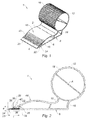
- the figure 1 shows a smoothing tool 1 according to one embodiment of the invention.
- This smoothing tool 1 is intended to smooth a product such as a coating or an adhesive.
- the tool 1 according to the invention is thus for example for the smoothing of plaster, tile joint, marouflage, including glass cloths, wallpapers, thermal insulation coating from the outside, etc.
- the smoothing tool 1 comprises a support member 2 and a longitudinal smoothing lip 4 supported by the support member 2.
- the support member 2 is for example a profile. It is made of a rigid material, for example a rigid PVC.
- the support member 2 here comprises a sole portion 6, having in particular a lower surface 8 which can be substantially flat, and moreover an upper surface 10 which is advantageously substantially convex.
- the support member 2 may further comprise a portion 12 of gripping, allowing either the attachment of a handling boom, or a manual entry by a user, to manipulate the tool 1.
- the gripping portion 12 is advantageously connected to the sole portion 6 by an intermediate connecting portion 14, delimiting in particular between the sole portion 6 and the gripping portion 12 one or two concavities 16 allowing a wide range of angular adjustment of the inclination of a pole on the portion 12 of gripping.
- the portion 12 of gripping advantageously has a circular section, more particularly from one to the other of the concavities 16, between them; this gripping portion 12 is for example cylindrical.
- this allows a plurality of possible relative positions of a pole on this portion 12 of gripping, the boom can be fixed by means of jaws for tightening around the portion 12 of gripping.
- the gripping portion 12 may advantageously comprise ridges 18, which may be substantially parallel to each other, and parallel to a longitudinal axis A passing through the center of the portion 12 of gripping. These ridges 18 advantageously make it possible to limit any unexpected relative sliding of the pole relative to the portion 12 of grip. These grooves 18 are particularly suitable for use with a pole whose jaws intended to close on the portion 12 of gripping comprise a deformable material such as an elastomeric material which will be housed in the grooves defined between the grooves 18.
- the intermediate portion 14 of connection is of lesser thickness, that is to say of width L substantially less than a diameter of the portion 12 of gripping, preferably a radius of the portion 12 of gripping.
- the support member 2 is advantageously one and the same piece.
- the smoothing lip 4 is made of a flexible, deformable material intended to flex under the effect of a force exerted by the user during use of the tool 1 for smoothing or marouflaging.
- the smoothing lip 4 is made of plastic or elastomer.
- the smoothing lip 4 promotes a display of the coating without raking it, unlike what can happen with metal blades.
- the smoothing lip 4 extends longitudinally along one side of the support member 2, in particular of the sole portion 6, which is here a side opposite to that where the portion 12 extends. grasping. Preferably, the smoothing lip 4 extends all along one side of the support member 2.
- the smoothing lip 4 has a lower smoothing surface for smoothing or marbling a coating, and an upper surface 22 opposite to the lower surface.
- the smoothing lip 4 has a free front longitudinal edge 24 for smoothing or marouflaging a coating, and a rear longitudinal edge 26 opposite to the free front longitudinal edge 24.
- the support member 2 and the smoothing lip 4 are preferably coextruded.
- the support member 2 and the smoothing lip 4 can therefore be produced simultaneously by coextrusion and hot-assembled at the die outlet. Coextrusion allows for quick manufacturing at a lower cost.
- this technique offers the possibility of making tools 1 of different lengths by the same method, by cutting the profile obtained according to a plurality of predetermined working lengths for the tool 1.
- the tool 1 has a projection 28 which extends over the smoothing lip 4 over at least half of the width 1 of the smoothing lip 4 to a deflection edge for deflection. lip 4 of smoothing during a smoothing operation or marouflage.
- the bending edge 30 is preferably rigid, as opposed to the smoothing lip 4.
- the edge 30 is advantageously rectilinear, and substantially parallel to the direction in which the lip 4 of smoothing extends longitudinally.
- the advance 28 extends along the side of the support member 2 where the smoothing lip 4 is located, along this smoothing lip 4, preferably over the entire length thereof.
- the bending edge 30 is arranged substantially equidistant from the front longitudinal edge 24 and the rear longitudinal edge 26 of the smoothing lip 4, or closer to the longitudinal edge 24 before the rear longitudinal edge 26.
- the projection 28 extends here from a shoulder 32 of the lower surface 8 of the sole portion 6 to the bending edge 30.
- the rear longitudinal edge 26 of the smoothing lip 4 is here in abutment against the shoulder 32, preferably integral with the latter to promote rearward traction of the lip 4 during use.
- the distance separating the shoulder 32 from the bending edge 30 is substantially greater than or equal to half the width of the smoothing lip 4.
- Advantage 28 advantageously has a lower bearing surface 34 which covers at least half of the upper surface 22 of the smoothing lip 4.
- the upper surface 22 may be integral with the lower bearing surface 34.
- the upper surface 22 and the lower bearing surface 34 are advantageously flat.
- the lower surface 34 extends in particular from the shoulder 32 to the bending edge 30.
- the shoulder 32 may be substantially perpendicular to the lower surface 8 and / or the lower bearing surface 34.
- the lower bearing surface 34 may be substantially parallel to the lower smoothing surface and / or the lower surface 8.
- the lower smoothing surface is preferably arranged in the extension of the lower surface 8 of the support member 2.
- this lower smoothing surface and the lower surface 8 of the sole portion 6 are, when the tool 1 is not used, substantially coplanar. These surfaces 20, 8 may further be adjacent, that is to say in the continuity of one another.
- the lower smoothing surface is free and extends under at least a portion of the projection 28.
- the lower smoothing surface is completely free, that is, without contact with another element. of the tool 1, in particular between the two longitudinal edges 24, 26 of the smoothing lip 4.
- the smoothing lip 4 may be in two parts: the smoothing lip 4 may have a first longitudinal portion 36 and a second longitudinal portion 38, this second longitudinal portion 38 having a thickness e decreasing from the first portion 36 longitudinally adjacent to the front longitudinal edge 24.
- the two longitudinal portions 36, 38 are substantially parallel to the longitudinal direction in which the smoothing lip 4 extends. Advance 28 further extends only above the first longitudinal portion 36.
- the first portion 36 here has a thickness e sensibement constant.
- the longitudinal portion 36 may have a rectangular parallelepiped shape, while the second portion 38 has the shape of a triangular prism.
- the thickness of the first longitudinal portion 36 may be substantially similar to the distance between the lower bearing surface 34 and the lower surface 8, or at the height of the shoulder 32.
- the projection 28 may advantageously have an upper surface 40 on which is provided a concavity 42 for receiving the fingers of a user.
- the upper surface 40 in particular the concavity 42, may have grooves 46 or ribs substantially parallel to each other and parallel to the direction in which the lip 4 extends longitudinally smoothly and / or parallel to the edge 30 of sagging.
- the ridges or ribs may also extend over a convex portion 44 before the top surface which is adjacent to the concavity 42.
- the ridges or ribs on the concavity 42 and optionally on the forward convex portion 44 of the surface 10 superior avoid sliding a user's fingers.
- the invention also relates to a method of manufacturing a tool 1 having all or some of the features described above, wherein the support member 2 and the smoothing lip 4 are obtained by a coextrusion step.
Abstract
Cet outil (1) comprend un organe (2) de support et une lèvre (4) de lissage longitudinale supportée par l'organe (2) de support, la lèvre (4) de lissage étant en matière plastique ou élastomère. De plus, l'organe (2) de support comprend une avancée (28) s'étendant le long d'au moins la moitié de la largeur de la lèvre (4) de lissage jusqu'à une arête (30) de fléchissement destinée à faire fléchir la lèvre (4) de lissage.This tool (1) comprises a support member (2) and a longitudinal smoothing lip (4) supported by the support member (2), the smoothing lip (4) being made of plastic or elastomer. In addition, the support member (2) comprises a projection (28) extending along at least half the width of the smoothing lip (4) to a bending edge (30) for to bend the lip (4) of smoothing.
Description
La présente invention concerne un outil de lissage ou marouflage et un procédé de fabrication de cet outil.The present invention relates to a tool for smoothing or marouflage and a method of manufacturing this tool.
Au cours des dix dernières années, les techniques du bâtiment ont évolué et les opérations d'enduction se font maintenant à l'aide d'enduit préparé qui arrive sur les chantiers conditionné dans des seaux. Ces nouveaux enduits présentent une certaine liquidité qui permet de les appliquer par exemple au rouleau à peindre ou à la pompe.Over the last ten years, building techniques have evolved and coating operations are now done using prepared plaster that arrives on sites packed in buckets. These new coatings have a certain liquidity that allows them to be applied, for example, to the paint roller or the pump.
Il est connu de lisser l'enduit déposé au rouleau avec un couteau à enduire comportant traditionnellement une lame métallique solidaire d'un caisson.It is known to smooth the coating deposited with a roll with a coating knife traditionally comprising a metal blade secured to a box.
Cependant, la rigidité des lames métalliques, bien que celles-ci tendent à fléchir légèrement sous l'effet de l'effort d'appui de l'utilisateur, peut présenter l'inconvénient, si cet effort exercé par l'utilisateur est important, de provoquer davantage un ratissage de l'enduit qu'un lissage de celui-ci. Il en résulte une qualité moindre de la surface de l'enduit après passage de l'outil: faible épaisseur, irrégularités, etc.However, the rigidity of the metal blades, although these tend to bend slightly under the effect of the user's support force, may have the disadvantage, if this effort exerted by the user is important, to cause more raking of the coating than smoothing it. This results in a lower quality of the surface of the coating after the tool has passed: small thickness, irregularities, etc.
Aussi la présente invention a pour but de pallier cet inconvénient en proposant un outil à enduire permettant d'étaler un enduit sans le racler.Also the present invention aims to overcome this disadvantage by providing a coating tool for spreading a coating without scraping.
A cet effet, la présente invention a pour objet un outil de lissage ou marouflage comprenant un organe de support et une lèvre de lissage longitudinale supportée par l'organe de support, la lèvre de lissage étant en matière plastique ou élastomère, caractérisé en ce que l'organe de support comprend une avancée s'étendant le long d'au moins la moitié de la largeur de la lèvre de lissage jusqu'à une arête de fléchissement destinée à faire fléchir la lèvre de lissage.For this purpose, the subject of the present invention is a smoothing or marouflaging tool comprising a support member and a longitudinal smoothing lip supported by the support member, the smoothing lip being made of plastic or elastomer, characterized in that the support member comprises a projection extending along at least half the width of the smoothing lip to a bending edge for bending the smoothing lip.
Ainsi, l'outil selon l'invention offre la possibilité d'étaler uniformément un enduit, sans l'enlever complètement, en laissant une épaisseur souhaitée. En effet, la lèvre de lissage, en matière plastique ou élastomère, est souple, aisément déformable, et se plie facilement lors de l'utilisation, ce qui évite de racler l'enduit. De plus, l'avancée qui s'étend sur au moins la moitié de la largeur de la lèvre de lissage souple et dont l'arête de fléchissement appuie sur la lèvre souple, met celle-ci en porte-à-faux, et provoque en réaction un effet de pivot élastique de la lèvre autour de l'arête de fléchissement, si bien que l'extrémité libre de la lèvre appuie fortement sur l'enduit de manière à l'étaler avec qualité.Thus, the tool according to the invention offers the possibility of uniformly spreading a coating, without removing it completely, leaving a desired thickness. Indeed, the smoothing lip, plastic or elastomeric, is flexible, easily deformable, and folds easily during use, which avoids scraping the coating. In addition, the advance which extends over at least half of the width of the flexible smoothing lip and whose bending edge presses on the flexible lip, puts it in cantilever, and causes in reaction an elastic pivot effect of the lip around the bending edge, so that the free end of the lip strongly presses the coating so as to spread quality.
Selon un mode de réalisation préféré, l'organe de support présente une surface inférieure, et la lèvre de lissage comprend une surface inférieure de lissage agencée dans le prolongement de la surface inférieure de l'organe de support.According to a preferred embodiment, the support member has a lower surface, and the smoothing lip comprises a lower smoothing surface arranged in the extension of the lower surface of the support member.
Cette caractéristique permet un lissage à plat et une bonne répartition de l'enduit.This characteristic allows a flat smoothing and a good distribution of the coating.
Selon un mode de réalisation préféré, la surface inférieure de lissage est libre et s'étend au moins en partie sous l'avancée de l'organe de support.According to a preferred embodiment, the lower smoothing surface is free and extends at least partially under the advancing of the support member.
Cette surface inférieure de lissage, étant libre, se déforme plus aisément. Cela améliore l'effet de rappel de l'extrémité libre de la lèvre, donc la qualité de l'étalement de l'enduit.This lower smoothing surface, being free, is more easily deformed. This improves the booster effect of the free end of the lip, thus the quality of the spreading of the coating.
Selon un mode de réalisation préféré, la surface inférieure de l'organe de support et l'avancée sont séparées par un épaulement, et la lèvre de lissage a un côté longitudinal fixé à cet épaulement.According to a preferred embodiment, the lower surface of the support member and the projection are separated by a shoulder, and the smoothing lip has a longitudinal side fixed to this shoulder.
Ainsi, lorsque l'arête de fléchissement appui et déforme la lèvre de lissage, la partie arrière de la lèvre, c'est-à-dire la tranche solidaire de l'épaulement, est tractée par cet épaulement, ce qui favorise en réaction l'appui de l'extrémité libre de la lèvre contre l'enduit.Thus, when the bending edge supports and deforms the smoothing lip, the rear part of the lip, that is to say the edge integral with the shoulder, is drawn by this shoulder, which in turn promotes support of the free end of the lip against the coating.
Selon un mode de réalisation préféré, l'avancée présente, entre l'arête de fléchissement et l'épaulement, une surface inférieure d'appui, et la lèvre de lissage présente une surface supérieure fixée à cette surface inférieure d'appui.According to a preferred embodiment, the advance has, between the bending edge and the shoulder, a lower bearing surface, and the smoothing lip has an upper surface fixed to this lower bearing surface.
Ainsi, c'est essentiellement la surface inférieure de lissage de la lèvre souple qui se déforme, ce qui augmente la réaction de rappel de l'extrémité libre de la lèvre, donc la qualité d'étalement de l'enduit.Thus, it is essentially the lower smoothing surface of the flexible lip which is deformed, which increases the return reaction of the free end of the lip, thus the quality of spreading of the coating.
Selon un mode de réalisation préféré, l'arête de fléchissement est sensiblement rectiligne.According to a preferred embodiment, the bending edge is substantially rectilinear.
Cette caractéristique améliore la planéité de l'enduit résultant du lissage.This feature improves the flatness of the coating resulting from smoothing.
Selon un mode de réalisation préféré, la lèvre de lissage présente une première portion longitudinale, et une seconde portion longitudinale ayant une épaisseur décroissante depuis la première portion longitudinale jusqu'à un bord longitudinal libre de lissage, l'avancée s'étendant uniquement au-dessus de la première portion longitudinale.According to a preferred embodiment, the smoothing lip has a first longitudinal portion, and a second longitudinal portion having a decreasing thickness from the first longitudinal portion to a free longitudinal smoothing edge, the advance extending only beyond above the first longitudinal portion.
Cela introduit une progressivité dans la déformation de la partie avant de la lèvre souple, donc une progressivité dans l'effort exercé par la lèvre sur l'enduit, ce limite un raclage de l'enduit.This introduces a progressiveness in the deformation of the front portion of the flexible lip, so a progressivity in the force exerted by the lip on the coating, this limits a scraping of the coating.
Selon une possibilité avantageuse, l'arête de fléchissement s'étend au niveau de la limite entre la première et la deuxième portion longitudinale de la lèvre de lissage.According to an advantageous possibility, the bending edge extends at the level of the boundary between the first and the second longitudinal portion of the smoothing lip.
Ainsi, l'arête de fléchissement s'arête là où l'épaisseur de la lèvre de lissage commence à diminuer. Cela permet un fléchissement plus important de la partie mince de la lèvre de lissage, c'est-à-dire la deuxième portion, lors d'une utilisation, en vue d'obtenir un lissage à plat préservant une épaisseur d'enduit, sans ratisser celui-ci.Thus, the bending edge bends where the thickness of the smoothing lip begins to decrease. This allows for greater sagging of the thin portion of the smoothing lip, that is to say the second portion, during use, to obtain a flat smoothing preserving a thickness of coating, without raking it.
Selon un mode de réalisation préféré, l'avancée présente une surface supérieure sur laquelle est prévue une concavité permettant de recevoir les doigts d'un utilisateur.According to a preferred embodiment, the advance has an upper surface on which is provided a concavity for receiving the fingers of a user.
Cette caractéristique permet avantageusement à l'utilisateur de sentir par le toucher l'effort adéquat à appliquer. Il en résulte la possibilité d'effectuer un lissage de qualité sensiblement améliorée, pour toute nature d'enduit et de surface enduite.This feature advantageously allows the user to feel the touch the appropriate effort to apply. This results in the possibility of performing a significantly improved quality smoothing, for any type of coating and coated surface.
Selon un autre aspect, l'invention a aussi pour objet un procédé de fabrication d'un outil ayant les caractéristiques précitées, dans lequel l'organe de support et la lèvre de lissage sont co-extrudéesAccording to another aspect, the invention also relates to a method of manufacturing a tool having the aforementioned characteristics, wherein the support member and the smoothing lip are coextruded
Ce procédé a l'avantage de permettre la fabrication de l'outil selon l'invention rapidement et à moindres coûts.This method has the advantage of allowing the manufacture of the tool according to the invention quickly and at lower cost.
D'autres caractéristiques et avantages de la présente invention ressortiront clairement de la description détaillée ci-après d'un mode de réalisation, donné à titre d'exemple non limitatif, en référence aux dessins annexés dans lesquels :
- La
figure 1 est une vue en perspective d'un outil selon un mode de réalisation de l'invention, - La
figure 2 est une vue de côté d'un outil selon un mode de réalisation de l'invention.
- The
figure 1 is a perspective view of a tool according to an embodiment of the invention, - The
figure 2 is a side view of a tool according to one embodiment of the invention.
La
Comme illustré sur les
L'organe 2 de support est par exemple un profilé. Il est en un matériau rigide, par exemple un PVC rigide.The
L'organe 2 de support comprend ici une portion 6 de semelle, ayant notamment une surface 8 inférieure qui peut être sensiblement plane, et par ailleurs une surface 10 supérieure qui est avantageusement essentiellement convexe.The
Toujours selon l'exemple des
La portion 12 de préhension est avantageusement reliée à la portion 6 de semelle par une portion 14 intermédiaire de liaison, délimitant notamment entre la portion 6 de semelle et la portion 12 de préhension une ou deux concavités 16 permettant une plage large de réglage angulaire de l'inclinaison d'une perche sur la portion 12 de préhension.The gripping
La portion 12 de préhension présente avantageusement une section circulaire, plus particulièrement de l'une à l'autre des concavités 16, entre celles-ci ; cette portion 12 de préhension est par exemple cylindrique. Ainsi, cela autorise une pluralité de positionnements relatifs possibles d'une perche sur cette portion 12 de préhension, la perche pouvant y être fixée au moyen de mâchoires destinés se resserrer autour de la portion 12 de préhension.The
Aussi, la portion 12 de préhension peut avantageusement comporter des stries 18, pouvant être sensiblement parallèles entre elles, et parallèles à un axe longitudinal A passant par le centre de la portion 12 de préhension. Ces stries 18 permettent avantageusement de limiter tout glissement relatif inattendu de la perche relativement à la portion 12 de préhension. Ces stries 18 sont particulièrement adaptées pour une utilisation avec une perche dont les mâchoires destinées à se refermer sur la portion 12 de préhension comprennent un matériau déformable comme par exemple un matériau élastomère qui va se loger dans les rainures délimitées entre les stries 18.Also, the
La portion 14 intermédiaire de liaison est de moindre épaisseur, c'est-à-dire de largeur L sensiblement inférieure à un diamètre de la portion 12 de préhension, de préférence à un rayon de la portion 12 de préhension.The
On notera que l'organe 2 de support est avantageusement une seule et même pièce.It will be noted that the
La lèvre 4 de lissage est en un matériau souple, déformable, destiné à fléchir sous l'effet d'un effort exercé par l'utilisateur lors d'une utilisation de l'outil 1 pour un lissage ou marouflage. En particulier, la lèvre 4 de lissage est en matière plastique ou élastomère. Ainsi, la lèvre 4 de lissage favorise un étalage de l'enduit sans le ratisser, à la différence de ce qui peut arriver avec des lames métalliques.The
La lèvre 4 de lissage s'étend de manière longitudinale, le long d'un côté de l'organe 2 de support, en particulier de la portion 6 de semelle, qui est ici un côté opposé à celui où s'étend la portion 12 de préhension. De préférence, la lèvre 4 de lissage s'étend tout le long d'un côté de l'organe 2 de support.The
Selon l'exemple des
La lèvre 4 de lissage présente un bord 24 longitudinal avant, libre, destiné au lissage ou marouflage d'un enduit, et un bord 26 longitudinal arrière, opposé au bord 24 longitudinal avant libre.The
On notera que l'organe 2 de support et la lèvre 4 de lissage sont préférentiellement coextrudés. L'organe 2 de support et la lèvre 4 de lissage peuvent donc être réalisés simultanément par coextrusion et assemblés à chaud en sortie de filière. La coextrusion permet une fabrication rapide, à moindres coûts. En outre, cette technique offre la possibilité de réaliser, via un même procédé, des outils 1 de différentes longueurs, en coupant le profilé obtenu selon une pluralité de longueurs de travail prédéterminées pour l'outil 1.It will be noted that the
L'outil 1 présente une avancée 28 qui s'étend au-dessus de la lèvre 4 de lissage sur au moins la moitié de la largeur l de la lèvre 4 de lissage, jusqu'à une arête 30 de fléchissement destinée à faire fléchir la lèvre 4 de lissage lors d'une opération de lissage ou marouflage.The tool 1 has a
L'arête 30 de fléchissement est préférentiellement rigide, par opposition à la lèvre 4 de lissage souple.The bending
L'arête 30 est avantageusement rectiligne, et sensiblement parallèle à la direction dans laquelle s'étend longitudinalement la lèvre 4 de lissage.The
L'avancée 28 s'étend le long du côté de l'organe 2 de support où est située la lèvre 4 de lissage, le long de cette lèvre 4 de lissage, de préférence sur toute la longueur de celle-ci.The
L'arête 30 de fléchissement est agencée sensiblement à égale distance du bord 24 longitudinal avant et du bord 26 longitudinal arrière de la lèvre 4 de lissage, ou plus proche du bord 24 longitudinal avant que du bord 26 longitudinal arrière.The bending
Comme illustré sur les figures, l'avancée 28 s'étend ici à partir d'un épaulement 32 de la surface 8 inférieure de la portion 6 de semelle, jusqu'à l'arête 30 de fléchissement.As illustrated in the figures, the
Le bord 26 longitudinal arrière de la lèvre 4 de lissage est ici en appui contre l'épaulement 32, de préférence solidaire de celui-ci pour favoriser une traction vers l'arrière de la lèvre 4 lors d'une utilisation.The rear
La distance séparant l'épaulement 32 de l'arête 30 de fléchissement est sensiblement supérieure ou égale à la moitié de la largeur de la lèvre 4 de lissage.The distance separating the
L'avancée 28 présente avantageusement une surface 34 inférieure d'appui qui recouvre au moins la moitié de la surface 22 supérieure de la lèvre 4 de lissage. En particulier, la surface 22 supérieure peut être solidaire de la surface 34 inférieure d'appui. La surface 22 supérieure et la surface 34 inférieure d'appui sont avantageusement planes.
La surface 34 inférieure s'étend notamment depuis l'épaulement 32 jusqu'à l'arête 30 de fléchissement. L'épaulement 32 peut être sensiblement perpendiculaire à la surface 8 inférieure et/ou à la surface 34 inférieure d'appui. La surface 34 inférieure d'appui peut être sensiblement parallèle à la surface 20 inférieure de lissage et/ou la surface 8 inférieure.The
Pour favoriser un lissage ou marouflage à plat de l'enduit, et une bonne répartition de cet enduit, la surface 20 inférieure de lissage est préférentiellement agencée dans le prolongement de la surface 8 inférieure de l'organe 2 de support.In order to promote a flat smoothing or marouflage of the coating, and a good distribution of this coating, the lower smoothing surface is preferably arranged in the extension of the
Ainsi, cette surface 20 inférieure de lissage et la surface 8 inférieure de la portion 6 de semelle sont, quand l'outil 1 est inutilisé, sensiblement coplanaires. Ces surfaces 20, 8 peuvent en outre être adjacentes, c'est-à-dire dans la continuité l'une de l'autre.Thus, this lower smoothing surface and the
Selon le mode de réalisation préféré illustré sur les
Par ailleurs, on remarquera que la lèvre 4 de lissage peut être en deux parties : la lèvre 4 de lissage peut présenter une première portion 36 longitudinale et une seconde portion 38 longitudinale, cette seconde portion 38 longitudinale ayant une épaisseur e décroissante depuis la première portion 36 longitudinale qui lui est adjacente jusqu'au bord 24 longitudinal avant. Les deux portions 36, 38 longitudinales sont sensiblement parallèles à la direction longitudinale dans laquelle s'étend la lèvre 4 de lissage. L'avancée 28 s'étend en outre uniquement au-dessus de la première portion 36 longitudinale.Moreover, it will be noted that the smoothing
La première portion 36 a ici une épaisseur e sensibement constante.The
La portion 36 longitudinale peut avoir une forme de parallélépipède rectangle, tandis que la deuxième portion 38 a la forme d'un prisme triangulaire.The
L'épaisseur de la première portion 36 longitudinale peut être sensiblement similaire à la distance entre la surface 34 inférieure d'appui et la surface 8 inférieure, ou à la hauteur de l'épaulement 32.The thickness of the first
On remarquera que l'avancée 28 peut avantageusement présenter une surface 40 supérieure sur laquelle est prévue une concavité 42 permettant de recevoir les doigts d'un utilisateur. La surface supérieure 40, notamment la concavité 42, peut présenter des stries 46 ou nervures sensiblement parallèles entre elles et parallèles à la direction dans laquelle s'étend longitudinalement la lèvre 4 de lissage et/ou parallèles à l'arête 30 de fléchissement. Les stries ou nervures peuvent aussi s'étendre sur une partie 44 convexe avant de la surface 10 supérieure qui est adjacente à la concavité 42. Les stries ou nervures sur la concavité 42 et le cas échéant sur la partie 44 convexe avant de la surface 10 supérieure évitent un glissement des doigts d'un utilisateur.It will be noted that the
L'invention concerne aussi un procédé de fabrication d'un outil 1 ayant tout ou partie des caractéristiques décrites ci-dessus, dans lequel l'organe 2 de support et la lèvre 4 de lissage sont obtenues par une étape de co-extrusion.The invention also relates to a method of manufacturing a tool 1 having all or some of the features described above, wherein the
Bien entendu, l'invention n'est nullement limitée au mode de réalisation décrit ci-dessus, ce mode de réalisation n'ayant été donné qu'à titre d'exemple. Des modifications restent possibles, notamment du point de vue de la constitution des divers éléments ou par la substitution d'équivalents techniques, sans sortir pour autant du domaine de protection de l'invention.Of course, the invention is not limited to the embodiment described above, this embodiment having been given as an example. Modifications are possible, particularly from the point of view of the constitution of the various elements or by the substitution of technical equivalents, without departing from the scope of protection of the invention.
Claims (10)
Applications Claiming Priority (1)
| Application Number | Priority Date | Filing Date | Title |
|---|---|---|---|
| FR1557222A FR3039575B1 (en) | 2015-07-28 | 2015-07-28 | TOOL FOR SMOOTHING OR MAROUFLAGE |
Publications (1)
| Publication Number | Publication Date |
|---|---|
| EP3124718A1 true EP3124718A1 (en) | 2017-02-01 |
Family
ID=54186174
Family Applications (1)
| Application Number | Title | Priority Date | Filing Date |
|---|---|---|---|
| EP16181734.1A Withdrawn EP3124718A1 (en) | 2015-07-28 | 2016-07-28 | Smoothing or pressing tool |
Country Status (2)
| Country | Link |
|---|---|
| EP (1) | EP3124718A1 (en) |
| FR (1) | FR3039575B1 (en) |
Cited By (2)
| Publication number | Priority date | Publication date | Assignee | Title |
|---|---|---|---|---|
| FR3078354A1 (en) * | 2018-02-27 | 2019-08-30 | Marquardt | IMPROVED TOOL FOR IMPROVED TOOL |
| DE102018125602B4 (en) | 2017-10-16 | 2024-03-28 | Etablissements Bougrelle | spatula |
Citations (3)
| Publication number | Priority date | Publication date | Assignee | Title |
|---|---|---|---|---|
| CN2116734U (en) * | 1991-10-16 | 1992-09-23 | 邹少波 | Strike-off board |
| CN201447855U (en) * | 2009-04-28 | 2010-05-05 | 叶春全 | Plastering plate of feeding-type plasterer |
| DE202009017282U1 (en) * | 2009-06-25 | 2010-11-04 | Babaev, Azer | Peel |
-
2015
- 2015-07-28 FR FR1557222A patent/FR3039575B1/en active Active
-
2016
- 2016-07-28 EP EP16181734.1A patent/EP3124718A1/en not_active Withdrawn
Patent Citations (3)
| Publication number | Priority date | Publication date | Assignee | Title |
|---|---|---|---|---|
| CN2116734U (en) * | 1991-10-16 | 1992-09-23 | 邹少波 | Strike-off board |
| CN201447855U (en) * | 2009-04-28 | 2010-05-05 | 叶春全 | Plastering plate of feeding-type plasterer |
| DE202009017282U1 (en) * | 2009-06-25 | 2010-11-04 | Babaev, Azer | Peel |
Cited By (2)
| Publication number | Priority date | Publication date | Assignee | Title |
|---|---|---|---|---|
| DE102018125602B4 (en) | 2017-10-16 | 2024-03-28 | Etablissements Bougrelle | spatula |
| FR3078354A1 (en) * | 2018-02-27 | 2019-08-30 | Marquardt | IMPROVED TOOL FOR IMPROVED TOOL |
Also Published As
| Publication number | Publication date |
|---|---|
| FR3039575B1 (en) | 2018-06-01 |
| FR3039575A1 (en) | 2017-02-03 |
Similar Documents
| Publication | Publication Date | Title |
|---|---|---|
| EP3033965A1 (en) | Applicator for a liquid or viscous cosmetic and the associated packaging assembly thereof | |
| FR2723874A1 (en) | CUTTING FORCEPS FOR PLASTIC PROFILES, RUBBER JOINTS AND THE LIKE | |
| EP3124718A1 (en) | Smoothing or pressing tool | |
| FR2512677A1 (en) | HOLLOW SURGICAL NEEDLE FOR SINGLE USE, PREFERABLY OF REDON TYPE | |
| FR2535913A1 (en) | DRIPPER CLAMP FOR END OF CONDUCTORS | |
| WO2007135247A1 (en) | Device for applying a material to a surface without leaving any traces | |
| EP3145291A1 (en) | Curved delimbing blade, use of same, corresponding delimbing head and cutting kit | |
| EP0233417B1 (en) | Sleeve of plastics material for avoiding the splicing of electrical or communication cables, and process for ensuring the sealing capacity of such a sleeve | |
| FR2985413A1 (en) | Blade, useful in cutting tool for scarification of dough loaded in plastic material, comprises layer equipped with cutting edges of reduced thickness compared to thickening part that comprises side extensions (3a, 3b) extending on layer | |
| EP3047721B1 (en) | Blade of a cutting tool with three bevels and cutting tool including said blade | |
| EP0508850A1 (en) | Crimping pliers for tubes and the like | |
| EP3129566B1 (en) | Fitting device for receiving the end of a rod forming a holding element for a construction element around which the holding element is clamped | |
| FR3059216A1 (en) | PREHENSEUR FOR A HANDLE OF A VACUUM BRUSH | |
| EP2623688A1 (en) | Hand tool for smoothing plaster | |
| FR3006223A1 (en) | TOOL FOR INSERTING A TUBE IN A RECEPTION GUN PROVIDED WITH A SECTION RESTRICTION | |
| FR2884389A1 (en) | Bread dough portion surface cutter has handle with end shaped to form blade holder with non-slip plastic coating on part held between fingers | |
| EP3047720B1 (en) | Cutting tool with rotary blades such as shears | |
| FR2917909A1 (en) | DISTRIBUTION AND CRIMPING PLIERS FOR CRIMPING WIRING ACCESSORIES ON A CABLE | |
| EP2113468B1 (en) | Flexible protective sheath for a windscreen | |
| CN106660521B (en) | Safe engagement for fin ray formula wiper | |
| FR3078354A1 (en) | IMPROVED TOOL FOR IMPROVED TOOL | |
| FR2802460A1 (en) | Procedure, for the fabrication of laminated wooden products, involves a longitudinal groove formed on, and cords of adhesive applied to, one of the two faces to be joined | |
| FR2720452A1 (en) | Device for creating anchor points on flanks of pre=cut material | |
| FR3070682A1 (en) | HOSE FOR MAKING PLASTIC EDGE OF A PLASTIC FILM | |
| WO2014114725A1 (en) | Universal knife with a plane blade |
Legal Events
| Date | Code | Title | Description |
|---|---|---|---|
| PUAI | Public reference made under article 153(3) epc to a published international application that has entered the european phase |
Free format text: ORIGINAL CODE: 0009012 |
|
| AK | Designated contracting states |
Kind code of ref document: A1 Designated state(s): AL AT BE BG CH CY CZ DE DK EE ES FI FR GB GR HR HU IE IS IT LI LT LU LV MC MK MT NL NO PL PT RO RS SE SI SK SM TR |
|
| AX | Request for extension of the european patent |
Extension state: BA ME |
|
| 17P | Request for examination filed |
Effective date: 20170801 |
|
| RBV | Designated contracting states (corrected) |
Designated state(s): AL AT BE BG CH CY CZ DE DK EE ES FI FR GB GR HR HU IE IS IT LI LT LU LV MC MK MT NL NO PL PT RO RS SE SI SK SM TR |
|
| 17Q | First examination report despatched |
Effective date: 20170911 |
|
| GRAP | Despatch of communication of intention to grant a patent |
Free format text: ORIGINAL CODE: EPIDOSNIGR1 |
|
| INTG | Intention to grant announced |
Effective date: 20180622 |
|
| STAA | Information on the status of an ep patent application or granted ep patent |
Free format text: STATUS: THE APPLICATION IS DEEMED TO BE WITHDRAWN |
|
| 18D | Application deemed to be withdrawn |
Effective date: 20181103 |