EP3124671B1 - Wäschetrockner - Google Patents
Wäschetrockner Download PDFInfo
- Publication number
- EP3124671B1 EP3124671B1 EP15178431.1A EP15178431A EP3124671B1 EP 3124671 B1 EP3124671 B1 EP 3124671B1 EP 15178431 A EP15178431 A EP 15178431A EP 3124671 B1 EP3124671 B1 EP 3124671B1
- Authority
- EP
- European Patent Office
- Prior art keywords
- drum
- laundry dryer
- transportation device
- cabinet
- laundry
- Prior art date
- Legal status (The legal status is an assumption and is not a legal conclusion. Google has not performed a legal analysis and makes no representation as to the accuracy of the status listed.)
- Active
Links
Images


Classifications
-
- D—TEXTILES; PAPER
- D06—TREATMENT OF TEXTILES OR THE LIKE; LAUNDERING; FLEXIBLE MATERIALS NOT OTHERWISE PROVIDED FOR
- D06F—LAUNDERING, DRYING, IRONING, PRESSING OR FOLDING TEXTILE ARTICLES
- D06F58/00—Domestic laundry dryers
- D06F58/02—Domestic laundry dryers having dryer drums rotating about a horizontal axis
- D06F58/04—Details
-
- D—TEXTILES; PAPER
- D06—TREATMENT OF TEXTILES OR THE LIKE; LAUNDERING; FLEXIBLE MATERIALS NOT OTHERWISE PROVIDED FOR
- D06F—LAUNDERING, DRYING, IRONING, PRESSING OR FOLDING TEXTILE ARTICLES
- D06F39/00—Details of washing machines not specific to a single type of machines covered by groups D06F9/00 - D06F27/00
- D06F39/001—Arrangements for transporting, moving, or setting washing machines; Protective arrangements for use during transport
-
- D—TEXTILES; PAPER
- D06—TREATMENT OF TEXTILES OR THE LIKE; LAUNDERING; FLEXIBLE MATERIALS NOT OTHERWISE PROVIDED FOR
- D06F—LAUNDERING, DRYING, IRONING, PRESSING OR FOLDING TEXTILE ARTICLES
- D06F58/00—Domestic laundry dryers
- D06F58/02—Domestic laundry dryers having dryer drums rotating about a horizontal axis
- D06F58/04—Details
- D06F58/06—Mountings for the rotating drums
Definitions
- the present invention relates, in general, to a laundry dryer.
- the present invention relates to a rotary-drum laundry dryer provided with a transportation device configured to protect the drum against damages that may occur during transportation of the laundry dryer.
- Laundry dryers typically have a bearing structure or cabinet which generally includes a basement on which a front wall and a rear wall, as well as lateral walls are mounted.
- a laundry drum is mounted, rotatable around an axis.
- Such an axis can be - substantially - horizontal, vertical or tilted.
- the drum in operation, is made to rotate in order to cause agitation of the laundry items to be dried, which repeatedly tumble with the drum while being invested by a drying air flow.
- the drying air flow is generated by an air generator, which includes a circuit for conveying a flow of drying air, such circuit includes a duct along which a fan propels the air into the drum, after the air itself has been dried and heated.
- the dried and hot air traverses the inside of the drum and is saturated with the moisture transferred by the laundry items contained therein, which items are thus progressively dried.
- the drying air is warmed by means of an electrical heater or using a heat pump system. Drying air is dried after having passed through the drum by an air moisture condenser that may be embodied as an air-air heat exchanger wherein an amount of cooling air provided for cooling a heat exchanger receiving moist air exiting the drum, or by a refrigerant evaporator of a heat pump system.
- the hot air is generally introduced into the drum through the back of the same and the moist air exits from the drum through the front thereof, which is provided with a central opening, used - in case of front load machines - even with the aim of loading and unloading the laundry.
- the drum practically consists of a cylindrical wall having open ends, and gaskets of large diameter are provided at the front and rear ends of the cylindrical wall.
- the laundry is therefore confined between the cylindrical wall, the door of the dryer and the back wall of the cabinet.
- the drum where the laundry is stored in order to be dried, is actuated through an electric motor, for example by means of a drive belt, and it is rotatably supported in the front and rear areas thereof by means of pairs of wheels or rollers.
- This solution has several drawbacks, first of all the wear-and-tear of the large gasket and the continuous contact and friction between the laundry - which rotates - and the back wall of the cabinet - stationary. This movement may damage the laundry or cause entanglement of the latter.
- friction between tumbling laundry and stationary back wall of the cabinet causes energy losses and undesired electrical power consumption to rotate the drum.
- fixing means are provided, typically a pair of wedges made of polystyrene, configured to be interposed between, respectively, a circular front rim and a circular rear rim of the cylindrical wall of the drum and the respective gasket provided at the front and rear rims.
- wedges are installed on the radially inner surfaces of the front and rear rims, reaching such rims from the laundry treating volume defined by the cylindrical drum wall.
- the drum incudes a back wall, which is configured as a separate piece with respect to the peripheral wall, and is rigidly fixed thereto so as to rotate together with the cylindrical drum wall.
- the drum is rotatably supported at the front part thereof through an abovementioned pair of rollers and at the rear part by a shaft, coaxial with the rotational axis of the drum.
- one or more wedges are provided to maintain the drum frontally lifted, and thus not into contact with the supporting rollers, during transportation of the laundry dryer. Once the laundry dryer is positioned in the place of use, the wedges are removed, whereby the drum is brought into contact with the rollers.
- the wedges can be lost or disposed. Consequently, in case of subsequent movement of the laundry dryer, for example during a relocation, the user has to find similar wedge elements in order to raise drum.
- WO 2013/064568 discloses a laundry dryer comprising a body, a drum housed within the body, a plurality of rollers supporting the drum, and a transportation safety member, which prevents the drum from being damaged during transportation.
- the transportation safety member comprises a screw-shaped shaft extending from the body of the laundry dryer towards the drum, a resting member which is located at the shaft end facing the drum, and a head which is located at the lower end of the shaft.
- the transportation safety member has a first position wherein the resting member does not contact the drum and a second position wherein the resting member contacts the drum by being moved and provides the contact of the drum with the rollers to be broken.
- the transportation safety member is difficult to access for the user.
- being the transportation safety member operable from the lower side of the laundry dryer basement if the user wants to activate the safety member, he has to overturn the laundry dryer on a side to make the lower basement side accessible.
- being the transportation safety member a device of the piston type, and being the drum provided with a proper weight during the operative position wherein the resting member contacts the drum, a depression may be created by the resting member on the drum.
- imbalances may be generated in the drum during use.
- the depression is created at the drum area where the sliding contact with the rollers occurs, this might introduce annoying and repetitive noise.
- CN2934310 discloses a washing cylinder fixed device.
- the fixed device comprises a machine casing and a washing cylinder, wherein the washing cylinder is hanged in the machine casing.
- the utility model is characterized in that a frame and a wheel shaft is positioned on the bottom plate of the machine casing, wherein at least two frames and two ends of the wheel shaft are respectively movable arranged on the two frames.
- a cam is arranged on the wheel shaft, and one end is extended outside the machine casing and fixed with a rocking handle.
- a keyway holder and lever are respectively arranged on the bottom plate of the machine casing positioned at two sides of the frame. The middle of the lever is movable articulated in the keyway holder.
- the adjacent ends of one pair of the levers corresponding to the cam are all positioned below the cam and a tension spring is arranged between the bottom plate of the machine casing and lever.
- the two ends of the tension spring are respectively connected with non adjacent ends of the corresponding levers and bottom plate of the machine casing.
- DE102012215044 describes an equipment furnished with an oscillatory barrel unit for spinning.
- the barrel unit is suspended from resilient supports or is supported on them, where a resilient element is locked by a device for the transport-safe fixation of the barrel unit against a non-oscillatory element.
- the device is electrically controllable.
- the oscillatory element has a structure, which forms a positive-locking with an electrically indirectly moving element on the non-oscillatory element in electrically ineffective state. The positive locking is canceled in the electrically active state.
- EP2388366 discloses a drum type washing machine comprising a cabinet, a tub arranged inside the cabinet and a drum rotatably mounted in the tub, and a plurality of inflatable bags disposed between the cabinet and the tub for fixing the tub in a predetermined position during transportation.
- DE3739036 discloses a domestic electrical appliance having a cupboard-like outer housing.
- Removable securing devices for fixing loose parts or parts connected in an oscillating manner to the housing during the transport of the domestic appliance are at least temporarily no longer needed after the installation of the domestic appliance.
- mount on the inner face of the front-wall flap receiving devices which at least partially reproduce essential features of the outer contour of the securing devices.
- the main object of the invention is to provide a laundry dryer with a transportation device configured to prevent the drum from being damaged during transportation of the dryer.
- Another object of the invention is to provide a laundry dryer with a transportation device which is easily accessible by the user in order to operate it between an enabled position and a disabled position.
- a further object of the invention is to provide a laundry dryer with a transportation device wherein the transportation device can be applicable to different types of laundry dryers, either supported by a shaft or by rollers or by a combination of the two.
- Another object of the invention is to provide a laundry dryer with a transportation device which can be manufactured at competitive costs and easily installed in the laundry dryer.
- the present invention relates to a laundry dryer according to independent claim 1.
- stress refers to the ability of a material to withstand an applied load without deforming.
- a load applied to a material induces internal forces within the material called stresses when those forces are expressed on a unit basis.
- the stresses acting on the material cause deformation of the material in various manners. Deformation of the material is called strain when those deformations are placed on a unit basis.
- the applied loads may be axial (tensile or compressive), or shear.
- the transportation device - when in its enabled position - acts on a region of the drum having a higher strength, a deformation of the drum is prevented during transportation of the laundry dryer and/or in case of fall of the laundry dryer that may accidentally happen during its move.
- the laundry dryer of the invention may include, alternatively or in combination, one or more of the following characteristics.
- the cabinet comprises a lower portion, a ceiling portion and a plurality of walls arranged around the drum between the lower portion and the ceiling portion and the transportation device is arranged on one of said walls.
- the transportation device is arranged on a rear wall of the cabinet.
- the transportation device is arranged on a front wall of the cabinet.
- the drum is supported by one or more idle rollers and the transportation device, when is placed in said enabled position, disengages the drum from said one or more rollers, while in said disabled position, the transportation device allows the drum to engage said one or more rollers.
- the drum has a cylindrical mantle with a front open end for allowing loading/unloading of laundry to be dried and a rear end which is closed by a flange or back wall attached to the mantle for rotating therewith, a shaft portion journalled on a bearing portion being provided at the flange wall, the bearing portion allowing said shaft to rotate around an axis forming an angle with the drum rotational axis when said transportation device is placed in the enabled position.
- the drum is supported by one or more idle rollers which engage the drum in the second region having a lower strength than the strength of the the first region.
- the transportation device comprises at least one pin-cam assembly comprising a pin member and a cam member associated to said pin member such that a rotation of the pin member about its longitudinal axis causes the cam member to rotate about said longitudinal axis.
- the transportation device comprises a pair of pin-cam assemblies, each being provided in proximity of a respective idle roller which engages the drum in the second region.
- the pin member comprises a head portion projecting towards the outside of the cabinet and a tail portion projecting towards the inside of the cabinet, the cam member being associated to the tail portion of the pin member.
- the longitudinal axis of the pin member extends parallel to the rotational axis of the drum.
- the cam member comprises an opening for housing the tail portion of the pin member and a support portion, which contacts the first region of the drum when the transportation device is placed in the enabled position.
- the support portion of the cam member is knurled. This advantageously increases the grip between the cam member and the drum in the enabled position of the transportation device.
- the cam member comprises a raiser provided at the support portion.
- the raiser comprises a plurality of flaps, configured to match with the support portion.
- this further increases the grip between the cam member and the drum in the enabled position of the transportation device.
- the cam member further comprises a detent configured to cooperate with a hook provided within the dryer cabinet to avoid the transportation device to be accidently disabled.
- the hook is fixed to a inner surface of the rear wall of the cabinet.
- the hook is fixed to an inner surface of the front wall of the cabinet.
- a stopper is also formed in the inner surface of the rear wall of the cabinet.
- the stopper is advantageously provided for limiting the rotation of the cam member about its longitudinal axis during the operation of the transportation device between the enabled position and the disable position.
- the drum is supported by a plurality of idle rollers and the transportation device comprises a plurality of pin-cam assemblies, each provided in proximity of one of the plurality of idle rollers.
- a laundry dryer realized according to the present invention is globally indicated with 1.
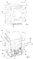
- Landry dryer 1 comprises an outer box casing or cabinet 2, preferably but not necessarily parallelepiped-shaped, and a drying chamber, such as a drum 3, for example having the shape of a hollow cylinder, for housing the laundry and in general the clothes and garments to be dried.
- the drum 3 is preferably rotatably fixed to the cabinet 2. Access to the drum 3 is achieved for example via a door 4, preferably hinged to the cabinet 2, which can open and close an opening 4a realized on the cabinet 2 itself.
- the cabinet 2 generally includes a plurality of walls, i.e. a front wall 20, a rear wall 21 and two sidewalls 25, all mounted between a lower portion or basement 24 and a ceiling or top portion 26.
- the basement 24 is molded via an injection molding process.
- the door 4 is hinged so as to access the drum 3.
- the cabinet 2, with its walls, defines the volume of the laundry dryer 1.
- the basement 24 rests on a floor and its vertical distance from the floor may be advantageously adjusted through regulating feet 46 provided on the lower surface of the basement 24 facing the floor.
- the laundry dryer 1, and in particular the basement 24, defines an horizontal plane (X, Y) which is substantial the plane of the ground on which the laundry dryer 1 is positioned, thus it is considered to be substantially horizontal, and a vertical direction Z perpendicular to the plane (X, Y).
- the laundry dryer 1 also preferably comprises an electrically-powered motor assembly 5 structured for driving into rotation, on command, the drum 3 about its axis inside the cabinet 2.
- the door 4 and the electrically-powered motor assembly 5 are common parts in the technical field and are considered to be known; therefore they will not be described in detail.
- the laundry dryer 1 also preferably comprises an open-circuit or closed-circuit, hot-air generator 6, which is structured to circulate through the drum 3 a stream of hot air having a low moisture level, and which flows over and dries the laundry located inside the drum 3.
- the hot-air generator 6 is a common part in the technical field and is considered to be known; therefore, it will not be described in detail.
- the laundry dryer 1 may include a control unit (not shown) which controls both the electrically-powered motor assembly 5 and the hot-air generator 6 of the laundry dryer 1 to perform, on command, one of the user-selectable drying cycles preferably stored in the same central control unit.
- the programs as well as other parameters of the laundry dryer 1, or alarm and warning functions can be set and/or visualized in a control panel 11, preferably realized in a top portion of the laundry dryer 1, such as above the door 4.
- the drum 3 includes a mantle, having preferably a substantial cylindrical, tubular body 3c, which is preferably made of metal material and is arranged inside the cabinet 2 and is apt to rotate around a general rotational axis R which can be horizontal, i.e. parallel to the (X, Y) plane, or tilted with respect to the latter.
- a general rotational axis R which can be horizontal, i.e. parallel to the (X, Y) plane, or tilted with respect to the latter.
- the cylindrical mantle 3c defines a first end 3a and a second end 3b and the drum 3 is so arranged that the first end 3a (including a circular front rim 3f) of the mantle 3c is faced to the laundry loading/unloading opening 4a realized on the front wall 20 of the cabinet 2 and the door 4, while the second end 3b has also a rim 3e which shows preferably a circular shape.
- the second or rear end 3b of the drum 3 (including the rim 3e) is closed by a back or flange wall 8.
- the drum back wall 8 is faced to the rear wall 21 of the cabinet 2 and is permanently and rigidly coupled to the second end 3b of the mantle 3c of the drum 3 so as to close said second end 3b.
- the back wall 8 forms, together with the mantle 3c, a substantially cylindrical, cup-shaped rigid container structured for housing the laundry to be dried.
- the drum back wall 8 is coupled to the circular rim 3e of the second end 3b of the drum mantle 3c.
- the rotatable drum 3 is formed by two bodies joined together, one of this said two bodies being the mantle 3c and the other of said two bodies being the back wall 8 which is permanently fixed to the rear end 3b of the mantle 3c and rotates with the latter when the drum 3 rotates.
- the back wall 8 is furthermore suitably perforated so as to allow a stream of drying air to flow through the back wall 8 of the drum 3.
- the perforated portion of the back wall 8 is located approximately at the center of the back wall 8 so as to be substantially coaxial to the longitudinal reference axis R of the rotatable drum 3, and is preferably substantially circular in shape.
- the remaining portion of the back wall 8, including an outer rim 8a thereof, is not perforated. Perforations in the back wall 8 will be called, in the following, vents 9.
- the drum 3 further comprises a first region 33 having a first strength and a second region 34 having a second strength which is lower than the first strength, the function of which will be clearer in the following of the present detailed description.
- the first region 33 of the drum 3 is the one formed at the coupling zone between the circular rim 3e of the second end 3b of the mantle 3c and the back wall 8 of the drum 3, whereas the second region 34 of the drum 3 corresponds to other parts of the drum 3, for example the mantle 3a, the mantle first end 3a or the mantle second end 3b.
- the first region 33 has a thickness of about 2.2 mm
- the second region 34 has a thickness of about 0,6 mm.
- the first region 33 having a higher strength consists of a plurality of grooves (not shown), preferably circular grooves, formed at an outer surface of the drum 3.
- the front wall 20 is preferably coupled to the basement 24 and includes a front bulkhead (not shown), preferably made of plastic material, where the opening 4a of the door 4 is realized and to which the drum 3 is coupled for rotation.
- the front bulkhead is preferably covered by a panel extending around the opening 4a and defining the external front surface of the front wall 20 of the cabinet 2.
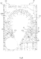
- the rear wall 21 of the cabinet 21 includes a supporting panel or rear bulkhead 210.
- the back wall 8 of the drum 3 substantially faces the rear bulkhead 210, which is preferably made of plastic material, and is coupled in preferably substantially airtight and axially rotating manner to such rear bulkhead 210 with the interposition of a second circular sealing gasket 32.
- Front circular sealing gasket (not shown) and rear circular sealing gasket 32 are preferably substantially coaxial to the longitudinal axis R of the drum 3.
- a power cord (not shown in the drawings), provided with a plug, exits from the rear wall 21 of the cabinet 2 through a passage 212 formed in the rear bulkhead 210 and serves for powering the laundry dryer 1 when connected to power mains.
- the rear wall 21 of the cabinet 2 mainly includes two elements, i.e. the rear bulkhead 210 and a cover 213.
- the rear bulkhead 210 includes a first surface 210a facing the interior of the cabinet 2, such as the back wall 8 of the drum 3, and a second surface 210b, facing the exterior or the outside of the cabinet 2.
- the rear bulkhead 210 includes a through drum aperture 214 located in front of the back wall 8 of the drum 3, such that from thus drum aperture 214 the back wall 8 is visible, and a fan housing 215 for housing an impeller (not depicted) of a fan 12 (see Figure 2 ) of the drying process air circuit.
- the cover 213 is coupled to the rear bulkhead 210 in order to close the aperture 214 and the fan housing 215.
- the cover 213 is formed as two separate pieces covering the drum aperture 214 and the fan housing 215, respectively.
- the rear bulkhead 210 includes a circular central bulge for closing the drum aperture and a fan housing closed by a lid.
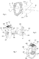
- the drum 3 is preferably structured for being rotatably supported by a drum support assembly, including a plurality of idle rollers 10a, 10b (see Figure 2 ), which are arranged - off-axis with respect to the general rotational axis R of the drum 3 - approximatively at the two axial ends 3a, 3b, with their rotation axis substantially parallel to the general rotational axis R of the drum 3, so as to allow the tubular body of the drum 3 to rotate about the longitudinal reference or general rotational axis R of the drum 3 inside the cabinet 2.
- a drum support assembly including a plurality of idle rollers 10a, 10b (see Figure 2 ), which are arranged - off-axis with respect to the general rotational axis R of the drum 3 - approximatively at the two axial ends 3a, 3b, with their rotation axis substantially parallel to the general rotational axis R of the drum 3, so as to allow the tubular body of the drum 3 to rotate about the longitudinal reference or general rotational
- rollers 10a, 10b are located at the front end 3a of the drum 3 and two other of such rollers 10b are located at the back end 3b of the drum 3, which forms the second region of the drum 3.
- rollers 10a, 10b comprise a plastic, i.e. polymeric, material.
- the two rollers (or more) 10b located at the rear end 3b of the drum 3 are fixed to the rear bulkhead 210, for example they are attached via bosses or pins or brackets 216 to the rear bulkhead 210 and are fixed therein by means of screws or snap-fitting connections (not depicted in the drawings).
- the bosses or brackets 216 are preferably formed as a single unitary piece with the rear bulkhead 210.
- the two rollers (or more) 10a located at the front end 3a of the drum 3 may be either connected to the front bulkhead or they might be connected to the basement 24.
- Figures 4 and 5 shows a variant of the embodiment of Figure 3 .
- the bulkhead 210 is analogous to the embodiment of Figure 3 with the exception of the drum support assembly for the drum 3, as detailed below.
- the drum 3 is supported in rotation by a drum support assembly including two rollers (or more) 10a located at the front end 3a of the drum 3 and a shaft 41 provided at the back wall 8 of the drum 3.
- the shaft 41 is preferably coaxial with the general rotational axis R of the drum 3 and is supported in turn around the rotational axis R at the rear bulkhead 210.
- the shaft 41 is journalled on a bearing portion 43 preferably provided at the rear bulkhead 210.
- the rear bulkhead 210 includes a portion of the drum support assembly including the bearing portion 43, e.g. a plurality of ribs 218, preferably realized integral to the rear bulkhead 210.
- the bearing portion 43 is provided for allowing the drum shaft 41 to rotate around an axis S forming an angle ⁇ with the rotation axis R of the drum 3.
- the laundry dryer 1 further comprises a transportation device 40 configured to be operated for engaging/disengaging the drum 3 to/from the drum support assembly. Disengaging the drum form the drum support assembly is particularly useful and advantageous during transport of the laundry dryer 1, for example from the place of manufacturing to the store or the place of use.
- the transportation device 40 comprises a pair of pin-cam assemblies 410-420, which are arranged - preferably off-axis with respect to the general rotational axis R of the drum 3 - at the rear wall 21 of the cabinet 2. More specifically, the pair of pin-cam assemblies 410-420 are mounted in a rotatable manner on the rear bulkhead 210 of the cabinet 2. A pair of pass-through openings 213 is thus formed in the rear bulkhead 210 for housing a respective pin-cam assembly 410-420 of the transportation device 40. It is understood that any suitable number of pin-cam assemblies can be provided.
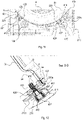
- Each pin-cam assembly of the transportation device 40 comprises a pin member 410 rotatable about a longitudinal axis which extends parallel to the drum rotational axis R, and a cam member 420 associated to the pin member 410 such that a rotation of the pin member 410 about its longitudinal axis causes the cam member 420 to rotate about the pin member longitudinal axis.
- the pin member 410 comprises a head portion 411, a body portion 412, and a tail portion 413.
- the body portion 412 is configured to be housed within the pass-through opening 213 of the rear bulkhead 210; the head portion 411, in the assembled condition of the laundry dryer 1, partially projects from the rear bulkhead second surface 210b, facing the exterior or the outside of the cabinet 2; and the tail portion 414 is configured to be coupled with the cam member 420 in such a way, in the assembled condition of the laundry dryer 1, the cam member 420 projects towards the drum from the rear bulkhead first surface 210a facing the interior of the cabinet 2. In this way, the pin member 410 can be rotated relative to the rear bulkhead 210 acting from the outer side of the laundry dryer.
- a plurality of circular grooves 414 are preferably formed in an outer surface of the head portion 411 of the pin member 410, in order to improve the coupling between the pin member 410 and the pass-through opening 213 of the rear bulkhead 210 by reducing friction.
- the head portion 411 further comprises a lug 415, preferably L-shaped, provided for giving a reference of the pin-member rotational position relative to the rear bulkhead 210.
- icons 230, 231 may be provided on the rear bulkhead second surface 210b, facing the exterior or the outside of the cabinet 2, indicating the enabled/disabled status of the transportation device when the lug 415 is placed in proximity of such icons.
- the head portion 411 of the pin member 410 is hollow and presents a seat 417 for allowing the user to insert an Allen key or similar means for manually disabling/enabling the transportation device 40.
- a plurality of longitudinal flexible hook elements 416 preferably project from the body portion 412 of the pin member 410. These flexible hook elements 416 facilitate mounting operations of the cam member 420 on the pin member 410 and prevent accidental release of such coupling.
- the cam member 420 comprises a body 421, which is preferably substantially elliptically shaped.
- a hub 422 configured to house the tail portion 413 of the pin member 410 is provided in the body 421 and ribs 423 departing from the hub 422 are provided for reinforcing the body structure.
- a support portion 424 is provided on the cam member 420 outer edge and it is suitably configured to contact the drum 3 when the transportation device 40 is placed in the enabled position. More particularly, the support portion 424 of the cam member 420 is configured to contact the higher strength first region 33 of the drum 3, preferably the one formed at the coupling zone between the circular rim 3e of the second end 3b of the mantle 3c and the back wall 8 of the drum 3.
- the support portion 424 of the cam member 420 is preferably knurled, and the cam member 420 further comprises a raiser 425.
- a plurality of flaps 426 is preferably formed in the raiser 425, each flap 426 being configured to match with the knurled support portion 424 in order to advantageously improve the grip between the cam member 420 and the drum 3 when the transportation device 40 is in its enabled position.
- a detent 427 may extend upwardly from the raiser 425 and may be configured to cooperate with a hook 219 provided in the rear bulkhead first surface 210a facing the interior of the cabinet 2 in order to aid to maintain the transportation device in the enabled position thereof in case of fall of the laundry dryer 1.
- hook 219 In the embodiment illustrated, only one hook 219 is provided, but it is to be understood that a pair of hooks 219 can be provided, one for each pin-cam assembly of the transportation device 40.
- a stopper 220 is also formed in a cavity 221 provided in the rear bulkhead first surface 210a facing the interior of the cabinet 2, in order to stop the rotation of each cam member 420 during operation of the transportation device 40 between the enabled position and the disable position.
- Figures 9-10 and 11 show respectively the enabled position and the disabled position of the transportation device 40 for a laundry dryer 1 provided with a drum support assembly of the type shown in Figure 3 , i.e. comprising two (or more) idle rollers 10a located at the front end 3a of the drum 3 and two (or more) idle rollers 10b located at the back end 3b of the drum 3.
- each cam member 420 contacts with a respective portion of the first region 3e of the drum 3 thus raising and separating the drum 3 from the contact with the idle rollers 10a, 10b which support the drum 3 during rotation about its rotational axis R.
- the detent 427 of a cam member 420 engages the hook 219 provided in the rear bulkhead first surface 210a, thereby blocking the cam member 420 in the engaged position.
- each cam member 420 is not into contact with a respective portion of the first region 3e of the drum 3 and the drum 3 is rotatably supported by the idle rollers 10a, 10b. Moreover, if provided, the detent 427 of a cam member 420 is disengaged from the hook 219 provided in the rear bulkhead first surface 210a and each cam member 420 abuts against the respective stopper 221.
- each cam member 420 contacts with a respective portion of the first region 3e of the drum 3 thus separating the drum 3 from the contact with the idle rollers 10a which support the drum 3 during rotation about its rotational axis R.
- the drum shaft 41 rotates around the axis S forming an angle ⁇ with the rotation axis R of the drum 3. If provided, the detent 427 of a cam member 420 engages the hook 219 provided in the rear bulkhead first surface 210a.
- each cam member 420 is not into contact with a respective portion of the first region 3e of the drum 3 and the drum 3 is rotatably supported by the idle rollers 10a. Moreover, if provided, the detent 427 of a cam member 420 is disengaged from the hook 219 provided in the rear bulkhead first surface 210a and each cam member 420 abuts against the respective stopper 221.
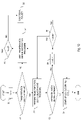
- the method starts at step S0, where the control unit of the laundry dryer 1 is operated to set-up to zero a counter of the disabling attempts N.
- step S0 the method proceeds to step S1, where it is checked whether the transportation device 40 is enabled, i.e. whether the cam member(s) 420 engage the drum 3.
- step S1 comprises checking one or more parameters of the electrically-powered motor assembly 5 driving the drum 3.
- the above one or more parameters comprise electrical parameters, such as current, voltage, power, and frequency of the electrically-powered motor assembly 5 and/or mechanical parameters, such as the rotational speed and the rotor position of the electrically-powered motor assembly 5.
- step S2 a procedure for disabling the transportation device 40 is performed by the control unit.
- the disabling procedure includes rotating the drum 3 to cause the cam member(s) to rotate thereby disengaging the drum 3. Following disengagement, the drum 3 comes into contact with the drum supporting assembly, e.g. the idle rollers 10a,10b.
- the above disabling procedure can be a dedicated procedure, which is carried out before the start of the drying cycle of the laundry dryer 1.
- the disabling procedure can be an initial phase of the drying cycle, during which the drum 3 is operated at a different rotational speed, acceleration and/or direction from those provided for carrying out the drying cycle.
- the drum 3 is operated at a rotational speed lower than that or those used during the drying cycle.
- step S2 the method proceeds to step S3, similar to step S1, where it is further checked whether the transportation device 40 is enabled.
- step S4 the drying cycle is started or continued, based on a dedicated disabling procedure is provided or not.
- step S9 passing through steps S7 and S8, which will be described in detail below.
- step S9 the control unit sends to the user an alarm signal indicating that the transportation device is enabled and/or a signal requiring a manual disabling of the transportation device 40, and then the method ends.
- the user can then disable the transportation device 40, for example by manually rotating the pin-cam assembly with the help of an Allen key or the like.
- the alarm signal can be one of a visual signal, an audio signal, a tactile signal or a combination thereof.
- step S1 if the transportation device 40 is not enabled (NO), or, as cited above, if in step S6 the number N of disabling attempts has reached a threshold value N th (YES), the method skips the disabling procedure in step S7 and proceeds to step S8, where the state of the counter is checked and if the number N of attempts is found to be zero (YES), the method proceeds to step S4, otherwise (NO) the method proceeds to step S9 which has been described above.
- steps S1 and S3 comprise checking if an alarm signal has been sent to the user.
- steps S1 and S3 comprise checking if the transportation device 40 has been manually disabled by the user.
Landscapes
- Engineering & Computer Science (AREA)
- Textile Engineering (AREA)
- Detail Structures Of Washing Machines And Dryers (AREA)
Claims (10)
- Wäschetrockner (1), Folgendes umfassend:- einen Schrank (2),- eine Trommel (3), die drehbar in dem Schrank (2) untergebracht ist;- eine Transportvorrichtung (40), die dem Schrank (2) zugeordnet und dazu ausgelegt ist, zwischen einer aktivierten Stellung, in der die Transportvorrichtung (40) in die Trommel (3) eingreift, und einer deaktivierten Stellung, in der die Transportvorrichtung (40) nicht in die Trommel (3) eingreift, bewegt zu werden;dadurch gekennzeichnet, dassdie Trommel (3) einen ersten Bereich (33, 3e), der eine erste Festigkeit aufweist, und einen zweiten Bereich (34, 3a, 3b, 3c), der eine zweite Festigkeit aufweist, die geringer als die erste Festigkeit ist, umfasst, wobei sich der Begriff Festigkeit auf die Fähigkeit eines Materials bezieht, einer aufgebrachten Beanspruchung standzuhalten, ohne sich zu verformen,und wobei die Transportvorrichtung (40), wenn sie in die aktivierte Stellung gebracht wird, in einen radialen Außenabschnitt des ersten Bereichs (33, 3e) der Trommel (3) eingreift, sodass eine Verformung der Trommel (3) während des Transports des Wäschetrockners (1) und/oder bei einem Sturz des Wäschetrockners (1) verhindert wird.
- Wäschetrockner (1) nach Anspruch 1, wobei der Schrank (2) einen unteren Abschnitt (24), einen Deckenabschnitt (26) und mehrere Wände (20, 21, 25), die zwischen dem unteren Abschnitt (24) und dem Deckenabschnitt (26) um die Trommel (3) herum angeordnet sind, umfasst, wobei die Transportvorrichtung (40) an einer der Wände (20, 21) angeordnet ist, um von einem äußeren Teil des Wäschetrockners (1) zugänglich zu sein.
- Wäschetrockner (1) nach Anspruch 1 oder 2, wobei die Trommel (3) von einer oder mehreren Laufrollen (10a, 10b) getragen wird und die Transportvorrichtung (40), wenn sie in die aktivierte Stellung gebracht wird, die Trommel (3) von der einen oder den mehreren Laufrollen (10a, 10b) trennt, und die Transportvorrichtung (40), wenn sie in die deaktivierte Stellung gebracht wird, zulässt, dass die Trommel (3) in die eine oder mehreren Laufrollen (10a, 10b) eingreift.
- Wäschetrockner (1) nach einem der vorstehenden Ansprüche, wobei die Trommel (3) einen zylindrischen Mantel (3c) mit einem vorderen offenen Ende (3a) zum Be-/Entladen der zu trocknenden Wäsche und ein hinteres Ende (3b), das durch eine Rückwand (8) verschlossen ist, die am Mantel (3c) befestigt ist, um sich damit zu drehen, aufweist, wobei ein Wellenabschnitt (41), der auf einem Lagerabschnitt (43) gelagert ist, an der Rückwand (8) vorgesehen ist, wobei der Lagerabschnitt (43) an einer der Rückwand (8) zugewandten Schrankwand vorgesehen ist und zulässt, dass sich der Wellenabschnitt (41) um eine Achse (S) dreht, die einen Winkel (α) mit der Trommeldrehachse (R) ausbildet, wenn sich die Transportvorrichtung (40) in der aktivierten Stellung befindet.
- Wäschetrockner (1) nach einem der vorstehenden Ansprüche, wobei die Trommel (3) von einer oder mehreren Laufrollen (10a, 10b) getragen wird, die in dem zweiten Bereich (34, 3a, 3b) in die Trommel (3) eingreift/eingreifen.
- Wäschetrockner (1) nach einem der vorstehenden Ansprüche, wobei die Transportvorrichtung (40) mindestens eine Zapfen-Nocken-Anordnung (410, 420) umfasst, die ein Zapfenelement (410) und ein dem Zapfenelement (410) zugeordnetes Nockenelement (420) umfasst, sodass eine Drehung des Zapfenelements (420) um seine Längsachse bewirkt, dass sich das Nockenelement (420) um die Längsachse dreht.
- Wäschetrockner (1) nach Anspruch 6, wobei das Zapfenelement (410) einen Kopfabschnitt (411), der zur Außenseite des Schranks (2) vorsteht, und einen Endabschnitt (413), der zur Innenseite des Schranks (2) vorsteht, umfasst, wobei das Nockenelement (420) dem Endabschnitt (413) des Zapfenelements (410) zugeordnet ist.
- Wäschetrockner (1) nach Anspruch 6 oder 7, wobei sich die Längsachse des Zapfenelements (410) parallel zur Drehachse (R) der Trommel (3) erstreckt.
- Wäschetrockner (1) nach einem der Ansprüche 6 bis 8, wobei das Nockenelement (420) eine Öffnung (422) zur Aufnahme des Endabschnitts (413) des Zapfenelements (410) und einen Trägerabschnitt (424), der den ersten Bereich (33, 3e) der Trommel (3) berührt, wenn die Transportvorrichtung (40) in die aktivierte Stellung gebracht wird, umfasst.
- Wäschetrockner (1) nach einem der vorstehenden Ansprüche, wobei die Trommel (3) von mehreren Laufrollen (10a, 10b) getragen wird und die Transportvorrichtung (40) mehrere Zapfen-Nocken-Anordnungen (410, 420) umfasst, die jeweils in der Nähe einer der mehreren Laufrollen (10a, 10b) vorgesehen sind.
Priority Applications (3)
| Application Number | Priority Date | Filing Date | Title |
|---|---|---|---|
| EP15178431.1A EP3124671B1 (de) | 2015-07-27 | 2015-07-27 | Wäschetrockner |
| PL15178431.1T PL3124671T3 (pl) | 2015-07-27 | 2015-07-27 | Suszarka do prania |
| AU2016206405A AU2016206405B2 (en) | 2015-07-27 | 2016-07-22 | Laundry Dryer |
Applications Claiming Priority (1)
| Application Number | Priority Date | Filing Date | Title |
|---|---|---|---|
| EP15178431.1A EP3124671B1 (de) | 2015-07-27 | 2015-07-27 | Wäschetrockner |
Publications (2)
| Publication Number | Publication Date |
|---|---|
| EP3124671A1 EP3124671A1 (de) | 2017-02-01 |
| EP3124671B1 true EP3124671B1 (de) | 2022-09-07 |
Family
ID=53724101
Family Applications (1)
| Application Number | Title | Priority Date | Filing Date |
|---|---|---|---|
| EP15178431.1A Active EP3124671B1 (de) | 2015-07-27 | 2015-07-27 | Wäschetrockner |
Country Status (3)
| Country | Link |
|---|---|
| EP (1) | EP3124671B1 (de) |
| AU (1) | AU2016206405B2 (de) |
| PL (1) | PL3124671T3 (de) |
Families Citing this family (3)
| Publication number | Priority date | Publication date | Assignee | Title |
|---|---|---|---|---|
| DE102017218361A1 (de) | 2017-10-13 | 2019-04-18 | BSH Hausgeräte GmbH | Trockner mit einer Sicherungsvorrichtung zum Schutz vor Beschädigung bei Stößen sowie Verfahren zu dessen Betrieb |
| CN110409145B (zh) * | 2018-04-28 | 2021-11-02 | 无锡小天鹅电器有限公司 | 衣物处理装置 |
| CN112899983B (zh) * | 2019-12-04 | 2024-05-24 | 青岛海尔洗衣机有限公司 | 具有移动单元的衣物处理设备及其控制方法 |
Family Cites Families (7)
| Publication number | Priority date | Publication date | Assignee | Title |
|---|---|---|---|---|
| GB743031A (en) * | 1953-07-24 | 1956-01-04 | Olof Holger Petterson | Improvements in or relating to machines for treating or washing clothes and the like |
| US3057480A (en) * | 1958-12-18 | 1962-10-09 | Gen Motors Corp | Centrifugal clothes drier |
| DE3739036A1 (de) * | 1987-11-17 | 1989-05-24 | Bosch Siemens Hausgeraete | Elektrisches haushaltgeraet mit einem schrankfoermigen aussengehaeuse |
| CN2934310Y (zh) * | 2006-05-30 | 2007-08-15 | 无锡小天鹅苏泰洗涤机械有限公司 | 洗衣筒固定装置 |
| EP2388366B1 (de) * | 2010-05-21 | 2016-09-28 | Whirlpool Corporation | Trommelwaschmaschine mit einem System zum Befestigen der Wascheinheit während des Transports |
| EP2773806B1 (de) | 2011-11-04 | 2016-02-03 | Arçelik Anonim Sirketi | Wäschetrockner mit transportsicherheitselement |
| DE102012215044A1 (de) * | 2012-08-23 | 2014-02-27 | BSH Bosch und Siemens Hausgeräte GmbH | Einrichtung in einer Waschmaschine zur transportsicheren Festlegung des Trommelaggregats |
-
2015
- 2015-07-27 EP EP15178431.1A patent/EP3124671B1/de active Active
- 2015-07-27 PL PL15178431.1T patent/PL3124671T3/pl unknown
-
2016
- 2016-07-22 AU AU2016206405A patent/AU2016206405B2/en active Active
Also Published As
| Publication number | Publication date |
|---|---|
| PL3124671T3 (pl) | 2023-01-02 |
| AU2016206405A1 (en) | 2017-02-16 |
| EP3124671A1 (de) | 2017-02-01 |
| AU2016206405B2 (en) | 2021-11-18 |
Similar Documents
| Publication | Publication Date | Title |
|---|---|---|
| EP2317001B1 (de) | Haushaltsgerät mit wandbefestigung | |
| KR100925735B1 (ko) | 서포터, 이를 구비한 키높이 수납장 및 의류처리장치 | |
| EP2788539B1 (de) | Filterführung mit einer filterabdeckungs-verriegelungsvorrichtung sowie kleidertrocknungsmaschine damit | |
| EP2317002B1 (de) | Haushaltsgerät zur Wandanbringung | |
| US20080022551A1 (en) | Clothes dryer with extendable rack | |
| EP2476795B1 (de) | Wäschetrockner | |
| EP2990519A1 (de) | Wäschetrockner | |
| EP2990521B1 (de) | Wäschetrockner | |
| EP3124671B1 (de) | Wäschetrockner | |
| JP3801167B2 (ja) | ドラム式洗濯機 | |
| EP3124679B1 (de) | Wäschebehandlungsmaschine | |
| EP2843114B1 (de) | Wäschetrockner mit Drehtrommel | |
| CA2604666A1 (en) | Clothes dryer bulkhead recess | |
| JP2007167263A (ja) | ドラム式洗濯機 | |
| JP2008093245A (ja) | ドラム式洗濯乾燥機 | |
| AU2014314499A1 (en) | Rotary-drum laundry dryer | |
| JP5050177B2 (ja) | ドラム式洗濯機 | |
| AU2016206404B2 (en) | Washing and/or drying appliance | |
| EP2674524B1 (de) | Verbesserte Waschmaschine | |
| EP2631356B1 (de) | Wäschetrockner mit Drehtrommel | |
| EP3730687A1 (de) | Vorrichtung zur behandlung von kleidung | |
| JP2752192B2 (ja) | 洗濯機 | |
| AU2014314501A1 (en) | Rotary-drum laundry dryer | |
| JP2025057909A (ja) | ドラム式洗濯機 | |
| JP2018148967A (ja) | 洗濯乾燥機 |
Legal Events
| Date | Code | Title | Description |
|---|---|---|---|
| PUAI | Public reference made under article 153(3) epc to a published international application that has entered the european phase |
Free format text: ORIGINAL CODE: 0009012 |
|
| STAA | Information on the status of an ep patent application or granted ep patent |
Free format text: STATUS: THE APPLICATION HAS BEEN PUBLISHED |
|
| AK | Designated contracting states |
Kind code of ref document: A1 Designated state(s): AL AT BE BG CH CY CZ DE DK EE ES FI FR GB GR HR HU IE IS IT LI LT LU LV MC MK MT NL NO PL PT RO RS SE SI SK SM TR |
|
| AX | Request for extension of the european patent |
Extension state: BA ME |
|
| RBV | Designated contracting states (corrected) |
Designated state(s): AL AT BE BG CH CY CZ DE DK EE ES FI FR GB GR HR HU IE IS IT LI LT LU LV MC MK MT NL NO PL PT RO RS SE SI SK SM TR |
|
| STAA | Information on the status of an ep patent application or granted ep patent |
Free format text: STATUS: REQUEST FOR EXAMINATION WAS MADE |
|
| 17P | Request for examination filed |
Effective date: 20170803 |
|
| GRAP | Despatch of communication of intention to grant a patent |
Free format text: ORIGINAL CODE: EPIDOSNIGR1 |
|
| STAA | Information on the status of an ep patent application or granted ep patent |
Free format text: STATUS: GRANT OF PATENT IS INTENDED |
|
| INTG | Intention to grant announced |
Effective date: 20220330 |
|
| GRAS | Grant fee paid |
Free format text: ORIGINAL CODE: EPIDOSNIGR3 |
|
| GRAA | (expected) grant |
Free format text: ORIGINAL CODE: 0009210 |
|
| STAA | Information on the status of an ep patent application or granted ep patent |
Free format text: STATUS: THE PATENT HAS BEEN GRANTED |
|
| AK | Designated contracting states |
Kind code of ref document: B1 Designated state(s): AL AT BE BG CH CY CZ DE DK EE ES FI FR GB GR HR HU IE IS IT LI LT LU LV MC MK MT NL NO PL PT RO RS SE SI SK SM TR |
|
| REG | Reference to a national code |
Ref country code: GB Ref legal event code: FG4D |
|
| REG | Reference to a national code |
Ref country code: CH Ref legal event code: EP Ref country code: AT Ref legal event code: REF Ref document number: 1517116 Country of ref document: AT Kind code of ref document: T Effective date: 20220915 |
|
| REG | Reference to a national code |
Ref country code: IE Ref legal event code: FG4D |
|
| REG | Reference to a national code |
Ref country code: DE Ref legal event code: R096 Ref document number: 602015080672 Country of ref document: DE |
|
| REG | Reference to a national code |
Ref country code: LT Ref legal event code: MG9D |
|
| REG | Reference to a national code |
Ref country code: NL Ref legal event code: MP Effective date: 20220907 |
|
| PG25 | Lapsed in a contracting state [announced via postgrant information from national office to epo] |
Ref country code: SE Free format text: LAPSE BECAUSE OF FAILURE TO SUBMIT A TRANSLATION OF THE DESCRIPTION OR TO PAY THE FEE WITHIN THE PRESCRIBED TIME-LIMIT Effective date: 20220907 Ref country code: RS Free format text: LAPSE BECAUSE OF FAILURE TO SUBMIT A TRANSLATION OF THE DESCRIPTION OR TO PAY THE FEE WITHIN THE PRESCRIBED TIME-LIMIT Effective date: 20220907 Ref country code: NO Free format text: LAPSE BECAUSE OF FAILURE TO SUBMIT A TRANSLATION OF THE DESCRIPTION OR TO PAY THE FEE WITHIN THE PRESCRIBED TIME-LIMIT Effective date: 20221207 Ref country code: LV Free format text: LAPSE BECAUSE OF FAILURE TO SUBMIT A TRANSLATION OF THE DESCRIPTION OR TO PAY THE FEE WITHIN THE PRESCRIBED TIME-LIMIT Effective date: 20220907 Ref country code: LT Free format text: LAPSE BECAUSE OF FAILURE TO SUBMIT A TRANSLATION OF THE DESCRIPTION OR TO PAY THE FEE WITHIN THE PRESCRIBED TIME-LIMIT Effective date: 20220907 Ref country code: FI Free format text: LAPSE BECAUSE OF FAILURE TO SUBMIT A TRANSLATION OF THE DESCRIPTION OR TO PAY THE FEE WITHIN THE PRESCRIBED TIME-LIMIT Effective date: 20220907 Ref country code: ES Free format text: LAPSE BECAUSE OF FAILURE TO SUBMIT A TRANSLATION OF THE DESCRIPTION OR TO PAY THE FEE WITHIN THE PRESCRIBED TIME-LIMIT Effective date: 20220907 |
|
| REG | Reference to a national code |
Ref country code: AT Ref legal event code: MK05 Ref document number: 1517116 Country of ref document: AT Kind code of ref document: T Effective date: 20220907 |
|
| PG25 | Lapsed in a contracting state [announced via postgrant information from national office to epo] |
Ref country code: HR Free format text: LAPSE BECAUSE OF FAILURE TO SUBMIT A TRANSLATION OF THE DESCRIPTION OR TO PAY THE FEE WITHIN THE PRESCRIBED TIME-LIMIT Effective date: 20220907 Ref country code: GR Free format text: LAPSE BECAUSE OF FAILURE TO SUBMIT A TRANSLATION OF THE DESCRIPTION OR TO PAY THE FEE WITHIN THE PRESCRIBED TIME-LIMIT Effective date: 20221208 |
|
| PG25 | Lapsed in a contracting state [announced via postgrant information from national office to epo] |
Ref country code: SM Free format text: LAPSE BECAUSE OF FAILURE TO SUBMIT A TRANSLATION OF THE DESCRIPTION OR TO PAY THE FEE WITHIN THE PRESCRIBED TIME-LIMIT Effective date: 20220907 Ref country code: RO Free format text: LAPSE BECAUSE OF FAILURE TO SUBMIT A TRANSLATION OF THE DESCRIPTION OR TO PAY THE FEE WITHIN THE PRESCRIBED TIME-LIMIT Effective date: 20220907 Ref country code: PT Free format text: LAPSE BECAUSE OF FAILURE TO SUBMIT A TRANSLATION OF THE DESCRIPTION OR TO PAY THE FEE WITHIN THE PRESCRIBED TIME-LIMIT Effective date: 20230109 Ref country code: CZ Free format text: LAPSE BECAUSE OF FAILURE TO SUBMIT A TRANSLATION OF THE DESCRIPTION OR TO PAY THE FEE WITHIN THE PRESCRIBED TIME-LIMIT Effective date: 20220907 Ref country code: AT Free format text: LAPSE BECAUSE OF FAILURE TO SUBMIT A TRANSLATION OF THE DESCRIPTION OR TO PAY THE FEE WITHIN THE PRESCRIBED TIME-LIMIT Effective date: 20220907 |
|
| PG25 | Lapsed in a contracting state [announced via postgrant information from national office to epo] |
Ref country code: SK Free format text: LAPSE BECAUSE OF FAILURE TO SUBMIT A TRANSLATION OF THE DESCRIPTION OR TO PAY THE FEE WITHIN THE PRESCRIBED TIME-LIMIT Effective date: 20220907 Ref country code: IS Free format text: LAPSE BECAUSE OF FAILURE TO SUBMIT A TRANSLATION OF THE DESCRIPTION OR TO PAY THE FEE WITHIN THE PRESCRIBED TIME-LIMIT Effective date: 20230107 Ref country code: EE Free format text: LAPSE BECAUSE OF FAILURE TO SUBMIT A TRANSLATION OF THE DESCRIPTION OR TO PAY THE FEE WITHIN THE PRESCRIBED TIME-LIMIT Effective date: 20220907 |
|
| REG | Reference to a national code |
Ref country code: DE Ref legal event code: R097 Ref document number: 602015080672 Country of ref document: DE |
|
| PG25 | Lapsed in a contracting state [announced via postgrant information from national office to epo] |
Ref country code: NL Free format text: LAPSE BECAUSE OF FAILURE TO SUBMIT A TRANSLATION OF THE DESCRIPTION OR TO PAY THE FEE WITHIN THE PRESCRIBED TIME-LIMIT Effective date: 20220907 Ref country code: AL Free format text: LAPSE BECAUSE OF FAILURE TO SUBMIT A TRANSLATION OF THE DESCRIPTION OR TO PAY THE FEE WITHIN THE PRESCRIBED TIME-LIMIT Effective date: 20220907 |
|
| PLBE | No opposition filed within time limit |
Free format text: ORIGINAL CODE: 0009261 |
|
| STAA | Information on the status of an ep patent application or granted ep patent |
Free format text: STATUS: NO OPPOSITION FILED WITHIN TIME LIMIT |
|
| PG25 | Lapsed in a contracting state [announced via postgrant information from national office to epo] |
Ref country code: DK Free format text: LAPSE BECAUSE OF FAILURE TO SUBMIT A TRANSLATION OF THE DESCRIPTION OR TO PAY THE FEE WITHIN THE PRESCRIBED TIME-LIMIT Effective date: 20220907 |
|
| P01 | Opt-out of the competence of the unified patent court (upc) registered |
Effective date: 20230625 |
|
| 26N | No opposition filed |
Effective date: 20230608 |
|
| PG25 | Lapsed in a contracting state [announced via postgrant information from national office to epo] |
Ref country code: SI Free format text: LAPSE BECAUSE OF FAILURE TO SUBMIT A TRANSLATION OF THE DESCRIPTION OR TO PAY THE FEE WITHIN THE PRESCRIBED TIME-LIMIT Effective date: 20220907 |
|
| PG25 | Lapsed in a contracting state [announced via postgrant information from national office to epo] |
Ref country code: MC Free format text: LAPSE BECAUSE OF FAILURE TO SUBMIT A TRANSLATION OF THE DESCRIPTION OR TO PAY THE FEE WITHIN THE PRESCRIBED TIME-LIMIT Effective date: 20220907 |
|
| PG25 | Lapsed in a contracting state [announced via postgrant information from national office to epo] |
Ref country code: MC Free format text: LAPSE BECAUSE OF FAILURE TO SUBMIT A TRANSLATION OF THE DESCRIPTION OR TO PAY THE FEE WITHIN THE PRESCRIBED TIME-LIMIT Effective date: 20220907 |
|
| REG | Reference to a national code |
Ref country code: CH Ref legal event code: PL |
|
| REG | Reference to a national code |
Ref country code: BE Ref legal event code: MM Effective date: 20230731 |
|
| PG25 | Lapsed in a contracting state [announced via postgrant information from national office to epo] |
Ref country code: LU Free format text: LAPSE BECAUSE OF NON-PAYMENT OF DUE FEES Effective date: 20230727 |
|
| PG25 | Lapsed in a contracting state [announced via postgrant information from national office to epo] |
Ref country code: LU Free format text: LAPSE BECAUSE OF NON-PAYMENT OF DUE FEES Effective date: 20230727 |
|
| REG | Reference to a national code |
Ref country code: IE Ref legal event code: MM4A |
|
| PG25 | Lapsed in a contracting state [announced via postgrant information from national office to epo] |
Ref country code: CH Free format text: LAPSE BECAUSE OF NON-PAYMENT OF DUE FEES Effective date: 20230731 |
|
| PG25 | Lapsed in a contracting state [announced via postgrant information from national office to epo] |
Ref country code: FR Free format text: LAPSE BECAUSE OF NON-PAYMENT OF DUE FEES Effective date: 20230731 Ref country code: BE Free format text: LAPSE BECAUSE OF NON-PAYMENT OF DUE FEES Effective date: 20230731 |
|
| PG25 | Lapsed in a contracting state [announced via postgrant information from national office to epo] |
Ref country code: IE Free format text: LAPSE BECAUSE OF NON-PAYMENT OF DUE FEES Effective date: 20230727 |
|
| PG25 | Lapsed in a contracting state [announced via postgrant information from national office to epo] |
Ref country code: IE Free format text: LAPSE BECAUSE OF NON-PAYMENT OF DUE FEES Effective date: 20230727 |
|
| PG25 | Lapsed in a contracting state [announced via postgrant information from national office to epo] |
Ref country code: BG Free format text: LAPSE BECAUSE OF FAILURE TO SUBMIT A TRANSLATION OF THE DESCRIPTION OR TO PAY THE FEE WITHIN THE PRESCRIBED TIME-LIMIT Effective date: 20220907 |
|
| PG25 | Lapsed in a contracting state [announced via postgrant information from national office to epo] |
Ref country code: BG Free format text: LAPSE BECAUSE OF FAILURE TO SUBMIT A TRANSLATION OF THE DESCRIPTION OR TO PAY THE FEE WITHIN THE PRESCRIBED TIME-LIMIT Effective date: 20220907 |
|
| PG25 | Lapsed in a contracting state [announced via postgrant information from national office to epo] |
Ref country code: CY Free format text: LAPSE BECAUSE OF FAILURE TO SUBMIT A TRANSLATION OF THE DESCRIPTION OR TO PAY THE FEE WITHIN THE PRESCRIBED TIME-LIMIT; INVALID AB INITIO Effective date: 20150727 |
|
| PG25 | Lapsed in a contracting state [announced via postgrant information from national office to epo] |
Ref country code: HU Free format text: LAPSE BECAUSE OF FAILURE TO SUBMIT A TRANSLATION OF THE DESCRIPTION OR TO PAY THE FEE WITHIN THE PRESCRIBED TIME-LIMIT; INVALID AB INITIO Effective date: 20150727 |
|
| PGFP | Annual fee paid to national office [announced via postgrant information from national office to epo] |
Ref country code: DE Payment date: 20250728 Year of fee payment: 11 |
|
| PGFP | Annual fee paid to national office [announced via postgrant information from national office to epo] |
Ref country code: IT Payment date: 20250721 Year of fee payment: 11 Ref country code: PL Payment date: 20250717 Year of fee payment: 11 |
|
| PGFP | Annual fee paid to national office [announced via postgrant information from national office to epo] |
Ref country code: GB Payment date: 20250722 Year of fee payment: 11 |
|
| PG25 | Lapsed in a contracting state [announced via postgrant information from national office to epo] |
Ref country code: TR Free format text: LAPSE BECAUSE OF FAILURE TO SUBMIT A TRANSLATION OF THE DESCRIPTION OR TO PAY THE FEE WITHIN THE PRESCRIBED TIME-LIMIT Effective date: 20220907 |