EP3124002B1 - Assistance robot - Google Patents
Assistance robot Download PDFInfo
- Publication number
- EP3124002B1 EP3124002B1 EP14887502.4A EP14887502A EP3124002B1 EP 3124002 B1 EP3124002 B1 EP 3124002B1 EP 14887502 A EP14887502 A EP 14887502A EP 3124002 B1 EP3124002 B1 EP 3124002B1
- Authority
- EP
- European Patent Office
- Prior art keywords
- lifting
- lowering
- section
- sections
- holding section
- Prior art date
- Legal status (The legal status is an assumption and is not a legal conclusion. Google has not performed a legal analysis and makes no representation as to the accuracy of the status listed.)
- Active
Links
- 230000010355 oscillation Effects 0.000 description 26
- 230000007246 mechanism Effects 0.000 description 19
- 210000001015 abdomen Anatomy 0.000 description 3
- 230000008878 coupling Effects 0.000 description 3
- 238000010168 coupling process Methods 0.000 description 3
- 238000005859 coupling reaction Methods 0.000 description 3
- 230000007423 decrease Effects 0.000 description 2
- 230000015572 biosynthetic process Effects 0.000 description 1
- 230000008602 contraction Effects 0.000 description 1
- 238000010586 diagram Methods 0.000 description 1
- 230000000694 effects Effects 0.000 description 1
- 230000002349 favourable effect Effects 0.000 description 1
Images


Classifications
-
- A—HUMAN NECESSITIES
- A61—MEDICAL OR VETERINARY SCIENCE; HYGIENE
- A61H—PHYSICAL THERAPY APPARATUS, e.g. DEVICES FOR LOCATING OR STIMULATING REFLEX POINTS IN THE BODY; ARTIFICIAL RESPIRATION; MASSAGE; BATHING DEVICES FOR SPECIAL THERAPEUTIC OR HYGIENIC PURPOSES OR SPECIFIC PARTS OF THE BODY
- A61H3/00—Appliances for aiding patients or disabled persons to walk about
- A61H3/04—Wheeled walking aids for patients or disabled persons
-
- A—HUMAN NECESSITIES
- A61—MEDICAL OR VETERINARY SCIENCE; HYGIENE
- A61G—TRANSPORT, PERSONAL CONVEYANCES, OR ACCOMMODATION SPECIALLY ADAPTED FOR PATIENTS OR DISABLED PERSONS; OPERATING TABLES OR CHAIRS; CHAIRS FOR DENTISTRY; FUNERAL DEVICES
- A61G5/00—Chairs or personal conveyances specially adapted for patients or disabled persons, e.g. wheelchairs
- A61G5/10—Parts, details or accessories
- A61G5/14—Standing-up or sitting-down aids
-
- A—HUMAN NECESSITIES
- A61—MEDICAL OR VETERINARY SCIENCE; HYGIENE
- A61G—TRANSPORT, PERSONAL CONVEYANCES, OR ACCOMMODATION SPECIALLY ADAPTED FOR PATIENTS OR DISABLED PERSONS; OPERATING TABLES OR CHAIRS; CHAIRS FOR DENTISTRY; FUNERAL DEVICES
- A61G7/00—Beds specially adapted for nursing; Devices for lifting patients or disabled persons
- A61G7/10—Devices for lifting patients or disabled persons, e.g. special adaptations of hoists thereto
- A61G7/1013—Lifting of patients by
- A61G7/1019—Vertical extending columns or mechanisms
-
- A—HUMAN NECESSITIES
- A61—MEDICAL OR VETERINARY SCIENCE; HYGIENE
- A61G—TRANSPORT, PERSONAL CONVEYANCES, OR ACCOMMODATION SPECIALLY ADAPTED FOR PATIENTS OR DISABLED PERSONS; OPERATING TABLES OR CHAIRS; CHAIRS FOR DENTISTRY; FUNERAL DEVICES
- A61G7/00—Beds specially adapted for nursing; Devices for lifting patients or disabled persons
- A61G7/10—Devices for lifting patients or disabled persons, e.g. special adaptations of hoists thereto
- A61G7/1073—Parts, details or accessories
- A61G7/1082—Rests specially adapted for
- A61G7/1086—Upper body
-
- A—HUMAN NECESSITIES
- A61—MEDICAL OR VETERINARY SCIENCE; HYGIENE
- A61G—TRANSPORT, PERSONAL CONVEYANCES, OR ACCOMMODATION SPECIALLY ADAPTED FOR PATIENTS OR DISABLED PERSONS; OPERATING TABLES OR CHAIRS; CHAIRS FOR DENTISTRY; FUNERAL DEVICES
- A61G7/00—Beds specially adapted for nursing; Devices for lifting patients or disabled persons
- A61G7/10—Devices for lifting patients or disabled persons, e.g. special adaptations of hoists thereto
- A61G7/104—Devices carried or supported by
- A61G7/1046—Mobile bases, e.g. having wheels
-
- A—HUMAN NECESSITIES
- A61—MEDICAL OR VETERINARY SCIENCE; HYGIENE
- A61G—TRANSPORT, PERSONAL CONVEYANCES, OR ACCOMMODATION SPECIALLY ADAPTED FOR PATIENTS OR DISABLED PERSONS; OPERATING TABLES OR CHAIRS; CHAIRS FOR DENTISTRY; FUNERAL DEVICES
- A61G7/00—Beds specially adapted for nursing; Devices for lifting patients or disabled persons
- A61G7/10—Devices for lifting patients or disabled persons, e.g. special adaptations of hoists thereto
- A61G7/1073—Parts, details or accessories
- A61G7/1082—Rests specially adapted for
- A61G7/1092—Rests specially adapted for the arms
-
- A—HUMAN NECESSITIES
- A61—MEDICAL OR VETERINARY SCIENCE; HYGIENE
- A61H—PHYSICAL THERAPY APPARATUS, e.g. DEVICES FOR LOCATING OR STIMULATING REFLEX POINTS IN THE BODY; ARTIFICIAL RESPIRATION; MASSAGE; BATHING DEVICES FOR SPECIAL THERAPEUTIC OR HYGIENIC PURPOSES OR SPECIFIC PARTS OF THE BODY
- A61H3/00—Appliances for aiding patients or disabled persons to walk about
- A61H3/04—Wheeled walking aids for patients or disabled persons
- A61H2003/043—Wheeled walking aids for patients or disabled persons with a drive mechanism
-
- A—HUMAN NECESSITIES
- A61—MEDICAL OR VETERINARY SCIENCE; HYGIENE
- A61H—PHYSICAL THERAPY APPARATUS, e.g. DEVICES FOR LOCATING OR STIMULATING REFLEX POINTS IN THE BODY; ARTIFICIAL RESPIRATION; MASSAGE; BATHING DEVICES FOR SPECIAL THERAPEUTIC OR HYGIENIC PURPOSES OR SPECIFIC PARTS OF THE BODY
- A61H3/00—Appliances for aiding patients or disabled persons to walk about
- A61H3/04—Wheeled walking aids for patients or disabled persons
- A61H2003/046—Wheeled walking aids for patients or disabled persons with braking means
-
- A—HUMAN NECESSITIES
- A61—MEDICAL OR VETERINARY SCIENCE; HYGIENE
- A61H—PHYSICAL THERAPY APPARATUS, e.g. DEVICES FOR LOCATING OR STIMULATING REFLEX POINTS IN THE BODY; ARTIFICIAL RESPIRATION; MASSAGE; BATHING DEVICES FOR SPECIAL THERAPEUTIC OR HYGIENIC PURPOSES OR SPECIFIC PARTS OF THE BODY
- A61H2201/00—Characteristics of apparatus not provided for in the preceding codes
- A61H2201/50—Control means thereof
- A61H2201/5007—Control means thereof computer controlled
-
- A—HUMAN NECESSITIES
- A61—MEDICAL OR VETERINARY SCIENCE; HYGIENE
- A61H—PHYSICAL THERAPY APPARATUS, e.g. DEVICES FOR LOCATING OR STIMULATING REFLEX POINTS IN THE BODY; ARTIFICIAL RESPIRATION; MASSAGE; BATHING DEVICES FOR SPECIAL THERAPEUTIC OR HYGIENIC PURPOSES OR SPECIFIC PARTS OF THE BODY
- A61H2201/00—Characteristics of apparatus not provided for in the preceding codes
- A61H2201/50—Control means thereof
- A61H2201/5023—Interfaces to the user
- A61H2201/5025—Activation means
- A61H2201/5028—Contact activation, i.e. activated at contact with a surface of the user to be treated
-
- A—HUMAN NECESSITIES
- A61—MEDICAL OR VETERINARY SCIENCE; HYGIENE
- A61H—PHYSICAL THERAPY APPARATUS, e.g. DEVICES FOR LOCATING OR STIMULATING REFLEX POINTS IN THE BODY; ARTIFICIAL RESPIRATION; MASSAGE; BATHING DEVICES FOR SPECIAL THERAPEUTIC OR HYGIENIC PURPOSES OR SPECIFIC PARTS OF THE BODY
- A61H2201/00—Characteristics of apparatus not provided for in the preceding codes
- A61H2201/50—Control means thereof
- A61H2201/5023—Interfaces to the user
- A61H2201/5043—Displays
-
- A—HUMAN NECESSITIES
- A61—MEDICAL OR VETERINARY SCIENCE; HYGIENE
- A61H—PHYSICAL THERAPY APPARATUS, e.g. DEVICES FOR LOCATING OR STIMULATING REFLEX POINTS IN THE BODY; ARTIFICIAL RESPIRATION; MASSAGE; BATHING DEVICES FOR SPECIAL THERAPEUTIC OR HYGIENIC PURPOSES OR SPECIFIC PARTS OF THE BODY
- A61H2201/00—Characteristics of apparatus not provided for in the preceding codes
- A61H2201/50—Control means thereof
- A61H2201/5058—Sensors or detectors
- A61H2201/5061—Force sensors
-
- A—HUMAN NECESSITIES
- A61—MEDICAL OR VETERINARY SCIENCE; HYGIENE
- A61H—PHYSICAL THERAPY APPARATUS, e.g. DEVICES FOR LOCATING OR STIMULATING REFLEX POINTS IN THE BODY; ARTIFICIAL RESPIRATION; MASSAGE; BATHING DEVICES FOR SPECIAL THERAPEUTIC OR HYGIENIC PURPOSES OR SPECIFIC PARTS OF THE BODY
- A61H2201/00—Characteristics of apparatus not provided for in the preceding codes
- A61H2201/50—Control means thereof
- A61H2201/5058—Sensors or detectors
- A61H2201/5069—Angle sensors
Definitions
- the present invention relates to an assistant robot that assists the standing action of a person in need of assistance.
- PTL 1 describes an assistant robot that assists the standing action of a person in need of assistance.
- the assistant robot includes an arm section including multiple joints in order to enable the holding section which holds the person in need of assistance to lift and lower and move in a forward, backward, and inclined manner with respect to a base.
- the arm section includes a first joint that moves a first arm section in an inclined manner with respect to the base, a second joint that slides a second arm section with respect to the first arm section, and a third joint that moves the holding section in an inclined manner with respect to the second arm section.
- a similar assistant robot is disclosed in PTL 2.
- the first joint that moves the first arm section in an inclined manner with respect to the base is located at a location away from the holding section, and thus the moment generated due to the force that the holding section receives from the person in need of assistance becomes extremely great. Therefore, the size of an actuator for driving the first joint becomes large. That is, the size of the assistant robot becomes large as a whole.
- An object of the present invention as defined by the appended claims is to provide an assistant robot in which a small-size actuator can be used.
- An assistant robot includes a base, a lifting and lowering section which lifts and lowers with respect to the base, a holding section which holds a part of a body of a person in need of assistance and moves in a forward, backward, and inclined manner with respect to the lifting and lowering section, a lifting and lowering actuator which drives the lifting and lowering section to lift and lower with respect to the base, and a forward-and-backward movement actuator that drives the holding section in a forward, backward, and inclined manner with respect to the lifting and lowering section.
- One of the lifting and lowering section and the holding section includes a guide path which is formed to extend in a forward-and-backward direction and guides the holding section to move in a forward, backward, and inclined manner with respect to the lifting and lowering section, and the other of the lifting and lowering section and the holding section includes a guided member which moves along the guide path.
- the holding section moves in a forward, backward, and inclined manner with respect to the lifting and lowering section.
- the forward-and-backward movement actuator drives the holding section to move in a forward, backward, and inclined manner with respect to the lifting and lowering section. Therefore, the person in need of assistance is moved in a forward, backward, and inclined manner by the driving of the forward-and-backward movement actuator.
- the forward-and-backward movement actuator drives the holding section with respect to the lifting and lowering section. That is, compared with actuator of the related art which moment-drive the lifting and lowering section with respect to the base, the forward-and-backward movement actuator in the present invention have small size.
- the overall constitution of an assistant robot 1 of a first embodiment will be described with reference to Figs. 1 to 5 .
- the assistant robot 1 supports a part (for example, the upper body) of the body of a person in need of assistance M1 (illustrated in Figs. 13 and 14 ) and assists standing actions and seating actions.
- the assistant robot 1 includes a base 10, lifting and lowering arms 20 and 30, lifting and lowering sections 40, a holding section 50, lifting and lowering actuators 70 and 80, forward-and-backward movement actuators 90 and 100, and a control device 120.
- each of front, back, left, and right is set to be front, back, left, and right when the travelling direction of the assistant robot 1 is considered as forward.
- the base 10 is a portion that is placed on the ground. As illustrated in Fig. 2 , the base 10 is formed in a U shape so as to be open backwards when seen in a plan.
- the base 10 includes four wheels 15 to 18 and is capable of moving forwards and backwards.
- the lifting and lowering arms 20 and 30 are respectively provided on the right and left ends of the upper surface of the base 10 and are provided so as to be capable of stretching upwards. As illustrated in Figs. 1 and 5 , the lifting and lowering arms 20 and 30 linearly stretch and contract in a direction in which the upper end is inclined forwards with respect to the lower end.
- the lifting and lowering sections 40 are provided on the upper ends of the lifting and lowering arms 20 and 30. When the lifting and lowering arms 20 and 30 stretch and contract in the vertical direction, the lifting and lowering sections 40 lift and lower with respect to the base 10. That is, as illustrated in Figs. 1 and 5 , the lifting and lowering sections 40 linearly move forwards as the lifting and lowering sections lift with respect to the base 10.
- the holding section 50 is located on the upper sides of the lifting and lowering sections 40 and is supported by the lifting and lowering sections 40.
- the holding section 50 moves in a forward, backward, and inclined manner with respect to the lifting and lowering sections 40.
- the holding section 50 holds a part of the body of the person in need of assistance M1.
- the holding section 50 includes an attachment 60 that can be exchanged with other attachments depending on the person in need of assistance M1.
- the lifting and lowering actuators 70 and 80 drive the lifting and lowering sections 40 to lift and lower with respect to the base 10.
- the lifting and lowering actuators 70 and 80 respectively drive the extension and contraction of the corresponding lifting and lowering arms 20 and 30. That is, the lifting and lowering sections 40 are driven using the lifting and lowering actuators 70 and 80 to lift and move forwards with respect to the base 10 to a location illustrated in Fig. 5 from a state illustrated in Fig. 1 and vice versa.
- the lifting and lowering actuators 70 and 80 are provided across the base 10 and the lifting and lowering arms 20 and 30.
- the forward-and-backward movement actuators 90 and 100 drive the holding section 50 to move in a forward, backward, and inclined manner with respect to the lifting and lowering sections 40. That is, the holding section 50 is driven using the forward-and-backward movement actuators 90 and 100 to move forwards and be inclined at the front with respect to the lifting and lowering sections 40 to the location illustrated in Fig. 5 from the state illustrated in Fig. 1 and vice versa.
- the forward-and-backward movement actuators 90 and 100 are provided across the lifting and lowering sections 40 and the holding section 50.
- the control device 120 controls the lifting and lowering actuators 70 and 80 and the forward-and-backward movement actuators 90 and 100 in accordance with the operation of the person in need of assistance M1.
- the assistant robot 1 includes a cover 11 for the base 10, covers 25 and 35 for the lifting and lowering arms 20 and 30 respectively, a cover 45 for the lifting and lowering sections 40, and the attachment 60 in the holding section 50. Therefore, the internal constitution of the assistant robot 1 obtained by removing these covers and attachment will be described with reference to Figs. 6 to 8 . However, the lifting and lowering sections 40, the holding section 50, and the forward-and-backward movement actuators 90 and 100 will be described later.
- the base 10 includes right and left frames 12 and 13 and a coupling frame 14 that couples the front end portions of the right and left frames 12 and 13.
- the right and left frames 12 and 13 are disposed at an interval necessary for the person in need of assistance M1 to enter.
- Right and left back wheels 15 and 16 are respectively provided in the back end portions of the right and left frames 12 and 13.
- Right and left front wheels 17 and 18 are respectively provided in the front end portions of the right and left frames 12 and 13.
- the right and left front wheels 17 and 18 revolve in accordance with the travelling direction of the assistant robot 1.
- the right and left back wheels 15 and 16 and the right and left front wheels 17 and 18 are wheels having no driving forces, but the right and left back wheels 15 and 16 and the right and left front wheels 17 and 18 may be driven using a motor or the like.
- the lifting and lowering arms 20 and 30 include first arm sections 21 and 31, second arm sections 22 and 32, and third arm sections 23 and 33.
- the first arm sections 21 and 31, the second arm sections 22 and 32, and the third arm sections 23 and 33 are formed to be long and linear.
- the first arm sections 21 and 31 are respectively fixed to the right and left frames 12 and 13 of the base 10.
- the first arm sections 21 and 31 are fixed to be inclined forwards with respect to the base 10 at a predetermined angle (for example, 80 degrees).
- the second arm sections 22 and 32 slide in the longitudinal direction with respect to the first arm sections 21 and 31.
- the third arm sections 23 and 33 slide in the longitudinal direction with respect to the second arm sections 22 and 32.
- the lifting and lowering sections 40 are fixed to the upper ends of the third arm sections 23 and 33.
- the third arm sections 23 and 33 contract, a majority of the third arm sections 23 and 33 are stored in the second arm sections 22 and 32.
- the lifting and lowering sections 40 are located at the lowermost location.
- the third arm sections 23 and 33 are located at locations above the first arm sections 21 and 31 without overlapping the first arm sections 21 and 31 in the vertical direction as illustrated in Figs. 5 to 8 .
- the lifting and lowering sections 40 are located at the uppermost location.
- the lifting and lowering actuators 70 and 80 include rotary driving sources 71 and 81, first lifting and lowering mechanisms 72 and 82, and second lifting and lowering mechanisms 73 and 83.
- the rotary driving sources 71 and 81 include motors that output rotation driving forces. Appropriately, deceleration mechanisms may be provided in the rotary driving sources 71 and 81.
- the first lifting and lowering mechanisms 72 and 82 are mechanisms which are coupled to the rotary driving sources 71 and 81 and lift and lower the second arm sections 22 and 32 with respect to the first arm sections 21 and 31.
- the first lifting and lowering mechanisms 72 and 82 are screw mechanisms. Meanwhile, as the first lifting and lowering mechanisms 72 and 82, it is possible to apply belt mechanisms.
- the first lifting and lowering mechanisms 72 and 82 include screw shafts 72a and 82a which are rotary-driven using the rotary driving sources 71 and 81 and nut members 72b and 82b. In the present embodiment, the screw shafts 72a and 82a are fixed to the first arm sections 21 and 31, and the nut members 72b and 82b are fixed to the second arm sections 22 and 32.
- the second lifting and lowering mechanisms 73 and 83 are mechanisms that lift and lower the third arm sections 23 and 33 with respect to the second arm sections 22 and 32.
- the second lifting and lowering mechanisms 73 and 83 are belt mechanisms. Meanwhile, as the second lifting and lowering mechanisms 73 and 83, it is possible to apply screw mechanisms.
- the second lifting and lowering mechanisms 73 and 83 include lower pulleys 73a and 83a and upper pulleys 73b and 83b which are provided at both ends of the second arm sections 22 and 32 in the longitudinal direction so as to be capable of rotating.
- the second lifting and lowering mechanisms 73 and 83 include belts 73c and 83c that are suspended at the lower pulleys 73a and 83a and the upper pulleys 73b and 83b.
- the belts 73c and 83c are fixed to upper end coupling members 21a and 31a of the first arm sections 21 and 31 on one side and are fixed to lower end coupling members 23a and 33a of the third arm sections 23 and 33 on the other side. That is, when the second arm sections 22 and 32 lift with respect to the first arm sections 21 and 31, the belts 73c and 83c rotate in synchronization with the lifting action.
- the third arm sections 23 and 33 lift with respect to the second arm sections 22 and 32 in synchronization with the rotating action.
- the lowering action of the second arm sections 22 and 32 and the third arm sections 23 and 33 is an action performed by reversing the above-described action.
- the lifting and lowering sections 40, the holding section 50, and the forward-and-backward movement actuators 90 and 100 will be described with reference to Figs. 9 to 11 .
- a coupled structure between the left side portion of the lifting and lowering section 40 and the left side portion of the holding section 50 will be described. Therefore, the right-side forward-and-backward movement actuator 100 will not be described.
- the coupled structure between the right side portion of the lifting and lowering section 40 and the right side portion of the holding section 50 is a bilaterally symmetric structure of the left-side structure.
- the lifting and lowering sections 40 are fixed to the upper ends of the third arm sections 23.
- the holding section 50 moves in a forward, backward, and inclined manner with respect to the lifting and lowering sections 40.
- the holding section 50 includes guide paths 53 which are rail members, the lifting and lowering sections 40 include guided members 43, screw shafts 93 of the forward-and-backward movement actuators 90 and 100 are provided in the holding section 50, and nut members 94 are provided in the lifting and lowering sections 40.
- the lifting and lowering sections 40 include base sections 41, oscillation support sections 42, and the guided members 43.
- the base sections 41 are formed in a crank shape when seen in the forward-and-backward direction and are fixed to the upper ends of the third arm sections 23 and 33.
- the oscillation support section 42 in the lifting and lowering section 40 is formed in a U shape so as to be open downwards when seen in the forward-and-backward direction and is fixed to one side surface (the right side of Fig. 10 ) of the base section 41.
- the guided member 43 is a member that is held in the guide path 53 described below so as to be capable of moving.
- the guided member 43 has a groove on one side surface and is formed in a block shape.
- the guided member 43 is fixed to the other side surface (the left side in Fig. 10 ) of the base section 41. That is, the base section 41, the oscillation support section 42, and the guided member 43 which constitute the lifting and lowering section 40 are integrally formed.
- the holding section 50 includes a main body frame 51, oscillation support sections 52, and the guide paths 53.
- the main body frame 51 is formed in a U shape so as to be open backwards when seen from above.
- Fig. 9 illustrates an extended portion of the left side of the main body frame 51
- Fig. 10 illustrates a part of the extended portion and the central coupled portion of the main body frame 51.
- the oscillation support section 52 in the holding section 50 is formed in a U shape so as to be open downwards when seen in the forward-and-backward direction.
- the oscillation support section 52 in the holding section 50 is located at a location at which the oscillation support section overlaps the oscillation support sections 42 in the lifting and lowering sections 40 in the forward-and-backward direction and is located ahead of the oscillation support section 42 in the lifting and lowering section 40.
- the guide paths 53 are rail members and are fixed to side surfaces of the right and left extended portions of the main body frame 51.
- the guide path 53 is formed so as to extend in the forward-and-backward direction.
- the guide path 53 is formed in a curved non-linear shape, particularly, an arc shape.
- the guide path 53 is fixed to the main body frame 51 so as to have the front end at the lowest location and have an upward arc shape as illustrated in Fig. 9 .
- the guide path 53 is fitted into the guided member 43 in the vertical direction and holds the guided member 43. That is, the guide path 53 moves the guided member 43 in an arc shape along the guide path 53 as illustrated in Figs. 9 and 11 .
- the main body frame 51 in the holding section 50 moves in a forward, backward, and inclined manner with respect to the lifting and lowering sections 40 as illustrated in Figs. 9 and 11 .
- the main body frame 51 in the holding section 50 moves forwards and is inclined at the front.
- a state in which the locational relationship between the guided members 43 and the guide paths 53 is as illustrated in Fig. 11 transfers to a state illustrated in Fig.
- the main body frame 51 in the holding section 50 moves backwards and falls into a horizontal state.
- the guide paths 53 guide the holding section 50 to move in a forward, backward, and inclined manner with respect to the lifting and lowering sections 40 through the guided members 43.
- the forward-and-backward movement actuators 90 and 100 drive the holding section 50 to move in a forward, backward, and inclined manner with respect to the lifting and lowering sections 40 as described above.
- the number of the forward-and-backward movement actuators is two (the left-side forward-and-backward movement actuator 90 and the right-side forward-and-backward movement actuator 100), but the forward-and-backward movement actuators perform one kind of driving action to drive the holding section 50 with respect to the right and left lifting and lowering sections 40. That is, the two forward-and-backward movement actuators 90 and 100 act in synchronization with each other and are constituted as an actuator that performs one kind of driving action.
- the forward-and-backward movement actuators 90 and 100 that performs one kind of driving action drive the holding section 50 to move in a forward, backward, and inclined manner with respect to the lifting and lowering sections 40 with one kind of driving action.
- the forward-and-backward movement actuator 90 includes the supported member 91, the rotary driving source 92, the screw shaft 93, and the nut member 94.
- the supported member 91 has a through-hole formed in the center and is formed in a block shape.
- the supported member 91 is supported by a U-shaped opening end of the oscillation support section 52 in the holding section 50 so as to be capable of oscillating using the horizontal direction as a rotation axis line.
- the rotary driving source 92 is, for example, a motor.
- the rotary driving source 92 is fixed to the supported member 91. That is, the rotary driving source 92 becomes capable of moving in an inclined manner with respect to the oscillation support section 52 in the holding section 50.
- the screw shaft 93 is coupled to the output axis of the rotary driving source 92 and is rotary-driven using the rotary driving source 92.
- the screw shaft 93 is supported by the supported member 91 so as to be capable of rotating around an axis line of the screw shaft 93. That is, the screw shaft 93 becomes capable of moving in an inclined manner with respect to the oscillation support section 52 together with the rotary driving source 92.
- the nut member 94 is supported by a U-shaped opening end of the oscillation support section 42 in the lifting and lowering section 40 so as to be capable of moving in an inclined manner using the horizontal direction as a rotation axis line.
- the nut member 94 is engaged with the screw shaft 93 and moves along the screw shaft 93 in accordance with the rotation of the screw shaft 93.
- the rotary driving source 92 rotates the screw shaft 93 by means of rotary drive and, furthermore, moves the nut member 94 in the forward-and-backward direction in accordance with the rotation of the screw shaft 93.
- the distance between the supported member 91 that supports one end of the screw shaft 93 and the nut member 94 changes.
- the posture of the holding section 50 with respect to the lifting and lowering sections 40 is determined by the movement of the guided members 43 in an arc shape along the guide paths 53. Therefore, the screw shaft 93 and the nut member 94 move in an inclined manner due to the movement of the holding section 50 with respect to the lifting and lowering sections 40 in a forward, backward, and inclined manner.
- the attachment 60 will be described with reference to Figs. 1 to 4 .
- the attachment 60 includes a main body section 61, a trunk pad 62, right and left grips 63a and 63b, right and left elbow rest sections 64a and 64b, armpit holding sections 65a and 65b, and an operation section 66.
- the main body section 61 is mounted so as to be attachable to or detachable from the main body frame 51 in the holding section 50 (illustrated in Fig. 9 ).
- the trunk pad 62 is formed of a cushion material in an almost plate shape.
- the trunk pad 62 is located in the central portion in the horizontal direction and in the central portion in the forward-and-backward direction of the entire attachment 60 on the upper surface of the main body section 61.
- the trunk pad 62 is provided so that the upper surface thereof is slightly inclined backwards.
- the trunk pad 62 supports almost all of the trunk of the person in need of assistance M1, that is, chest to abdomen and the vicinity of the left armpit to the vicinity of the right armpit.
- the trunk pad 62 is formed to have a narrower horizontal width in the upper half which corresponds to chest than that in the lower half which corresponds to abdomen.
- the person in need of assistance M1 is able to locate both armpits without any discomfort and obtain a feeling of the vicinity of abdomen stably supported.
- the upper edge of the trunk pad 62 is formed in a concave shape so as to allow the head of the person in need of assistance M1 to move without any hindrance.
- the lower edge of the trunk pad 62 is formed in a concave shape so as to allow the leg section to enter the trunk pad and allow the waist portion to be stably supported.
- the grips 63a and 63b are respectively fixed to the front parts of the right and left sides of the main body section 61.
- the elbow rest sections 64a and 64b are respectively disposed in the back of the right and left sides of the main body section 61.
- the operation section 66 includes buttons that the person in need of assistance M1 or a caregiver operates.
- the armpit holding sections 65a and 65b are formed in an arc shape and are respectively disposed on the right and left of the trunk pad 62.
- the armpit holding sections 65a and 65b are pinched under both arms of the person in need of assistance M1 and regulate the forward-and-backward movement of the person in need of assistance M1.
- the operation section 66 includes buttons for lifting and lowering operation.
- the lifting and lowering sections 40 When the person in need of assistance M1 operates the buttons for lifting and lowering operation in the operation section 66, the lifting and lowering sections 40 perform lifting and lowering movement, and the holding section 50 moves in a forward, backward, and inclined manner in synchronization with the lifting and lowering movement of the lifting and lowering sections 40.
- each of the trunk pad 62, the right and left grips 63a and 63b, the right and left elbow rest sections 64a and 64b, the armpit holding sections 65a and 65b, and the operation section 66 can be individually exchanged with new members.
- the attachment 60 does not need to include all of the trunk pad 62, the right and left grips 63a and 63b, the right and left elbow rest sections 64a and 64b, the armpit holding sections 65a and 65b, and the operation section 66 and may have a constitution including only appropriately-selected members.
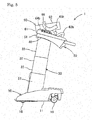
- the constitution of the control device 120 will be described with reference to Fig. 12 . Simultaneously, the actions of the assistant robot 1 will be described with reference to Figs. 13 and 14 .
- the control device 120 includes a calculating section 121 such as CPU and a memory section 122 such as HDD or Flash SSD. Although not illustrated, the control device 120 includes an interface for communication with the operation section 66, the lifting and lowering actuators 70 and 80, and the forward-and-backward movement actuators 90 and 100 as external devices.
- the calculating section 121 acquires operation information from the operation section 66 in a case in which the person in need of assistance M1 operates the operation section 66.
- the operation information is about lifting actions, lowering actions, and stoppage actions with respect to the holding section 50.
- the calculating section 121 acquires the current state information of each of the actuators 70, 80, 90, and 100, for example, the rotation increment values of motors.
- the calculating section 121 synchronously controls the lifting and lowering actuators 70 and 80 and the forward-and-backward movement actuators 90 and 100 on the basis of the acquired operation information, the current states of the respective actuators 70, 80, 90, and 100, and information memorized in the memory section 122.
- the memory section 122 memorizes the operation information, the current states of the respective actuators 70, 80, 90, and 100, and the relationships with command values for the respective actuators 70, 80, 90, and 100.
- the calculating section 121 When the person in need of assistance M1 is in a sitting posture, immediately after the person in need of assistance M1 is held in the trunk pad 62 in the attachment 60 in the holding section 50, the calculating section 121 first drives the forward-and-backward movement actuators 90 and 100 and moves the holding section 50 in a forward, backward, and inclined manner as illustrated in Fig. 13 . After that, the calculating section 121 drives the lifting and lowering actuators 70 and 80 while driving the forward-and-backward movement actuators 90 and 100. That is, the holding section 50 lifts while moving in a forward, backward, and inclined manner as illustrated in Fig. 14 .
- the lift height of the holding section 50 can be set in accordance with the height of the person in need of assistance M1.
- FIG. 15 and 16 illustrate, similar to Figs. 9 and 10 in the first embodiment, a coupled structure between the left side portion of the lifting and lowering section 240 and the left side portion of the holding section 250.
- the holding section 250 includes guide paths 253 which are rail members, the lifting and lowering sections 240 include guided members 243, screw shafts 262 of the forward-and-backward movement actuators 260 are provided in the lifting and lowering sections 240, and nut members 263 are provided in the holding section 250.
- the lifting and lowering sections 240 are mounted on the upper ends of the third arm sections 23.
- the lifting and lowering section 240 includes a base section 241, a both-end support section 242, and a guided member 243.
- the base section 241 is constituted in the same manner as the base section 41 in the first embodiment.
- the both-end support section 242 has flange portions at both ends of a long portion.
- the central portion of the both-end support section 242 is supported by one side surface (the near surface in Fig. 15 ) of the base section 241 so that the both-end support section is capable of moving in an inclined manner around an axial line of the assistant robot 1 in the horizontal direction.
- the guided member 243 is fixed to the other side surface (the far surface in Fig. 15 ) of the base section 241.
- the holding section 250 includes a main body frame 251, oscillation support sections 252, and guide paths 253.
- the oscillation support section 252 is formed in the main body frame 251 in a U shape so as to be open downwards in a case in which the oscillation support section is seen in the forward-and-backward direction.
- the guide paths 253 are rail members and are fixed to side surfaces of the right and left extended portions of the main body frame 251.
- the guide path 253 is formed so as to extend in the forward-and-backward direction.
- the guide path 253 is formed in a curved non-linear shape, particularly, an arc shape.
- the guide path 253 is fitted into the guided member 243 in the vertical direction and holds the guided member 243. That is, the guide path 253 moves the guided member 243 in an arc shape along the guide path 253 as illustrated in Figs. 15 and 16 .
- the forward-and-backward movement actuator 260 includes a rotary driving source 261, a screw shaft 262, and a nut member 263 as illustrated in Figs. 15 and 16 .
- the rotary driving source 261 is fixed to one flange portion of the both-end support section 242 in the lifting and lowering section 240. That is, the rotary driving source 261 becomes capable of moving in an inclined manner with respect to the base section 241 in the lifting and lowering section 240.
- the screw shaft 262 is coupled to the output axis of the rotary driving source 261 and is rotary-driven using the rotary driving source 261.
- the screw shaft 262 has both ends that are supported by the both flange portions of the both-end support section 242 in the lifting and lowering section 240 so that the screw shaft is capable of rotating around the axis line of the screw shaft 262. That is, the screw shaft 262 becomes capable of moving in an inclined manner with respect to the base section 241 in the lifting and lowering section 240 together with the rotary driving source 261.
- the nut member 263 is supported by a U-shaped opening end of the oscillation support section 252 in the holding section 250 so as to be capable of moving in an inclined manner using the horizontal direction as a rotation axis line. The nut member 263 is engaged with the screw shaft 262 and moves along the screw shaft 262 in accordance with the rotation of the screw shaft 262.
- the holding section 250 acts with respect to the lifting and lowering sections 240 in the same manner as in the first embodiment. That is, in a state illustrated in Fig. 15 as the initial state, the rotary driving sources 261 rotary-drive the screw shafts 262 to rotate, and the nut members 263 move in a unidirectional manner along the screw shafts 262 in accordance with the rotation of the screw shafts 262. In such a case, the both-end support sections 242 in the lifting and lowering sections 240 which support the screw shafts 262 and the oscillation support sections 252 in the holding section 250 which support the nut members 263 come close to each other.
- the holding section 250 moves forwards and is inclined at the front with respect to the lifting and lowering sections 240 as illustrated in Fig. 16 .
- the holding section 250 acts with respect to the lifting and lowering sections 240 in a reverse manner.
- FIG. 17 and 18 illustrate, similar to Figs. 9 and 10 in the first embodiment, a coupled structure between the left side portion of the lifting and lowering section 340 and the left side portion of the holding section 350.
- the lifting and lowering sections 340 include guide paths 342 and 343 which are rail members
- the holding section 350 includes guided members 352 and 353
- screw shafts 262 of the forward-and-backward movement actuators 360 are provided in the lifting and lowering sections 340
- nut members 363 are provided in the holding section 250.
- the lifting and lowering sections 340 are mounted on the upper ends of the third arm sections 23.
- the lifting and lowering section 340 includes a base section 341, a first guide path 342, and a second guide path 343.
- the base section 341 is formed to be long in the forward-and-backward direction enough to fix the guide paths 342 and 343 which are rail members.
- the first guide path 342 is formed to be linear and is horizontally disposed in the back part of a side surface of the base section 341 so as to extend in the forward-and-backward direction.
- the second guide path 343 is formed to be linear and is disposed in the front part of the side surface of the base section 341 an angle inclined with respect to the horizontal surface so as to extend in the forward-and-backward direction.
- the second guide path 343 is provided so that the front end is located below the back end.
- the holding section 350 includes a main body frame 351, a first guided member 352, and a second guided member 353 .
- the first guided member 352 is supported by the back part of the main body frame 351 so as to be capable of moving in an inclined manner using the horizontal direction of the assistant robot 300 as a rotation axis line.
- the first guided member 352 is held in the first guide path 342 so as to pinch the first guide path 342 in the lifting and lowering section 340 in the vertical direction.
- the first guided member 352 moves linearly (in the forward-and-backward direction and horizontally) along the first guide path 342.
- the second guided member 353 is supported by the front part of the main body frame 351 so as to be capable of moving in an inclined manner using the horizontal direction as a rotation axis line.
- the second guided member 353 is held in the second guide path 343 so as to pinch the second guide path 343 in the lifting and lowering section 340 in the vertical direction.
- the second guided member 353 moves linearly (in the forward-and-backward direction so as to be inclined at the front) along the second guide path 343.
- the forward-and-backward movement actuator 360 includes a rotary driving source 361, a screw shaft 362, and a nut member 363.
- the rotary driving source 361 is fixed to the base section 341 in the lifting and lowering section 340.
- the screw shaft 362 is coupled to the output axis of the rotary driving source 361 and is rotary-driven using the rotary driving source 361. That is, the rotary driving source 361 and the screw shaft 362 are supported so as to be incapable of moving in an inclined manner with respect to the lifting and lowering section 340.
- the axis line of the screw shaft 362 is horizontally disposed so as to extend in the forward-and-backward direction.
- the nut member 363 is engaged with the screw shaft 362 and moves along the screw shaft 362 in accordance with the rotation of the screw shaft 362.
- the nut member 363 is fixed to the first guided member 352 in the holding section 350. That is, the first guided member 352 in the holding section 350 moves in accordance with the movement of the nut member 363.
- the holding section 350 acts with respect to the lifting and lowering sections 340 in the same manner as in the first embodiment. That is, in a state illustrated in Fig. 17 as the initial state, the rotary driving sources 361 rotary-drive the screw shafts 362 to rotate, and the nut members 363 move forwards along the screw shafts 362 in accordance with the rotation of the screw shafts 362.
- the holding section 350 moves forwards and is inclined at the front with respect to the lifting and lowering sections 340 as illustrated in Fig. 18 .
- the holding section 350 acts with respect to the lifting and lowering sections 340 in a reverse manner.
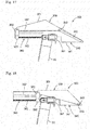
- FIG. 19 and 20 illustrate, similar to Figs. 9 and 10 in the first embodiment, a coupled structure between the left side portion of the lifting and lowering section 440 and the left side portion of the holding section 450.
- the holding section 450 includes guide paths 451a which are grooves
- the lifting and lowering sections 440 include guided members 443 and 444
- main body sections 461 of the forward-and-backward movement actuators 460 are provided in the lifting and lowering sections 440
- rod sections 462 of the forward-and-backward movement actuators 460 are provided in the holding section 450.
- the lifting and lowering sections 440 are mounted on the upper ends of the third arm sections 23.
- the lifting and lowering section 440 includes a base section 441, an oscillation support section 442, a first guided member 443, and a second guided member 444.
- the oscillation support section 442 is provided in the front part of a side surface of the base section 441.
- the first guided member 443 and the second guided member 444 are protruding members that are provided in the back parts of the side surfaces of the base section 441 so as to protrude toward the side parts.
- the first guided member 443 and the second guided member 444 are provided so as to be arranged almost in the forward-and-backward direction.
- the holding section 450 includes a main body frame 451 and oscillation support sections 452.
- the guide paths 451a which are grooves that are open toward the side parts are formed on the side surfaces of the main body frame 451.
- the guide path 451a is formed in a non-linear shape extending in the forward-and-backward direction.
- the front part of the guide path 451a is formed in a linear shape extending in the forward-and-backward direction, and the back part of the guide path 451a is formed in a continuously curved shape in the linear portion.
- the back end of the guide path 451a is located below the front end. That is, the guide path 451a forms a cam groove.
- the first guided member 443 and the second guided member 444 are inserted into the guide path 451a so as to be capable of moving along the guide path 451a.
- the posture of the holding section 450 is stabilized with respect to the lifting and lowering section 440.
- the oscillation support section 452 is provided at the back end of the main body frame 451.
- the forward-and-backward movement actuator 460 is a cylinder mechanism.
- the forward-and-backward movement actuator 460 includes a main body section 461 and a rod section 462.
- the main body section 461 is supported by the oscillation support section 442 in the lifting and lowering section 440 so as to be capable of moving in an inclined manner using the horizontal direction of the assistant robot 400 as a rotation axis line.
- the rod section 462 acts so that the protruding amount changes with respect to the main body section 461.
- the front end of the rod section 462 is supported by the oscillation support section 452 in the holding section 450 so as to be capable of moving in an inclined manner using the horizontal direction of the assistant robot 400 as a rotation axis line.
- the holding section 450 acts with respect to the lifting and lowering sections 440 in the same manner as in the first embodiment. That is, in a state illustrated in Fig. 19 as the initial state, the rod section 462 transfers from a state of being extended with respect to the main body section 461 to a state of being contracted with respect to the main body section, the oscillation support section 452 in the holding section 450 comes close to the oscillation support section 442 in the lifting and lowering section 440. At this time, the first guided member 443 and the second guided member 444 relatively move along the guide path 451a which is a groove. In such a case, as illustrated in Fig. 20 , the holding section 450 is inclined forwards while moving forwards with respect to the lifting and lowering section 440. On the other hand, when the forward-and-backward movement actuators 460 are caused to act in a reverse manner, the holding section 450 acts with respect to the lifting and lowering sections 440 in a reverse manner.
- the guide path 451a is formed in the holding section 450, and the guided members 443 and 444 are provided in the lifting and lowering section 440, but the guide path 451a may be formed in the lifting and lowering section 440, and the guided members 443 and 444 may be provided in the holding section 450.
- the assistant robots 1, 200, 300, and 400 of the first, second, third, and fourth embodiments include the base 10, the lifting and lowering sections 40, 240, 340, and 440 which lift and lower with respect to the base 10, the holding sections 50, 250, 350, and 450 which hold a part of the body of the person in need of assistance M1 and move in a forward, backward, and inclined manner with respect to the lifting and lowering sections 40, 240, 340, and 440, the lifting and lowering actuators 70 and 80 which drive the lifting and lowering sections 40, 240, 340, and 440 to lift and lower with respect to the base 10, and the forward-and-backward movement actuators 90, 100, 260, 360, and 460 which drive the holding sections 50, 250, 350, and 450 to move in a forward, backward, and inclined manner with respect to the lifting and lowering sections 40, 240, 340, and 440.
- One of the lifting and lowering sections 40, 240, 340, and 440 and the holding sections 50, 250, 350, and 450 are formed to extend in the forward-and-backward direction and include the guide paths 53, 253, 342, 343, and 451a which guide the holding sections 50, 250, 350, and 450 to move in a forward, backward, and inclined manner with respect to the lifting and lowering sections 40, 240, 340, and 440.
- the other one of the lifting and lowering sections 40, 240, 340, and 440 and the holding sections 50, 250, 350, and 450 include the guided members 43, 243, 352, 353, 443, and 444 which move along the guide paths 53, 253, 342, 343, and 451a.
- the holding sections 50, 250, 350, and 450 move in a forward, backward, and inclined manner with respect to the lifting and lowering sections 40, 240, 340, and 440.
- the forward-and-backward movement actuators 90, 100, 260, 360, and 460 drive the holding sections 50, 250, 350, and 450 to move in a forward, backward, and inclined manner with respect to the lifting and lowering sections 40, 240, 340, and 440. Therefore, the person in need of assistance M1 is moved in a forward, backward, and inclined manner by the driving of the forward-and-backward movement actuators 90, 100, 260, 360, and 460.
- the forward-and-backward movement actuators 90, 100, 260, 360, and 460 drive the holding sections 50, 250, 350, and 450 with respect to the lifting and lowering sections 40, 240, 340, and 440. That is, compared with actuators in the related art which moment-drive the lifting and lowering sections 50, 250, 350, and 450 with respect to the base 10, the forward-and-backward movement actuators 90, 100, 260, 360, and 460 in the present embodiments have small sizes.
- the forward-and-backward movement actuators 90, 100, 260, 360, and 460 move the holding sections 50, 250, 350, and 450 in an inclined manner and, furthermore, move the holding sections in a forward and backward manner. That is, in the assistant robots 1, 200, 300, and 400, it is not necessary to separately provide actuators for driving the holding sections 50, 250, 350, and 450 to move in an inclined manner and actuators for driving the holding sections in a forward-and-backward manner. Therefore, the number of actuators decreases. As a result, the assistant robots 1, 200, 300, and 400 have small sizes.
- the guide paths 53, 253, 342, and 343 are rail members, and the guided members 43, 243, 352, and 353 are members which are held so as to be capable of relatively moving with respect to the guide paths 53, 253, 342, and 343.
- the holding sections 50, 250, and 350 are stably guided with respect to the lifting and lowering sections 40, 240, and 340.
- the sliding resistance between the guide paths 53, 253, 342, and 343 as rail members and the guided members 43, 243, 352, and 353 is small, and thus the power of the forward-and-backward movement actuators 90, 100, 260, and 360 becomes small.
- the guide path 451a is a groove which is formed in one of the lifting and lowering section 440 and the holding section 450, and the guided members 443 and 444 are protruding members which are inserted into the guide path 451a so as to be capable of relatively moving in the guide path 451a.
- the guide path 451a is not an exclusive member and is formed in one of the lifting and lowering section 440 and the holding section 450, and thus the number of components decreases. Furthermore, since the degree of freedom in designing the shape of the groove is high, the degree of freedom of the holding section 450 acting with respect to the lifting and lowering section 440 is high.
- the holding sections 50, 250, and 450 include the guide paths 53, 253, and 451a
- the lifting and lowering sections 40, 240, and 440 include the guided members 43, 243, 443, and 444. Since the guide paths 53, 253, and 451a have lengths in the forward-and-backward direction, members having the guide paths 53, 253, and 451a have lengths.
- the guided members 43, 243, 443, and 444 are members that move along the guide paths 53, 253, and 451a and are thus relatively short.
- the holding sections 50, 250, and 450 hold a part of the body of a person in need of assistance M1 and thus have a length to a certain extent. Therefore, when the holding sections 50, 250, and 450 having original lengths include the guide paths 53, 253, and 451a, it is possible to shorten the full lengths of the lifting and lowering sections 40, 240, and 440 in the forward-and-backward direction. As a result, the full lengths of the assistant robots 1, 200, and 400 in the forward-and-backward direction become short.
- the forward-and-backward movement actuators 90 and 100 include the rotary driving sources 92 which are provided in the holding section 50, the screw shafts 93 which are coupled to the output axes of the rotary driving sources 92 and are rotary-driven using the rotary driving sources 92, and the nut members 94 which are provided in the lifting and lowering sections 40, are engaged with the screw shafts 93, and move to the screw shafts 93 in accordance with the rotation of the screw shafts 93.
- the screw shafts 93 in the forward-and-backward movement actuators 90 and 100 move together with the holding section 50.
- the screw shafts 93 have lengths.
- the holding section 50 holds a part of the body of the person in need of assistance M1 and thus has a length to a certain extent. Therefore, when the screw shafts 93 are held in the holding section 50 having an original length, it is possible to shorten the lengths in the forward-and-backward direction of members which are provided in the lifting and lowering sections 40. As a result, the full length of the assistant robot 1 in the forward-and-backward direction becomes short.
- the rotary driving sources 92 and the screw shafts 93 are supported by the holding section 50 so as to be capable of moving in an inclined manner
- the nut members 94 are supported by the lifting and lowering sections 40 so as to be capable of moving in an inclined manner.
- the screw shafts 93 move in an inclined manner in accordance with the inclination angle of the holding section 50. Therefore, the sizes of the forward-and-backward movement actuators 90 and 100 in the vertical direction are reduced.
- the forward-and-backward movement actuators 260 and 360 include the rotary driving sources 261 and 361 which are provided in the lifting and lowering sections 240 and 340, the screw shafts 262 and 362 which are coupled to the output axes of the rotary driving sources 261 and 361 and are rotary-driven using the rotary driving sources 261 and 361, and the nut members 63 and 363 which are provided in the holding sections 250 and 350, are engaged with the screw shafts 262 and 362, and move to the screw shafts 262 and 362 in accordance with the rotation of the screw shafts 262 and 362.
- the rotary driving sources 261 and 361 rarely move in a forward and backward manner with respect to the lifting and lowering sections 240 and 340. Therefore, handling of wires for the rotary driving sources 261 and 361 is extremely favorable.
- the rotary driving sources 261 and the screw shafts 262 are supported by the lifting and lowering sections 240 so as to be capable of moving in an inclined manner
- the nut members 263 are supported by the holding sections 250 so as to be capable of moving in an inclined manner.
- the screw shafts 262 move in an inclined manner in accordance with the inclination angle of the holding section 250. Therefore, the sizes of the forward-and-backward movement actuators 260 in the vertical direction are reduced.
- the rotary driving sources 361 and the screw shafts 362 are supported by the lifting and lowering sections 340 so as to be incapable of moving in an inclined manner, and the nut members 363 are supported by the holding sections 350 so as to be capable of moving in an inclined manner.
- the rotary driving sources 361 and the screw shafts 362 move in accordance with the lifting and lowering action of the lifting and lowering section 340, but do not follow the forward, backward, and inclined movement of the holding section 350. Therefore, there is a little opportunity that the rotary driving sources 361 and the screw shafts 362 are imparted with vibrations from the outside. Therefore, the service lives of the rotary driving sources 361 and the screw shafts 362 extend.
- both ends of the screw shafts 262 are supported by the lifting and lowering sections 240. Since the screw shafts 262 are stably held, even in a case in which the assistant robot 200 acts, the engagement state between the screw shafts 262 and the nut members 263 is favorably maintained. Therefore, the service lives of the screw shafts 262 and the nut members 263 extend.
- the lifting and lowering sections 40, 240, 340, and 440 linearly move forwards as the lifting and lowering sections lift with respect to the base 10.
- the holding sections 50, 250, 350, and 450 need to move forwards with respect to the lifting and lowering sections 40, 240, 340, and 440 to a predetermined extent.
- the lifting and lowering sections 40, 240, 340, and 440 lift, the lifting and lowering sections 40, 240, 340, and 440 are capable of moving forwards.
- the guide paths 53, 253, and 451a are formed in a non-linear shape.
- the guide paths 53, 253, and 451a enable the holding sections 50, 250, and 450 to move in a forward, backward, and inclined manner with respect to the lifting and lowering sections 40, 240, and 440.
- the structure can be easily formed.
- the guide path 343 is linearly formed in an inclined manner. The formation of the guide path 343 becomes easy.
- the forward-and-backward movement actuators 90, 100, 260, 360, and 460 are constituted of actuators that perform one kind of driving action and drive the holding sections 50, 250, 350, and 450 to move in a forward, backward, and inclined manner with respect to the lifting and lowering sections 40, 240, 340, and 440.
- the actuators that perform one kind of driving action may be multiple actuators which are intended to perform the same kind of action in synchronization with each other.
- the assistant robots 1, 200, 300, and 400 it is not necessary to separately provide actuators for driving the holding sections 50, 250, 350, and 450 to move only in an inclined manner and actuators for driving the holding sections only in a forward-and-backward manner.
- the assistant robots 1, 200, 300, and 400 it is not necessary to provide actuators that perform two kinds of driving action in order to move the holding sections 50, 250, 350, and 450 in a forward, backward, and inclined manner with respect to the lifting and lowering sections 40, 240, 340, and 440. Therefore, the assistant robots 1, 200, 300, and 400 may include a small number of actuators. As a result, the assistant robots 1, 200, 300, and 400 have small sizes.
Landscapes
- Health & Medical Sciences (AREA)
- Veterinary Medicine (AREA)
- Life Sciences & Earth Sciences (AREA)
- Animal Behavior & Ethology (AREA)
- General Health & Medical Sciences (AREA)
- Public Health (AREA)
- Nursing (AREA)
- Epidemiology (AREA)
- Pain & Pain Management (AREA)
- Physical Education & Sports Medicine (AREA)
- Rehabilitation Therapy (AREA)
- Manipulator (AREA)
- Rehabilitation Tools (AREA)
- Invalid Beds And Related Equipment (AREA)
Description
- The present invention relates to an assistant robot that assists the standing action of a person in need of assistance.
- PTL 1 describes an assistant robot that assists the standing action of a person in need of assistance. Here, in order to stably transfer the person in need of assistance from a sitting posture to a stand-up posture, it is necessary to lift and move a holding section in a forward, backward, and inclined manner with respect to a base. Therefore, the assistant robot includes an arm section including multiple joints in order to enable the holding section which holds the person in need of assistance to lift and lower and move in a forward, backward, and inclined manner with respect to a base. The arm section includes a first joint that moves a first arm section in an inclined manner with respect to the base, a second joint that slides a second arm section with respect to the first arm section, and a third joint that moves the holding section in an inclined manner with respect to the second arm section. A similar assistant robot is disclosed in PTL 2.
-
- PTL 1: Pamphlet of International Publication No.
2014/122751 - PTL 2:
US 2012/174314 - However, the first joint that moves the first arm section in an inclined manner with respect to the base is located at a location away from the holding section, and thus the moment generated due to the force that the holding section receives from the person in need of assistance becomes extremely great. Therefore, the size of an actuator for driving the first joint becomes large. That is, the size of the assistant robot becomes large as a whole.
- An object of the present invention as defined by the appended claims is to provide an assistant robot in which a small-size actuator can be used.
- An assistant robot includes a base, a lifting and lowering section which lifts and lowers with respect to the base, a holding section which holds a part of a body of a person in need of assistance and moves in a forward, backward, and inclined manner with respect to the lifting and lowering section, a lifting and lowering actuator which drives the lifting and lowering section to lift and lower with respect to the base, and a forward-and-backward movement actuator that drives the holding section in a forward, backward, and inclined manner with respect to the lifting and lowering section. One of the lifting and lowering section and the holding section includes a guide path which is formed to extend in a forward-and-backward direction and guides the holding section to move in a forward, backward, and inclined manner with respect to the lifting and lowering section, and the other of the lifting and lowering section and the holding section includes a guided member which moves along the guide path.
- The holding section moves in a forward, backward, and inclined manner with respect to the lifting and lowering section. In addition, the forward-and-backward movement actuator drives the holding section to move in a forward, backward, and inclined manner with respect to the lifting and lowering section. Therefore, the person in need of assistance is moved in a forward, backward, and inclined manner by the driving of the forward-and-backward movement actuator. As described above, in the present invention, the forward-and-backward movement actuator drives the holding section with respect to the lifting and lowering section. That is, compared with actuator of the related art which moment-drive the lifting and lowering section with respect to the base, the forward-and-backward movement actuator in the present invention have small size.
-
- [
Fig. 1] Fig. 1 is a view of anassistant robot 1 of a first embodiment seen from a right side in a travelling direction. The travelling direction is toward the right side of the drawing. - [
Fig. 2] Fig. 2 is a plan view of theassistant robot 1 ofFig. 1 . The travelling direction is toward the right side of the drawing. - [
Fig. 3] Fig. 3 is a view of theassistant robot 1 seen from the back in the travelling direction. - [
Fig. 4] Fig. 4 is a view of theassistant robot 1 seen from the front in the travelling direction. - [
Fig. 5] Fig. 5 is a view of theassistant robot 1 in a state in which a holding section in theassistant robot 1 ofFig. 1 is lifted seen from the right side in the travelling direction. - [
Fig. 6] Fig. 6 illustrates an internal structure of theassistant robot 1 ofFig. 1 and is a view of theassistant robot 1 seen from the right side in the travelling direction. - [
Fig. 7] Fig. 7 is a view seen from the left side of theassistant robot 1 ofFig. 6 , that is, a view of theassistant robot 1 seen from the back in the travelling direction. - [
Fig. 8] Fig. 8 is a sectional view in a direction of 8-8 inFig. 7 . - [
Fig. 9] Fig. 9 is an enlarged view of a lifting and loweringsection 40, aholding section 50, and forward-and-backward movement actuators Fig. 8 . Here,Fig. 9 corresponds to a sectional view in a direction of 9-9 inFig. 10 . - [
Fig. 10] Fig. 10 is a sectional view in a direction of 10-10 inFig. 9 . - [
Fig. 11] Fig. 11 is a view illustrating a state in which theholding section 50 moves forwards and is inclined at the front from a state illustrated inFig. 9 . - [
Fig. 12] Fig. 12 is a block diagram of acontrol device 120 in theassistant robot 1. - [
Fig. 13] Fig. 13 is a view of theassistant robot 1 seen from the right side in the travelling direction when a person in need of assistance M1 is in a seating posture. - [
Fig. 14] Fig. 14 is a view of theassistant robot 1 seen from the right side in the travelling direction when the person in need of assistance M1 is in a standing posture. - [
Fig. 15] Fig. 15 is an enlarged view of a lifting and loweringsection 240, aholding section 250, and a forward-and-backward movement actuator 260 in anassistant robot 200 of a second embodiment. - [
Fig. 16] Fig. 16 is a view illustrating a state in which theholding section 250 moves forwards and is inclined at the front from a state illustrated inFig. 15 . - [
Fig. 17] Fig. 17 is an enlarged view of a lifting and loweringsection 340, aholding section 350, and a forward-and-backward movement actuator 360 in anassistant robot 300 of a third embodiment. - [
Fig. 18] Fig. 18 is a view illustrating a state in which theholding section 350 moves forwards and is inclined at the front from a state illustrated inFig. 17 . - [
Fig. 19] Fig. 19 is an enlarged view of a lifting and loweringsection 440, aholding section 450, and a forward-and-backward movement actuator 460 in anassistant robot 400 of a fourth embodiment. - [
Fig. 20] Fig. 20 is a view illustrating a state in which theholding section 450 moves forwards and is inclined at the front from a state illustrated inFig. 19 . - The overall constitution of an
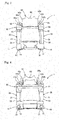
assistant robot 1 of a first embodiment will be described with reference toFigs. 1 to 5 . Theassistant robot 1 supports a part (for example, the upper body) of the body of a person in need of assistance M1 (illustrated inFigs. 13 and14 ) and assists standing actions and seating actions. As illustrated inFigs. 1 to 5 , theassistant robot 1 includes abase 10, lifting and loweringarms sections 40, aholding section 50, lifting and loweringactuators backward movement actuators control device 120. In the following description, each of front, back, left, and right is set to be front, back, left, and right when the travelling direction of theassistant robot 1 is considered as forward. - The
base 10 is a portion that is placed on the ground. As illustrated inFig. 2 , thebase 10 is formed in a U shape so as to be open backwards when seen in a plan. Thebase 10 includes fourwheels 15 to 18 and is capable of moving forwards and backwards. - The lifting and lowering
arms base 10 and are provided so as to be capable of stretching upwards. As illustrated inFigs. 1 and5 , the lifting and loweringarms sections 40 are provided on the upper ends of the lifting and loweringarms arms sections 40 lift and lower with respect to thebase 10. That is, as illustrated inFigs. 1 and5 , the lifting and loweringsections 40 linearly move forwards as the lifting and lowering sections lift with respect to thebase 10. - The
holding section 50 is located on the upper sides of the lifting and loweringsections 40 and is supported by the lifting and loweringsections 40. Theholding section 50 moves in a forward, backward, and inclined manner with respect to the lifting and loweringsections 40. The holdingsection 50 holds a part of the body of the person in need of assistance M1. The holdingsection 50 includes anattachment 60 that can be exchanged with other attachments depending on the person in need of assistance M1. - The lifting and lowering
actuators sections 40 to lift and lower with respect to thebase 10. The lifting and loweringactuators arms sections 40 are driven using the lifting and loweringactuators Fig. 5 from a state illustrated inFig. 1 and vice versa. The lifting and loweringactuators base 10 and the lifting and loweringarms - The forward-and-
backward movement actuators section 50 to move in a forward, backward, and inclined manner with respect to the lifting and loweringsections 40. That is, the holdingsection 50 is driven using the forward-and-backward movement actuators sections 40 to the location illustrated inFig. 5 from the state illustrated inFig. 1 and vice versa. The forward-and-backward movement actuators sections 40 and the holdingsection 50. Thecontrol device 120 controls the lifting and loweringactuators backward movement actuators - As illustrated in
Figs. 1 to 5 , theassistant robot 1 includes acover 11 for thebase 10, covers 25 and 35 for the lifting and loweringarms sections 40, and theattachment 60 in the holdingsection 50. Therefore, the internal constitution of theassistant robot 1 obtained by removing these covers and attachment will be described with reference toFigs. 6 to 8 . However, the lifting and loweringsections 40, the holdingsection 50, and the forward-and-backward movement actuators - The
base 10 includes right and leftframes coupling frame 14 that couples the front end portions of the right and leftframes frames back wheels frames front wheels frames front wheels assistant robot 1. Here, in the present embodiment, the right and leftback wheels front wheels back wheels front wheels - The lifting and lowering
arms first arm sections second arm sections third arm sections first arm sections second arm sections third arm sections first arm sections frames base 10. Thefirst arm sections - The
second arm sections first arm sections second arm sections second arm sections first arm sections third arm sections second arm sections sections 40 are fixed to the upper ends of thethird arm sections third arm sections third arm sections second arm sections - Therefore, when the
second arm sections third arm sections third arm sections first arm sections second arm sections Fig. 1 . At this time, the lifting and loweringsections 40 are located at the lowermost location. Meanwhile, when thesecond arm sections third arm sections third arm sections first arm sections first arm sections Figs. 5 to 8 . At this time, the lifting and loweringsections 40 are located at the uppermost location. - The lifting and lowering
actuators rotary driving sources mechanisms mechanisms rotary driving sources rotary driving sources - The first lifting and lowering
mechanisms rotary driving sources second arm sections first arm sections mechanisms mechanisms mechanisms screw shafts rotary driving sources nut members screw shafts first arm sections nut members second arm sections screw shafts rotary driving sources nut members second arm sections first arm sections - The second lifting and lowering
mechanisms third arm sections second arm sections mechanisms mechanisms mechanisms lower pulleys upper pulleys second arm sections - Furthermore, the second lifting and lowering
mechanisms belts lower pulleys upper pulleys belts end coupling members first arm sections end coupling members 23a and 33a of thethird arm sections second arm sections first arm sections belts third arm sections second arm sections second arm sections third arm sections - The lifting and lowering
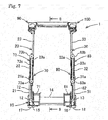
sections 40, the holdingsection 50, and the forward-and-backward movement actuators Figs. 9 to 11 . Here, in the following description, a coupled structure between the left side portion of the lifting and loweringsection 40 and the left side portion of the holdingsection 50 will be described. Therefore, the right-side forward-and-backward movement actuator 100 will not be described. Although not described, the coupled structure between the right side portion of the lifting and loweringsection 40 and the right side portion of the holdingsection 50 is a bilaterally symmetric structure of the left-side structure. - The lifting and lowering
sections 40 are fixed to the upper ends of thethird arm sections 23. In addition, the holdingsection 50 moves in a forward, backward, and inclined manner with respect to the lifting and loweringsections 40. Here, in theassistant robot 1 of the present embodiment, the holdingsection 50 includesguide paths 53 which are rail members, the lifting and loweringsections 40 include guidedmembers 43,screw shafts 93 of the forward-and-backward movement actuators section 50, andnut members 94 are provided in the lifting and loweringsections 40. - As illustrated in
Figs. 9 and10 , the lifting and loweringsections 40 includebase sections 41,oscillation support sections 42, and the guidedmembers 43. As illustrated inFig. 10 , thebase sections 41 are formed in a crank shape when seen in the forward-and-backward direction and are fixed to the upper ends of thethird arm sections Fig. 10 , theoscillation support section 42 in the lifting and loweringsection 40 is formed in a U shape so as to be open downwards when seen in the forward-and-backward direction and is fixed to one side surface (the right side ofFig. 10 ) of thebase section 41. In addition, the guidedmember 43 is a member that is held in theguide path 53 described below so as to be capable of moving. The guidedmember 43 has a groove on one side surface and is formed in a block shape. The guidedmember 43 is fixed to the other side surface (the left side inFig. 10 ) of thebase section 41. That is, thebase section 41, theoscillation support section 42, and the guidedmember 43 which constitute the lifting and loweringsection 40 are integrally formed. - The holding
section 50 includes amain body frame 51,oscillation support sections 52, and theguide paths 53. Themain body frame 51 is formed in a U shape so as to be open backwards when seen from above.Fig. 9 illustrates an extended portion of the left side of themain body frame 51, andFig. 10 illustrates a part of the extended portion and the central coupled portion of themain body frame 51. As illustrated inFig. 10 , theoscillation support section 52 in the holdingsection 50 is formed in a U shape so as to be open downwards when seen in the forward-and-backward direction. Theoscillation support section 52 in the holdingsection 50 is located at a location at which the oscillation support section overlaps theoscillation support sections 42 in the lifting and loweringsections 40 in the forward-and-backward direction and is located ahead of theoscillation support section 42 in the lifting and loweringsection 40. - The
guide paths 53 are rail members and are fixed to side surfaces of the right and left extended portions of themain body frame 51. Theguide path 53 is formed so as to extend in the forward-and-backward direction. In the present embodiment, theguide path 53 is formed in a curved non-linear shape, particularly, an arc shape. Theguide path 53 is fixed to themain body frame 51 so as to have the front end at the lowest location and have an upward arc shape as illustrated inFig. 9 . Theguide path 53 is fitted into the guidedmember 43 in the vertical direction and holds the guidedmember 43. That is, theguide path 53 moves the guidedmember 43 in an arc shape along theguide path 53 as illustrated inFigs. 9 and11 . - When the guided
members 43 move in an arc shape along theguide paths 53, themain body frame 51 in the holdingsection 50 moves in a forward, backward, and inclined manner with respect to the lifting and loweringsections 40 as illustrated inFigs. 9 and11 . In detail, when a state in which the guidedmembers 43 are located at the front ends of theguide paths 53 as illustrated inFig. 9 transfers to a state in which the guidedmembers 43 are located at the back ends of theguide paths 53 as illustrated inFig. 11 , themain body frame 51 in the holdingsection 50 moves forwards and is inclined at the front. In addition, in a case in which a state in which the locational relationship between the guidedmembers 43 and theguide paths 53 is as illustrated inFig. 11 transfers to a state illustrated inFig. 9 , themain body frame 51 in the holdingsection 50 moves backwards and falls into a horizontal state. As described above, theguide paths 53 guide the holdingsection 50 to move in a forward, backward, and inclined manner with respect to the lifting and loweringsections 40 through the guidedmembers 43. - The forward-and-
backward movement actuators section 50 to move in a forward, backward, and inclined manner with respect to the lifting and loweringsections 40 as described above. Here, the number of the forward-and-backward movement actuators is two (the left-side forward-and-backward movement actuator 90 and the right-side forward-and-backward movement actuator 100), but the forward-and-backward movement actuators perform one kind of driving action to drive the holdingsection 50 with respect to the right and left lifting and loweringsections 40. That is, the two forward-and-backward movement actuators backward movement actuators section 50 to move in a forward, backward, and inclined manner with respect to the lifting and loweringsections 40 with one kind of driving action. - As illustrated in
Figs. 9 and10 , the forward-and-backward movement actuator 90 includes the supportedmember 91, therotary driving source 92, thescrew shaft 93, and thenut member 94. The supportedmember 91 has a through-hole formed in the center and is formed in a block shape. The supportedmember 91 is supported by a U-shaped opening end of theoscillation support section 52 in the holdingsection 50 so as to be capable of oscillating using the horizontal direction as a rotation axis line. - The
rotary driving source 92 is, for example, a motor. Therotary driving source 92 is fixed to the supportedmember 91. That is, therotary driving source 92 becomes capable of moving in an inclined manner with respect to theoscillation support section 52 in the holdingsection 50. Thescrew shaft 93 is coupled to the output axis of therotary driving source 92 and is rotary-driven using therotary driving source 92. Thescrew shaft 93 is supported by the supportedmember 91 so as to be capable of rotating around an axis line of thescrew shaft 93. That is, thescrew shaft 93 becomes capable of moving in an inclined manner with respect to theoscillation support section 52 together with therotary driving source 92. Thenut member 94 is supported by a U-shaped opening end of theoscillation support section 42 in the lifting and loweringsection 40 so as to be capable of moving in an inclined manner using the horizontal direction as a rotation axis line. Thenut member 94 is engaged with thescrew shaft 93 and moves along thescrew shaft 93 in accordance with the rotation of thescrew shaft 93. - That is, the
rotary driving source 92 rotates thescrew shaft 93 by means of rotary drive and, furthermore, moves thenut member 94 in the forward-and-backward direction in accordance with the rotation of thescrew shaft 93. In accordance with the rotation of therotary driving source 92, the distance between the supportedmember 91 that supports one end of thescrew shaft 93 and thenut member 94 changes. At this time, as described above, the posture of the holdingsection 50 with respect to the lifting and loweringsections 40 is determined by the movement of the guidedmembers 43 in an arc shape along theguide paths 53. Therefore, thescrew shaft 93 and thenut member 94 move in an inclined manner due to the movement of the holdingsection 50 with respect to the lifting and loweringsections 40 in a forward, backward, and inclined manner. - The
attachment 60 will be described with reference toFigs. 1 to 4 . Theattachment 60 includes amain body section 61, atrunk pad 62, right and leftgrips elbow rest sections armpit holding sections operation section 66. Themain body section 61 is mounted so as to be attachable to or detachable from themain body frame 51 in the holding section 50 (illustrated inFig. 9 ). - The
trunk pad 62 is formed of a cushion material in an almost plate shape. Thetrunk pad 62 is located in the central portion in the horizontal direction and in the central portion in the forward-and-backward direction of theentire attachment 60 on the upper surface of themain body section 61. Thetrunk pad 62 is provided so that the upper surface thereof is slightly inclined backwards. Thetrunk pad 62 supports almost all of the trunk of the person in need of assistance M1, that is, chest to abdomen and the vicinity of the left armpit to the vicinity of the right armpit. Particularly, thetrunk pad 62 is formed to have a narrower horizontal width in the upper half which corresponds to chest than that in the lower half which corresponds to abdomen. Therefore, the person in need of assistance M1 is able to locate both armpits without any discomfort and obtain a feeling of the vicinity of abdomen stably supported. Furthermore, the upper edge of thetrunk pad 62 is formed in a concave shape so as to allow the head of the person in need of assistance M1 to move without any hindrance. The lower edge of thetrunk pad 62 is formed in a concave shape so as to allow the leg section to enter the trunk pad and allow the waist portion to be stably supported. - The
grips main body section 61. Theelbow rest sections main body section 61. Theoperation section 66 includes buttons that the person in need of assistance M1 or a caregiver operates. Thearmpit holding sections trunk pad 62. Thearmpit holding sections operation section 66 includes buttons for lifting and lowering operation. When the person in need of assistance M1 operates the buttons for lifting and lowering operation in theoperation section 66, the lifting and loweringsections 40 perform lifting and lowering movement, and the holdingsection 50 moves in a forward, backward, and inclined manner in synchronization with the lifting and lowering movement of the lifting and loweringsections 40. - Meanwhile, in the
attachment 60, each of thetrunk pad 62, the right and leftgrips elbow rest sections armpit holding sections operation section 66 can be individually exchanged with new members. In addition, theattachment 60 does not need to include all of thetrunk pad 62, the right and leftgrips elbow rest sections armpit holding sections operation section 66 and may have a constitution including only appropriately-selected members. - The constitution of the
control device 120 will be described with reference toFig. 12 . Simultaneously, the actions of theassistant robot 1 will be described with reference toFigs. 13 and14 . Thecontrol device 120 includes a calculatingsection 121 such as CPU and amemory section 122 such as HDD or Flash SSD. Although not illustrated, thecontrol device 120 includes an interface for communication with theoperation section 66, the lifting and loweringactuators backward movement actuators - The calculating
section 121 acquires operation information from theoperation section 66 in a case in which the person in need of assistance M1 operates theoperation section 66. The operation information is about lifting actions, lowering actions, and stoppage actions with respect to the holdingsection 50. Furthermore, the calculatingsection 121 acquires the current state information of each of theactuators section 121 synchronously controls the lifting and loweringactuators backward movement actuators respective actuators memory section 122. Here, thememory section 122 memorizes the operation information, the current states of therespective actuators respective actuators - When the person in need of assistance M1 is in a sitting posture, immediately after the person in need of assistance M1 is held in the
trunk pad 62 in theattachment 60 in the holdingsection 50, the calculatingsection 121 first drives the forward-and-backward movement actuators section 50 in a forward, backward, and inclined manner as illustrated inFig. 13 . After that, the calculatingsection 121 drives the lifting and loweringactuators backward movement actuators section 50 lifts while moving in a forward, backward, and inclined manner as illustrated inFig. 14 . The lift height of the holdingsection 50 can be set in accordance with the height of the person in need of assistance M1. In addition, even in a case in which the person in need of assistance M1 transfers from a stand-up posture to a sitting posture, similarly, lifting and lowering movement using the lifting and loweringactuators backward movement actuators - Lifting and lowering
sections 240, a holdingsection 250, and forward-and-backward movement actuators 260 in anassistant robot 200 of a second embodiment will be described with reference toFigs. 15 and 16. Figs. 15 and 16 illustrate, similar toFigs. 9 and10 in the first embodiment, a coupled structure between the left side portion of the lifting and loweringsection 240 and the left side portion of the holdingsection 250. - Here, in the
assistant robot 200 of the present embodiment, the holdingsection 250 includesguide paths 253 which are rail members, the lifting and loweringsections 240 include guidedmembers 243,screw shafts 262 of the forward-and-backward movement actuators 260 are provided in the lifting and loweringsections 240, andnut members 263 are provided in theholding section 250. - The lifting and lowering
sections 240 are mounted on the upper ends of thethird arm sections 23. The lifting and loweringsection 240 includes abase section 241, a both-end support section 242, and a guidedmember 243. Thebase section 241 is constituted in the same manner as thebase section 41 in the first embodiment. The both-end support section 242 has flange portions at both ends of a long portion. The central portion of the both-end support section 242 is supported by one side surface (the near surface inFig. 15 ) of thebase section 241 so that the both-end support section is capable of moving in an inclined manner around an axial line of theassistant robot 1 in the horizontal direction. The guidedmember 243 is fixed to the other side surface (the far surface inFig. 15 ) of thebase section 241. - The holding
section 250 includes amain body frame 251,oscillation support sections 252, and guidepaths 253. Theoscillation support section 252 is formed in themain body frame 251 in a U shape so as to be open downwards in a case in which the oscillation support section is seen in the forward-and-backward direction. Theguide paths 253 are rail members and are fixed to side surfaces of the right and left extended portions of themain body frame 251. Theguide path 253 is formed so as to extend in the forward-and-backward direction. Theguide path 253 is formed in a curved non-linear shape, particularly, an arc shape. Theguide path 253 is fitted into the guidedmember 243 in the vertical direction and holds the guidedmember 243. That is, theguide path 253 moves the guidedmember 243 in an arc shape along theguide path 253 as illustrated inFigs. 15 and 16 . - The forward-and-
backward movement actuator 260 includes arotary driving source 261, ascrew shaft 262, and anut member 263 as illustrated inFigs. 15 and 16 . Therotary driving source 261 is fixed to one flange portion of the both-end support section 242 in the lifting and loweringsection 240. That is, therotary driving source 261 becomes capable of moving in an inclined manner with respect to thebase section 241 in the lifting and loweringsection 240. Thescrew shaft 262 is coupled to the output axis of therotary driving source 261 and is rotary-driven using therotary driving source 261. Thescrew shaft 262 has both ends that are supported by the both flange portions of the both-end support section 242 in the lifting and loweringsection 240 so that the screw shaft is capable of rotating around the axis line of thescrew shaft 262. That is, thescrew shaft 262 becomes capable of moving in an inclined manner with respect to thebase section 241 in the lifting and loweringsection 240 together with therotary driving source 261. Thenut member 263 is supported by a U-shaped opening end of theoscillation support section 252 in theholding section 250 so as to be capable of moving in an inclined manner using the horizontal direction as a rotation axis line. Thenut member 263 is engaged with thescrew shaft 262 and moves along thescrew shaft 262 in accordance with the rotation of thescrew shaft 262. - The holding
section 250 acts with respect to the lifting and loweringsections 240 in the same manner as in the first embodiment. That is, in a state illustrated inFig. 15 as the initial state, therotary driving sources 261 rotary-drive thescrew shafts 262 to rotate, and thenut members 263 move in a unidirectional manner along thescrew shafts 262 in accordance with the rotation of thescrew shafts 262. In such a case, the both-end support sections 242 in the lifting and loweringsections 240 which support thescrew shafts 262 and theoscillation support sections 252 in theholding section 250 which support thenut members 263 come close to each other. - At this time, the guided
members 243 move in an arc shape along theguide paths 253. Therefore, the holdingsection 250 moves forwards and is inclined at the front with respect to the lifting and loweringsections 240 as illustrated inFig. 16 . On the other hand, in a case in which therotary driving sources 261 rotary-drive the screw shafts in the reverse direction, the holdingsection 250 acts with respect to the lifting and loweringsections 240 in a reverse manner. - Lifting and lowering
sections 340, a holdingsection 350, and forward-and-backward movement actuators 360 in anassistant robot 300 of a third embodiment will be described with reference toFigs. 17 and 18. Figs. 17 and 18 illustrate, similar toFigs. 9 and10 in the first embodiment, a coupled structure between the left side portion of the lifting and loweringsection 340 and the left side portion of the holdingsection 350. - Here, in the
assistant robot 300 of the present embodiment, the lifting and loweringsections 340 includeguide paths section 350 includes guidedmembers screw shafts 262 of the forward-and-backward movement actuators 360 are provided in the lifting and loweringsections 340, andnut members 363 are provided in theholding section 250. - The lifting and lowering
sections 340 are mounted on the upper ends of thethird arm sections 23. The lifting and loweringsection 340 includes abase section 341, afirst guide path 342, and asecond guide path 343. Unlike thebase section 41 in the first embodiment, thebase section 341 is formed to be long in the forward-and-backward direction enough to fix theguide paths first guide path 342 is formed to be linear and is horizontally disposed in the back part of a side surface of thebase section 341 so as to extend in the forward-and-backward direction. Thesecond guide path 343 is formed to be linear and is disposed in the front part of the side surface of thebase section 341 an angle inclined with respect to the horizontal surface so as to extend in the forward-and-backward direction. In detail, thesecond guide path 343 is provided so that the front end is located below the back end. - The holding
section 350 includes amain body frame 351, a first guidedmember 352, and a second guidedmember 353 . The first guidedmember 352 is supported by the back part of themain body frame 351 so as to be capable of moving in an inclined manner using the horizontal direction of theassistant robot 300 as a rotation axis line. The first guidedmember 352 is held in thefirst guide path 342 so as to pinch thefirst guide path 342 in the lifting and loweringsection 340 in the vertical direction. The first guidedmember 352 moves linearly (in the forward-and-backward direction and horizontally) along thefirst guide path 342. - The second guided
member 353 is supported by the front part of themain body frame 351 so as to be capable of moving in an inclined manner using the horizontal direction as a rotation axis line. The second guidedmember 353 is held in thesecond guide path 343 so as to pinch thesecond guide path 343 in the lifting and loweringsection 340 in the vertical direction. The second guidedmember 353 moves linearly (in the forward-and-backward direction so as to be inclined at the front) along thesecond guide path 343. - The forward-and-
backward movement actuator 360 includes arotary driving source 361, ascrew shaft 362, and anut member 363. Therotary driving source 361 is fixed to thebase section 341 in the lifting and loweringsection 340. Thescrew shaft 362 is coupled to the output axis of therotary driving source 361 and is rotary-driven using therotary driving source 361. That is, therotary driving source 361 and thescrew shaft 362 are supported so as to be incapable of moving in an inclined manner with respect to the lifting and loweringsection 340. Here, the axis line of thescrew shaft 362 is horizontally disposed so as to extend in the forward-and-backward direction. - The
nut member 363 is engaged with thescrew shaft 362 and moves along thescrew shaft 362 in accordance with the rotation of thescrew shaft 362. Thenut member 363 is fixed to the first guidedmember 352 in theholding section 350. That is, the first guidedmember 352 in theholding section 350 moves in accordance with the movement of thenut member 363. - The holding
section 350 acts with respect to the lifting and loweringsections 340 in the same manner as in the first embodiment. That is, in a state illustrated inFig. 17 as the initial state, therotary driving sources 361 rotary-drive thescrew shafts 362 to rotate, and thenut members 363 move forwards along thescrew shafts 362 in accordance with the rotation of thescrew shafts 362. - At this time, the first guided
members 352 move linearly and horizontally along thefirst guide paths 342. On the other hand, the second guidedmembers 353 move linearly along thesecond guide paths 343 so as to be inclined at the front. Therefore, the holdingsection 350 moves forwards and is inclined at the front with respect to the lifting and loweringsections 340 as illustrated inFig. 18 . On the other hand, in a case in which therotary driving sources 361 rotary-drive the screw shafts in the reverse direction, the holdingsection 350 acts with respect to the lifting and loweringsections 340 in a reverse manner. - Lifting and lowering
sections 440, a holdingsection 450, and forward-and-backward movement actuators 460 in anassistant robot 400 of a fourth embodiment will be described with reference toFigs. 19 and 20. Figs. 19 and 20 illustrate, similar toFigs. 9 and10 in the first embodiment, a coupled structure between the left side portion of the lifting and loweringsection 440 and the left side portion of the holdingsection 450. - Here, in the
assistant robot 400 of the present embodiment, the holdingsection 450 includesguide paths 451a which are grooves, the lifting and loweringsections 440 include guidedmembers main body sections 461 of the forward-and-backward movement actuators 460 are provided in the lifting and loweringsections 440, androd sections 462 of the forward-and-backward movement actuators 460 are provided in theholding section 450. - The lifting and lowering
sections 440 are mounted on the upper ends of thethird arm sections 23. The lifting and loweringsection 440 includes abase section 441, anoscillation support section 442, a first guidedmember 443, and a second guidedmember 444. Theoscillation support section 442 is provided in the front part of a side surface of thebase section 441. The first guidedmember 443 and the second guidedmember 444 are protruding members that are provided in the back parts of the side surfaces of thebase section 441 so as to protrude toward the side parts. The first guidedmember 443 and the second guidedmember 444 are provided so as to be arranged almost in the forward-and-backward direction. - The holding
section 450 includes amain body frame 451 andoscillation support sections 452. Theguide paths 451a which are grooves that are open toward the side parts are formed on the side surfaces of themain body frame 451. Theguide path 451a is formed in a non-linear shape extending in the forward-and-backward direction. The front part of theguide path 451a is formed in a linear shape extending in the forward-and-backward direction, and the back part of theguide path 451a is formed in a continuously curved shape in the linear portion. The back end of theguide path 451a is located below the front end. That is, theguide path 451a forms a cam groove. The first guidedmember 443 and the second guidedmember 444 are inserted into theguide path 451a so as to be capable of moving along theguide path 451a. When the first guidedmember 443 and the second guidedmember 444 are inserted into theguide path 451a, the posture of the holdingsection 450 is stabilized with respect to the lifting and loweringsection 440. Theoscillation support section 452 is provided at the back end of themain body frame 451. - The forward-and-
backward movement actuator 460 is a cylinder mechanism. The forward-and-backward movement actuator 460 includes amain body section 461 and arod section 462. Themain body section 461 is supported by theoscillation support section 442 in the lifting and loweringsection 440 so as to be capable of moving in an inclined manner using the horizontal direction of theassistant robot 400 as a rotation axis line. Therod section 462 acts so that the protruding amount changes with respect to themain body section 461. The front end of therod section 462 is supported by theoscillation support section 452 in theholding section 450 so as to be capable of moving in an inclined manner using the horizontal direction of theassistant robot 400 as a rotation axis line. - In the present embodiment, the holding
section 450 acts with respect to the lifting and loweringsections 440 in the same manner as in the first embodiment. That is, in a state illustrated inFig. 19 as the initial state, therod section 462 transfers from a state of being extended with respect to themain body section 461 to a state of being contracted with respect to the main body section, theoscillation support section 452 in theholding section 450 comes close to theoscillation support section 442 in the lifting and loweringsection 440. At this time, the first guidedmember 443 and the second guidedmember 444 relatively move along theguide path 451a which is a groove. In such a case, as illustrated inFig. 20 , the holdingsection 450 is inclined forwards while moving forwards with respect to the lifting and loweringsection 440. On the other hand, when the forward-and-backward movement actuators 460 are caused to act in a reverse manner, the holdingsection 450 acts with respect to the lifting and loweringsections 440 in a reverse manner. - Meanwhile, in the fourth embodiment, the
guide path 451a is formed in theholding section 450, and the guidedmembers section 440, but theguide path 451a may be formed in the lifting and loweringsection 440, and the guidedmembers holding section 450. - The
assistant robots base 10, the lifting and loweringsections base 10, the holdingsections sections actuators sections base 10, and the forward-and-backward movement actuators sections sections - One of the lifting and lowering
sections sections guide paths sections sections sections sections members guide paths - The holding
sections sections backward movement actuators sections sections backward movement actuators backward movement actuators sections sections sections base 10, the forward-and-backward movement actuators - Furthermore, the forward-and-
backward movement actuators sections assistant robots sections assistant robots - In addition, in the
assistant robots guide paths members guide paths sections sections guide paths members backward movement actuators - In the
assistant robot 400 of the fourth embodiment, theguide path 451a is a groove which is formed in one of the lifting and loweringsection 440 and theholding section 450, and the guidedmembers guide path 451a so as to be capable of relatively moving in theguide path 451a. In this case, theguide path 451a is not an exclusive member and is formed in one of the lifting and loweringsection 440 and theholding section 450, and thus the number of components decreases. Furthermore, since the degree of freedom in designing the shape of the groove is high, the degree of freedom of the holdingsection 450 acting with respect to the lifting and loweringsection 440 is high. - In the
assistant robots sections guide paths sections members guide paths guide paths members guide paths - In addition, the holding
sections sections guide paths sections assistant robots - In the
assistant robot 1 of the first embodiment, the forward-and-backward movement actuators rotary driving sources 92 which are provided in the holdingsection 50, thescrew shafts 93 which are coupled to the output axes of therotary driving sources 92 and are rotary-driven using therotary driving sources 92, and thenut members 94 which are provided in the lifting and loweringsections 40, are engaged with thescrew shafts 93, and move to thescrew shafts 93 in accordance with the rotation of thescrew shafts 93. In this case, thescrew shafts 93 in the forward-and-backward movement actuators section 50. Thescrew shafts 93 have lengths. The holdingsection 50 holds a part of the body of the person in need of assistance M1 and thus has a length to a certain extent. Therefore, when thescrew shafts 93 are held in the holdingsection 50 having an original length, it is possible to shorten the lengths in the forward-and-backward direction of members which are provided in the lifting and loweringsections 40. As a result, the full length of theassistant robot 1 in the forward-and-backward direction becomes short. - Furthermore, in the
assistant robot 1 of the first embodiment, therotary driving sources 92 and thescrew shafts 93 are supported by the holdingsection 50 so as to be capable of moving in an inclined manner, and thenut members 94 are supported by the lifting and loweringsections 40 so as to be capable of moving in an inclined manner. In this case, in a case in which the holdingsection 50 moves in a forward, backward, and inclined manner with respect to the lifting and loweringsections 40, thescrew shafts 93 move in an inclined manner in accordance with the inclination angle of the holdingsection 50. Therefore, the sizes of the forward-and-backward movement actuators - In the
assistant robots backward movement actuators rotary driving sources sections screw shafts rotary driving sources rotary driving sources nut members 63 and 363 which are provided in the holdingsections screw shafts screw shafts screw shafts rotary driving sources sections rotary driving sources - In addition, in the
assistant robot 200 of the second embodiment, therotary driving sources 261 and thescrew shafts 262 are supported by the lifting and loweringsections 240 so as to be capable of moving in an inclined manner, and thenut members 263 are supported by the holdingsections 250 so as to be capable of moving in an inclined manner. In this case, in a case in which theholding section 250 moves in a forward, backward, and inclined manner with respect to the lifting and loweringsections 240, thescrew shafts 262 move in an inclined manner in accordance with the inclination angle of the holdingsection 250. Therefore, the sizes of the forward-and-backward movement actuators 260 in the vertical direction are reduced. - In addition, in the
assistant robot 300 of the third embodiment, therotary driving sources 361 and thescrew shafts 362 are supported by the lifting and loweringsections 340 so as to be incapable of moving in an inclined manner, and thenut members 363 are supported by the holdingsections 350 so as to be capable of moving in an inclined manner. Therotary driving sources 361 and thescrew shafts 362 move in accordance with the lifting and lowering action of the lifting and loweringsection 340, but do not follow the forward, backward, and inclined movement of the holdingsection 350. Therefore, there is a little opportunity that therotary driving sources 361 and thescrew shafts 362 are imparted with vibrations from the outside. Therefore, the service lives of therotary driving sources 361 and thescrew shafts 362 extend. - In addition, in the
assistant robot 200 of the second embodiment, both ends of thescrew shafts 262 are supported by the lifting and loweringsections 240. Since thescrew shafts 262 are stably held, even in a case in which theassistant robot 200 acts, the engagement state between thescrew shafts 262 and thenut members 263 is favorably maintained. Therefore, the service lives of thescrew shafts 262 and thenut members 263 extend. - In addition, in the
assistant robots sections base 10. Here, in a case in which the person in need of assistance M1 transfers from a seating posture to a standing posture, the holdingsections sections sections sections sections sections guide paths assistant robots - In the
assistant robots guide paths guide paths sections sections assistant robot 300 of the third embodiment, theguide path 343 is linearly formed in an inclined manner. The formation of theguide path 343 becomes easy. - In addition, in the
assistant robots backward movement actuators sections sections - That is, in the
assistant robots sections assistant robots sections sections assistant robots assistant robots - 1, 200, 300, 400: assistant robot, 10: base, 20, 30: lifting and lowering arm, 23, 33: third arm section, 40, 240, 340, 440: lifting and lowering section, 41, 241, 341, 441: base section, 43, 243, 352, 353, 443, 444: guided member, 50, 250, 350, and 450: holding section, 51, 251, 351, 451: main body frame, 53, 253, 342, 343, 451a: guide path, 60: attachment, 70, 80: lifting and lowering actuator, 90, 100, 260, 360, 460: forward-and-backward movement actuator, 92, 261, 361: rotary driving source, 93, 262, 362: screw shaft, 94, 263, 363: nut member, 120: control device, M1: person in need of assistance
Claims (11)
- An assistant robot comprising:a base (10);a lifting and lowering section (40) which is configured to lift and lower with respect to the base (10); anda lifting and lowering actuator (70, 80) which is configured to drive the lifting and lowering section (40) to lift and lower with respect to the base (10); anda holding section (50) which is configured to hold a part of a body of a person in need of assistance and to move in a forward, backward, and inclined manner with respect to the lifting and lowering section (40);a forward-and-backward movement actuator (90, 100) which is configured to drive the holding section (50) to move in a forward, backward, and inclined manner with respect to the lifting and lowering section (40),characterised in thatone of the lifting and lowering section (40) and the holding section (50) includes a guide path (53) which is formed in a curved non-linear shape and is formed to extend in a forward-and-backward direction and is configured to guide the holding section (50) to move in a forward, backward, and inclined manner with respect to the lifting and lowering section (40), andthe other of the lifting and lowering section (40) and the holding section (50) includes a guided member (43) which is configured to move along the guide path (53).
- The assistant robot according to Claim 1,
wherein the guide path (53) is a rail member, and
the guided member (43) is a member which is held in the guide path (53) so as to be capable of relatively moving. - The assistant robot according to Claim 1,
wherein the guide path (53) is a groove which is formed in one of the lifting and lowering section (40) and the holding section (50), and
the guided member (43) is a protruding member which is inserted into the guide path (53) so as to be capable of relatively moving in the guide path (53). - The assistant robot according to any one of Claims 1 to 3,
wherein the holding section (50) includes the guide path (53), and
the lifting and lowering section (40) includes the guided member (43). - The assistant robot according to any one of Claims 1 to 4,
wherein the forward-and-backward movement actuator (90, 100) includes a rotary driving source (92) which is provided in the holding section (50),
a screw shaft (93) which is coupled to an output axis of the rotary driving source (92) and is rotary-driven by the rotary driving source (92), and
a nut member (94) which is provided in the lifting and lowering section (40), is engaged with the screw shaft (93), and is configured to move along the screw shaft (93) in accordance with rotation of the screw shaft (93). - The assistant robot according to Claim 5,
wherein the rotary driving source (92) and the screw shaft (93) are supported by the holding section (50) so as to be capable of moving in an inclined manner, and
the nut member (94) is supported by the lifting and lowering section (40) so as to be capable of moving in an inclined manner. - The assistant robot according to any one of Claims 1 to 4,
wherein the forward-and-backward movement actuator (90, 100) includes a rotary driving source (92) which is provided in the lifting and lowering section (40),
a screw shaft (93) which is coupled to an output axis of the rotary driving source (92) and is rotary-driven by the rotary driving source (92), and
a nut member (94) which is provided in the holding section (50), is engaged with the screw shaft (93), and is configured to move along the screw shaft (93) in accordance with rotation of the screw shaft (93). - The assistant robot according to Claim 7,
wherein the rotary driving source (92) and the screw shaft (93) are supported by the lifting and lowering section (40) so as to be capable of moving in an inclined manner, and
the nut member (94) is supported by the holding section (50) so as to be capable of moving in an inclined manner. - The assistant robot according to Claim 7,
wherein the rotary driving source (92) and the screw shaft (93) are supported by the lifting and lowering section (40) so as to be incapable of moving in an inclined manner, and
the nut member (94) is supported by the holding section (50) so as to be capable of moving in an inclined manner. - The assistant robot according to any one of Claims 7 to 9,
wherein both ends of the screw shaft (93) are supported by the lifting and lowering section (40). - The assistant robot according to any one of Claims 1 to 10,
wherein the lifting and lowering section (40) is configured to linearly move forwards as the lifting and lowering section (40) lifts with respect to the base (10).
Applications Claiming Priority (2)
| Application Number | Priority Date | Filing Date | Title |
|---|---|---|---|
| PCT/JP2014/059268 WO2015145758A1 (en) | 2014-03-28 | 2014-03-28 | Assistance robot |
| PCT/JP2014/084660 WO2015145915A1 (en) | 2014-03-28 | 2014-12-26 | Assistance robot |
Publications (4)
| Publication Number | Publication Date |
|---|---|
| EP3124002A1 EP3124002A1 (en) | 2017-02-01 |
| EP3124002A4 EP3124002A4 (en) | 2017-03-15 |
| EP3124002B1 true EP3124002B1 (en) | 2018-09-26 |
| EP3124002B8 EP3124002B8 (en) | 2018-11-28 |
Family
ID=54194344
Family Applications (2)
| Application Number | Title | Priority Date | Filing Date |
|---|---|---|---|
| EP14887416.7A Pending EP3123995A4 (en) | 2014-03-28 | 2014-03-28 | Assistance robot |
| EP14887502.4A Active EP3124002B8 (en) | 2014-03-28 | 2014-12-26 | Assistance robot |
Family Applications Before (1)
| Application Number | Title | Priority Date | Filing Date |
|---|---|---|---|
| EP14887416.7A Pending EP3123995A4 (en) | 2014-03-28 | 2014-03-28 | Assistance robot |
Country Status (4)
| Country | Link |
|---|---|
| EP (2) | EP3123995A4 (en) |
| JP (2) | JP6310060B2 (en) |
| CN (1) | CN106163479B (en) |
| WO (2) | WO2015145758A1 (en) |
Families Citing this family (12)
| Publication number | Priority date | Publication date | Assignee | Title |
|---|---|---|---|---|
| US10045896B2 (en) * | 2014-12-04 | 2018-08-14 | Tsushima Ironworks Co., Ltd. | Standing-up assist tool and walking support device |
| JP7007912B2 (en) | 2015-10-06 | 2022-01-25 | 株式会社Fuji | Caregiving device |
| AU2016336284B2 (en) * | 2015-10-06 | 2019-09-19 | Fuji Corporation | Assistance device |
| SG11201802315SA (en) * | 2015-10-06 | 2018-04-27 | Fuji Machine Mfg Co Ltd | Assisting robot |
| JP6586472B2 (en) * | 2016-01-14 | 2019-10-02 | 株式会社Fuji | Assistance device, assistance facility, and assistance method |
| CN109069333B (en) * | 2016-05-17 | 2020-07-17 | 株式会社富士 | Mediation device |
| EP3513775A4 (en) * | 2016-09-13 | 2019-09-18 | Fuji Corporation | Assistance device |
| JP6709296B2 (en) * | 2016-12-22 | 2020-06-10 | 株式会社Fuji | Assistance device |
| JP7108448B2 (en) * | 2018-04-06 | 2022-07-28 | 株式会社Fuji | assistive device |
| WO2020021619A1 (en) * | 2018-07-24 | 2020-01-30 | 株式会社Fuji | Assistive device suitability determination device |
| WO2020208832A1 (en) * | 2019-04-12 | 2020-10-15 | 株式会社Fuji | Caring device |
| WO2021048965A1 (en) * | 2019-09-12 | 2021-03-18 | 株式会社Fuji | Assistance device |
Family Cites Families (26)
| Publication number | Priority date | Publication date | Assignee | Title |
|---|---|---|---|---|
| US5061010A (en) * | 1988-05-20 | 1991-10-29 | La-Z-Boy Chair Co. | Cam guide drive mechanism for power-assisted chairs and the like |
| US4985947A (en) * | 1990-05-14 | 1991-01-22 | Ethridge Kenneth L | Patient assist device |
| JP3025292B2 (en) * | 1990-09-29 | 2000-03-27 | マツダ株式会社 | Car driving position adjustment device |
| JPH0924077A (en) * | 1995-07-10 | 1997-01-28 | Daiwa Giken:Kk | Automatically elevating walk aid for medical care at home |
| JPH0966082A (en) * | 1995-09-01 | 1997-03-11 | Mizuho Giken Sangyo:Kk | Walk helping device |
| DE10133340A1 (en) * | 2001-07-12 | 2003-01-23 | Detlef Gausepohl | Raising, lowering physically handicapped persons involves fixing arms in position at about 90 degrees to vertical, applying traction force then vertical lifting force to raise to standing position |
| JP4454460B2 (en) * | 2004-10-07 | 2010-04-21 | ピジョン株式会社 | Walker |
| AU2006231819B2 (en) * | 2005-03-31 | 2011-04-21 | Thk Co., Ltd. | Power Assist Control Method, Power Assist Control Apparatus, and Reduction Apparatus |
| EP1772132A1 (en) * | 2005-10-10 | 2007-04-11 | Ingenium Universal ApS | Device for assisting disabled persons |
| US7506385B2 (en) * | 2005-10-18 | 2009-03-24 | Columbia Medical Manufacturing, Llc | Submersing bathing and transfer chair |
| JP2007195814A (en) * | 2006-01-27 | 2007-08-09 | Tokyo Metropolitan Univ | Device for supporting action |
| JP2009297463A (en) * | 2008-06-17 | 2009-12-24 | Toto Ltd | Standing aid and toilet apparatus |
| JP5165535B2 (en) * | 2008-11-05 | 2013-03-21 | 本田技研工業株式会社 | Walking assist device |
| JP5206393B2 (en) * | 2008-12-22 | 2013-06-12 | トヨタ自動車株式会社 | Transfer support device and control method of transfer support device |
| WO2010140560A1 (en) * | 2009-06-01 | 2010-12-09 | 株式会社テムザック | Transfer and mobility device |
| JP5460154B2 (en) * | 2009-07-13 | 2014-04-02 | 富士機械製造株式会社 | Walking assistance device |
| JP5304585B2 (en) * | 2009-10-14 | 2013-10-02 | トヨタ自動車株式会社 | Transfer support apparatus and control method thereof |
| JP4478208B1 (en) * | 2010-01-29 | 2010-06-09 | フューコム株式会社 | Exercise assistance device |
| SE534997C2 (en) * | 2010-06-23 | 2012-03-13 | Gate Rehab Dev Ab | Raising |
| US9161871B2 (en) * | 2011-01-06 | 2015-10-20 | Community Products, Llc | Multiple function patient handling devices and methods |
| DE102011006359B4 (en) * | 2011-03-29 | 2015-03-19 | MATIA ROBOTICS MEKATRONiK SiSTEMLER AR-GE MÜHENDiSLiK YAZILIM SANAYi VE TiCARET ANONiM SiRICETI | Mobility device for physically handicapped persons and method for raising a seated disabled person and for fixing the person standing on a self-propelled mobility device |
| JP5811873B2 (en) * | 2012-01-31 | 2015-11-11 | トヨタ自動車株式会社 | Transfer machine |
| JP5981158B2 (en) * | 2012-02-10 | 2016-08-31 | 富士機械製造株式会社 | Standing and sitting motion support robot and motion setting method |
| JP2013237407A (en) * | 2012-05-16 | 2013-11-28 | Toyota Boshoku Corp | Sheet position control device |
| JP2013252258A (en) * | 2012-06-06 | 2013-12-19 | Panasonic Corp | Training apparatus |
| JP6267215B2 (en) * | 2013-09-24 | 2018-01-24 | 富士機械製造株式会社 | Assistance robot |
-
2014
- 2014-03-28 EP EP14887416.7A patent/EP3123995A4/en active Pending
- 2014-03-28 CN CN201480077584.0A patent/CN106163479B/en active Active
- 2014-03-28 WO PCT/JP2014/059268 patent/WO2015145758A1/en active Application Filing
- 2014-03-28 JP JP2016509850A patent/JP6310060B2/en active Active
- 2014-12-26 JP JP2016509919A patent/JP6534991B2/en active Active
- 2014-12-26 EP EP14887502.4A patent/EP3124002B8/en active Active
- 2014-12-26 WO PCT/JP2014/084660 patent/WO2015145915A1/en active Application Filing
Non-Patent Citations (1)
| Title |
|---|
| None * |
Also Published As
| Publication number | Publication date |
|---|---|
| JPWO2015145915A1 (en) | 2017-04-13 |
| WO2015145915A1 (en) | 2015-10-01 |
| JP6534991B2 (en) | 2019-06-26 |
| JPWO2015145758A1 (en) | 2017-04-13 |
| EP3124002A1 (en) | 2017-02-01 |
| CN106163479B (en) | 2018-12-07 |
| EP3124002B8 (en) | 2018-11-28 |
| CN106163479A (en) | 2016-11-23 |
| EP3123995A4 (en) | 2018-03-28 |
| JP6310060B2 (en) | 2018-04-11 |
| EP3124002A4 (en) | 2017-03-15 |
| WO2015145758A1 (en) | 2015-10-01 |
| EP3123995A1 (en) | 2017-02-01 |
Similar Documents
| Publication | Publication Date | Title |
|---|---|---|
| EP3124002B1 (en) | Assistance robot | |
| JP6616834B2 (en) | Assistance robot | |
| JP7176083B2 (en) | assistive device | |
| US20160361218A1 (en) | Person Support Apparatuses Including Person Repositioning Assemblies | |
| CN103892986B (en) | A kind of list possessing zero gravity functions drives massage armchair | |
| WO2016103497A1 (en) | Assistance robot | |
| KR20200043478A (en) | A commercial device | |
| US10449669B2 (en) | Manipulator mechanism | |
| CN106914889B (en) | A kind of flexible arm bio-robot | |
| KR102001657B1 (en) | Motion transmission mechanism apparatus for upper limb rehabilitation robot | |
| CN101362337A (en) | Two-degree of freedom translational redundant parallel manipulator | |
| JP5755284B2 (en) | Transfer support device | |
| JP2013090842A (en) | Transfer device and transfer method | |
| JP5353568B2 (en) | Transfer device and transfer method | |
| CN104784006A (en) | Method for determining working position of rehabilitation chair for coordinated limb and trunk movement | |
| CN112867472B (en) | Nursing device | |
| TWI574680B (en) | Massaging device | |
| CN113561218A (en) | Head motion and robot | |
| JP6257462B2 (en) | Electric transfer machine | |
| CN210330952U (en) | Lifting bed | |
| JP6971648B2 (en) | Transfer support device | |
| JP2012085738A (en) | Bed device and leg lowering mechanism | |
| JP6443360B2 (en) | Transfer device and control method thereof | |
| JP6052951B2 (en) | Walking assist device | |
| EP3508312A1 (en) | Robot and method for operating same |
Legal Events
| Date | Code | Title | Description |
|---|---|---|---|
| PUAI | Public reference made under article 153(3) epc to a published international application that has entered the european phase |
Free format text: ORIGINAL CODE: 0009012 |
|
| 17P | Request for examination filed |
Effective date: 20160928 |
|
| AK | Designated contracting states |
Kind code of ref document: A1 Designated state(s): AL AT BE BG CH CY CZ DE DK EE ES FI FR GB GR HR HU IE IS IT LI LT LU LV MC MK MT NL NO PL PT RO RS SE SI SK SM TR |
|
| AX | Request for extension of the european patent |
Extension state: BA ME |
|
| A4 | Supplementary search report drawn up and despatched |
Effective date: 20170209 |
|
| RIC1 | Information provided on ipc code assigned before grant |
Ipc: A61H 3/04 20060101AFI20170203BHEP Ipc: A61G 7/10 20060101ALI20170203BHEP Ipc: B25J 11/00 20060101ALI20170203BHEP Ipc: A61G 5/14 20060101ALI20170203BHEP Ipc: A61G 5/00 20060101ALI20170203BHEP |
|
| DAX | Request for extension of the european patent (deleted) | ||
| 17Q | First examination report despatched |
Effective date: 20171127 |
|
| GRAP | Despatch of communication of intention to grant a patent |
Free format text: ORIGINAL CODE: EPIDOSNIGR1 |
|
| INTG | Intention to grant announced |
Effective date: 20180604 |
|
| GRAS | Grant fee paid |
Free format text: ORIGINAL CODE: EPIDOSNIGR3 |
|
| GRAA | (expected) grant |
Free format text: ORIGINAL CODE: 0009210 |
|
| AK | Designated contracting states |
Kind code of ref document: B1 Designated state(s): AL AT BE BG CH CY CZ DE DK EE ES FI FR GB GR HR HU IE IS IT LI LT LU LV MC MK MT NL NO PL PT RO RS SE SI SK SM TR |
|
| REG | Reference to a national code |
Ref country code: GB Ref legal event code: FG4D |
|
| REG | Reference to a national code |
Ref country code: CH Ref legal event code: EP |
|
| REG | Reference to a national code |
Ref country code: AT Ref legal event code: REF Ref document number: 1045140 Country of ref document: AT Kind code of ref document: T Effective date: 20181015 |
|
| REG | Reference to a national code |
Ref country code: IE Ref legal event code: FG4D |
|
| REG | Reference to a national code |
Ref country code: DE Ref legal event code: R082 Ref document number: 602014033199 Country of ref document: DE Representative=s name: GRUENECKER PATENT- UND RECHTSANWAELTE PARTG MB, DE Ref country code: DE Ref legal event code: R081 Ref document number: 602014033199 Country of ref document: DE Owner name: FUJI CORPORATION, CHIRYU, JP Free format text: FORMER OWNER: FUJI MACHINE MFG. CO., LTD., CHIRYU-SHI, AICHI-KEN, JP |
|
| RAP2 | Party data changed (patent owner data changed or rights of a patent transferred) |
Owner name: FUJI CORPORATION |
|
| REG | Reference to a national code |
Ref country code: DE Ref legal event code: R096 Ref document number: 602014033199 Country of ref document: DE |
|
| REG | Reference to a national code |
Ref country code: CH Ref legal event code: PK Free format text: BERICHTIGUNG B8 |
|
| REG | Reference to a national code |
Ref country code: DE Ref legal event code: R082 Ref document number: 602014033199 Country of ref document: DE Representative=s name: GRUENECKER PATENT- UND RECHTSANWAELTE PARTG MB, DE Ref country code: DE Ref legal event code: R081 Ref document number: 602014033199 Country of ref document: DE Owner name: FUJI CORPORATION, CHIRYU, JP Free format text: FORMER OWNER: FUJI CORP., CHIRYU-SHI, AICHI-KEN, JP |
|
| REG | Reference to a national code |
Ref country code: CH Ref legal event code: PK Free format text: BERICHTIGUNGEN |
|
| RIN2 | Information on inventor provided after grant (corrected) |
Inventor name: ISOZUMI, JOJI Inventor name: NAKANE, KUNIYASU Inventor name: NAKANE, NOBUYUKI Inventor name: NOMURA, HIDEAKI |
|
| REG | Reference to a national code |
Ref country code: NL Ref legal event code: MP Effective date: 20180926 |
|
| PG25 | Lapsed in a contracting state [announced via postgrant information from national office to epo] |
Ref country code: GR Free format text: LAPSE BECAUSE OF FAILURE TO SUBMIT A TRANSLATION OF THE DESCRIPTION OR TO PAY THE FEE WITHIN THE PRESCRIBED TIME-LIMIT Effective date: 20181227 Ref country code: SE Free format text: LAPSE BECAUSE OF FAILURE TO SUBMIT A TRANSLATION OF THE DESCRIPTION OR TO PAY THE FEE WITHIN THE PRESCRIBED TIME-LIMIT Effective date: 20180926 Ref country code: RS Free format text: LAPSE BECAUSE OF FAILURE TO SUBMIT A TRANSLATION OF THE DESCRIPTION OR TO PAY THE FEE WITHIN THE PRESCRIBED TIME-LIMIT Effective date: 20180926 Ref country code: FI Free format text: LAPSE BECAUSE OF FAILURE TO SUBMIT A TRANSLATION OF THE DESCRIPTION OR TO PAY THE FEE WITHIN THE PRESCRIBED TIME-LIMIT Effective date: 20180926 Ref country code: LT Free format text: LAPSE BECAUSE OF FAILURE TO SUBMIT A TRANSLATION OF THE DESCRIPTION OR TO PAY THE FEE WITHIN THE PRESCRIBED TIME-LIMIT Effective date: 20180926 Ref country code: BG Free format text: LAPSE BECAUSE OF FAILURE TO SUBMIT A TRANSLATION OF THE DESCRIPTION OR TO PAY THE FEE WITHIN THE PRESCRIBED TIME-LIMIT Effective date: 20181226 Ref country code: NO Free format text: LAPSE BECAUSE OF FAILURE TO SUBMIT A TRANSLATION OF THE DESCRIPTION OR TO PAY THE FEE WITHIN THE PRESCRIBED TIME-LIMIT Effective date: 20181226 |
|
| REG | Reference to a national code |
Ref country code: LT Ref legal event code: MG4D |
|
| PG25 | Lapsed in a contracting state [announced via postgrant information from national office to epo] |
Ref country code: AL Free format text: LAPSE BECAUSE OF FAILURE TO SUBMIT A TRANSLATION OF THE DESCRIPTION OR TO PAY THE FEE WITHIN THE PRESCRIBED TIME-LIMIT Effective date: 20180926 Ref country code: HR Free format text: LAPSE BECAUSE OF FAILURE TO SUBMIT A TRANSLATION OF THE DESCRIPTION OR TO PAY THE FEE WITHIN THE PRESCRIBED TIME-LIMIT Effective date: 20180926 Ref country code: LV Free format text: LAPSE BECAUSE OF FAILURE TO SUBMIT A TRANSLATION OF THE DESCRIPTION OR TO PAY THE FEE WITHIN THE PRESCRIBED TIME-LIMIT Effective date: 20180926 |
|
| REG | Reference to a national code |
Ref country code: AT Ref legal event code: MK05 Ref document number: 1045140 Country of ref document: AT Kind code of ref document: T Effective date: 20180926 |
|
| PG25 | Lapsed in a contracting state [announced via postgrant information from national office to epo] |
Ref country code: NL Free format text: LAPSE BECAUSE OF FAILURE TO SUBMIT A TRANSLATION OF THE DESCRIPTION OR TO PAY THE FEE WITHIN THE PRESCRIBED TIME-LIMIT Effective date: 20180926 Ref country code: PL Free format text: LAPSE BECAUSE OF FAILURE TO SUBMIT A TRANSLATION OF THE DESCRIPTION OR TO PAY THE FEE WITHIN THE PRESCRIBED TIME-LIMIT Effective date: 20180926 Ref country code: AT Free format text: LAPSE BECAUSE OF FAILURE TO SUBMIT A TRANSLATION OF THE DESCRIPTION OR TO PAY THE FEE WITHIN THE PRESCRIBED TIME-LIMIT Effective date: 20180926 Ref country code: EE Free format text: LAPSE BECAUSE OF FAILURE TO SUBMIT A TRANSLATION OF THE DESCRIPTION OR TO PAY THE FEE WITHIN THE PRESCRIBED TIME-LIMIT Effective date: 20180926 Ref country code: ES Free format text: LAPSE BECAUSE OF FAILURE TO SUBMIT A TRANSLATION OF THE DESCRIPTION OR TO PAY THE FEE WITHIN THE PRESCRIBED TIME-LIMIT Effective date: 20180926 Ref country code: RO Free format text: LAPSE BECAUSE OF FAILURE TO SUBMIT A TRANSLATION OF THE DESCRIPTION OR TO PAY THE FEE WITHIN THE PRESCRIBED TIME-LIMIT Effective date: 20180926 Ref country code: CZ Free format text: LAPSE BECAUSE OF FAILURE TO SUBMIT A TRANSLATION OF THE DESCRIPTION OR TO PAY THE FEE WITHIN THE PRESCRIBED TIME-LIMIT Effective date: 20180926 Ref country code: IT Free format text: LAPSE BECAUSE OF FAILURE TO SUBMIT A TRANSLATION OF THE DESCRIPTION OR TO PAY THE FEE WITHIN THE PRESCRIBED TIME-LIMIT Effective date: 20180926 Ref country code: IS Free format text: LAPSE BECAUSE OF FAILURE TO SUBMIT A TRANSLATION OF THE DESCRIPTION OR TO PAY THE FEE WITHIN THE PRESCRIBED TIME-LIMIT Effective date: 20190126 |
|
| PG25 | Lapsed in a contracting state [announced via postgrant information from national office to epo] |
Ref country code: PT Free format text: LAPSE BECAUSE OF FAILURE TO SUBMIT A TRANSLATION OF THE DESCRIPTION OR TO PAY THE FEE WITHIN THE PRESCRIBED TIME-LIMIT Effective date: 20190126 Ref country code: SM Free format text: LAPSE BECAUSE OF FAILURE TO SUBMIT A TRANSLATION OF THE DESCRIPTION OR TO PAY THE FEE WITHIN THE PRESCRIBED TIME-LIMIT Effective date: 20180926 Ref country code: SK Free format text: LAPSE BECAUSE OF FAILURE TO SUBMIT A TRANSLATION OF THE DESCRIPTION OR TO PAY THE FEE WITHIN THE PRESCRIBED TIME-LIMIT Effective date: 20180926 |
|
| REG | Reference to a national code |
Ref country code: DE Ref legal event code: R097 Ref document number: 602014033199 Country of ref document: DE |
|
| PG25 | Lapsed in a contracting state [announced via postgrant information from national office to epo] |
Ref country code: DK Free format text: LAPSE BECAUSE OF FAILURE TO SUBMIT A TRANSLATION OF THE DESCRIPTION OR TO PAY THE FEE WITHIN THE PRESCRIBED TIME-LIMIT Effective date: 20180926 |
|
| REG | Reference to a national code |
Ref country code: CH Ref legal event code: PL |
|
| PLBE | No opposition filed within time limit |
Free format text: ORIGINAL CODE: 0009261 |
|
| STAA | Information on the status of an ep patent application or granted ep patent |
Free format text: STATUS: NO OPPOSITION FILED WITHIN TIME LIMIT |
|
| GBPC | Gb: european patent ceased through non-payment of renewal fee |
Effective date: 20181226 |
|
| PG25 | Lapsed in a contracting state [announced via postgrant information from national office to epo] |
Ref country code: LU Free format text: LAPSE BECAUSE OF NON-PAYMENT OF DUE FEES Effective date: 20181226 Ref country code: MC Free format text: LAPSE BECAUSE OF FAILURE TO SUBMIT A TRANSLATION OF THE DESCRIPTION OR TO PAY THE FEE WITHIN THE PRESCRIBED TIME-LIMIT Effective date: 20180926 |
|
| 26N | No opposition filed |
Effective date: 20190627 |
|
| REG | Reference to a national code |
Ref country code: IE Ref legal event code: MM4A |
|
| REG | Reference to a national code |
Ref country code: BE Ref legal event code: MM Effective date: 20181231 |
|
| PG25 | Lapsed in a contracting state [announced via postgrant information from national office to epo] |
Ref country code: FR Free format text: LAPSE BECAUSE OF NON-PAYMENT OF DUE FEES Effective date: 20181231 Ref country code: SI Free format text: LAPSE BECAUSE OF FAILURE TO SUBMIT A TRANSLATION OF THE DESCRIPTION OR TO PAY THE FEE WITHIN THE PRESCRIBED TIME-LIMIT Effective date: 20180926 Ref country code: IE Free format text: LAPSE BECAUSE OF NON-PAYMENT OF DUE FEES Effective date: 20181226 |
|
| PG25 | Lapsed in a contracting state [announced via postgrant information from national office to epo] |
Ref country code: BE Free format text: LAPSE BECAUSE OF NON-PAYMENT OF DUE FEES Effective date: 20181231 |
|
| PG25 | Lapsed in a contracting state [announced via postgrant information from national office to epo] |
Ref country code: CH Free format text: LAPSE BECAUSE OF NON-PAYMENT OF DUE FEES Effective date: 20181231 Ref country code: GB Free format text: LAPSE BECAUSE OF NON-PAYMENT OF DUE FEES Effective date: 20181226 Ref country code: LI Free format text: LAPSE BECAUSE OF NON-PAYMENT OF DUE FEES Effective date: 20181231 |
|
| PG25 | Lapsed in a contracting state [announced via postgrant information from national office to epo] |
Ref country code: MT Free format text: LAPSE BECAUSE OF NON-PAYMENT OF DUE FEES Effective date: 20181226 |
|
| PG25 | Lapsed in a contracting state [announced via postgrant information from national office to epo] |
Ref country code: TR Free format text: LAPSE BECAUSE OF FAILURE TO SUBMIT A TRANSLATION OF THE DESCRIPTION OR TO PAY THE FEE WITHIN THE PRESCRIBED TIME-LIMIT Effective date: 20180926 |
|
| PG25 | Lapsed in a contracting state [announced via postgrant information from national office to epo] |
Ref country code: HU Free format text: LAPSE BECAUSE OF FAILURE TO SUBMIT A TRANSLATION OF THE DESCRIPTION OR TO PAY THE FEE WITHIN THE PRESCRIBED TIME-LIMIT; INVALID AB INITIO Effective date: 20141226 Ref country code: CY Free format text: LAPSE BECAUSE OF FAILURE TO SUBMIT A TRANSLATION OF THE DESCRIPTION OR TO PAY THE FEE WITHIN THE PRESCRIBED TIME-LIMIT Effective date: 20180926 Ref country code: MK Free format text: LAPSE BECAUSE OF NON-PAYMENT OF DUE FEES Effective date: 20180926 |
|
| P01 | Opt-out of the competence of the unified patent court (upc) registered |
Effective date: 20230328 |
|
| PGFP | Annual fee paid to national office [announced via postgrant information from national office to epo] |
Ref country code: DE Payment date: 20231031 Year of fee payment: 10 |