EP3123928B1 - Lunettes - Google Patents
Lunettes Download PDFInfo
- Publication number
- EP3123928B1 EP3123928B1 EP15780095.4A EP15780095A EP3123928B1 EP 3123928 B1 EP3123928 B1 EP 3123928B1 EP 15780095 A EP15780095 A EP 15780095A EP 3123928 B1 EP3123928 B1 EP 3123928B1
- Authority
- EP
- European Patent Office
- Prior art keywords
- electrode
- connector
- glabella
- eyewear
- frame
- Prior art date
- Legal status (The legal status is an assumption and is not a legal conclusion. Google has not performed a legal analysis and makes no representation as to the accuracy of the status listed.)
- Active
Links
Images


Classifications
-
- A—HUMAN NECESSITIES
- A61—MEDICAL OR VETERINARY SCIENCE; HYGIENE
- A61B—DIAGNOSIS; SURGERY; IDENTIFICATION
- A61B5/00—Measuring for diagnostic purposes; Identification of persons
- A61B5/68—Arrangements of detecting, measuring or recording means, e.g. sensors, in relation to patient
- A61B5/6801—Arrangements of detecting, measuring or recording means, e.g. sensors, in relation to patient specially adapted to be attached to or worn on the body surface
- A61B5/6813—Specially adapted to be attached to a specific body part
- A61B5/6814—Head
-
- A—HUMAN NECESSITIES
- A61—MEDICAL OR VETERINARY SCIENCE; HYGIENE
- A61B—DIAGNOSIS; SURGERY; IDENTIFICATION
- A61B5/00—Measuring for diagnostic purposes; Identification of persons
- A61B5/24—Detecting, measuring or recording bioelectric or biomagnetic signals of the body or parts thereof
- A61B5/316—Modalities, i.e. specific diagnostic methods
- A61B5/398—Electrooculography [EOG], e.g. detecting nystagmus; Electroretinography [ERG]
-
- A—HUMAN NECESSITIES
- A61—MEDICAL OR VETERINARY SCIENCE; HYGIENE
- A61B—DIAGNOSIS; SURGERY; IDENTIFICATION
- A61B3/00—Apparatus for testing the eyes; Instruments for examining the eyes
- A61B3/10—Objective types, i.e. instruments for examining the eyes independent of the patients' perceptions or reactions
-
- A—HUMAN NECESSITIES
- A61—MEDICAL OR VETERINARY SCIENCE; HYGIENE
- A61B—DIAGNOSIS; SURGERY; IDENTIFICATION
- A61B5/00—Measuring for diagnostic purposes; Identification of persons
- A61B5/0002—Remote monitoring of patients using telemetry, e.g. transmission of vital signals via a communication network
- A61B5/0004—Remote monitoring of patients using telemetry, e.g. transmission of vital signals via a communication network characterised by the type of physiological signal transmitted
-
- A—HUMAN NECESSITIES
- A61—MEDICAL OR VETERINARY SCIENCE; HYGIENE
- A61B—DIAGNOSIS; SURGERY; IDENTIFICATION
- A61B5/00—Measuring for diagnostic purposes; Identification of persons
- A61B5/68—Arrangements of detecting, measuring or recording means, e.g. sensors, in relation to patient
- A61B5/6801—Arrangements of detecting, measuring or recording means, e.g. sensors, in relation to patient specially adapted to be attached to or worn on the body surface
- A61B5/6802—Sensor mounted on worn items
- A61B5/6803—Head-worn items, e.g. helmets, masks, headphones or goggles
-
- A—HUMAN NECESSITIES
- A61—MEDICAL OR VETERINARY SCIENCE; HYGIENE
- A61B—DIAGNOSIS; SURGERY; IDENTIFICATION
- A61B5/00—Measuring for diagnostic purposes; Identification of persons
- A61B5/68—Arrangements of detecting, measuring or recording means, e.g. sensors, in relation to patient
- A61B5/6801—Arrangements of detecting, measuring or recording means, e.g. sensors, in relation to patient specially adapted to be attached to or worn on the body surface
- A61B5/6813—Specially adapted to be attached to a specific body part
- A61B5/6814—Head
- A61B5/6821—Eye
-
- A—HUMAN NECESSITIES
- A61—MEDICAL OR VETERINARY SCIENCE; HYGIENE
- A61B—DIAGNOSIS; SURGERY; IDENTIFICATION
- A61B5/00—Measuring for diagnostic purposes; Identification of persons
- A61B5/68—Arrangements of detecting, measuring or recording means, e.g. sensors, in relation to patient
- A61B5/6801—Arrangements of detecting, measuring or recording means, e.g. sensors, in relation to patient specially adapted to be attached to or worn on the body surface
- A61B5/683—Means for maintaining contact with the body
-
- G—PHYSICS
- G02—OPTICS
- G02C—SPECTACLES; SUNGLASSES OR GOGGLES INSOFAR AS THEY HAVE THE SAME FEATURES AS SPECTACLES; CONTACT LENSES
- G02C11/00—Non-optical adjuncts; Attachment thereof
-
- G—PHYSICS
- G02—OPTICS
- G02C—SPECTACLES; SUNGLASSES OR GOGGLES INSOFAR AS THEY HAVE THE SAME FEATURES AS SPECTACLES; CONTACT LENSES
- G02C11/00—Non-optical adjuncts; Attachment thereof
- G02C11/10—Electronic devices other than hearing aids
-
- G—PHYSICS
- G02—OPTICS
- G02C—SPECTACLES; SUNGLASSES OR GOGGLES INSOFAR AS THEY HAVE THE SAME FEATURES AS SPECTACLES; CONTACT LENSES
- G02C5/00—Constructions of non-optical parts
- G02C5/02—Bridges; Browbars; Intermediate bars
-
- G—PHYSICS
- G02—OPTICS
- G02C—SPECTACLES; SUNGLASSES OR GOGGLES INSOFAR AS THEY HAVE THE SAME FEATURES AS SPECTACLES; CONTACT LENSES
- G02C5/00—Constructions of non-optical parts
- G02C5/12—Nose pads; Nose-engaging surfaces of bridges or rims
-
- A—HUMAN NECESSITIES
- A61—MEDICAL OR VETERINARY SCIENCE; HYGIENE
- A61B—DIAGNOSIS; SURGERY; IDENTIFICATION
- A61B2560/00—Constructional details of operational features of apparatus; Accessories for medical measuring apparatus
- A61B2560/04—Constructional details of apparatus
- A61B2560/0462—Apparatus with built-in sensors
- A61B2560/0468—Built-in electrodes
-
- A—HUMAN NECESSITIES
- A61—MEDICAL OR VETERINARY SCIENCE; HYGIENE
- A61B—DIAGNOSIS; SURGERY; IDENTIFICATION
- A61B2562/00—Details of sensors; Constructional details of sensor housings or probes; Accessories for sensors
- A61B2562/02—Details of sensors specially adapted for in-vivo measurements
- A61B2562/0209—Special features of electrodes classified in A61B5/24, A61B5/25, A61B5/283, A61B5/291, A61B5/296, A61B5/053
-
- A—HUMAN NECESSITIES
- A61—MEDICAL OR VETERINARY SCIENCE; HYGIENE
- A61B—DIAGNOSIS; SURGERY; IDENTIFICATION
- A61B3/00—Apparatus for testing the eyes; Instruments for examining the eyes
- A61B3/10—Objective types, i.e. instruments for examining the eyes independent of the patients' perceptions or reactions
- A61B3/113—Objective types, i.e. instruments for examining the eyes independent of the patients' perceptions or reactions for determining or recording eye movement
Definitions
- the present invention relates to an eyewear.
- Patent Document 1 describes a device for determining the viewing direction relative to a fixed reference co-ordinate system which comprises a detector for detecting electrooculograms so as to detect the viewing direction of the eyes of a user relative to the user's head.
- Patent Document 3 describes a device for electrostimulation of the eye which is provided with a spectacles-like supporting frame which has a nose part and an arrangement, connected to the nose part, for holding the supporting frame on the head of the patient, wherein at least one stimulation electrode is arranged on the nose part.
- Patent Document 3 describes eyewear including: a frame; a pair of nose pads; and a first electrode and a second electrode respectively provided on the surface of the pair of nose pads, the first electrode and the second electrode detecting eye potential.
- Patent Document 4 discloses glasses for providing an effective medical treatment for false nearsightedness by giving an electric stimulation to effective locations on the face for stimulation therapy through plural electrodes attached to conductors laid on the rim and bows of the glasses. Each of the electrodes flexibly protrudes inwards from the rim and bows of glasses and movably supports an almost spherical piece thereof.
- a first aspect of the present invention provides an as specified in claim 1.
- a second aspect of the present invention provides an as specified in claim 2.
- a third aspect of the present invention provides an as specified in claim 4.
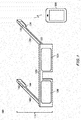
- Fig. 1 and Fig. 2 schematically illustrate one example of eyeglasses 100.
- Fig. 1 is a perspective view of the eyeglasses 100.
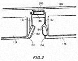
- Fig. 2 is a partially enlarged view of the eyeglasses 100 seen from behind.
- the eyeglasses 100 may be one example of an eyewear.
- the eyeglasses 100 includes a frame 110, a left lens 124 and a right lens 126.
- the frame 110 has a front 120, a left temple 130 and a right temple 140.
- the front 120 has: a rim 122 that holds the left lens 124 and the right lens 126; a left nose pad 152; a right nose pad 154 and a glabella electrode unit 200.
- the left nose pad 152 is supported by a support member 151 placed in the front 120.
- the support member 151 may be a linear member having one end that is placed in the front 120, and another end that supports the left nose pad 152.
- a left electrode 162 is placed on a front surface of the left nose pad 152. The left electrode 162 abuts on the nose of a wearer 10 when the wearer 10 who is to wear the eyeglasses 100 wears the eyeglasses 100.
- the right nose pad 154 is supported by a support member 153 placed in the front 120.
- the support member 153 may be a linear member having one end that is placed in the front 120, and another end that supports the right nose pad 154.
- a right electrode 164 is placed on a front surface of the right nose pad 154. The right electrode 164 abuts on the nose of the wearer 10 when the wearer 10 wears the eyeglasses 100.
- the glabella electrode unit 200 may be arranged to be positioned in front of the glabella of the wearer 10 when the wearer 10 wears the eyeglasses 100.
- a glabella electrode 166 is placed on a front surface of the glabella electrode unit 200.
- the glabella electrode 166 abuts on the glabella of the wearer 10 when the wearer 10 wears the eyeglasses 100.
- the glabella electrode unit 200 may be arranged at any position of the frame 110 as long as such a position can cause the glabella electrode 166 to abut on the glabella of the wearer 10.
- the glabella electrode unit 200 is placed for example in the bridge of the frame 110.
- the glabella electrode 166 may be one example of a first electrode.
- the left temple 130 has a circuit board 132 and an earth electrode 134.
- the earth electrode 134 is electrically connected to the circuit board 132.
- the earth electrode 134 may be arranged on a lower surface of the left temple 130.
- the earth electrode 134 may be arranged at a position at which it abuts on an upper portion of an ear of the wearer 10 when the wearer 10 wears the eyeglasses 100.
- the right temple 140 has a battery 142 and a reference electrode 144.
- the battery 142 is electrically connected to the circuit board 132 via the right temple 140, the front 120 and the left temple 130.
- a wire that electrically connects the battery 142 and the circuit board 132 is for example embedded in the frame 110.
- the battery 142 supplies electrical power to the circuit board 132.
- the reference electrode 144 may be arranged on a lower surface of the right temple 140.
- the reference electrode 144 may be arranged at a position at which it abuts on an upper portion of an ear of the wearer 10 when the wearer 10 wears the eyeglasses 100.
- the reference electrode 144 is electrically connected to the circuit board 132 via the right temple 140, the front 120 and the left temple 130.
- a wire that electrically connects the reference electrode 144 and the circuit board 132 is for example embedded in the frame 110.
- the left electrode 162 is electrically connected with the circuit board 132 via the left nose pad 152, the support member 151, the front 120 and the left temple 130.
- a wire that electrically connects the left electrode 162 and the circuit board 132 is for example embedded in the left nose pad 152, the support member 151, the front 120 and the left temple 130.
- the right electrode 164 is electrically connected with the circuit board 132 via the right nose pad 154, the support member 153, the front 120 and the left temple 130.
- a wire that electrically connects the right electrode 164 and the circuit board 132 is for example embedded in the right nose pad 154, the support member 153, the front 120 and the left temple 130.
- the left electrode 162 and the right electrode 164 may be one example of a pair of second electrodes.
- the glabella electrode 166 is electrically connected with the circuit board 132 via the glabella electrode unit 200, the front 120 and the left temple 130.
- the glabella electrode 166 is electrically connected with the glabella electrode unit 200.
- a wire that electrically connects the glabella electrode unit 200 and the circuit board 132 may be embedded in the front 120 and the left temple 130.
- the circuit board 132 may detect an eye potential by using the left electrode 162, the right electrode 164, the glabella electrode 166, the earth electrode 134 and the reference electrode 144.
- the circuit board 132 may be one example of an eye potential detecting unit.
- the circuit board 132 may process a detected eye potential.
- the circuit board 132 may process an eye potential by using electrical power supplied from the battery 142.
- Processing an eye potential may be performing arithmetic processing on the eye potential.
- the circuit board 132 performs adding and subtracting processing on an eye potential of the left electrode 162 relative to the glabella electrode 166 as its reference, and an eye potential of the right electrode 164 relative to the glabella electrode 166 as its reference.
- processing an eye potential may be performing signal amplification processing on the eye potential.
- processing an eye potential may be performing digitization processing on an eye potential signal.
- processing an eye potential may be transmitting the eye potential.
- the circuit board 132 transmits an eye potential to an information terminal 300.
- the circuit board 132 may transmit an eye potential to the information terminal 300 by wireless communication.
- the circuit board 132 transmits an eye potential to the information terminal 300 by using a wireless LAN such as Bluetooth (registered trademark), Wi-Fi (registered trademark) or the like.
- the information terminal 300 may be a mobile phone such as a smartphone, a tablet terminal, PC (Personal Computer) or the like.
- processing an eye potential may be, according to the eye potential, detecting a line of sight of a wearer of the eyeglasses 100, detecting a blink, detecting sleepiness, or the like.
- the circuit board 132 may transmit, to the information terminal 300, a detection result about a line of sight, a detection result about his/her blink, a detection result about his/her sleepiness, or the like.
- Fig. 3 schematically illustrates a state where the wearer 10 wears the eyeglasses 100.
- the glabella electrode 166 abuts on the glabella 12 of the wearer 10.
- the left electrode 162 abuts on a nose 14 of the wearer 10.
- the right electrode 164 also abuts on the nose 14 of the wearer 10.
- the left electrode 162, the right electrode 164 and the glabella electrode 166 desirably always keep surely abutting on the wearer 10 so as to continuously detect an eye potential of the wearer 10 while the wearer 10 wears the eyeglasses 100. Also, when an impact is applied to the eyeglasses 100, desirably the glabella electrode 166 is pushed onto the glabella 12 of the wearer 10, and thereby application of an excessive impact to the glabella 12 can be prevented.
- the glabella electrode unit 200 holds the glabella electrode 166 such that a distance between the frame 110 and the glabella electrode 166 is changeable.
- the glabella electrode unit 200 may be one example of an electrode holding unit.
- Fig. 4 schematically illustrates one example of the glabella electrode unit 200.
- the glabella electrode unit 200 may have an elastic member 210 and a wire 212.
- the elastic member 210 is placed in the frame 110, and holds the glabella electrode 166.
- the wire 212 electrically connects the glabella electrode 166, and a wire 150 embedded in the frame 110.
- the wire 150 electrically connects the wire 212 and the circuit board 132.
- the distance between the frame 110 and the glabella electrode 166 can be made changeable. For example, if the wearer 10 wears the eyeglasses 100 and the glabella electrode 166 is pushed onto the elastic member 210, the distance between the frame 110 and the glabella electrode 166 becomes short. In this manner, by the elastic member 210 holding the glabella electrode 166, even if relative positions of the wearer 10 and the eyeglasses 100 change, the elastic force of the elastic member 210 allows the glabella electrode 166 and the glabella 12 to remain abutting on each other.
- the glabella electrode units 200 are to be placed in respective ones among a plurality of pairs of eyeglasses worn by a plurality of the wearers 10, by the glabella electrode units 200 making changeable the distances between the frames 110 and the glabella electrodes 166, differences in distances between the glabellas 12 of the wearers 10 and the frames 110 can be absorbed for each wearer 10 among the plurality of wearers 10 and for each pair of eyeglasses among the plurality of pairs of eyeglasses. Also, if an impact is applied to the eyeglasses 100, the impact can be absorbed by the elastic member 210, and an impact to be applied to the glabella 12 can be reduced.
- the elastic member 210 may be any member as long as it has elasticity.
- the elastic member 210 is elastomer resin.
- Fig. 5 schematically illustrates another example of the glabella electrode unit 200.
- the glabella electrode unit 200 may have a conductive member 220 and a wire joining unit 222.
- the conductive member 220 and the wire joining unit 222 are placed in the frame 110.
- the conductive member 220 has elasticity and conductivity.
- the conductive member 220 holds the glabella electrode 166.
- the wire joining unit 222 electrically connects the conductive member 220 and the wire 150.
- the distance between the frame 110 and the glabella electrode 166 can be made changeable. For example, if the wearer 10 wears the eyeglasses 100 and the glabella electrode 166 is pushed onto the conductive member 220, the distance between the frame 110 and the glabella electrode 166 becomes short. In this manner, by the conductive member 220 holding the glabella electrode 166, even if relative positions of the wearer 10 and the eyeglasses 100 change, the elastic force of the conductive member 220 allows the glabella electrode 166 and the glabella 12 to remain abutting on each other. Also, if an impact is applied to the eyeglasses 100, the impact can be absorbed by the conductive member 220, and an impact to be applied to the glabella 12 can be reduced.
- the conductive member 220 may be any member as long as it has elasticity and conductivity.
- the conductive member 220 is conductive sponge.
- the conductive member 220 may be conductive rubber.
- the conductive member 220 may be conductive resin having elasticity.
- Fig. 6 schematically illustrates another example of the glabella electrode unit 200.
- the glabella electrode unit 200 may have a connector 230 and a connector 232.
- the connector 230 is placed in the frame 110.
- the connector 232 holds the glabella electrode 166.
- the glabella electrode 166 may be provided on a front surface of the connector 232.
- the connector 232 is attachable to and detachable from the connector 230, and electrically connects the glabella electrode 166 to the connector 230.
- the connector 230 electrically connects the glabella electrode 166 and the wire 150.
- the connector 230 may be one example of a first connector.
- the connector 232 may be one example of a second connector.
- a connector 234 with a height which is different from the height of the connector 232 may be coupled to the connector 230.
- the connector 234 may be one example of a second connector. Due to the connector 232 and the connector 234 with different heights being attachable to and detachable from the connector 230, the distance between the frame 110 and the glabella electrode 166 can be made changeable.
- the connector 230 and at least either of the connector 232 and the connector 234 may have elasticity. Thereby, if an impact is applied to the eyeglasses 100, the impact can be absorbed by the connector 230 and at least either of the connector 232 and the connector 234, and an impact to be applied to the glabella 12 can be reduced.
- Fig. 7 schematically illustrates another example of the glabella electrode unit 200.
- the glabella electrode unit 200 may have a first member 240 and a second member 242.
- the first member 240 is placed in the frame 110.
- the second member 242 holds the glabella electrode 166.
- the glabella electrode 166 may be provided on a front surface of the second member 242.
- the first member 240 holds the second member 242.
- the first member 240 and the second member 242 may be electrically connected at a contact portion between the first member 240 and the second member 242.
- the first member 240 may have a wire 241, and the second member 242 and the wire 150 may be electrically connected by the wire 241.
- the second member 242 and the glabella electrode 166 may be electrically connected.
- the glabella electrode 166 may be electrically connected to the wire 150 via the contact portion between the first member 240 and the second member 242, and the wire 241.
- the second member 242 moves relative to the first member 240.
- the first member 240 holds the second member 242 by a screw structure. Thereby, by rotating the second member 242, the distance between the frame 110 and the glabella electrode 166 can be changed.
- the first member 240 may hold the second member 242 such that if a certain degree (or higher degrees) of force is applied thereto, the distance between the frame 110 and the glabella electrode 166 changes stepwise.
- it has a structure in which the first member 240 locks the second member 242 with a plurality of steps, and if a certain degree (or higher degrees) of force is applied, the lock is unlocked. Thereby, the distance between the frame 110 and the glabella electrode 166 can be changed. Also, if an impact is applied to the eyeglasses 100, the second member 242 moves stepwise relative to the first member 240, and so the impact can be absorbed.
- the connector 230 and at least either of the connector 232 and the connector 234 may have elasticity. Thereby, if an impact is applied to the eyeglasses 100, the impact can be absorbed by the connector 230 and at least either of the connector 232 and the connector 234, and an impact to be applied to the glabella 12 can be reduced.
- the explanation in relation to Fig. 7 is about an example in which the first member 240 contains the second member 242, but this is not the only example.
- the second member 242 may contain the first member 240.
- Fig. 8 schematically illustrates another example of the glabella electrode unit 200.
- Fig. 8 exemplarily illustrates an example in which the second member 242 contains the first member 240.
- the explanation in the present embodiment is about an example in which the left temple 130 has the earth electrode 134, and the right temple 140 has the reference electrode 144, but the left temple 130 may have the reference electrode 144, and the right temple 140 may have the earth electrode 134. Also, the explanation in the present embodiment is about an example in which the left temple 130 has the circuit board 132, and the right temple 140 has the battery 142, but the left temple 130 may have the battery 142, and the right temple 140 may have the circuit board 132.
- the eyeglasses 100 that detect an eye potential is explained as one example of an eyewear, but this is not the only example.
- the eyewear may be any eyeglasses as long as they use an electrode.
- the eyewear is eyeglasses that processes a brain wave, eyeglasses that processes images, eyeglasses that processes sound, or the like.
- the eyeglasses 100 is explained as an example of an eyewear, but this is not the only example.
- the eyewear may be sunglasses, a head mount display, or the like.
- each part of the eyeglasses 100 illustrated in Fig. 1 to Fig. 3 is exemplary, and the shape is not limited to the one illustrated in the figures.
Landscapes
- Health & Medical Sciences (AREA)
- Life Sciences & Earth Sciences (AREA)
- Physics & Mathematics (AREA)
- General Health & Medical Sciences (AREA)
- Engineering & Computer Science (AREA)
- Ophthalmology & Optometry (AREA)
- Animal Behavior & Ethology (AREA)
- Veterinary Medicine (AREA)
- Heart & Thoracic Surgery (AREA)
- Medical Informatics (AREA)
- Molecular Biology (AREA)
- Surgery (AREA)
- Biomedical Technology (AREA)
- Biophysics (AREA)
- Public Health (AREA)
- Pathology (AREA)
- General Physics & Mathematics (AREA)
- Optics & Photonics (AREA)
- Acoustics & Sound (AREA)
- Otolaryngology (AREA)
- Physiology (AREA)
- Computer Networks & Wireless Communication (AREA)
- Eye Examination Apparatus (AREA)
- Eyeglasses (AREA)
- Measurement And Recording Of Electrical Phenomena And Electrical Characteristics Of The Living Body (AREA)
Claims (12)
- Lunettes (100), comprenant :une monture (110) ;une première électrode (166) qui est en butée contre la glabelle d'un porteur des lunettes ;les lunettes étant caractérisées en ce qu'elles comprennent en outre :une unité de support d'électrode (200) qui supporte la première électrode de sorte qu'une distance entre la monture et la première électrode soit variable,l'unité de support d'électrode comprenant :un premier élément (240) placé dans la monture ; etun second élément (242) qui est connecté électriquement au premier élément, et qui se déplace par rapport au premier élément, etla première électrode étant située sur une surface avant du second élément, etle premier élément supportant le second élément par une structure à vis de sorte qu'il soit possible de faire varier la distance entre la monture et la première électrode par rotation du second élément.
- Lunettes (100), comprenant :une monture (110) ;une première électrode (166) qui est en butée contre la glabelle d'un porteur des lunettes ;les lunettes étant caractérisées en ce qu'elles comprennent en outre :une unité de support d'électrode (200) qui supporte la première électrode de sorte qu'une distance entre la monture et la première électrode soit variable,l'unité de support d'électrode comprenant :un premier élément (240) placé dans la monture ; etun second élément (242) qui est connecté électriquement au premier élément, et qui se déplace par rapport au premier élément, etla première électrode étant située sur une surface avant du second élément, etle premier élément supportant le second élément de sorte que si un certain degré de force y est appliqué, la distance entre la monture et la première électrode varie par palier.
- Lunettes selon la revendication 2, dans lesquelles le premier élément (240) comprend une pluralité de paliers pour verrouiller le second élément, et une structure où le verrou est déverrouillé si un certain degré de force est appliqué.
- Lunettes (100), comprenant :une monture (110) ;une première électrode (166) qui est en butée contre la glabelle d'un porteur des lunettes ;les lunettes étant caractérisées en ce qu'elles comprennent en outre :une unité de support d'électrode (200) qui supporte la première électrode de sorte qu'une distance entre la monture et la première électrode soit variable,l'unité de support d'électrode comprenant :un premier connecteur (230) placé dans la monture ; etun deuxième connecteur (232) qui peut être attaché au premier connecteur et qui peut en être détaché, et qui connecte électriquement la première électrode au premier connecteur, etla première électrode étant située sur une surface avant du deuxième connecteur.
- Lunettes selon la revendication 4, comprenant en outre : à la place du deuxième connecteur (232) : un troisième connecteur (234) qui peut être attaché au premier connecteur (230) et qui peut en être détaché, et qui connecte électriquement la première électrode (166) au premier connecteur, le troisième connecteur ayant une hauteur différente de celle du deuxième connecteur,
le premier connecteur étant configuré pour se connecter de manière interchangeable au deuxième connecteur et au troisième connecteur ; et
la première électrode étant située sur une surface avant du troisième connecteur. - Lunettes selon la revendication 5, dans lesquelles au moins un des premier (230), deuxième (232) et troisième (234) connecteurs comprend un élément élastique (210) constitué d'un matériau conducteur.
- Lunettes selon l'une quelconque des revendications 1 à 6, dans lesquelles l'unité de support d'électrode (200) comprend un élément élastique (210).
- Lunettes selon la revendication 7, dans lesquelles l'élément élastique (210) comprend un élément conducteur connecté électriquement à la première électrode (230).
- Lunettes selon la revendication 8, dans lesquelles l'élément élastique (230) est une éponge conductrice, du caoutchouc conducteur ou une résine conductrice.
- Lunettes selon l'une quelconque des revendications 1 à 9, comprenant en outre :une paire de plaquettes de nez (152, 154) ; etune paire de secondes électrodes (162, 164) placées sur des surfaces avant de la paire de plaquettes de nez.
- Lunettes selon la revendication 10, comprenant en outre une unité de détection de potentiel d'oeil (132) qui est connectée électriquement à la première électrode et à la paire de secondes électrodes, et qui détecte un potentiel d'oeil du porteur.
- Ensemble lunettes comprenant :les lunettes (100) selon l'une quelconque des revendications 5 et 6 ;le deuxième connecteur (232) ; etle troisième connecteur (234).
Applications Claiming Priority (2)
| Application Number | Priority Date | Filing Date | Title |
|---|---|---|---|
| JP2014082796A JP6306926B2 (ja) | 2014-04-14 | 2014-04-14 | アイウエア |
| PCT/JP2015/061383 WO2015159862A1 (fr) | 2014-04-14 | 2015-04-13 | Lunettes |
Publications (3)
| Publication Number | Publication Date |
|---|---|
| EP3123928A1 EP3123928A1 (fr) | 2017-02-01 |
| EP3123928A4 EP3123928A4 (fr) | 2017-05-10 |
| EP3123928B1 true EP3123928B1 (fr) | 2018-10-31 |
Family
ID=54324068
Family Applications (1)
| Application Number | Title | Priority Date | Filing Date |
|---|---|---|---|
| EP15780095.4A Active EP3123928B1 (fr) | 2014-04-14 | 2015-04-13 | Lunettes |
Country Status (5)
| Country | Link |
|---|---|
| US (2) | US9883816B2 (fr) |
| EP (1) | EP3123928B1 (fr) |
| JP (1) | JP6306926B2 (fr) |
| CN (1) | CN106455970B (fr) |
| WO (1) | WO2015159862A1 (fr) |
Families Citing this family (13)
| Publication number | Priority date | Publication date | Assignee | Title |
|---|---|---|---|---|
| WO2017110908A1 (fr) * | 2015-12-22 | 2017-06-29 | 三井化学株式会社 | Lunettes électroniques |
| CN106094256A (zh) * | 2016-06-01 | 2016-11-09 | 宇龙计算机通信科技(深圳)有限公司 | 家居设备控制方法、家居设备控制装置和智能眼镜 |
| IT201600125471A1 (it) | 2016-12-13 | 2018-06-13 | Safilo Sa Fabbrica Italiana Lavorazione Occhiali Spa | Occhiali con bio-sensori |
| JP7257398B2 (ja) * | 2017-11-16 | 2023-04-13 | サフィーロ・ソシエタ・アツィオナリア・ファブリカ・イタリアナ・ラボラツィオーネ・オッチアリ・エス・ピー・エー | バイオセンサを備えた眼鏡 |
| CN108089326B (zh) | 2018-02-01 | 2023-12-26 | 北京七鑫易维信息技术有限公司 | 一种适配于与眼镜使用的装置 |
| JP6691928B2 (ja) * | 2018-02-07 | 2020-05-13 | 株式会社ジンズホールディングス | アイウエアセット及び信号処理ユニット |
| JP1634834S (fr) * | 2018-04-12 | 2019-06-24 | ||
| JP1623460S (fr) * | 2018-07-31 | 2020-01-27 | ||
| JP1623458S (fr) * | 2018-07-31 | 2020-01-27 | ||
| JP7236852B2 (ja) | 2018-12-03 | 2023-03-10 | 株式会社ジンズホールディングス | ノーズパッド及びアイウエア |
| USD908787S1 (en) * | 2019-01-30 | 2021-01-26 | Jins Holdings Inc. | Eyeglasses |
| US10659869B1 (en) * | 2019-02-08 | 2020-05-19 | Facebook Technologies, Llc | Cartilage transducer |
| CN110101387A (zh) * | 2019-04-30 | 2019-08-09 | 华南师范大学 | 一种护目镜控制器 |
Family Cites Families (14)
| Publication number | Priority date | Publication date | Assignee | Title |
|---|---|---|---|---|
| US4331163A (en) * | 1980-08-11 | 1982-05-25 | Haruo Nomura | Medical treatment glasses |
| JPH0712378B2 (ja) * | 1989-08-10 | 1995-02-15 | パイオニア株式会社 | 脳波誘導用ゴーグルおよび脳波誘導装置 |
| DE4022606A1 (de) * | 1990-05-22 | 1991-11-28 | Claus Peter Christ | Vorrichtung zur beobachtung und/oder registrierung der augenbewegungen |
| JP2998233B2 (ja) * | 1991-02-28 | 2000-01-11 | トヨタ自動車株式会社 | 可変焦点眼鏡 |
| US20040070729A1 (en) * | 2001-02-19 | 2004-04-15 | Peter Wiebe | Device and method for determining the viewing direction in terms of a fix reference co-ordinates system |
| JP2005205024A (ja) * | 2004-01-23 | 2005-08-04 | Sumitomo Rubber Ind Ltd | 眼球運動測定方法および測定装置 |
| EP1671670A1 (fr) * | 2004-12-14 | 2006-06-21 | STX Sprl | Appareil pour l'electro-inhibition des muscles de la face |
| JP4652489B2 (ja) * | 2009-01-19 | 2011-03-16 | パナソニック株式会社 | 脳波インタフェースシステムのための起動装置、方法およびコンピュータプログラム |
| CN201477288U (zh) * | 2009-07-29 | 2010-05-19 | 比亚迪股份有限公司 | 一种头戴显示器 |
| DE102010027201B4 (de) * | 2010-01-15 | 2014-05-08 | Okuvision Gmbh | Vorrichtung zur Elektrostimulation |
| CN202096374U (zh) * | 2010-12-15 | 2012-01-04 | 南开大学 | 基于眼电信号和头部运动信号的智能轮椅 |
| JP5661067B2 (ja) * | 2012-05-29 | 2015-01-28 | 株式会社ジェイアイエヌ | アイウエア |
| EP2981326B1 (fr) * | 2013-03-15 | 2018-05-23 | Neurolief Ltd. | Casque pour le traitement et l'évaluation de pathologies médicales |
| US9398864B2 (en) * | 2014-03-12 | 2016-07-26 | The Nielsen Company (Us), Llc | Methods and apparatus to gather and analyze electroencephalographic data |
-
2014
- 2014-04-14 JP JP2014082796A patent/JP6306926B2/ja active Active
-
2015
- 2015-04-13 WO PCT/JP2015/061383 patent/WO2015159862A1/fr active Application Filing
- 2015-04-13 CN CN201580019440.4A patent/CN106455970B/zh active Active
- 2015-04-13 EP EP15780095.4A patent/EP3123928B1/fr active Active
-
2016
- 2016-10-13 US US15/292,139 patent/US9883816B2/en active Active
-
2018
- 2018-02-04 US US15/888,062 patent/US10123719B2/en active Active
Non-Patent Citations (1)
| Title |
|---|
| None * |
Also Published As
| Publication number | Publication date |
|---|---|
| CN106455970B (zh) | 2018-05-29 |
| US20180160973A1 (en) | 2018-06-14 |
| WO2015159862A1 (fr) | 2015-10-22 |
| JP6306926B2 (ja) | 2018-04-04 |
| CN106455970A (zh) | 2017-02-22 |
| EP3123928A4 (fr) | 2017-05-10 |
| JP2015202187A (ja) | 2015-11-16 |
| US10123719B2 (en) | 2018-11-13 |
| US9883816B2 (en) | 2018-02-06 |
| EP3123928A1 (fr) | 2017-02-01 |
| US20170027470A1 (en) | 2017-02-02 |
Similar Documents
| Publication | Publication Date | Title |
|---|---|---|
| EP3123928B1 (fr) | Lunettes | |
| EP2668898B1 (fr) | Lunettes | |
| CN110115560B (zh) | 眼具套件及信号处理单元 | |
| WO2016052168A1 (fr) | Dispositif de détection de caractéristiques physiques et dispositif électronique de type lunettes | |
| WO2015159851A1 (fr) | Unité de détection, lunettes et système de détection de potentiel oculaire | |
| JP2015202197A (ja) | 眼電位情報処理装置、眼電位情報処理システム、装着具及びプログラム | |
| JP2015202183A (ja) | 検出制御装置、装着具、眼電位情報処理システム、及びプログラム | |
| JP2015202198A (ja) | アイウエア | |
| JP2017185148A (ja) | ウェアラブル生体計測装置 | |
| JP6932007B2 (ja) | 情報処理方法、情報処理装置及びプログラム | |
| TWI610656B (zh) | 穿戴式生理監測裝置 | |
| JP2015202199A (ja) | 眼電位情報処理装置、眼電位情報処理システム、装着具及びプログラム | |
| WO2015159858A1 (fr) | Lunettes | |
| JP5689206B1 (ja) | アイウエア | |
| JP2015202188A (ja) | アイウエア | |
| CA2824972A1 (fr) | Lunettes | |
| JP6266417B2 (ja) | 情報処理装置、情報処理システム、及びプログラム | |
| JP2015205030A (ja) | アイウエア | |
| US20210041723A1 (en) | Eyewear system |
Legal Events
| Date | Code | Title | Description |
|---|---|---|---|
| STAA | Information on the status of an ep patent application or granted ep patent |
Free format text: STATUS: THE INTERNATIONAL PUBLICATION HAS BEEN MADE |
|
| PUAI | Public reference made under article 153(3) epc to a published international application that has entered the european phase |
Free format text: ORIGINAL CODE: 0009012 |
|
| STAA | Information on the status of an ep patent application or granted ep patent |
Free format text: STATUS: REQUEST FOR EXAMINATION WAS MADE |
|
| 17P | Request for examination filed |
Effective date: 20161026 |
|
| AK | Designated contracting states |
Kind code of ref document: A1 Designated state(s): AL AT BE BG CH CY CZ DE DK EE ES FI FR GB GR HR HU IE IS IT LI LT LU LV MC MK MT NL NO PL PT RO RS SE SI SK SM TR |
|
| AX | Request for extension of the european patent |
Extension state: BA ME |
|
| A4 | Supplementary search report drawn up and despatched |
Effective date: 20170406 |
|
| RIC1 | Information provided on ipc code assigned before grant |
Ipc: G02C 11/00 20060101ALI20170401BHEP Ipc: A61B 3/10 20060101AFI20170401BHEP Ipc: A61B 5/0496 20060101ALI20170401BHEP Ipc: A61B 3/113 20060101ALN20170401BHEP Ipc: A61B 5/00 20060101ALI20170401BHEP |
|
| DAV | Request for validation of the european patent (deleted) | ||
| DAX | Request for extension of the european patent (deleted) | ||
| GRAP | Despatch of communication of intention to grant a patent |
Free format text: ORIGINAL CODE: EPIDOSNIGR1 |
|
| STAA | Information on the status of an ep patent application or granted ep patent |
Free format text: STATUS: GRANT OF PATENT IS INTENDED |
|
| RIC1 | Information provided on ipc code assigned before grant |
Ipc: A61B 5/0496 20060101ALI20180419BHEP Ipc: G02C 11/00 20060101ALI20180419BHEP Ipc: A61B 3/10 20060101AFI20180419BHEP Ipc: A61B 3/113 20060101ALN20180419BHEP Ipc: A61B 5/00 20060101ALI20180419BHEP |
|
| INTG | Intention to grant announced |
Effective date: 20180517 |
|
| GRAS | Grant fee paid |
Free format text: ORIGINAL CODE: EPIDOSNIGR3 |
|
| GRAA | (expected) grant |
Free format text: ORIGINAL CODE: 0009210 |
|
| STAA | Information on the status of an ep patent application or granted ep patent |
Free format text: STATUS: THE PATENT HAS BEEN GRANTED |
|
| AK | Designated contracting states |
Kind code of ref document: B1 Designated state(s): AL AT BE BG CH CY CZ DE DK EE ES FI FR GB GR HR HU IE IS IT LI LT LU LV MC MK MT NL NO PL PT RO RS SE SI SK SM TR |
|
| REG | Reference to a national code |
Ref country code: CH Ref legal event code: EP Ref country code: GB Ref legal event code: FG4D |
|
| REG | Reference to a national code |
Ref country code: AT Ref legal event code: REF Ref document number: 1058394 Country of ref document: AT Kind code of ref document: T Effective date: 20181115 |
|
| REG | Reference to a national code |
Ref country code: DE Ref legal event code: R096 Ref document number: 602015019223 Country of ref document: DE |
|
| REG | Reference to a national code |
Ref country code: IE Ref legal event code: FG4D |
|
| REG | Reference to a national code |
Ref country code: NL Ref legal event code: MP Effective date: 20181031 |
|
| REG | Reference to a national code |
Ref country code: LT Ref legal event code: MG4D |
|
| REG | Reference to a national code |
Ref country code: AT Ref legal event code: MK05 Ref document number: 1058394 Country of ref document: AT Kind code of ref document: T Effective date: 20181031 |
|
| PG25 | Lapsed in a contracting state [announced via postgrant information from national office to epo] |
Ref country code: AT Free format text: LAPSE BECAUSE OF FAILURE TO SUBMIT A TRANSLATION OF THE DESCRIPTION OR TO PAY THE FEE WITHIN THE PRESCRIBED TIME-LIMIT Effective date: 20181031 Ref country code: LV Free format text: LAPSE BECAUSE OF FAILURE TO SUBMIT A TRANSLATION OF THE DESCRIPTION OR TO PAY THE FEE WITHIN THE PRESCRIBED TIME-LIMIT Effective date: 20181031 Ref country code: IS Free format text: LAPSE BECAUSE OF FAILURE TO SUBMIT A TRANSLATION OF THE DESCRIPTION OR TO PAY THE FEE WITHIN THE PRESCRIBED TIME-LIMIT Effective date: 20190228 Ref country code: HR Free format text: LAPSE BECAUSE OF FAILURE TO SUBMIT A TRANSLATION OF THE DESCRIPTION OR TO PAY THE FEE WITHIN THE PRESCRIBED TIME-LIMIT Effective date: 20181031 Ref country code: PL Free format text: LAPSE BECAUSE OF FAILURE TO SUBMIT A TRANSLATION OF THE DESCRIPTION OR TO PAY THE FEE WITHIN THE PRESCRIBED TIME-LIMIT Effective date: 20181031 Ref country code: FI Free format text: LAPSE BECAUSE OF FAILURE TO SUBMIT A TRANSLATION OF THE DESCRIPTION OR TO PAY THE FEE WITHIN THE PRESCRIBED TIME-LIMIT Effective date: 20181031 Ref country code: BG Free format text: LAPSE BECAUSE OF FAILURE TO SUBMIT A TRANSLATION OF THE DESCRIPTION OR TO PAY THE FEE WITHIN THE PRESCRIBED TIME-LIMIT Effective date: 20190131 Ref country code: ES Free format text: LAPSE BECAUSE OF FAILURE TO SUBMIT A TRANSLATION OF THE DESCRIPTION OR TO PAY THE FEE WITHIN THE PRESCRIBED TIME-LIMIT Effective date: 20181031 Ref country code: LT Free format text: LAPSE BECAUSE OF FAILURE TO SUBMIT A TRANSLATION OF THE DESCRIPTION OR TO PAY THE FEE WITHIN THE PRESCRIBED TIME-LIMIT Effective date: 20181031 Ref country code: NO Free format text: LAPSE BECAUSE OF FAILURE TO SUBMIT A TRANSLATION OF THE DESCRIPTION OR TO PAY THE FEE WITHIN THE PRESCRIBED TIME-LIMIT Effective date: 20190131 |
|
| PG25 | Lapsed in a contracting state [announced via postgrant information from national office to epo] |
Ref country code: PT Free format text: LAPSE BECAUSE OF FAILURE TO SUBMIT A TRANSLATION OF THE DESCRIPTION OR TO PAY THE FEE WITHIN THE PRESCRIBED TIME-LIMIT Effective date: 20190301 Ref country code: NL Free format text: LAPSE BECAUSE OF FAILURE TO SUBMIT A TRANSLATION OF THE DESCRIPTION OR TO PAY THE FEE WITHIN THE PRESCRIBED TIME-LIMIT Effective date: 20181031 Ref country code: SE Free format text: LAPSE BECAUSE OF FAILURE TO SUBMIT A TRANSLATION OF THE DESCRIPTION OR TO PAY THE FEE WITHIN THE PRESCRIBED TIME-LIMIT Effective date: 20181031 Ref country code: RS Free format text: LAPSE BECAUSE OF FAILURE TO SUBMIT A TRANSLATION OF THE DESCRIPTION OR TO PAY THE FEE WITHIN THE PRESCRIBED TIME-LIMIT Effective date: 20181031 Ref country code: AL Free format text: LAPSE BECAUSE OF FAILURE TO SUBMIT A TRANSLATION OF THE DESCRIPTION OR TO PAY THE FEE WITHIN THE PRESCRIBED TIME-LIMIT Effective date: 20181031 Ref country code: GR Free format text: LAPSE BECAUSE OF FAILURE TO SUBMIT A TRANSLATION OF THE DESCRIPTION OR TO PAY THE FEE WITHIN THE PRESCRIBED TIME-LIMIT Effective date: 20190201 |
|
| PG25 | Lapsed in a contracting state [announced via postgrant information from national office to epo] |
Ref country code: DK Free format text: LAPSE BECAUSE OF FAILURE TO SUBMIT A TRANSLATION OF THE DESCRIPTION OR TO PAY THE FEE WITHIN THE PRESCRIBED TIME-LIMIT Effective date: 20181031 Ref country code: CZ Free format text: LAPSE BECAUSE OF FAILURE TO SUBMIT A TRANSLATION OF THE DESCRIPTION OR TO PAY THE FEE WITHIN THE PRESCRIBED TIME-LIMIT Effective date: 20181031 Ref country code: IT Free format text: LAPSE BECAUSE OF FAILURE TO SUBMIT A TRANSLATION OF THE DESCRIPTION OR TO PAY THE FEE WITHIN THE PRESCRIBED TIME-LIMIT Effective date: 20181031 |
|
| REG | Reference to a national code |
Ref country code: DE Ref legal event code: R097 Ref document number: 602015019223 Country of ref document: DE |
|
| PG25 | Lapsed in a contracting state [announced via postgrant information from national office to epo] |
Ref country code: SK Free format text: LAPSE BECAUSE OF FAILURE TO SUBMIT A TRANSLATION OF THE DESCRIPTION OR TO PAY THE FEE WITHIN THE PRESCRIBED TIME-LIMIT Effective date: 20181031 Ref country code: SM Free format text: LAPSE BECAUSE OF FAILURE TO SUBMIT A TRANSLATION OF THE DESCRIPTION OR TO PAY THE FEE WITHIN THE PRESCRIBED TIME-LIMIT Effective date: 20181031 Ref country code: EE Free format text: LAPSE BECAUSE OF FAILURE TO SUBMIT A TRANSLATION OF THE DESCRIPTION OR TO PAY THE FEE WITHIN THE PRESCRIBED TIME-LIMIT Effective date: 20181031 Ref country code: RO Free format text: LAPSE BECAUSE OF FAILURE TO SUBMIT A TRANSLATION OF THE DESCRIPTION OR TO PAY THE FEE WITHIN THE PRESCRIBED TIME-LIMIT Effective date: 20181031 |
|
| PLBE | No opposition filed within time limit |
Free format text: ORIGINAL CODE: 0009261 |
|
| STAA | Information on the status of an ep patent application or granted ep patent |
Free format text: STATUS: NO OPPOSITION FILED WITHIN TIME LIMIT |
|
| REG | Reference to a national code |
Ref country code: DE Ref legal event code: R082 Ref document number: 602015019223 Country of ref document: DE Representative=s name: DENNEMEYER & ASSOCIATES S.A., LU Ref country code: DE Ref legal event code: R081 Ref document number: 602015019223 Country of ref document: DE Owner name: JINS HOLDINGS INC., MAEBASHI-SHI, JP Free format text: FORMER OWNER: JIN CO., LTD., MAEBASHI-SHI, GUNMA, JP |
|
| 26N | No opposition filed |
Effective date: 20190801 |
|
| PG25 | Lapsed in a contracting state [announced via postgrant information from national office to epo] |
Ref country code: SI Free format text: LAPSE BECAUSE OF FAILURE TO SUBMIT A TRANSLATION OF THE DESCRIPTION OR TO PAY THE FEE WITHIN THE PRESCRIBED TIME-LIMIT Effective date: 20181031 |
|
| REG | Reference to a national code |
Ref country code: CH Ref legal event code: PL |
|
| REG | Reference to a national code |
Ref country code: BE Ref legal event code: MM Effective date: 20190430 |
|
| PG25 | Lapsed in a contracting state [announced via postgrant information from national office to epo] |
Ref country code: LU Free format text: LAPSE BECAUSE OF NON-PAYMENT OF DUE FEES Effective date: 20190413 Ref country code: MC Free format text: LAPSE BECAUSE OF FAILURE TO SUBMIT A TRANSLATION OF THE DESCRIPTION OR TO PAY THE FEE WITHIN THE PRESCRIBED TIME-LIMIT Effective date: 20181031 |
|
| PG25 | Lapsed in a contracting state [announced via postgrant information from national office to epo] |
Ref country code: CH Free format text: LAPSE BECAUSE OF NON-PAYMENT OF DUE FEES Effective date: 20190430 Ref country code: LI Free format text: LAPSE BECAUSE OF NON-PAYMENT OF DUE FEES Effective date: 20190430 |
|
| PG25 | Lapsed in a contracting state [announced via postgrant information from national office to epo] |
Ref country code: BE Free format text: LAPSE BECAUSE OF NON-PAYMENT OF DUE FEES Effective date: 20190430 |
|
| PG25 | Lapsed in a contracting state [announced via postgrant information from national office to epo] |
Ref country code: TR Free format text: LAPSE BECAUSE OF FAILURE TO SUBMIT A TRANSLATION OF THE DESCRIPTION OR TO PAY THE FEE WITHIN THE PRESCRIBED TIME-LIMIT Effective date: 20181031 |
|
| PG25 | Lapsed in a contracting state [announced via postgrant information from national office to epo] |
Ref country code: IE Free format text: LAPSE BECAUSE OF NON-PAYMENT OF DUE FEES Effective date: 20190413 |
|
| PG25 | Lapsed in a contracting state [announced via postgrant information from national office to epo] |
Ref country code: CY Free format text: LAPSE BECAUSE OF FAILURE TO SUBMIT A TRANSLATION OF THE DESCRIPTION OR TO PAY THE FEE WITHIN THE PRESCRIBED TIME-LIMIT Effective date: 20181031 |
|
| PG25 | Lapsed in a contracting state [announced via postgrant information from national office to epo] |
Ref country code: HU Free format text: LAPSE BECAUSE OF FAILURE TO SUBMIT A TRANSLATION OF THE DESCRIPTION OR TO PAY THE FEE WITHIN THE PRESCRIBED TIME-LIMIT; INVALID AB INITIO Effective date: 20150413 Ref country code: MT Free format text: LAPSE BECAUSE OF FAILURE TO SUBMIT A TRANSLATION OF THE DESCRIPTION OR TO PAY THE FEE WITHIN THE PRESCRIBED TIME-LIMIT Effective date: 20181031 |
|
| PG25 | Lapsed in a contracting state [announced via postgrant information from national office to epo] |
Ref country code: MK Free format text: LAPSE BECAUSE OF FAILURE TO SUBMIT A TRANSLATION OF THE DESCRIPTION OR TO PAY THE FEE WITHIN THE PRESCRIBED TIME-LIMIT Effective date: 20181031 |
|
| PGFP | Annual fee paid to national office [announced via postgrant information from national office to epo] |
Ref country code: FR Payment date: 20230424 Year of fee payment: 9 Ref country code: DE Payment date: 20220620 Year of fee payment: 9 |
|
| PGFP | Annual fee paid to national office [announced via postgrant information from national office to epo] |
Ref country code: GB Payment date: 20230419 Year of fee payment: 9 |