EP3123177B1 - Probenwähler - Google Patents
Probenwähler Download PDFInfo
- Publication number
- EP3123177B1 EP3123177B1 EP15713058.4A EP15713058A EP3123177B1 EP 3123177 B1 EP3123177 B1 EP 3123177B1 EP 15713058 A EP15713058 A EP 15713058A EP 3123177 B1 EP3123177 B1 EP 3123177B1
- Authority
- EP
- European Patent Office
- Prior art keywords
- sample
- sample container
- pusher member
- gripper
- transfer arm
- Prior art date
- Legal status (The legal status is an assumption and is not a legal conclusion. Google has not performed a legal analysis and makes no representation as to the accuracy of the status listed.)
- Active
Links
- 238000012546 transfer Methods 0.000 claims description 90
- 230000033001 locomotion Effects 0.000 claims description 14
- 238000002955 isolation Methods 0.000 claims description 11
- 230000000694 effects Effects 0.000 claims description 6
- 238000007789 sealing Methods 0.000 claims description 5
- 238000000034 method Methods 0.000 claims 3
- 230000035515 penetration Effects 0.000 claims 2
- 230000007246 mechanism Effects 0.000 description 8
- 230000004888 barrier function Effects 0.000 description 7
- 238000003780 insertion Methods 0.000 description 6
- 230000037431 insertion Effects 0.000 description 6
- 238000005057 refrigeration Methods 0.000 description 6
- 230000008878 coupling Effects 0.000 description 5
- 238000010168 coupling process Methods 0.000 description 5
- 238000005859 coupling reaction Methods 0.000 description 5
- YBGRCYCEEDOTDH-JYNQXTMKSA-N evap protocol Chemical compound O=C1C=C[C@]2(C)[C@H]3[C@@H](O)C[C@](C)([C@@](CC4)(O)C(=O)CO)[C@@H]4[C@@H]3CCC2=C1.O([C@H]1C[C@@](O)(CC=2C(O)=C3C(=O)C=4C=CC=C(C=4C(=O)C3=C(O)C=21)OC)C(=O)CO)[C@H]1C[C@H](N)[C@H](O)[C@H](C)O1.COC1=C(O)C(OC)=CC([C@@H]2C3=CC=4OCOC=4C=C3C(O[C@H]3[C@@H]([C@@H](O)[C@@H]4O[C@H](C)OC[C@H]4O3)O)[C@@H]3[C@@H]2C(OC3)=O)=C1.C([C@H](C[C@]1(C(=O)OC)C=2C(=C3C([C@]45[C@H]([C@@]([C@H](OC(C)=O)[C@]6(CC)C=CCN([C@H]56)CC4)(O)C(=O)OC)N3C)=CC=2)OC)C[C@@](C2)(O)CC)N2CCC2=C1NC1=CC=CC=C21 YBGRCYCEEDOTDH-JYNQXTMKSA-N 0.000 description 4
- 239000000463 material Substances 0.000 description 3
- 230000005540 biological transmission Effects 0.000 description 2
- 230000007613 environmental effect Effects 0.000 description 2
- 230000005484 gravity Effects 0.000 description 2
- 230000014759 maintenance of location Effects 0.000 description 2
- 229910001172 neodymium magnet Inorganic materials 0.000 description 2
- 239000011449 brick Substances 0.000 description 1
- 238000004891 communication Methods 0.000 description 1
- 238000001816 cooling Methods 0.000 description 1
- 238000007791 dehumidification Methods 0.000 description 1
- 238000011161 development Methods 0.000 description 1
- 230000018109 developmental process Effects 0.000 description 1
- 238000010586 diagram Methods 0.000 description 1
- 239000006260 foam Substances 0.000 description 1
- 238000007710 freezing Methods 0.000 description 1
- 230000008014 freezing Effects 0.000 description 1
- 238000013507 mapping Methods 0.000 description 1
- 239000012811 non-conductive material Substances 0.000 description 1
- 238000004080 punching Methods 0.000 description 1
- 230000001846 repelling effect Effects 0.000 description 1
- 239000000126 substance Substances 0.000 description 1
- 238000011179 visual inspection Methods 0.000 description 1
Images


Classifications
-
- G—PHYSICS
- G01—MEASURING; TESTING
- G01N—INVESTIGATING OR ANALYSING MATERIALS BY DETERMINING THEIR CHEMICAL OR PHYSICAL PROPERTIES
- G01N35/00—Automatic analysis not limited to methods or materials provided for in any single one of groups G01N1/00 - G01N33/00; Handling materials therefor
- G01N35/02—Automatic analysis not limited to methods or materials provided for in any single one of groups G01N1/00 - G01N33/00; Handling materials therefor using a plurality of sample containers moved by a conveyor system past one or more treatment or analysis stations
- G01N35/026—Automatic analysis not limited to methods or materials provided for in any single one of groups G01N1/00 - G01N33/00; Handling materials therefor using a plurality of sample containers moved by a conveyor system past one or more treatment or analysis stations having blocks or racks of reaction cells or cuvettes
-
- B—PERFORMING OPERATIONS; TRANSPORTING
- B65—CONVEYING; PACKING; STORING; HANDLING THIN OR FILAMENTARY MATERIAL
- B65G—TRANSPORT OR STORAGE DEVICES, e.g. CONVEYORS FOR LOADING OR TIPPING, SHOP CONVEYOR SYSTEMS OR PNEUMATIC TUBE CONVEYORS
- B65G1/00—Storing articles, individually or in orderly arrangement, in warehouses or magazines
- B65G1/02—Storage devices
- B65G1/04—Storage devices mechanical
- B65G1/137—Storage devices mechanical with arrangements or automatic control means for selecting which articles are to be removed
-
- G—PHYSICS
- G01—MEASURING; TESTING
- G01N—INVESTIGATING OR ANALYSING MATERIALS BY DETERMINING THEIR CHEMICAL OR PHYSICAL PROPERTIES
- G01N35/00—Automatic analysis not limited to methods or materials provided for in any single one of groups G01N1/00 - G01N33/00; Handling materials therefor
- G01N35/0099—Automatic analysis not limited to methods or materials provided for in any single one of groups G01N1/00 - G01N33/00; Handling materials therefor comprising robots or similar manipulators
-
- G—PHYSICS
- G01—MEASURING; TESTING
- G01N—INVESTIGATING OR ANALYSING MATERIALS BY DETERMINING THEIR CHEMICAL OR PHYSICAL PROPERTIES
- G01N35/00—Automatic analysis not limited to methods or materials provided for in any single one of groups G01N1/00 - G01N33/00; Handling materials therefor
- G01N35/02—Automatic analysis not limited to methods or materials provided for in any single one of groups G01N1/00 - G01N33/00; Handling materials therefor using a plurality of sample containers moved by a conveyor system past one or more treatment or analysis stations
- G01N35/04—Details of the conveyor system
- G01N2035/046—General conveyor features
- G01N2035/0465—Loading or unloading the conveyor
Definitions
- the exemplary embodiments generally relate to sample picking mechanisms and, more particularly, to sample picking mechanisms for use within storage and retrieval systems used to store and retrieve samples.
- samples such as biological or chemical samples
- storage of samples may be stored at or below freezing temperatures.
- the samples are stored at ultra-low temperatures ranging, for example, between about -50°C to about -90°C or at cryogenic temperatures ranging, for example, between about -140°C to about -196°C.
- ultra-low temperature shall mean temperatures below -50°C and above temperatures generally considered to be cryogenic.
- a mechanical robot is used to place and retrieve samples from the ultra-low temperature sample storage environment.
- Examples of such apparatuses operating in low temperatures for sample storage can be found in the following documents: US2012/060514A1 , US2007/172396A1 , US2012/283867A1 , US2010/028214A1 .
- the ultra-low temperature environment may be too cold for reliable operation of conventional sample picking mechanisms.
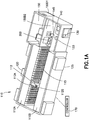
- Fig. 1A illustrates a sample storage facility or cold store 100 in accordance with aspects of the disclosed embodiment.
- the sample storage facility 100 may include any suitable number of environmental zones or areas that may be isolated from one another.
- the sample storage facility 100 may include one or more ultra-low temperature storage zones 110A, 110B, a transport zone 145 and a climate controlled antechamber 150.
- the sample storage facility 100 may have any suitable number and type of zones/areas in which samples are stored and/or transported and which may be accessed by storage facility personnel.
- the transport zone 145 may include an input/output module 130, a transport shuttle 112 and one or more sample selector modules 200 where the sample selector modules are disposed at least partly within the transport zone 145 as will be described below.
- the input/output module 130 may allow transfer of samples and/or sample trays to and from the sample storage facility 100 while maintaining a predetermined temperature within the transport zone 145.
- the sample selector modules 200 which will be described in greater detail below, may provide sorting capability for moving samples/sample holders within or between standard density (SD) and/or high density (HD) sample racks/trays.
- the transport zone 145 may be maintained at any suitable low temperature, such as about -20°C, in which a transport shuttle 112 and/or other automation may operate to transfer sample trays between the ultra-low temperature storage zones 110A, 110B, the sample selector modules 200 and the input/output module 130.
- the transport shuttle 112 may interface with a tile wall 115 where each tile is arranged to create, for example, a robotically friendly insulating closure of the ultra-low temperature zones 110A, 110B for removing sample trays from the ultra-low temperature zones 110A, 110B in any suitable manner.
- the transport shuttle 112 may be configured to transport the sample trays between the ultra-low temperature zones 110A, 110B and any other components of the sample storage facility as described herein, which may include but is not limited to transport of sample trays to and from the sample selector modules 200.
- the climate controlled antechamber 150 may include doors 150D1, 150D2 for providing personnel access to the at least the transport zone 145 and/or to the sample selector modules 200, at least part of which may be disposed within the climate controlled antechamber 150 (e.g. the sample selector modules 200 may be mounted through a wall separating/isolating the antechamber 150 from the transport zone 145.
- the climate controlled antechamber 150 may be maintained at any suitable temperature allowing for human entry into the antechamber 150.
- the sample storage facility 100 may include any suitable refrigeration system(s) 125 and/or dehumidification system(s) 120 for maintaining respective predetermined temperatures within the different zones of the sample storage facility 100.
- the transport zone 145, transport shuttle 112, tile wall 115, ultra-low temperature storage zones 110A, 110B, transport zone 145 and input/output modules of the sample storage facility 100 may be substantially similar to those described in United States patent numbers 7,635,246 issued on December 22, 2009 , 7,648,321 issued on January 19, 2010 , 7,793,842 issued on September 14, 2010 , 8,252,232 issued on August 28, 2012 and United States patent application numbers 13/595,817 filed on August 27, 2012 and 13/334,619 filed on December 22, 2011 .
- Fig. 1B illustrates a sample storage facility 100' in accordance with aspects of the disclosed embodiment.
- the sample storage facility 100' may be substantially similar to sample storage facility 100 described above and include any suitable number of environmental zones or areas 110A, 110B, 145 that may be isolated from one another.
- one or more sample selector modules 200 may be mounted through an exterior wall of the sample storage facility 100' rather than through a wall separating/isolating the antechamber 150 from the transport zone 145 or any other suitable zone of the sample storage facility 100.
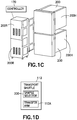
- Fig. 1C is a schematic illustration of sample selector modules 200. As may be realized, any suitable number of sample selector modules (two are shown in Fig. 1C ) may be stacked one above the other as shown in Figs. 1B and 1C or disposed side by side as illustrated in Fig. 1A . Each sample selector module 200 may be connected to or otherwise include any suitable refrigeration system 200R configured to maintain at least a portion of an interior of the sample selector at a predetermined ultra-low temperature as will be described below.
- each sample selector module 200 may have a respective refrigeration system 200R while in other aspects a common refrigeration system may be provided for two or more sample selector modules 200 or the sample selector module(s) may share a common refrigeration system with other components (such as ultra-low temperature storage zones 110A, 110B) of the sample storage facility 100, 100'.
- a common refrigeration system may be provided for two or more sample selector modules 200 or the sample selector module(s) may share a common refrigeration system with other components (such as ultra-low temperature storage zones 110A, 110B) of the sample storage facility 100, 100'.
- one or more sample selector modules 200 may be mounted to, for example, the transport shuttle 112 so that the one or more sample selectors 200 move as a unit with transport shuttle 112.
- the transport shuttle 112 may include a transfer arm 112A configured to remove sample trays from the ultra-low temperature zones 110A, 110B (or any other suitable location of the sample storage facility 100, 100') and place the sample trays within the one or more sample selector modules 200 disposed on the transport shuttle 112.
- One or more samples from the samples trays may be sorted and/or transferred to a different tray, such as between source and destination trays, within the ultra-low temperature environment of the sample selector module 200 allowing the source tray to be placed back into the ultra-low temperature zone 110A, 110B.
- the sample storage zone is the same temperature in which the transport shuttle 112 operates the sample selector 200 may not have a temperature controlled environment (e.g. such as the ultra-low temperature environment) but may be open to the transport shuttle operating environment.
- Any suitable controller 170 may be connected to the sample storage facility 100, 100' in any suitable manner, such as through a wired or wireless connection.
- the controller 170 may be configured to control the operation of the sample storage facility 100, 100'.
- the controller 170 may include any suitable memory and processors and be configured to track which samples are inserted and/or removed from the sample storage facility 100 and a location of each sample within the sample storage facility 100.
- the controller 170 may also be configured to control automation within the sample storage facility where the automation includes, but is not limited to, the transport shuttle 112 and sample selector modules 200 to transfer samples as described herein.
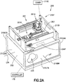
- each sample selector module 200 includes a frame 210F, at least one transfer device or unit 201A, 201B having a drive section 201 connected to the frame 210F and at least one transfer arm portion 400A (see Figs. 4 and 4A ) rotatably connected to the drive section 201.
- the frame 210F may include a cover portion 210C and a base portion 210B or include any suitable number of panels/walls (or a unitary/one piece panel) that form/forms a housing 200H configured to hold at least one isolated or sealed environment therein.
- the housing 200H may include a longitudinal axis LON and a lateral axis LAT and may be divided into isolated zones/areas.
- the base portion 210B includes lateral walls 210LTA, 210LTB, longitudinal walls 210LNA, 210LNB, a bottom wall 210BW and an isolation member 263 disposed opposite to and spaced apart from the bottom wall 210BW (the term "bottom” is used herein for exemplary purposes only and in other aspects any suitable spatial identifiers may be associated with the wall 210BW) so as to form an isolated climate controlled chamber or zone 223.
- the isolated climate controlled chamber 223 may be maintained at an ultra-low temperature, such as for example, about -80°C or any other suitable ultra-low temperature.
- the isolated climate controlled chamber 223 may be actively cooled while in other aspects the isolated climate controlled chamber 223 may be cooled in any suitable manner.
- One or more evaporators EVAP may be disposed within the isolated climate controlled chamber 223 and be configured to maintain, for example, a uniform ultra-cold temperature distribution within the isolated climate controlled chamber 223.
- the one or more evaporators EVAP may be disposed on a surface of the isolation member 263 forming an interior wall of the isolated climate controlled chamber 223 (e.g. on a ceiling of the chamber).
- the one or more evaporators EVAP may be disposed at any suitable location within the isolated climate controlled chamber 223, such as for example, on a surface of the walls 210LTA, 210LTB, 210LNA, 210LNB, 210BW that form an interior wall of the isolated climate controlled chamber 223.
- the one or more evaporators EVAP may be flat plate evaporators or any other suitable evaporator.
- the isolation member 263 may also be disposed opposite to and spaced apart from a top wall 210TW (e.g. the isolation member is disposed between the top and bottom walls 210TW, 210BW) so as to form a drive section chamber 224 that may be maintained at any suitable predetermined temperature suitable for the operation of drive section 201 components as described herein.
- the drive section chamber 224 may be maintained at any suitable temperature above, for example, ultra-low temperatures such as a temperature of about -20°C.
- At least one of the of the longitudinal walls 210LNA, 210LNB and the lateral walls 210LTA, 210LTB may include one or more input/output openings or apertures 260A, 260B, 260C through which sample trays 310TR pass for insertion to and removal from the isolated climate controlled zone 223.
- Each input/output opening 260A, 260B, 260C may be a sealable or otherwise closable opening that is sealed or otherwise closed by a respective sliding tile 261A, 261B, 261C.
- Suitable examples of sliding tile closures can be found in, for example, United States patent numbers 7,635,246 ; 7,648,321 and 7,793,842 ; and United States patent application numbers 13/595,817 and 13/334,619 .
- the tiles 261A, 261B, 261C may be foam bricks or blocks that are arranged to create, for example, a robotically friendly insulating closure.
- the tiles 261A, 261B, 261C may be constructed of any suitable material and may interface with any suitable automation and/or personnel for opening and closing a respective input/output opening 260A, 260B, 260C in any suitable manner.
- the tiles 261A, 261B, 261C may be held in place (e.g. in a closed position) by gravity or in any other suitable manner.
- Guide rails 261R on each side of a respective tile may constrain the tiles against lateral movement while allowing them to slide up and down freely in the direction of arrow 299 for opening and closing a respective input/output opening 260A, 260B, 260C.
- any suitable automated transfer mechanism of the sample storage facility 100 may insert or remove a sample tray 310TR to or from the isolated climate controlled zone 223 through an input/output opening 260A, 260B, 260C by aligning the automated transfer mechanism with the tile 261A, 261B, 261C in front of the desired opening.
- Each tile 261A, 261B, 261C may be configured with one or more gripping members PH, such as a recess or protrusion, that allows the automated transfer mechanism to lift the tile 261A, 261B, 261C for opening the input/output opening 260A, 260B, 260C in, for example, a manner substantially similar to that described in United States patent numbers 7,635,246 ; 7,648,321 and 7,793,842 ; and United States patent application numbers 13/595, 817 and 13/334,619 .
- gripping members PH such as a recess or protrusion
- sample selector module 200 may include one or more drives coupled to each of the tiles 261A, 261B, 261C for moving the tiles in the direction of arrow 299 to open and close a respective input/output opening 260A, 260B, 260C.
- each tile 261A, 261B, 261C may form any suitable seal with the respective wall 210LNA, 210LNB, 210LTA, 210LTB.
- the seal may be a selectively activated magnetic seal that may be activated when the tiles 261A, 261B, 261C are in a closed position.
- the magnetic seal may be deactivated to allow movement of the tiles 261A, 261B, 261C in the direction of arrow 299 for opening and closing the respective input/output opening 260A, 260B, 260C.
- the magnetic seal may be a passive seal where the robot, other automation or a user is able to overcome a sealing force provided by the passive magnetic seal for moving the tiles 261A, 261B, 261C in the direction of arrow 299 for opening and closing the respective input/output opening 260A, 260B, 260C.
- the magnetic seal may be provided by any suitable magnet having, for example, high normal forces and lower shear forces such as neodymium magnets so that the respective tile 261A, 261B, 261C is held or otherwise biased against the wall while being able to move relative to the respective input/output opening 260A, 260B, 260C for opening and closing the respective input/output opening 260A, 260B, 260C.
- the tiles may be disposed on any suitable enclosure 133 that is accessed by the transport shuttle 112 or any other suitable transport of the sample storage facility 100, 100'.
- the enclosure 133 may be an enclosure for one or more of a sample picking module, a bar code reader, an input output module, a storage module or any other suitable device that interfaces with one or more sample containers.
- each of the input/output openings 260A, 260B, 260C may be associated with a respective sample tray holder 300A, 300B, 300C.
- Each sample tray holder 300A, 300B, 300C may include respective sample tray supports 300R1, 300R2 that may be supported by the frame 210F in any suitable manner. While a single level or plane of sample tray holders is illustrated in Fig. 3A , in other aspects there may be multiple stacked levels or planes of sample tray holders within the isolated climate controlled zone 223 (as will be described below) between which sample containers may be transferred.
- each sample tray holder 300A, 300B, 300C may have a length suitable for holding a sample tray 310TR having one or more standard density or high density sample racks (see the high density sample racks generally referred to as high density racks 370 in Fig. 3B and the standard density sample racks generally referred to as standard density racks 570 in Figs.
- sample tray 310TR may be configured to hold samples container directly thereon (e.g. without a tray) such that the sample container holding locations 310 are formed in the sample tray 310TR or are otherwise affixed thereto in a standard density or high density capacity.
- the sample trays 310TR (and/or the racks 370, 570 held thereon) may be configured to hold sample containers of holder SC in an array of sample containers, where the array has an array plane SCP.
- the sample containers SC may be arranged in the sample trays 310TR (and/or the racks 370, 570 held thereon) so that a longitudinal axis SCLA of the sample containers SC extends outward of the array plane.
- each sample tray holder 300A, 300B, 300C may include a retention unit 300L1 and/or locating unit 300L2 for securely holding and locating the sample tray(s) 310TR within the sample tray holder(s) 300A, 300B, 300C in a repeatable manner so as to place each sample holding location 310 of the sample racks in a predetermined position relative to a coordinate system of the sample picker module 200.
- a sample tray 310TR may be inserted into the sample selector module 200 by positioning the sample tray on a tray support surface 112S of the transport shuttle 112.
- the sample tray 310TR may be positioned by the tray shuttle 112 at a height corresponding to a predetermined input/output opening 260A, 260B, 260C.
- the transport shuttle 112 may slide a predetermined tile 261A, 261B, 261C to open an associated input/output opening 260A, 260B, 260C in any suitable manner, such as that described above.
- the transport shuttle may slide the sample tray 310TR into the sample tray holder 300A, 300B, 300C associated with the predetermined input/output opening 260A, 260B, 260C using, for example, a transfer arm 112A of the transport shuttle 112.
- the sample tray may include any suitable gripping feature that allows the transport shuttle 112 to grip the sample tray 300TR for sliding the sample tray to and from the sample tray holder 300A, 300B, 300C.
- the transfer arm 112A may be removed from the sample selector module 200 and the tile may be moved to close or otherwise seal the input/output opening 260A, 260B, 260C. Removal of the sample tray 300TR may be performed in substantially the opposite manner to that described above.
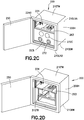
- another one of the longitudinal walls 210LNA, 210LNB and/or the lateral walls 210LTA, 210LTB may include a user access door 250 configured to allow a user access to one or more of the drive section chamber 224 and the isolated climate controlled chamber 223. Opening or removal of the door 250 may provide substantially direct user access to the drive section chamber 224.
- any suitable barrier member 224B may be connected to the frame 210F to form, for example, a removable moisture barrier between the drive section chamber 224 and the user environment.
- the barrier member 224B may be a translucent member allowing visual inspection of the drive section chamber 224 without removal of the barrier member 224B.
- Opening or removal of the door 250 may also provide access to the isolated climate controlled chamber 223.
- opening the user access door 250 may provide substantially direct access to the isolated climate controlled chamber 223.
- access to the isolated climate controlled chamber 223 may be provided through an ultra-cold temperature interface or thermal panel 2231.
- the ultra-cold temperature interface or thermal panel 2231 may be coupled to the frame 210F so as to substantially seal or otherwise isolate the isolated climate controlled chamber 223 from the user environment when the door 250 is opened or removed.
- the ultra-cold temperature interface 2231 may include one or more suitable sealable apertures 272 through which gloves may be inserted. In one aspect any suitable covers 272C may be provided for sealing the apertures 272 while in other aspects the gloves may be attached to the apertures to seal the apertures.
- any suitable seals may be provided between the respective wall 210LNA, 210LNB, 210LTA, 210LTB and one or more of the user access door 250, barrier member 224B and ultra-cold temperature interface 2231.
- the user access door 250 provides direct access to one or more of the drive section chamber 224 and isolated climate controlled chamber 223
- any suitable seals may be provided between the door 250 and walls 210LNA, 210LNB, 210LTA, 210LTB (and isolation member 263) for sealing or otherwise isolating one or more of the drive section chamber 224 and isolated climate controlled chamber 223 from each other and from an environment outside the sample selector module 200.
- the barrier member 224B may form a seal with the walls 210LNA, 210LNB, 210LTA, 210LTB (and isolation member 263) for sealing or otherwise isolating the drive section chamber 224.
- the ultra-cold temperature interface 2231 may be coupled to the frame 210F so as to substantially seal or otherwise isolate the isolated climate controlled chamber 223 from the user environment when the door 250 is open or removed.
- the seals between the respective wall 210LNA, 210LNB, 210LTA, 210LTB and one or more of the user access door 250, barrier member 224B and ultra-cold temperature interface 2231 may be magnetic seals similar to those described above with respect to tiles 261A, 261B, 261C or they may be any suitable seals provided individually or in conjunction with each other.
- the sample transfer module 200 includes one or more transfer devices 201A, 201B.
- Each transfer device 201A, 201B (described herein with respect to transfer device 201A but it should be understood that transfer device 201B may be identical to transfer device 201A) includes a respective drive portion 202A of drive section 201 and a transfer arm portion 400A.
- the drive portion 202A may be disposed within the drive section chamber 224 and include one or more rotary drive motors 401, 402, 403 connected to a frame 400F of the drive portion 202A.
- the drive portion 202A may also include at least one linear drive motor 201L2 connected to the frame 400F for moving at least a portion of the transfer arm portion 400A in the direction of arrow 299.
- the drive portion 202A may be coupled to the frame 210F of the sample selector module 200 in any suitable manner.
- the drive portion 202A may be mounted to a linear drive 201L1 of the drive section 201 that is supported within the frame 210F so that a path of travel of the linear drive 201L1 and movement of the transfer arm portion 400A carried by the linear drive 201L1 is substantially in the direction of arrow 298 (e.g. along a longitudinal axis of the sample tray 310TR or towards and away from the longitudinal walls 210LNA, 210LNB) so that the transfer arm portion travels along a respective aisle formed between the sample tray holders 300A, 300B, 300C.
- the linear drive 201L1 may be a multi-axis linear drive providing movement of the transfer arm portion 400A in the direction of arrows 297, 298.
- the linear drive 201L1 may be any suitable linear drive such as a linear stepper motor, a belt and pulley system, a screw drive or any other suitable drive.
- the drive portion 202A may ride along one or more linear rails 405A, 405B of the linear drive 201L1 while in other aspects the drive portion 202A may be supported by the linear drive 201L1 in any suitable manner.
- any suitable encoders or position detectors 406 may be provided for determining, along with controller 170, a position of the transfer arm portion 400A along a length of the linear drive 201L1 for positioning the transfer arm portion 400A relative to the sample holding locations 310 within the sample tray 310TR.
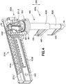
- the transfer arm portion 400A may include a coaxial (e.g. concentrically collocated) drive shaft assembly 460 having a common axis of rotation RX (which may be substantially parallel with the sample container longitudinal axis SCLA), a sample container holder 440, a top (e.g. upper) pusher member 430 and a bottom (e.g. lower) pusher member 420.
- RX which may be substantially parallel with the sample container longitudinal axis SCLA
- a sample container holder 440 which may be substantially parallel with the sample container longitudinal axis SCLA
- top e.g. upper
- a bottom e.g. lower
- the coaxial drive shaft assembly 460 and other components of the transfer arm portion 400A may be constructed of any suitable material such as, for example, a thermally non-conductive material configured to isolate the samples held by the transfer arm portion 400A from heat generated by the drive portion 201A, 202A and to isolate the drive portion from the ultra-cold temperature in which the transfer arm portion 400A operates.
- the coaxial drive shaft may be coupled to the respective drive portion 202A in any suitable manner (such as described below) and extend through the isolation member 263 into the isolated climate controlled chamber 223.
- the isolated climate controlled chamber 223 may include one or more narrow slots 263P (e.g. a value of longitudinal length of the slot is much less than a value of the lateral width of the slot) through which a respective coaxial drive shaft assembly 460 extends.
- the narrow slots 263P may be decoupled from at least one degree of freedom of a respective transfer device 201A, 201B in the array plane SCP.
- the narrow slot 263P may be sealed in any suitable manner such as with a dynamic seal 263S that moves with the coaxial drive shaft assembly 460 as the coaxial drive shaft assembly 460 travels in the direction of arrow 298 along a longitudinal length of the respective narrow slot 263P.
- the decoupling of the narrow slot 263P from the at least one degree of freedom of the respective transfer device 201A, 201B may allow for seal movement in only a single direction, such as along a travel axis in the direction of arrow 298 of a respective transfer arm portion.
- the narrow slot 263P may not be sealed where the isolation of the isolated climate controlled chamber 223 may be achieved by air currents flowing from the isolated climate controlled chamber 223 into the drive section chamber 224 due to, for example, a temperature differential between the two chambers, however the drive section chamber 224 may be maintained at a predetermined non-ultra-cold temperature in any suitable manner that accounts for cooling of the drive section chamber 224 by the passage of ultra-cold air into the drive section chamber 224.
- the narrow slots 263P (whether sealed or not sealed) may provide for increased thermal management, improved sample integrity and lower power usage by limiting or otherwise eliminating communication between the two chambers 223, 224.
- the sample container holder 440 may be coupled to an outer drive shaft 440S of the coaxial drive shaft assembly so that the sample container holder 440 and the outer drive shaft rotate as a unit about axis RX.
- the coaxial drive shaft assembly 460 may include an inner shaft having shaft portions 460S, 420S that may be formed as a single unit or coupled together in any suitable manner so as to rotate as a single unit where the inner shaft is disposed at least partly within the outer drive shaft 440S.
- the top pusher member 430 may be mounted to shaft portion 430S while the bottom pusher member 420 is mounted to shaft portion 420S so as to be located on opposite sides along the axis RX of the sample container holder 440.
- the outer drive shaft 440S may include an aperture through which the top pusher member 430 extends where the aperture may be configured to allow relative movement between the top pusher member 430 and the sample container holder 440.
- each of the outer and inner drive shafts 440S, 430S, 420S may be coupled to a common rotary drive motor 401 so that the shafts 440S, 430S, 420S and hence the sample container holder 440, top pusher member 430 and bottom pusher member 420 rotate as a unit about the axis RX.
- the inner drive shaft formed by shaft portions 430S, 420S may be linearly moveable within the outer drive shaft 440S and be coupled to the at least one linear drive 201L2 for moving the top and bottom pusher members 430, 420 as a unit in the direction of arrow 299 relative to the sample container holder 440.
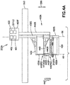
- the coupling between each of the rotary drive motor(s) 401, 402, 403 and the at least one linear drive motor 201L2 with a respective shaft of the coaxial drive shaft assembly 460 may be a substantially direct coupling (e.g. no intervening belts or chains). For example, as shown in Fig.
- each drive motor may include a drive gear DG1 (or any other suitable drive coupling) coupled to an output shaft of the drive motor that directly engages a driven gear DG2 (or any other suitable drive coupling) coupled substantially directly to a respective drive shaft without any intervening gears or other transmission members.
- the motor rotor e.g. moving portion of the motor
- any suitable transmission may be provided between the motor and respective drive shaft(s) for driving the transfer devices 201A, 201B as described herein.
- the one or more rotary drive motor 401, 402, 403, the at least one linear drive motor 201L2 and the linear drive 201L1 may constitute a mixed Polar-Cartesian coordinate system that allows transfer of sample containers between sample holding locations 310 of a single sample rack 370, 570 or between different sample racks 370, 570 located in one or more sample trays 310TR with as few as three drive motors (e.g. as described above).
- more than three motors may be used, as described below, for the transfer of sample containers between sample holding locations 310 of a single sample rack 370, 570 or between different sample racks 370, 570 located in one or more sample trays 310TR.
- polar coordinate mapping of sample holding locations 310 may allow fast coordinated motion to the sample holding locations 310 on two sample trays 310TR by each transfer device 201A, 201B.
- the drive portion 202A may be mounted to the frame 210F so as to be fixed with respect to linear movement towards and away from the side walls 210LNA, 210LNB, 210LTA, 210LTB of the sample transfer module 200 (e.g. linear drive 201L1 is not provided) so that the transfer device 201A, 201B operates substantially in a pure Polar coordinate system.
- the shaft portion 430S may form a middle drive shaft and the shaft portion 420S may form an inner drive shaft where at least the inner drive shaft is independently rotatable relative to the outer drive shaft 440S.
- the outer drive shaft 440S and the shaft portion 430S (e.g. middle drive shaft) may be coupled to a common rotary drive motor 401 so that the top pusher member 430 and the sample container holder 440 rotate as a unit about axis RX while shaft portion 420S (e.g. inner drive shaft) is coupled to a separate rotary drive motor 402 so that the bottom pusher member 420 independently rotates about axis RX.
- the shaft portion 430S e.g.
- middle drive shaft may be coupled to a separate rotary drive motor 403 so that each of the top pusher member 430, sample container holder 440 and bottom pusher member 420 are independently rotatable relative to each other.
- the shaft portion 430S and the shaft portion 420S respectively form middle and inner drive shafts
- the shaft portion 430S may be coupled to one linear drive motor of the at least one drive motor 201L2 while the shaft portion 420S may be coupled to another linear drive motor of the at least one drive motor 201L2 so that each of the top pusher member 430 and the bottom pusher member 420 are independently movable in the direction of arrow 299 relative to the sample container holder 440.
- the rotary drive motor (s) 401, 402, 403 and the at least one linear drive motor 201L2 may include any suitable encoders or position detectors for determining, along with controller 170, a position of the transfer arm portion 400A along a length of the linear drive 201L1 for positioning the transfer arm portion 400A relative to the sample holding locations 310 within the sample tray 310TR.
- the motor control adjustment of the stroke (e.g. amount of movement) of at least the top and bottom pusher members 430, 420 in the direction of arrow 299 may allow for the picking and placing of sample containers having different heights H ( Fig. 4C ).
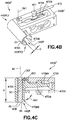
- the sample container holder 440 may include a gripper or sample container receiver 440A that is configured to hold one or more sample container types (e.g. different shapes of sample containers).
- the gripper 440A may be an interchangeable gripper that is removable from the sample container holder 440 and replaceable with a different gripper 440A' having a different predetermined characteristic than the gripper 440A.
- the different predetermined characteristics may include, for example, an ability to hold a different size/shape sample container, movable gripper actuators, a configuration for punching sample containers to/from a sample tray, a configuration for pushing sample containers to/from a sample tray, a configuration to both punch and push sample containers to/from a sample tray, etc., where the term “punch” refers to transfer of a sample tube past a bottom surface of a sample tray and “push” refers to the transfer of a sample tube past a top surface of a sample tray (for ease of explanation the terms “punch” and “push” are generally referred to herein as "push”).
- the gripper 440A may include a base member 440B that is coupled in any suitable manner to (so as to be interchangeable with other grippers) or integrally formed with the sample container holder 440.
- the base member 440B may include an aperture that passes through the base member 440B so as to form a sample container passage 440P through the base member 440B where the sample container passage 440P includes an axis AX extending through the passage and substantially along which sample containers SC are held by the gripper 440A.
- One or more biasing members 440BM such as springs or other resilient member, may be disposed at least partially within the sample container passage 440P for biasing a sample container SC ( Fig. 4C ) against a surface of the sample container passage 440P to effect a frictional engagement and retention of the sample container SC within the sample container passage 440P.
- a gripper 440A" is illustrated in accordance with an aspect of the disclosed embodiment.
- the gripper 440A" may be substantially similar to gripper 440A however, the gripper 440A" may have at least one actuable or movable gripping member or finger 470M.
- the base member 440B" may include a stationary finger 470S that forms at least part of the sample container passage 440P.
- the stationary finger 470S has a semicircular shape so as to substantially conform with a shape of the sample container SC but in other aspects the stationary finger 470S may have any suitable shape.
- the movable finger 470M may be pivotally mounted to the base member 440B" in any suitable manner so as to be pivotable about an axis of rotation RX1.
- the movable finger 470M is illustrated as having a substantially "L" shaped configuration for exemplary purposes and in other aspects the movable finger 470M may have any suitable shape.
- the movable finger 470M may include a gripping portion 470MG and an actuator portion 470MA where the gripping portion 470MG is positioned relative to the base member 440B" to be in an opposing arrangement with the stationary finger 470S so that as the movable finger 470M pivots about axis RX1 the gripping portion 470MG moves towards the stationary finger 470S for gripping the sample container SC and away from the stationary finger 470S for releasing the sample container SC.
- the movable finger 470M may be driven or otherwise actuated in any suitable manner such as with a solenoid type magnet arrangement.
- a first magnetic member 472A may be positioned on the base member 440B" and a second magnetic member 472B may be positioned on the actuator portion 470MA of the movable finger 470M in an opposing relationship with the first magnetic member 472A.
- the magnetic members 472A, 472B may be any suitable magnetic members such as, for example, neodymium magnets.
- the first magnetic member 472A may be energized in any suitable way to either attract or repel the second magnetic member to respectively release or grip the sample container SC.
- the magnetic members 472A, 472B may be positioned so that when the first magnetic member 472A is energized to either attract or repel the second magnetic member the sample container is respectively gripped or released.
- Any suitable sensor or detector 471 may be mounted to the base member 440B" and positioned relative to the movable finger 470M for detecting an open (e.g. the sample container is released) and/or closed (e.g. the sample container is gripped) position of the movable finger 470M.
- an open e.g. the sample container is released
- the sample container SC may freely fall from the gripper 440A" substantially without resistance from the gripper 440A".
- any suitable resistance may be provided by the gripper 440A" so as to control a rate of descent of the sample container SC from the gripper 440A".
- Any suitable connector 475 may be connected to one or more of the sensor 471 and first magnetic member 472A and the controller 170 so that suitable control signals may be provided by the controller and sensor signal can be received by the controller for operating the gripper 440A".
- the gripper 440A" may be a friction gripper where the magnetic members 472A, 472B are not selectively energized.
- the magnetic members 472A, 472B may be arranged so as to repel each other biasing the movable finger 470M in a closed position for gripping the sample container SC.
- the magnetic members 472A, 472B may be positioned relative to the base member 440B" and the movable finger 470M so that an attractive force between the magnetic members 472A, 472B biases the movable finger 470M in the closed position.
- the gripping portion 470MG of the movable finger 470M in the biased position may be spaced from an opposing surface of the stationary finger 470S by a distance D where the distance D is smaller than a diameter, a width or a length (e.g. depending on the shape) of the sample container SC being gripped (e.g.
- the gripping portion 470MG is disposed at least partly within the sample container passage 440P) so that as the sample container SC is inserted into the gripper 440" the gripping portion 470MG is forced away from the stationary finger 470S by the sample container SC and the biasing force of the magnetic members 472A, 472B effect a compressive/friction force between the gripping portion 470MG, the stationary finger 470S and the sample container SC for gripping the sample container SC.
- the biasing force may be provided in any suitable manner such as by springs or other suitable resilient or elastomeric member.
- a gripper 440A"' is shown in accordance with another aspect of the disclosed embodiment.
- the gripper 440A"' may be substantially similar to gripper 440A however, in this aspect the gripper 440A"' includes a moving cam member 470C that engages a sample container in a manner substantially similar to that described above with respect to the movable finger 470M.
- movement of the cam member 470C may be effected by attractive or repelling magnetic forces where the magnets are energized to cause movement of the cam member 470C in at least one of the directions 496A, 496B for opening and closing the gripper 440A"' in a manner substantially similar to that described above with respect to movable finger 470M.
- the cam member 470C may be biased in position within the sample container passage 440P such that as the sample container is moved into the sample container passage 440P the cam member is forced to move in the direction of arrow 496B by the sample container SC where a resilient or elastomeric member provides a resistive force on the cam member 470C for gripping sample container SC in a manner substantially similar to that described above.
- the cam member 470C may be coupled to the base member 440B"' in any suitable manner such as a pinned coupling so that the cam member pivots about axis RX2 in the direction of arrows 496A, 496B.
- the cam member 470C effects gripping of a sample container SC within the passage through engagement of the cam member with the sample container SC and engagement of the sample container with an interior wall of the sample container passage 440P.
- Any suitable sensors or detectors 471 may be mounted to the base member 440B"' for sensing when the gripper 440A"' is open or closed in a manner substantially similar to that described above.
- the components (e.g. base member 440B, 440B", 440B"', stationary finger 470S, gripping portion 470MG of movable finger 470M) of the gripper 440A, 440A', 440A", 440A"' forming the sample container passage 440P may include a chamfer or otherwise angled surface AS relative to an axis AX of the sample container passage 440P.
- the angled surface(s) AS may be provided at one or more ends 440PE1, 440PE2 so that at least one end 440PE1, 440PE2 of the sample container passage 440P has a lead in for insertion of the sample container SC into the sample container passage 440P.
- the angled surface(s) AS may be disposed at both ends 440PE1, 440PE2 of the sample container passage 440P.
- the end into which the sample container SC is inserted may include the angled surface (s) AS.
- the lead in formed by the angled surfaces AS may provide guidance (e.g. guiding surfaces) for directing the sample container into the gripper 440A, 440', 440A", 440A"' and account for any misalignment between the sample container SC and the sample container passage 440P.
- the gripper 441A may include a base member 441B and two movable fingers 444A, 444B coupled to the base member 441B.
- the two movable fingers 444A, 444B may form a sample container passage 440P between the fingers, however, the sample container passage may not extend through the base member 441B (e.g. the sample container passage is not a through passage and only allows insertion of the sample container SC into the gripper 441A in one direction 299A).
- the sample container passage may extend through the base member 441B to allow insertion of sample containers SC into the gripper in directions 299A, 299B.
- the gripper 441A may include any suitable actuator(s) (such as those described above) connected to the movable fingers 444A, 444B for gripping (e.g. closing the gripper) and releasing (e.g. opening the gripper) sample containers.
- the movable fingers 444A, 444B may be mounted to the base member so as to move linearly relative to the base member 441B in the direction of arrow 499 towards and away from each other to respectively grip and release a sample container SC.
- the movable fingers 444A, 444B may be mounted to the base member so as to pivot relative to a predetermined axis of rotation RX2 of the base member 441B for pivoting tips 444AT, 444BT (e.g.
- the gripper 441A may have only one movable finger (either one of fingers 444A, 444B) which may operate as described above relative to the other finger 444A, 444B (which is stationary) for gripping and releasing a sample container SC.
- the top (e.g. upper) pusher member 430 may not be provided on the at least one transfer arm portion 400A (see Fig. 4A ) such that the sample containers SC may be provided to the gripper 441A by, for example, the bottom (e.g. lower) pusher member 420 in a manner substantially similar to that described below and where the sample containers are placed into sample trays by gravity (e.g. the sample container falls freely from the gripper 441A when released for placement into a sample tray).
- the top pusher member 430 may include a sample container engagement portion 430A extending therefrom towards the gripper, such as gripper 440A for exemplary purposes only.
- the bottom pusher member 420 may also include a sample container engagement portion 420A extending therefrom towards the gripper.
- Each of the sample container engagement portions 430A, 420A may be substantially aligned with the axis AX and be configured to pass at least partially through the sample container passage 440P to effect transfer of sample containers to or from the gripper as described herein.
- sample container engagement portions 430A, 420A may have a push pin or rod configuration but in other aspects the sample container engagement portions 430A, 420A may have any suitable shape and size for at least a partial insertion into the sample container passage 440P and for engagement with the sample container SC.
- the sample selector module 200 may be configured to move sample containers SC between sample holding locations 310 within a single rack 370, 570, between multiple racks 370, 570 in a single tray 310TR and/or between multiple racks 370, 570 in multiple trays 310TR.
- the controller 170 may be configured to control automation of the sample selector module 200 (as described herein) with a required granularity for picking and placing sample containers SC to and from standard density trays 570 and high density trays 370 having any suitable spacing between sample container holding locations 310.
- standard density tray may refer to trays configured to hold an array of 24 sample containers, 48 sample containers or 96 sample containers.
- high density tray may refer to trays configured to hold an array of more than 96 sample containers.
- the high density tray 370 may have a longitudinal (e.g. lengthwise) spacing X1 between sample holding locations 310 of about 8.25 mm and a lateral (e.g. widthwise) spacing X2 between sample holding locations 310 of about 9.00 mm.
- the high density tray 370 may have a longitudinal spacing X1 between sample holding locations 310 of about 8.20 mm and a lateral spacing X2 between sample holding locations 310 of about 9.00 mm.
- the spacing X1, X2 between sample holding locations may be any suitable spacing.
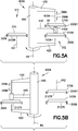
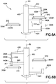
- the sample selector module 200 includes a single stack ST1 (e.g. one level) of sample tray holders 300A and a double stack ST2 (e.g. two stacked levels) of sample tray holders 300B, 300B1.
- Each stack ST1, ST2 includes a respective axis VX1, VX2 along which the respective sample tray holders 300A, 300B, 300B1 are arranged one over the other.
- the stacks ST1, ST2 may be spaced apart from one another so as to form an aisle ASL in which a respective transfer arm portion 400A travels.
- Each level in the stack may be arranged so that the level is disposed in a plane between the top pusher member 430 and the sample container holder 440 or in a plane between the sample container holder 440 and the bottom pusher member 420 so that sample containers may be pushed between the gripper of the sample container holder and a respective level of tray holders.
- the sample tray holder 300A is holding a sample tray 310TR having one or more high density racks 370 thereon and the sample tray holders 300B, 300B1 are each holding a sample tray 310TR having one or more standard density racks 570A, 570B thereon.
- the rack 570A may be a source rack (e.g. a rack from which sample containers SC are removed or picked) and racks 370, 570B may be destination racks (e.g. racks to which sample containers are placed).
- top pusher member 430 and bottom pusher member 420 are arranged to move in the direction of arrows 299A, 299B as a unit relative to the sample container holder 440 (as described above). Also in this aspect the top pusher member 430, bottom pusher member 420 and the sample container holder 440 are arranged to rotate as a unit about axis RX (as described above) .
- gripper 440A is illustrated in other aspects the gripper may be any one of the grippers 440A, 440A', 440", 440A"', 441A described herein (noting that the gripper 441A may only receive sample containers delivered to the gripper in the direction of arrow 299A in the aspect where the passage 440P in the gripper 441A is not a through passage).
- sample containers SC may be transferred between trays 570A, 570B stacked one above the other.
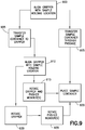
- the axis AX of the gripper may be positioned over a predetermined sample container holder location 310 of the source tray in any suitable manner ( Fig. 9 , Block 900).
- the transfer arm portion 400A may be linearly moved in the direction of arrow 298 and/or rotated about axis RX for substantially aligning the axis AX with the predetermined sample container holder location 310 of the source tray 570A which in this example is disposed on a level between the top pusher member 430 and the sample container holder 440.
- the top and bottom pusher members 430, 420 may be actuated to move in the direction of arrow 299B to push a sample container from the predetermined sample holder location into the gripper 440A ( Fig. 9 , Block 905).
- the top and bottom pusher members 430, 420 may be actuated to move in the direction of arrow 299A to push a sample container into the gripper 440A from the predetermined sample holder location of the source tray.
- the sample container SC may be transported by the transfer arm portion 400A to substantially align the axis AX of the gripper 440A with a predetermined sample container holding location 310 of a destination tray 570B, 370 ( Fig. 9 , Block 910.
- the alignment of the gripper 440A with the predetermined sample container holding location 310 of a destination tray 570B, 370 may include moving the transfer arm portion linearly in the direction of arrow 298 and/or rotating the top pusher member 430, bottom pusher member 420 and the sample container holder 440 as a unit about axis RX ( Fig. 9 , Block 915).
- the top and bottom pusher members 430, 420 may be actuated to move in the direction of arrow 299B to push a sample container from the gripper 440A into the predetermined sample holder location of the destination tray 370, 570B ( Fig. 9 , Block 920).
- the destination tray (which may be on the same level as the source tray or where the source tray is also the destination tray) is disposed on a level between the top pusher member 430 and the sample container holder 440 the top and bottom pusher members 430, 420 may be actuated to move in the direction of arrow 299A to push a sample container from the gripper 440A into the predetermined sample holder location of the destination tray.
- the top and bottom pusher members 430, 420 may be actuated so that one of the sample container engagement portions 430A, 430B pushes the sample container from the predetermined sample container holding location 310 of the source tray through the sample container passage 440P ( Fig. 9 , Block 925) and into the predetermined sample container holding location 310 of the destination tray ( Fig. 9 , Block 920).
- the sample container passage 440P of the gripper guides the transfer of the sample container SC between the source and destination sample container holding locations 310.
- the pass through transfer of sample containers may be performed regardless of whether one or more of the top pusher member 430, the bottom pusher member 420 and the sample container holder 440 are independently rotatable.
- a transfer of a sample container between a source tray 570 disposed on a level between the top pusher member 430 and the sample container holder 440 and a destination tray 370 disposed on a level between the sample container holder 440 and the bottom pusher member 420 will be described.
- at least the bottom pusher member 420 may be independently rotatable about axis RX relative to the sample container gripper 440.
- the axis AX of the gripper may be positioned over a predetermined sample container holder location 310 of the source tray in any suitable manner ( Fig. 9 , Block 900).
- the transfer arm portion 400A may be linearly moved in the direction of arrow 298 and/or the bottom pusher member 420, the top pusher member 430 and the sample container holder 440 (e.g. rotation of the bottom pusher member 420 is controlled independently from rotation of the upper pusher member 430 and sample container holder 440) are rotated about axis RX for substantially aligning the axis AX with the predetermined sample container holder location 310 of the source tray 570 which in this example is disposed on a level between the top pusher member 430 and the sample container holder 440.
- the top pusher member 430 may be actuated to move in the direction of arrow 299B to push a sample container from the predetermined sample holder location into the gripper 440A ( Fig. 9 , Block 905).
- the top and bottom pusher members 430, 420 may move in the direction of arrows 299A, 229B as a unit while in other aspects the top and bottom pusher members 430, 420 may be independently movable in the directions of arrows 299A, 299B.
- the bottom pusher member 420 may be actuated to move in the direction of arrow 299A to push a sample container into the gripper 440A from the predetermined sample holder location of the source tray.
- the sample container SC may be transported by the transfer arm portion 400A to substantially align the axis AX of the gripper 440A with a predetermined sample container holding location 310 of a destination tray 570B, 370 ( Fig. 9 , Block 910).
- the alignment of the gripper 440A with the predetermined sample container holding location 310 of a destination tray 370 may include moving the transfer arm portion 400A linearly in the direction of arrow 298 and/or rotating the sample container holder 440 and the top pusher member 430 as a unit about axis RX ( Fig. 9 , Block 915).
- the bottom pusher member 420 may also be rotated, albeit independently from the unitary rotation of the top pusher member 430 and the sample container holder 440.
- the top pusher member 430 may be actuated to move in the direction of arrow 299B to push a sample container from the gripper 440A into the predetermined sample holder location of the destination tray 370 ( Fig. 9 , Block 920).
- the bottom pusher member 420 may be actuated to move in the direction of arrow 299A to push a sample container from the gripper 440A into the predetermined sample holder location of the destination tray.
- both the top pusher member 430 and the bottom pusher member 420 may be independently rotatable about axis RX relative to the sample container gripper 440.
- the axis AX of the gripper may be positioned over a predetermined sample container holder location 310 of the source tray in any suitable manner ( Fig. 9 , Block 900).
- the transfer arm portion 400A may be linearly moved in the direction of arrow 298 and/or the sample container holder 440 may be rotated about axis RX for substantially aligning the axis AX with the predetermined sample container holder location 310 of the source tray 370.
- One or more of the top pusher member 430 and the bottom pusher member 420 may be independently rotated so that the respective sample container engagement portion 430A, 420A is substantially aligned with the axis AX and the predetermined sample holding location 310 of the source tray 370.
- the source tray 370 is disposed on a level between the bottom pusher member 420 and the sample container holder 440 so the bottom pusher member 420 is independently rotated about axis RX to remove the sample container SC from the source tray 370.
- at least the bottom pusher member 420 may be actuated to move in the direction of arrow 299A to push a sample container SC from the predetermined sample holder location into the gripper 440A ( Fig. 9 , Block 905).
- top and bottom pusher members 430, 420 may move in the direction of arrows 299A, 229B as a unit while in other aspects the top and bottom pusher members 430, 420 may be independently movable in the directions of arrows 299A, 299B. It is noted that where the source tray is on a level disposed between the top pusher member 430 and the sample container holder 440 at least the top pusher member 430 may rotated and actuated to move in the direction of arrow 299B to push a sample container into the gripper 440A from the predetermined sample holder location of the source tray.
- the sample container SC may be transported by the transfer arm portion 400A to substantially align the axis AX of the gripper 440A with a predetermined sample container holding location 310 of a destination tray 570B, 370 ( Fig. 9 , Block 910).
- the alignment of the gripper 440A with the predetermined sample container holding location 310 of the destination tray 570 may include moving the transfer arm portion 400A linearly in the direction of arrow 298 and/or rotating the sample container holder 440 about axis RX ( Fig. 9 , Block 930).
- top pusher member 430 and the bottom pusher member 420 may also be independently rotated so that the respective sample container engagement portion 430A, 420A is substantially aligned with the axis AX and the predetermined sample holding location 310 of the destination tray 570 ( Fig. 9 , Block 935).
- at least the top pusher member 430 may be actuated to move in the direction of arrow 299B to push a sample container from the gripper 440A into the predetermined sample holder location of the destination tray 570 ( Fig. 9 , Block 920).
- the bottom pusher member 420 may be actuated to move in the direction of arrow 299A to push a sample container from the gripper 440A into the predetermined sample holder location of the destination tray.
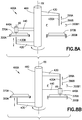
- sample container transfer involves sample container transport between high density trays 370 and standard density trays 570 and between multiple standard density trays.
- sample container transfer may also be provided between multiple high density trays 370A, 370B in a manner substantially described above with respect to Figs. 5A-7B .
- the example illustrated in Figs. 8A and 8B is similar to that illustrated in Figs. 7A and 7B where the top and bottom pusher members 430, 420 are each independently rotatable relative to the sample container holder 440 such that sample container transfer is performed in a manner substantially similar to that described above with respect to Figs. 7A and 7B .
- bottom pusher member 420 and top pusher member 730 may be independently movable in the direction of arrows 299A, 299B relative to the other one of top pusher member 430 and bottom pusher member 420 as well as the sample container holder 440 to prevent unwanted insertion of a respective sample container engagement portion 430A, 420A into an occupied sample container holding location 310.
- the upper pusher arm 430 and the lower pusher arm 420 could be used to clamp a sample container SC between them for transfer of the sample container SC to and from the gripper 440A.
- the rack such as rack 570 shown in Figs. 10A and 10B or any other suitable rack such as rack 370
- the upper pusher arm 430 may be moved in the direction of arrow 299B towards a top surface of the sample container SC such that the sample container engagement portion 430A extends through the gripper 440A to substantially contact the top surface of the sample container SC.
- the lower pusher arm 420 may be moved in the direction of arrow 299A towards the sample container so that the sample container engagement portion 420A substantially contacts a bottom surface of the sample container SC such that the sample container is clamped between the sample container engagement portions 430A, 420A.
- the lower pusher arm 420 may be moved in the direction of arrow 299A towards a bottom surface of the sample container SC such that the sample container engagement portion 420A extends through the gripper 440A to substantially contact the bottom surface of the sample container SC.
- the upper pusher arm 430 may be moved in the direction of arrow 299B towards the sample container so that the sample container engagement portion 430A substantially contacts the bottom surface of the sample container SC such that the sample container is clamped between the sample container engagement portions 430A, 420A.
- the sample container SC can be moved to the gripper 440A via simultaneous movement of the upper and lower pusher arms 420, 430 in one of the directions 299A, 299B depending on, for example, a location of the tray 570 relative to the gripper. Transfer of the sample container SC in this manner may provide higher alignment reliability by holding the sample container SC to its longitudinal axis. Also referring to Fig. 10C , the ends 1000A, 1000B of the sample container engagement portions 430A, 420A could be adapted to cradle the ends of the sample container and/or, referring to Fig.
- the sample container could have features 1001A, 1001B configured to register with the ends 1000A, 1000B of the sample container engagement portions 430A, 420A.
- the upper and lower pusher arms 430, 420 may clamp the sample container SC during rotation about axis RX such that one of the upper and lower pusher arms 430, 420 is moved in the direction of arrow 299A, 299B to clear the tray 570 and then move in the direction of arrow 299A, 299B to re-engage the sample container SC during rotation about axis RX.
Landscapes
- Chemical & Material Sciences (AREA)
- General Health & Medical Sciences (AREA)
- General Physics & Mathematics (AREA)
- Life Sciences & Earth Sciences (AREA)
- Immunology (AREA)
- Analytical Chemistry (AREA)
- Biochemistry (AREA)
- Pathology (AREA)
- Health & Medical Sciences (AREA)
- Physics & Mathematics (AREA)
- Engineering & Computer Science (AREA)
- Robotics (AREA)
- Chemical Kinetics & Catalysis (AREA)
- Mechanical Engineering (AREA)
- Automatic Analysis And Handling Materials Therefor (AREA)
- Warehouses Or Storage Devices (AREA)
- Manipulator (AREA)
- Specific Conveyance Elements (AREA)
Claims (15)
- Einrichtung (200), umfassend:einen Rahmen (210F), der konfiguriert ist, um Probenbehälter (SC) in einer Anordnung von Probenhalterpositionen (310) zu halten, wobei jeder Probenbehälter (SC) in der zweidimensionalen Anordnung mit einer Längsachse (SCLA) des Probenbehälters (SC) angeordnet ist, der sich von der Anordnungsebene nach außen erstreckt;einen Antriebsabschnitt (201), der mit dem Rahmen (210F) verbunden ist; dadurch gekennzeichnet, dass die Einrichtung umfasst:mindestens einen Transferarm (400A), der drehbar mit dem Antriebsabschnitt (201) verbunden ist, so dass sich jeder Transferarm (400A) um eine jeweilige Drehachse (RX) dreht, die im Wesentlichen parallel zur Längsachse (SCLA) des Probenbehälters (SC) ausgerichtet ist, wobei jeder Transferarm (400A) einen Probenbehältergreifer (440A, 440A', 440A", 440A"') umfasst, der konfiguriert ist, um einen Probenbehälter (SC) zu greifen;mindestens ein Schubelement (420, 430), das beweglich mit dem Antriebsabschnitt (201) verbunden ist, wobei sich das mindestens eine Schubelement (420, 430) von dem Probenbehältergreifer (440A, 440A', 440A", 440A"') unterscheidet und für eine lineare Bewegung entlang der Längsachse (SCLA) des Probenbehälters (SC) in Bezug auf einen jeweiligen Transferarm (400A) undProbenbehältergreifer (440A, 440A', 440A", 440A"') konfiguriert ist, wobei das mindestens eine Schubelement (420, 430) so konfiguriert ist, dass der Eingriff mit mindestens einer unteren oder oberen Oberfläche des Probenbehälters (SC) eine Längsübersetzung des Probenbehälters (SC) bewirkt, um den Probenbehälter (SC) durch den jeweiligen Transferarm (400A) in einer Längsrichtung (299) entlang der Längsachse (SCLA) zu erfassen und freizugeben; undein Isolationselement (263), das den Rahmen (210F) in isolierte Umgebungen teilt, so dass der Antriebsabschnitt (201) in einer Antriebsabschnittskammer (224) von einer Umgebung einer Ultratieftemperaturkammer (223) isoliert ist, in welcher der mindestens eine Transferarm (400A) und ein jeweiliger Probenbehältergreifer (440A, 440A', 440A", 440A"') arbeiten.
- Einrichtung (200) nach Anspruch 1, wobei der Probenbehältergreifer (440A, 440A', 440A", 440A"') konfiguriert ist, um den Probenbehälter (SC) durch einen Reibungsgriff in Eingriff zu bringen und zu greifen, oder ein Klemmelement einschließt, das konfiguriert ist, um den Probenbehälter (SC) durch eine Klemmbetätigung aktiv in Eingriff zu bringen und zu greifen.
- Einrichtung (200) nach Anspruch 1, wobei das mindestens eine Schubelement (420, 430) ein weiteres Schubelement (420, 430) umfasst, das beweglich mit dem Antriebsabschnitt (201) verbunden ist, wobei sich das andere Schubelement (420, 430) von dem Probenbehältergreifer unterscheidet und für eine lineare Bewegung entlang der Längsachse (SCLA) des Probenbehälters (SC) in Bezug auf den jeweiligen Transferarm (400A) und Probenbehältergreifer (440A, 440A', 440A", 440A"') konfiguriert ist, wobei das andere Schubelement (420, 430) so konfiguriert ist, dass der Eingriff mit mindestens einer unteren oder oberen Oberfläche des Probenbehälters (SC) eine Längsübersetzung des Probenbehälters (SC) bewirkt, um den Probenbehälter (SC) durch den jeweiligen Transferarm (400A) in der Längsrichtung (299) zu erfassen und freizugeben.
- Einrichtung (200) nach Anspruch 3,wobei der jeweilige Transferarm (400A) und das andere Schubelement (420, 430) so angeordnet sind, dass sie sich auf gegenüberliegenden Seiten einer Probenschale (310TR) befinden, die innerhalb der Einrichtung (200) angeordnet ist, wobei die Probenschale (310TR) konfiguriert ist, um mindestens einen Probenbehälter (SC) zu halten,oder der jeweilige Transferarm (400A) und das andere Schubelement (420, 430) so angeordnet sind, dass sie sich auf einer gemeinsamen Seite einer Probenschale (310TR) befinden, die innerhalb der Einrichtung (200) angeordnet ist, wobei die Probenschale (310TR) konfiguriert ist, um mindestens einen Probenbehälter (SC) zu halten, oder der Probenbehältergreifer (440A, 440A', 440A", 440A''') des jeweiligen Transferarms (400A), und das mindestens eine Schubelement (420, 430) so angeordnet sind, dass sie sich auf gegenüberliegenden Seiten einer Probenschale (310TR) befinden, die innerhalb der Einrichtung (200) angeordnet ist, wobei die Probenschale (310TR) konfiguriert ist, um mindestens einen Probenbehälter (SC) zu halten, oderder Probenbehältergreifer (440A, 440A', 440A", 440A''') des jeweiligen Transferarms (400A) und das mindestens eine Schubelement (420, 430) so angeordnet sind, dass sie sich auf einer gemeinsamen Seite einer Probenschale (310TR) befinden, die innerhalb der Einrichtung (200) angeordnet ist, wobei die Probenschale (310TR) konfiguriert ist, um mindestens einen Probenbehälter (SC) zu halten.
- Einrichtung (200) nach einem der Ansprüche 1 und 4, wobei:eines oder mehrere des mindestens einen Schubelements (420, 430) und des anderen Schubelements (420, 430) unabhängig um die jeweilige Drehachse (RX) in Bezug auf mindestens einen aus dem jeweiligen Transferarme (400A), dem Probenbehältergreifer (440A, 440A', 440A", 440A''') und zueinander drehbar sind, odereines oder mehrere des mindestens einen Schubelements (420, 430) und des anderen Schubelements (420, 430) mit dem jeweiligen Transferarm (400A) als Einheit um die jeweilige Drehachse (RX) drehen oderdas mindestens eine Schubelement (420, 430) unabhängig um die jeweilige Drehachse (RX) in Bezug auf den jeweiligen Transferarm (400A) und Probenbehältergreifer (440A, 440A', 440A", 440A''') drehbar ist, oderdas mindestens eine Schubelement (420, 430) mit dem jeweiligen Transferarm (400A) als eine Einheit um die jeweilige Drehachse (RX) dreht.
- Einrichtung (200) nach Anspruch 1, wobei das Isolationselement (263) mindestens eine abgedichtete Durchdringung einschließt, durch die sich der mindestens eine Transferarm (400A) erstreckt, und sich der mindestens eine Übertragungsarm (400A) linear in der Anordnungsebene entlang einer linearen Bewegungsachse (298) bewegt und die abgedichtete Durchdringung konfiguriert ist, um sich mit dem mindestens einen Transferarm (400A) entlang der linearen Bewegungsachse (298) zu bewegen.
- Einrichtung (200) nach Anspruch 1, ferner umfassend mindestens einen Probenschalenhalter (300A, 300B, 300C), der so konfiguriert ist, dass eine oder mehrere Probenschalen (310TR) in einen jeweiligen Probenschalenhaltebereich geschoben werden, wobei der mindestens eine Transferarm (400A) so konfiguriert ist, dass er Probenbehälter (SC) zwischen Probenhalterpositionen (310) der einen oder mehreren Probenschalen (310TR) bewegt.
- Einrichtung (200) nach Anspruch 1, wobei der mindestens eine Transferarm (400A) zwei Transferarme (400) umfasst, die an gegenüberliegenden Seiten eines Probenschalenhaltebereichs innerhalb des Rahmens (210F) angeordnet sind.
- Einrichtung (200) nach Anspruch 1, wobei der Rahmen (210F) eine Kammer definiert, die mindestens teilweise innerhalb eines Kühllagers (200) angeordnet ist.
- Einrichtung (200) nach Anspruch 9, wobei der Rahmen (210F) konfiguriert ist, um mit einer verschließbaren Öffnung in einer Wand des Kühllagers (100) zusammenzupassen.
- Einrichtung (200) nach Anspruch 9, wobei der Rahmen (210F) mindestens eine verschließbare Öffnung (260A, 260B, 260C) innerhalb des Kühllagers (100) definiert, durch die Probenbehälter (SC) in den Rahmen (210F) eingesetzt und daraus entfernt werden, und einen Schiebeverschluss (261A, 261B, 261C) einschließt, der magnetisch an der Kammer abgedichtet ist, um eine jeweilige verschließbare Öffnung (260A, 260B, 260C) abzudichten.
- Einrichtung (200) nach Anspruch 11, wobei der Rahmen (210F) ferner eine verschließbare Zugangsöffnung (250) definiert, die sich von der mindestens einen verschließbaren Öffnung (260A, 260B, 260C) unterscheidet und so konfiguriert ist, dass sie Zugang zu einem Inneren des Rahmens (210F) bereitstellt, und die verschließbare Zugangsöffnung (250) außerhalb des Kühlhauses (100) angeordnet ist.
- Einrichtung (200) nach Anspruch 9, wobei die Kammer eine tragbare Kammer ist, die an einem Transfer-Shuttle (112) des Kühllagers (100) angeordnet ist.
- Einrichtung (200) nach Anspruch 1, wobei der Probenbehältergreifer (440A, 440A') ein austauschbarer Greifer ist, der konfiguriert ist, um von dem mindestens einen Transferarm (400A) entfernt und daran befestigt zu werden.
- Verfahren zum Überführen von Probenbehältern (SC) in eine Kühllagerumgebung, wobei die Probenbehälter (SC) innerhalb eines Rahmens (210F) in einer Anordnung von Probenbehälterpositionen (310) gehalten werden und in der zweidimensionalen Anordnung mit einer Längsachse (SCLA) jedes der Probenbehälter (SC), die sich von der Anordnungsebene nach außen erstreckt, angeordnet sind, wobei das Verfahren dadurch gekennzeichnet ist, dass das Verfahren umfasst:Ausrichten eines Probenbehältergreifers (440A, 440A', 440A", 440A''') und mindestens eines Schubelements (420, 430) mit einem vorbestimmten Probenbehälter (SC) in der Anordnung durch mindestens Drehen, mit einem Antriebsabschnitt (201), des Probenbehältergreifers (440A, 440A', 440A", 440A''') und des mindestens einen Schubelements (420, 430) um eine gemeinsame Drehachse (RX), die im Wesentlichen parallel zur Längsachse (SCLA) ist, wobei sich das mindestens eine Schubelement (420, 430) von dem Probenbehältergreifer (440A, 440A', 440A", 440A''') unterscheidet; undÜberführen des vorbestimmten Probenbehälters (SC) zwischen der Anordnung und dem Probenbehältergreifer (440A, 440A', 440A'', 440A'''), zum einen oder mehreren Erfassen und Freigeben des Probenbehälters (SC) durch den Probenbehältergreifer (440A, 440A', 440A", 440A''') in einer Längsrichtung (299) entlang der Längsachse (SCLA) durch lineares Bewegen des mindestens einen Schubelements (420, 430) in Bezug auf den Probenbehältergreifer (440A, 440A', 440A", 440A''') in Längsrichtung (299) zum Ineingriffbringen mit mindestens einer unteren oder oberen Oberfläche des Probenbehälters (SC) und Bewirken einer Längsübersetzung des Probenbehälters (SC), wobei ein Isolationselement (263) den Rahmen (210F) in isolierte Umgebungen teilt, so dass der Antriebsabschnitt (201) in einer Antriebsabschnittskammer (224) von einer Umgebung einer Ultratieftemperaturkammer (223) isoliert ist, in welcher der Probenbehältergreifer (440A, 440A', 440A'', 440A''') und das mindestens eine Schubelement (420, 430) arbeiten.
Priority Applications (1)
| Application Number | Priority Date | Filing Date | Title |
|---|---|---|---|
| EP21193931.9A EP3951400B1 (de) | 2014-03-28 | 2015-03-06 | Probenwähler |
Applications Claiming Priority (2)
| Application Number | Priority Date | Filing Date | Title |
|---|---|---|---|
| US14/229,077 US9630775B2 (en) | 2014-03-28 | 2014-03-28 | Sample selector |
| PCT/US2015/019126 WO2015148091A1 (en) | 2014-03-28 | 2015-03-06 | Sample selector |
Related Child Applications (2)
| Application Number | Title | Priority Date | Filing Date |
|---|---|---|---|
| EP21193931.9A Division EP3951400B1 (de) | 2014-03-28 | 2015-03-06 | Probenwähler |
| EP21193931.9A Division-Into EP3951400B1 (de) | 2014-03-28 | 2015-03-06 | Probenwähler |
Publications (2)
| Publication Number | Publication Date |
|---|---|
| EP3123177A1 EP3123177A1 (de) | 2017-02-01 |
| EP3123177B1 true EP3123177B1 (de) | 2021-10-06 |
Family
ID=52774547
Family Applications (2)
| Application Number | Title | Priority Date | Filing Date |
|---|---|---|---|
| EP21193931.9A Active EP3951400B1 (de) | 2014-03-28 | 2015-03-06 | Probenwähler |
| EP15713058.4A Active EP3123177B1 (de) | 2014-03-28 | 2015-03-06 | Probenwähler |
Family Applications Before (1)
| Application Number | Title | Priority Date | Filing Date |
|---|---|---|---|
| EP21193931.9A Active EP3951400B1 (de) | 2014-03-28 | 2015-03-06 | Probenwähler |
Country Status (5)
| Country | Link |
|---|---|
| US (2) | US9630775B2 (de) |
| EP (2) | EP3951400B1 (de) |
| JP (1) | JP6680689B2 (de) |
| DK (1) | DK3123177T3 (de) |
| WO (1) | WO2015148091A1 (de) |
Families Citing this family (11)
| Publication number | Priority date | Publication date | Assignee | Title |
|---|---|---|---|---|
| US11054346B2 (en) | 2013-04-11 | 2021-07-06 | Rarecyte, Inc. | Detecting a substrate |
| US10072927B2 (en) * | 2016-01-07 | 2018-09-11 | Rarecyte, Inc. | Detecting a substrate |
| EP3032265B1 (de) * | 2014-12-13 | 2021-09-08 | F. Hoffmann-La Roche AG | Vorrichtung zur Aufbewahrung von Fluidbehältern |
| WO2016210420A1 (en) | 2015-06-26 | 2016-12-29 | Abbott Laboratories | Reaction vessel exchanger device for a diagnostic analyzer |
| EP3165917A1 (de) * | 2015-11-03 | 2017-05-10 | C. Gerhardt GmbH & Co. KG | Verfahren für die analyse von in einem reagenzglas enthaltenen inhaltsstoffen und zur durchführung des verfahrens geeignete vorrichtung |
| EP3901634A1 (de) * | 2016-01-20 | 2021-10-27 | Brooks Automation, Inc. | Mikroplatte mit suboptimaler einlagerungsdichte umfassend probenröhrchenhalter, und verfahren |
| DE102016111042A1 (de) | 2016-06-16 | 2017-12-21 | Hamilton Storage Gmbh | Greifvorrichtung |
| DE102016116498A1 (de) * | 2016-09-02 | 2018-03-08 | Hamilton Storage Gmbh | Verfahren zum Aufnehmen eines Probengefäßes aus einem Probenträger und zur Durchführung des Verfahrens ausgebildete Vorrichtung |
| JP7321182B2 (ja) * | 2018-03-23 | 2023-08-04 | アゼンタ・インコーポレーテッド | 自動化極低温貯蔵及び回収システム |
| CN108706259B (zh) * | 2018-03-26 | 2020-10-02 | 孟祥英 | 一种用于医学检验科的样品存储及管理系统及方法 |
| CN109856296B (zh) * | 2019-02-25 | 2021-01-15 | 浙江省食品药品检验研究院 | 一种可自行选择检测样本的气相色谱仪 |
Citations (2)
| Publication number | Priority date | Publication date | Assignee | Title |
|---|---|---|---|---|
| EP1477813A1 (de) * | 2003-05-13 | 2004-11-17 | The Automation Partnership (Cambridge) Limited | Übertragungsgerät für Fläschen |
| US20100028214A1 (en) * | 2008-07-31 | 2010-02-04 | Hamilton Storage Technologies, Inc. | Tube picking mechanism for an automated, ultra-low temperature storage and retrieval system |
Family Cites Families (5)
| Publication number | Priority date | Publication date | Assignee | Title |
|---|---|---|---|---|
| US8252232B2 (en) | 2006-01-23 | 2012-08-28 | Brooks Automation, Inc. | Automated system for storing, retrieving and managing sample |
| US8703492B2 (en) * | 2007-04-06 | 2014-04-22 | Qiagen Gaithersburg, Inc. | Open platform hybrid manual-automated sample processing system |
| WO2011066269A1 (en) * | 2009-11-24 | 2011-06-03 | Siemens Healthcare Diagnostics Inc. | Automated, refrigerated specimen inventory management system |
| US9163869B2 (en) | 2010-09-09 | 2015-10-20 | Hamilton Storage Technologies, Inc. | Tube picking mechanisms with an ultra-low temperature or cryogenic picking compartment |
| EP2776848B1 (de) * | 2011-11-07 | 2019-12-25 | Beckman Coulter, Inc. | System und verfahren zum transport von probenbehältern |
-
2014
- 2014-03-28 US US14/229,077 patent/US9630775B2/en active Active
-
2015
- 2015-03-06 JP JP2016559618A patent/JP6680689B2/ja active Active
- 2015-03-06 EP EP21193931.9A patent/EP3951400B1/de active Active
- 2015-03-06 WO PCT/US2015/019126 patent/WO2015148091A1/en active Application Filing
- 2015-03-06 DK DK15713058.4T patent/DK3123177T3/da active
- 2015-03-06 EP EP15713058.4A patent/EP3123177B1/de active Active
-
2017
- 2017-04-25 US US15/496,989 patent/US10101352B2/en active Active
Patent Citations (2)
| Publication number | Priority date | Publication date | Assignee | Title |
|---|---|---|---|---|
| EP1477813A1 (de) * | 2003-05-13 | 2004-11-17 | The Automation Partnership (Cambridge) Limited | Übertragungsgerät für Fläschen |
| US20100028214A1 (en) * | 2008-07-31 | 2010-02-04 | Hamilton Storage Technologies, Inc. | Tube picking mechanism for an automated, ultra-low temperature storage and retrieval system |
Also Published As
| Publication number | Publication date |
|---|---|
| EP3951400A1 (de) | 2022-02-09 |
| JP2017512732A (ja) | 2017-05-25 |
| WO2015148091A1 (en) | 2015-10-01 |
| EP3123177A1 (de) | 2017-02-01 |
| US10101352B2 (en) | 2018-10-16 |
| JP6680689B2 (ja) | 2020-04-15 |
| US20170227561A1 (en) | 2017-08-10 |
| US20150274423A1 (en) | 2015-10-01 |
| EP3951400B1 (de) | 2024-05-22 |
| DK3123177T3 (da) | 2021-12-20 |
| US9630775B2 (en) | 2017-04-25 |
Similar Documents
| Publication | Publication Date | Title |
|---|---|---|
| EP3123177B1 (de) | Probenwähler | |
| CN101970115B (zh) | 用于储藏、取回和管理样品的自动化系统 | |
| US10175259B2 (en) | Laboratory cargo distribution system, laboratory automation system and method of operating a laboratory cargo distribution system | |
| JP6931036B2 (ja) | 試料容器運搬装置、検査室試料分配システム、および検査室自動化システム | |
| US8857208B2 (en) | Automated substance storage | |
| JP2023156373A (ja) | 消費媒体補充ステーション | |
| US11988681B2 (en) | Automated sample storage system having storage consumable with sub-optimal storage density | |
| EP3006867B1 (de) | Kühllagerungsvorrichtung mit rotierender verschlusskammer | |
| US10604356B2 (en) | Article conveying device | |
| JP2017512732A5 (de) | ||
| CN116171981A (zh) | 便携式低温工作站 | |
| CN114279128A (zh) | 一种结核分枝杆菌耐药性实验用的样品智能冷藏箱 | |
| EP3860761A1 (de) | Rohraufnahmemechanismus mit universalem aufnahmekopf und cache | |
| WO2013013246A1 (en) | Method and device for compensation for dimensional variations in low temperature sample group holders | |
| US5271702A (en) | Robotic substrate manipulator | |
| US20220050122A1 (en) | Plate changer for auto-sampler | |
| KR20200050131A (ko) | 콜릿 교체 장치 | |
| CN217436865U (zh) | 用于释放或锁住工作台的结构和转运分离装置 | |
| CN116040094A (zh) | 样本存储装置 | |
| EP2734848B1 (de) | Verfahren und vorrichtung zur kompensation der grössenvariationen bei niedrigtemperatur-probengruppenhaltern |
Legal Events
| Date | Code | Title | Description |
|---|---|---|---|
| STAA | Information on the status of an ep patent application or granted ep patent |
Free format text: STATUS: THE INTERNATIONAL PUBLICATION HAS BEEN MADE |
|
| PUAI | Public reference made under article 153(3) epc to a published international application that has entered the european phase |
Free format text: ORIGINAL CODE: 0009012 |
|
| STAA | Information on the status of an ep patent application or granted ep patent |
Free format text: STATUS: REQUEST FOR EXAMINATION WAS MADE |
|
| 17P | Request for examination filed |
Effective date: 20161026 |
|
| AK | Designated contracting states |
Kind code of ref document: A1 Designated state(s): AL AT BE BG CH CY CZ DE DK EE ES FI FR GB GR HR HU IE IS IT LI LT LU LV MC MK MT NL NO PL PT RO RS SE SI SK SM TR |
|
| AX | Request for extension of the european patent |
Extension state: BA ME |
|
| DAV | Request for validation of the european patent (deleted) | ||
| DAX | Request for extension of the european patent (deleted) | ||
| STAA | Information on the status of an ep patent application or granted ep patent |
Free format text: STATUS: EXAMINATION IS IN PROGRESS |
|
| 17Q | First examination report despatched |
Effective date: 20200318 |
|
| STAA | Information on the status of an ep patent application or granted ep patent |
Free format text: STATUS: EXAMINATION IS IN PROGRESS |
|
| GRAP | Despatch of communication of intention to grant a patent |
Free format text: ORIGINAL CODE: EPIDOSNIGR1 |
|
| STAA | Information on the status of an ep patent application or granted ep patent |
Free format text: STATUS: GRANT OF PATENT IS INTENDED |
|
| INTG | Intention to grant announced |
Effective date: 20210428 |
|
| GRAS | Grant fee paid |
Free format text: ORIGINAL CODE: EPIDOSNIGR3 |
|
| GRAA | (expected) grant |
Free format text: ORIGINAL CODE: 0009210 |
|
| STAA | Information on the status of an ep patent application or granted ep patent |
Free format text: STATUS: THE PATENT HAS BEEN GRANTED |
|
| AK | Designated contracting states |
Kind code of ref document: B1 Designated state(s): AL AT BE BG CH CY CZ DE DK EE ES FI FR GB GR HR HU IE IS IT LI LT LU LV MC MK MT NL NO PL PT RO RS SE SI SK SM TR |
|
| REG | Reference to a national code |
Ref country code: GB Ref legal event code: FG4D |
|
| REG | Reference to a national code |
Ref country code: CH Ref legal event code: EP Ref country code: AT Ref legal event code: REF Ref document number: 1436648 Country of ref document: AT Kind code of ref document: T Effective date: 20211015 |
|
| REG | Reference to a national code |
Ref country code: IE Ref legal event code: FG4D |
|
| REG | Reference to a national code |
Ref country code: DE Ref legal event code: R096 Ref document number: 602015073875 Country of ref document: DE |
|
| REG | Reference to a national code |
Ref country code: DK Ref legal event code: T3 Effective date: 20211216 |
|
| REG | Reference to a national code |
Ref country code: SE Ref legal event code: TRGR |
|
| REG | Reference to a national code |
Ref country code: NL Ref legal event code: FP |
|
| REG | Reference to a national code |
Ref country code: LT Ref legal event code: MG9D |
|
| REG | Reference to a national code |
Ref country code: NO Ref legal event code: T2 Effective date: 20211006 |
|
| REG | Reference to a national code |
Ref country code: AT Ref legal event code: MK05 Ref document number: 1436648 Country of ref document: AT Kind code of ref document: T Effective date: 20211006 |
|
| PG25 | Lapsed in a contracting state [announced via postgrant information from national office to epo] |
Ref country code: RS Free format text: LAPSE BECAUSE OF FAILURE TO SUBMIT A TRANSLATION OF THE DESCRIPTION OR TO PAY THE FEE WITHIN THE PRESCRIBED TIME-LIMIT Effective date: 20211006 Ref country code: LT Free format text: LAPSE BECAUSE OF FAILURE TO SUBMIT A TRANSLATION OF THE DESCRIPTION OR TO PAY THE FEE WITHIN THE PRESCRIBED TIME-LIMIT Effective date: 20211006 Ref country code: FI Free format text: LAPSE BECAUSE OF FAILURE TO SUBMIT A TRANSLATION OF THE DESCRIPTION OR TO PAY THE FEE WITHIN THE PRESCRIBED TIME-LIMIT Effective date: 20211006 Ref country code: BG Free format text: LAPSE BECAUSE OF FAILURE TO SUBMIT A TRANSLATION OF THE DESCRIPTION OR TO PAY THE FEE WITHIN THE PRESCRIBED TIME-LIMIT Effective date: 20220106 Ref country code: AT Free format text: LAPSE BECAUSE OF FAILURE TO SUBMIT A TRANSLATION OF THE DESCRIPTION OR TO PAY THE FEE WITHIN THE PRESCRIBED TIME-LIMIT Effective date: 20211006 |
|
| PG25 | Lapsed in a contracting state [announced via postgrant information from national office to epo] |
Ref country code: IS Free format text: LAPSE BECAUSE OF FAILURE TO SUBMIT A TRANSLATION OF THE DESCRIPTION OR TO PAY THE FEE WITHIN THE PRESCRIBED TIME-LIMIT Effective date: 20220206 Ref country code: PT Free format text: LAPSE BECAUSE OF FAILURE TO SUBMIT A TRANSLATION OF THE DESCRIPTION OR TO PAY THE FEE WITHIN THE PRESCRIBED TIME-LIMIT Effective date: 20220207 Ref country code: PL Free format text: LAPSE BECAUSE OF FAILURE TO SUBMIT A TRANSLATION OF THE DESCRIPTION OR TO PAY THE FEE WITHIN THE PRESCRIBED TIME-LIMIT Effective date: 20211006 Ref country code: LV Free format text: LAPSE BECAUSE OF FAILURE TO SUBMIT A TRANSLATION OF THE DESCRIPTION OR TO PAY THE FEE WITHIN THE PRESCRIBED TIME-LIMIT Effective date: 20211006 Ref country code: HR Free format text: LAPSE BECAUSE OF FAILURE TO SUBMIT A TRANSLATION OF THE DESCRIPTION OR TO PAY THE FEE WITHIN THE PRESCRIBED TIME-LIMIT Effective date: 20211006 Ref country code: GR Free format text: LAPSE BECAUSE OF FAILURE TO SUBMIT A TRANSLATION OF THE DESCRIPTION OR TO PAY THE FEE WITHIN THE PRESCRIBED TIME-LIMIT Effective date: 20220107 Ref country code: ES Free format text: LAPSE BECAUSE OF FAILURE TO SUBMIT A TRANSLATION OF THE DESCRIPTION OR TO PAY THE FEE WITHIN THE PRESCRIBED TIME-LIMIT Effective date: 20211006 |
|
| REG | Reference to a national code |
Ref country code: DE Ref legal event code: R097 Ref document number: 602015073875 Country of ref document: DE |
|
| PG25 | Lapsed in a contracting state [announced via postgrant information from national office to epo] |
Ref country code: SM Free format text: LAPSE BECAUSE OF FAILURE TO SUBMIT A TRANSLATION OF THE DESCRIPTION OR TO PAY THE FEE WITHIN THE PRESCRIBED TIME-LIMIT Effective date: 20211006 Ref country code: SK Free format text: LAPSE BECAUSE OF FAILURE TO SUBMIT A TRANSLATION OF THE DESCRIPTION OR TO PAY THE FEE WITHIN THE PRESCRIBED TIME-LIMIT Effective date: 20211006 Ref country code: RO Free format text: LAPSE BECAUSE OF FAILURE TO SUBMIT A TRANSLATION OF THE DESCRIPTION OR TO PAY THE FEE WITHIN THE PRESCRIBED TIME-LIMIT Effective date: 20211006 Ref country code: EE Free format text: LAPSE BECAUSE OF FAILURE TO SUBMIT A TRANSLATION OF THE DESCRIPTION OR TO PAY THE FEE WITHIN THE PRESCRIBED TIME-LIMIT Effective date: 20211006 Ref country code: CZ Free format text: LAPSE BECAUSE OF FAILURE TO SUBMIT A TRANSLATION OF THE DESCRIPTION OR TO PAY THE FEE WITHIN THE PRESCRIBED TIME-LIMIT Effective date: 20211006 |
|
| PLBE | No opposition filed within time limit |
Free format text: ORIGINAL CODE: 0009261 |
|
| STAA | Information on the status of an ep patent application or granted ep patent |
Free format text: STATUS: NO OPPOSITION FILED WITHIN TIME LIMIT |
|
| 26N | No opposition filed |
Effective date: 20220707 |
|
| PG25 | Lapsed in a contracting state [announced via postgrant information from national office to epo] |
Ref country code: MC Free format text: LAPSE BECAUSE OF FAILURE TO SUBMIT A TRANSLATION OF THE DESCRIPTION OR TO PAY THE FEE WITHIN THE PRESCRIBED TIME-LIMIT Effective date: 20211006 Ref country code: AL Free format text: LAPSE BECAUSE OF FAILURE TO SUBMIT A TRANSLATION OF THE DESCRIPTION OR TO PAY THE FEE WITHIN THE PRESCRIBED TIME-LIMIT Effective date: 20211006 |
|
| PG25 | Lapsed in a contracting state [announced via postgrant information from national office to epo] |
Ref country code: SI Free format text: LAPSE BECAUSE OF FAILURE TO SUBMIT A TRANSLATION OF THE DESCRIPTION OR TO PAY THE FEE WITHIN THE PRESCRIBED TIME-LIMIT Effective date: 20211006 |
|
| PG25 | Lapsed in a contracting state [announced via postgrant information from national office to epo] |
Ref country code: LU Free format text: LAPSE BECAUSE OF NON-PAYMENT OF DUE FEES Effective date: 20220306 Ref country code: IE Free format text: LAPSE BECAUSE OF NON-PAYMENT OF DUE FEES Effective date: 20220306 |
|
| PGFP | Annual fee paid to national office [announced via postgrant information from national office to epo] |
Ref country code: NO Payment date: 20230223 Year of fee payment: 9 Ref country code: FR Payment date: 20230222 Year of fee payment: 9 Ref country code: DK Payment date: 20230221 Year of fee payment: 9 |
|
| PG25 | Lapsed in a contracting state [announced via postgrant information from national office to epo] |
Ref country code: IT Free format text: LAPSE BECAUSE OF FAILURE TO SUBMIT A TRANSLATION OF THE DESCRIPTION OR TO PAY THE FEE WITHIN THE PRESCRIBED TIME-LIMIT Effective date: 20211006 |
|
| PGFP | Annual fee paid to national office [announced via postgrant information from national office to epo] |
Ref country code: SE Payment date: 20230222 Year of fee payment: 9 Ref country code: BE Payment date: 20230221 Year of fee payment: 9 |
|
| P01 | Opt-out of the competence of the unified patent court (upc) registered |
Effective date: 20230530 |
|
| PGFP | Annual fee paid to national office [announced via postgrant information from national office to epo] |
Ref country code: CH Payment date: 20230401 Year of fee payment: 9 |
|
| PG25 | Lapsed in a contracting state [announced via postgrant information from national office to epo] |
Ref country code: HU Free format text: LAPSE BECAUSE OF FAILURE TO SUBMIT A TRANSLATION OF THE DESCRIPTION OR TO PAY THE FEE WITHIN THE PRESCRIBED TIME-LIMIT; INVALID AB INITIO Effective date: 20150306 |
|
| PGFP | Annual fee paid to national office [announced via postgrant information from national office to epo] |
Ref country code: NL Payment date: 20240220 Year of fee payment: 10 |
|
| PG25 | Lapsed in a contracting state [announced via postgrant information from national office to epo] |
Ref country code: MK Free format text: LAPSE BECAUSE OF FAILURE TO SUBMIT A TRANSLATION OF THE DESCRIPTION OR TO PAY THE FEE WITHIN THE PRESCRIBED TIME-LIMIT Effective date: 20211006 Ref country code: CY Free format text: LAPSE BECAUSE OF FAILURE TO SUBMIT A TRANSLATION OF THE DESCRIPTION OR TO PAY THE FEE WITHIN THE PRESCRIBED TIME-LIMIT Effective date: 20211006 |
|
| PGFP | Annual fee paid to national office [announced via postgrant information from national office to epo] |
Ref country code: DE Payment date: 20240220 Year of fee payment: 10 Ref country code: GB Payment date: 20240220 Year of fee payment: 10 |