EP3123172B1 - Bioassay system and method for detecting analytes in body fluids - Google Patents
Bioassay system and method for detecting analytes in body fluids Download PDFInfo
- Publication number
- EP3123172B1 EP3123172B1 EP15717699.1A EP15717699A EP3123172B1 EP 3123172 B1 EP3123172 B1 EP 3123172B1 EP 15717699 A EP15717699 A EP 15717699A EP 3123172 B1 EP3123172 B1 EP 3123172B1
- Authority
- EP
- European Patent Office
- Prior art keywords
- antibody
- resonance
- target analyte
- grating structure
- grating
- Prior art date
- Legal status (The legal status is an assumption and is not a legal conclusion. Google has not performed a legal analysis and makes no representation as to the accuracy of the status listed.)
- Active
Links
- 238000004166 bioassay Methods 0.000 title claims description 31
- 210000001124 body fluid Anatomy 0.000 title claims description 15
- 239000010839 body fluid Substances 0.000 title claims description 15
- 238000000034 method Methods 0.000 title claims description 10
- 239000002105 nanoparticle Substances 0.000 claims description 75
- 239000012491 analyte Substances 0.000 claims description 70
- 239000000758 substrate Substances 0.000 claims description 23
- 230000003287 optical effect Effects 0.000 claims description 16
- 230000005284 excitation Effects 0.000 claims description 13
- 238000003018 immunoassay Methods 0.000 claims description 11
- 230000004044 response Effects 0.000 claims description 10
- 239000004038 photonic crystal Substances 0.000 claims description 9
- 238000005286 illumination Methods 0.000 claims description 7
- 239000000126 substance Substances 0.000 claims description 7
- 238000010521 absorption reaction Methods 0.000 claims description 5
- 239000000203 mixture Substances 0.000 claims description 4
- 229910021426 porous silicon Inorganic materials 0.000 claims 1
- 239000000463 material Substances 0.000 description 9
- 230000035945 sensitivity Effects 0.000 description 9
- 238000003556 assay Methods 0.000 description 8
- 230000005684 electric field Effects 0.000 description 7
- 239000000523 sample Substances 0.000 description 7
- 238000001514 detection method Methods 0.000 description 6
- VYPSYNLAJGMNEJ-UHFFFAOYSA-N silicon dioxide Inorganic materials O=[Si]=O VYPSYNLAJGMNEJ-UHFFFAOYSA-N 0.000 description 6
- 230000000694 effects Effects 0.000 description 5
- 239000002245 particle Substances 0.000 description 5
- 108010090804 Streptavidin Proteins 0.000 description 4
- GWEVSGVZZGPLCZ-UHFFFAOYSA-N Titan oxide Chemical compound O=[Ti]=O GWEVSGVZZGPLCZ-UHFFFAOYSA-N 0.000 description 4
- 230000008901 benefit Effects 0.000 description 4
- 108090000623 proteins and genes Proteins 0.000 description 4
- 102000004169 proteins and genes Human genes 0.000 description 4
- 108090000190 Thrombin Proteins 0.000 description 3
- 238000004458 analytical method Methods 0.000 description 3
- 210000004369 blood Anatomy 0.000 description 3
- 239000008280 blood Substances 0.000 description 3
- 238000004519 manufacturing process Methods 0.000 description 3
- 229920000642 polymer Polymers 0.000 description 3
- 229960004072 thrombin Drugs 0.000 description 3
- 239000004793 Polystyrene Substances 0.000 description 2
- 239000012472 biological sample Substances 0.000 description 2
- WUKWITHWXAAZEY-UHFFFAOYSA-L calcium difluoride Chemical compound [F-].[F-].[Ca+2] WUKWITHWXAAZEY-UHFFFAOYSA-L 0.000 description 2
- 229910001634 calcium fluoride Inorganic materials 0.000 description 2
- 210000001175 cerebrospinal fluid Anatomy 0.000 description 2
- 238000003776 cleavage reaction Methods 0.000 description 2
- 230000008878 coupling Effects 0.000 description 2
- 238000010168 coupling process Methods 0.000 description 2
- 238000005859 coupling reaction Methods 0.000 description 2
- 230000007423 decrease Effects 0.000 description 2
- 239000003989 dielectric material Substances 0.000 description 2
- -1 e.g. Substances 0.000 description 2
- 230000002708 enhancing effect Effects 0.000 description 2
- 239000005350 fused silica glass Substances 0.000 description 2
- 239000011521 glass Substances 0.000 description 2
- 230000001965 increasing effect Effects 0.000 description 2
- 238000005259 measurement Methods 0.000 description 2
- 210000002381 plasma Anatomy 0.000 description 2
- 229920002223 polystyrene Polymers 0.000 description 2
- 230000007017 scission Effects 0.000 description 2
- 210000002966 serum Anatomy 0.000 description 2
- 210000001179 synovial fluid Anatomy 0.000 description 2
- PBCFLUZVCVVTBY-UHFFFAOYSA-N tantalum pentoxide Inorganic materials O=[Ta](=O)O[Ta](=O)=O PBCFLUZVCVVTBY-UHFFFAOYSA-N 0.000 description 2
- 210000002700 urine Anatomy 0.000 description 2
- 102000014914 Carrier Proteins Human genes 0.000 description 1
- 239000003298 DNA probe Substances 0.000 description 1
- XWALNWXLMVGSFR-HLXURNFRSA-N Methandrostenolone Chemical compound C1CC2=CC(=O)C=C[C@]2(C)[C@@H]2[C@@H]1[C@@H]1CC[C@](C)(O)[C@@]1(C)CC2 XWALNWXLMVGSFR-HLXURNFRSA-N 0.000 description 1
- 230000009471 action Effects 0.000 description 1
- 238000000149 argon plasma sintering Methods 0.000 description 1
- 108091008324 binding proteins Proteins 0.000 description 1
- 238000004061 bleaching Methods 0.000 description 1
- 230000000903 blocking effect Effects 0.000 description 1
- 125000003178 carboxy group Chemical group [H]OC(*)=O 0.000 description 1
- 230000008859 change Effects 0.000 description 1
- 239000011248 coating agent Substances 0.000 description 1
- 238000000576 coating method Methods 0.000 description 1
- 229910052681 coesite Inorganic materials 0.000 description 1
- 230000001427 coherent effect Effects 0.000 description 1
- 230000002860 competitive effect Effects 0.000 description 1
- 229910052906 cristobalite Inorganic materials 0.000 description 1
- 239000013078 crystal Substances 0.000 description 1
- 230000003247 decreasing effect Effects 0.000 description 1
- 229940079593 drug Drugs 0.000 description 1
- 239000003814 drug Substances 0.000 description 1
- 239000003792 electrolyte Substances 0.000 description 1
- 238000005516 engineering process Methods 0.000 description 1
- 239000012530 fluid Substances 0.000 description 1
- 239000007850 fluorescent dye Substances 0.000 description 1
- 125000000524 functional group Chemical group 0.000 description 1
- PCHJSUWPFVWCPO-UHFFFAOYSA-N gold Chemical compound [Au] PCHJSUWPFVWCPO-UHFFFAOYSA-N 0.000 description 1
- 239000010931 gold Substances 0.000 description 1
- 229910052737 gold Inorganic materials 0.000 description 1
- 238000010438 heat treatment Methods 0.000 description 1
- 229940088597 hormone Drugs 0.000 description 1
- 239000005556 hormone Substances 0.000 description 1
- 239000003049 inorganic solvent Substances 0.000 description 1
- 229910001867 inorganic solvent Inorganic materials 0.000 description 1
- MRELNEQAGSRDBK-UHFFFAOYSA-N lanthanum oxide Inorganic materials [O-2].[O-2].[O-2].[La+3].[La+3] MRELNEQAGSRDBK-UHFFFAOYSA-N 0.000 description 1
- 230000031700 light absorption Effects 0.000 description 1
- 229960003377 metandienone Drugs 0.000 description 1
- 230000009022 nonlinear effect Effects 0.000 description 1
- 239000003960 organic solvent Substances 0.000 description 1
- KTUFCUMIWABKDW-UHFFFAOYSA-N oxo(oxolanthaniooxy)lanthanum Chemical compound O=[La]O[La]=O KTUFCUMIWABKDW-UHFFFAOYSA-N 0.000 description 1
- 244000052769 pathogen Species 0.000 description 1
- 239000013610 patient sample Substances 0.000 description 1
- 229920001296 polysiloxane Polymers 0.000 description 1
- 239000000843 powder Substances 0.000 description 1
- 230000008569 process Effects 0.000 description 1
- 102000004196 processed proteins & peptides Human genes 0.000 description 1
- 108090000765 processed proteins & peptides Proteins 0.000 description 1
- 239000002096 quantum dot Substances 0.000 description 1
- 239000010453 quartz Substances 0.000 description 1
- 230000009467 reduction Effects 0.000 description 1
- 238000002836 resonant waveguide grating Methods 0.000 description 1
- PYWVYCXTNDRMGF-UHFFFAOYSA-N rhodamine B Chemical compound [Cl-].C=12C=CC(=[N+](CC)CC)C=C2OC2=CC(N(CC)CC)=CC=C2C=1C1=CC=CC=C1C(O)=O PYWVYCXTNDRMGF-UHFFFAOYSA-N 0.000 description 1
- 229940043267 rhodamine b Drugs 0.000 description 1
- 239000000377 silicon dioxide Substances 0.000 description 1
- 150000003431 steroids Chemical class 0.000 description 1
- 229910052682 stishovite Inorganic materials 0.000 description 1
- 238000003239 susceptibility assay Methods 0.000 description 1
- 229920001169 thermoplastic Polymers 0.000 description 1
- 239000004416 thermosoftening plastic Substances 0.000 description 1
- 150000003573 thiols Chemical group 0.000 description 1
- 239000012780 transparent material Substances 0.000 description 1
- 229910052905 tridymite Inorganic materials 0.000 description 1
- 238000005406 washing Methods 0.000 description 1
- XLYOFNOQVPJJNP-UHFFFAOYSA-N water Substances O XLYOFNOQVPJJNP-UHFFFAOYSA-N 0.000 description 1
Images


Classifications
-
- G—PHYSICS
- G01—MEASURING; TESTING
- G01N—INVESTIGATING OR ANALYSING MATERIALS BY DETERMINING THEIR CHEMICAL OR PHYSICAL PROPERTIES
- G01N33/00—Investigating or analysing materials by specific methods not covered by groups G01N1/00 - G01N31/00
- G01N33/48—Biological material, e.g. blood, urine; Haemocytometers
- G01N33/50—Chemical analysis of biological material, e.g. blood, urine; Testing involving biospecific ligand binding methods; Immunological testing
- G01N33/53—Immunoassay; Biospecific binding assay; Materials therefor
- G01N33/543—Immunoassay; Biospecific binding assay; Materials therefor with an insoluble carrier for immobilising immunochemicals
- G01N33/54366—Apparatus specially adapted for solid-phase testing
- G01N33/54373—Apparatus specially adapted for solid-phase testing involving physiochemical end-point determination, e.g. wave-guides, FETS, gratings
-
- G—PHYSICS
- G01—MEASURING; TESTING
- G01N—INVESTIGATING OR ANALYSING MATERIALS BY DETERMINING THEIR CHEMICAL OR PHYSICAL PROPERTIES
- G01N21/00—Investigating or analysing materials by the use of optical means, i.e. using sub-millimetre waves, infrared, visible or ultraviolet light
- G01N21/62—Systems in which the material investigated is excited whereby it emits light or causes a change in wavelength of the incident light
- G01N21/63—Systems in which the material investigated is excited whereby it emits light or causes a change in wavelength of the incident light optically excited
- G01N21/65—Raman scattering
- G01N21/658—Raman scattering enhancement Raman, e.g. surface plasmons
-
- G—PHYSICS
- G01—MEASURING; TESTING
- G01N—INVESTIGATING OR ANALYSING MATERIALS BY DETERMINING THEIR CHEMICAL OR PHYSICAL PROPERTIES
- G01N21/00—Investigating or analysing materials by the use of optical means, i.e. using sub-millimetre waves, infrared, visible or ultraviolet light
- G01N21/75—Systems in which material is subjected to a chemical reaction, the progress or the result of the reaction being investigated
- G01N21/77—Systems in which material is subjected to a chemical reaction, the progress or the result of the reaction being investigated by observing the effect on a chemical indicator
- G01N21/7703—Systems in which material is subjected to a chemical reaction, the progress or the result of the reaction being investigated by observing the effect on a chemical indicator using reagent-clad optical fibres or optical waveguides
- G01N21/774—Systems in which material is subjected to a chemical reaction, the progress or the result of the reaction being investigated by observing the effect on a chemical indicator using reagent-clad optical fibres or optical waveguides the reagent being on a grating or periodic structure
- G01N21/7743—Systems in which material is subjected to a chemical reaction, the progress or the result of the reaction being investigated by observing the effect on a chemical indicator using reagent-clad optical fibres or optical waveguides the reagent being on a grating or periodic structure the reagent-coated grating coupling light in or out of the waveguide
-
- G—PHYSICS
- G01—MEASURING; TESTING
- G01N—INVESTIGATING OR ANALYSING MATERIALS BY DETERMINING THEIR CHEMICAL OR PHYSICAL PROPERTIES
- G01N33/00—Investigating or analysing materials by specific methods not covered by groups G01N1/00 - G01N31/00
- G01N33/48—Biological material, e.g. blood, urine; Haemocytometers
- G01N33/50—Chemical analysis of biological material, e.g. blood, urine; Testing involving biospecific ligand binding methods; Immunological testing
- G01N33/53—Immunoassay; Biospecific binding assay; Materials therefor
- G01N33/543—Immunoassay; Biospecific binding assay; Materials therefor with an insoluble carrier for immobilising immunochemicals
- G01N33/54313—Immunoassay; Biospecific binding assay; Materials therefor with an insoluble carrier for immobilising immunochemicals the carrier being characterised by its particulate form
- G01N33/54346—Nanoparticles
-
- G—PHYSICS
- G01—MEASURING; TESTING
- G01N—INVESTIGATING OR ANALYSING MATERIALS BY DETERMINING THEIR CHEMICAL OR PHYSICAL PROPERTIES
- G01N33/00—Investigating or analysing materials by specific methods not covered by groups G01N1/00 - G01N31/00
- G01N33/48—Biological material, e.g. blood, urine; Haemocytometers
- G01N33/50—Chemical analysis of biological material, e.g. blood, urine; Testing involving biospecific ligand binding methods; Immunological testing
- G01N33/58—Chemical analysis of biological material, e.g. blood, urine; Testing involving biospecific ligand binding methods; Immunological testing involving labelled substances
- G01N33/588—Chemical analysis of biological material, e.g. blood, urine; Testing involving biospecific ligand binding methods; Immunological testing involving labelled substances with semiconductor nanocrystal label, e.g. quantum dots
Definitions
- the present invention relates to a bioassay system and a method for sensing analytes in a body fluid. More particularly, the present invention relates to a bioassay apparatus, for example, an immunoassay apparatus, comprising a resonance grating structure, and a method for detecting analytes in a body fluid using upconverting nanoparticles and the resonance grating structure.
- a bioassay apparatus for example, an immunoassay apparatus, comprising a resonance grating structure, and a method for detecting analytes in a body fluid using upconverting nanoparticles and the resonance grating structure.
- fluorophores are used as labels in bioassay apparatuses.
- fluorophores suffer photobleaching as time elapses.
- US2004/191765 A1 discloses a biosensor comprising a resonance waveguide grating structure defining an enhancement region with antibodies coupled to said enhancement region.
- upconverting nanoparticles i.e., particles having a diameter of between 1 and 100 nanometers and emitting light at a wavelength shorter than that of the excitation
- upconverting nanoparticles triggers other problems.
- the emission from upconverting nanoparticles is rather weak due to the low quantum efficiency of upconverting nanoparticles and relatively high light levels are required for their excitation (e.g., 100 mW of 980 nm focused light).
- the upconverted emission is weak because the quantum efficiency (QE) of upconversion is typically less than 0.3%.
- QE quantum efficiency
- conventional fluorescence labels are much brighter because their QE can be greater than 20%.
- One approach for improving the upconversion emission is to chemically modify the nanoparticle surface but the success has been limited.
- Upconverting nanoparticles are promising fluorophores and/or labels in bioassays, because they provide an almost background-free detection system with substantially no photobleaching effects.
- Upconverting as used herein means the emission of light at a wavelength shorter than that of the excitation light.
- the nanoparticles may absorb multiple near-infrared (NIR) photons (e.g., two or three photons at about 980 nm) and then emit green light (about 510 nm) or red light (about 650 nm) in the visible region.
- NIR near-infrared
- the “upconversion” process i.e., emission at a wavelength shorter than that of the excitation rarely occurs in biological samples.
- CW light sources e.g., femto second pulsed NIR lasers with high peak power, causing high autofluorescence, are not required. Accordingly, a probing light beam would only trigger emission from the upconverting nanoparticles, and would almost never trigger emission from the biological samples. Therefore, the use of upconverting nanoparticles can lead to almost background-free detection when NIR CW light is used for the excitation and the blue-shifted emission is detected.
- UV light sources are commonly used in bioassays, which lead to high background from autofluorescence and scattering from the sample, and in the analysis of body fluid samples such as whole blood cannot be analyzed.
- the enhanced emission of upconverting nanoparticles is important since the lower background signal and higher sensitivity of upconverting nanoparticles over traditional fluorescent dyes, quantum dots, or other fluorescent labels lead to superior performance in measurement accuracy in a bioassay, for example but not limited to immunoassay applications.
- the present invention provides a bioassay system for detecting target analytes in body fluids, e.g., blood, serum, plasma, synovial fluid, cerebrospinal fluid, and urine, comprising: an upconverting nanoparticle; a waveguide comprising a resonance grating structure having a grating surface; a first antibody conjugated to the upconverting nanoparticle and directed to a first epitope in the target analyte; and a second antibody coupled to the grating surface and directed to a second epitope in the target analyte, wherein the second epitope is different from the first epitope and said second antibody is different from said first antibody; and wherein the resonance grating structure defines an enhancement region extending from said grating surface, said enhancement region configured to enhance excitation of the upconverting nanoparticle.
- the upconverting nanoparticle may comprise an optical property that absorbs infrared light and emits visible light in response to absorption of the infrared light.
- the target analyte is bound to an anti-target analyte antibody conjugated to an upconverting nanoparticle, for example, NaYF 4 :(Yb,Er,Tm), NaYbF 4 :(Yb,Er,Tm), CaF 2 :(Yb,Er), La 2 O 3 :(Yb,Er).
- the target analyte is also bound to a second anti-target analyte antibody (that differs from the first anti-target analyte antibody) that may be coupled to the surface of the resonance grating structure through a linking chemistry, for example, through strepavidin.
- the target analyte is "labeled” by a nanoparticle by the first antibody, and “captured” to the surface of the resonance grating structure by the second antibody. At the surface of the resonance grating structure, the target analyte is optically detected.
- the bioassay sensor further comprises a highly refractive layer (e.g., TiO 2 and Ta 2 O 5 ) disposed on the surface of the resonance grating structure, the highly refractive layer having a refractive index of at least 1.5.
- the resonance grating structure may comprise a photonic crystal tuned to a predetermined resonance condition and an antibody coupled to the resonsance grating structure through a linkage chemistry.
- the present invention is directed to an apparatus for detecting a target analyte, comprising a resonance waveguide grating structure, the resonance waveguide grating structure defining a grating surface and an enhancement region extending from said grating surface, the resonance waveguide grating structure comprising a plurality of capturing sites on the grating surface; a refractive layer disposed on the capturing sites; a first antibody directed to a first epitope in said target analyte and conjugated to a plurality of upconverting nanoparticles; and a second antibody, the second antibody different from the first antibody and directed to a second epitope in said target analyte, wherein the second epitope is different from the first epitope, and the second antibody is positioned at the grating structure and coupled to the capturing sites; a light source directed to said capturing sites, the light source configured for generating an optical signal of a first wavelength to exite the upconverting nanoparticles; and a light detector configured for sensing
- the present invention is directed to an immunoassay kit for detecting a target analyte, comprising: a bioassy system having a resonance grating substrate and a second antibody coupled to a surface of the resonance grating substrate through a chemical linkage; and a composition of matter having a first antibody conjugated to an upconverting nanoparticle, said first antibody different from the second antibody, wherein the first and second antibodies are directed to different epitopes of the same target analyte.
- the present invention is directed to a method for detecting a target analyte in a body fluid, comprising: providing a resonance grating structure comprising a plurality of capturing sites; the resonance grating structure having one or more target analytes captured at the capturing sites through a second antibody directed to a second epitope of the target analyte, a first antibody of the target analyte being conjugated to an upconverting nanoparticle, wherein the first epitope is different from the second epitope; applying an optical illumination to the resonance grating structure; and detecting optical responses from the capturing sites, said optical response from one of the capturing sites being indicative of the presence of the target analyte at that capturing site.
- a resonance grating structure having a plurality of capturing sites is provided.
- An optical illumination is provided to the resonance grating structure which has one or more target analytes coupled to an upconverting particle captured via an antibody at the capturing site.
- Optical responses from the capturing sites are detected and are indicative of the presence of the target analyte at the corresponding capturing sites.
- coupled means at least two elements joined together directly or indirectly.
- One approach of increasing bioassay sensitivity is to increase the light level of the illumination by using a polymer-based grating substrate to boost the emission, but this can lead to certain problems, such as high background and increased sample temperature and sample damage.
- the polymer-based grating substrate begins to present excessive amount of background due to autofluorescence. This interference from the background is not suitable for high sensitivity biosensing applications, for example, immunoassays.
- High quality and purity quartz substrates have been used to address this problem, but these materials have led to much higher material cost and more complicated manufacturing processes.
- the present invention employs upconverting nanoparticles that absorb infrared excitation in conjunction with resonant grating structures to achieve high sensitivity in a biosensing platform for detecting analytes.
- Figure 1A illustrates a sectional view
- Figure 1B illustrates a perspective view of a sensor 300 comprising a resonant waveguide 100 and a secondary antibody 320 directed to a target analyte, the secondary antibody being bound to the surface of the resonant waveguide 100 through a chemical linkage 315.
- the chemical linkage 315 may comprise a binding protein, such as streptavidin.
- resonant waveguide 100 comprises a substrate 110 having a grating structure 115 formed on a surface 112 of the substrate 110, and a refractive layer 120 formed on the surface 112 of grating structure 115.
- a refractive layer 120 formed on the surface 112 of grating structure 115.
- One or more additional refractive layers may be formed on refractive layer 120.
- substrate 110 is made of an optically transparent material or a polymeric material (for example, but not limited to, polystyrene, ultraviolet curable polymer or glass), and grating structure 115 is formed to have a grating period of about 360 nm, a grating groove of about 50 nm in depth, and a duty cycle of about 36%.
- a grating period of about 360 nm
- a grating groove of about 50 nm in depth
- a duty cycle of about 36%.
- the grating period ranges from about 200 nm to about 500 nm; the grating groove depth ranges from about 30 nm to about 300 nm; the thickness of refractive layer 120 (having a refractive index of greater than 1.5) ranges from about 30 nm to about 200 nm; and the duty cycle ranges from about 30% to about 50%.
- the substrate 110 is transparent and compatible with the near-infrared (NIR) excitation and visible light detection of emission from upconverting nanoparticles.
- the grating material is made from, for example, but not limited to, SiO 2 , polymeric material such as polystyrene, silicone, thermoplastics, or glass such as fused silica and quartz.
- Refractive layer 120 can be made of a high refractive material (e.g., TiO 2 with a refractive index of about 2.35, or Ta 2 O 5 with a refractive index of about 2.09). It is appreciated that various forms and configurations of the grating are possible to produce a resonance mode, and can enhance the excitation of upconverting nanoparticles.
- the grating may have more than one layer of thin coating of high refractive material, and may enhance the intensity of excitation light when nanoparticles are close to the surface 112 (in the range of about 1-150 nm, preferably in the range of about 1-2000 nm, more preferably below 300 nm).
- grating structures 115 and refractive layer 120 behave much like a grating, but tuned to specific resonance modes and wavelengths where the enhancement occurs.
- the evanescent electrical field on or above the substrate surface 112 is very high (e.g., greater than 50-fold than without the grating) so surface labels such as upconverting nanoparticles can emit strongly.
- refractive layer 120 is shown and described in Figure 1A , it is to be understood that resonant waveguide 100 may still constitute a photonic crystal, without the presence of refractive layer 120.
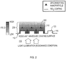
- Figure 2 schematically illustrates the electric field on the surface of a substrate 110 under a resonance condition.
- a light beam 210 impinges from a surface 114 (see Figure 1A ) of substrate 110 opposite to the surface 112.
- a plurality of upconverting nanoparticles 350 are bound to the surface 112 of grating structure 115, on which a refractive layer 120 is formed.
- the upconverting nanoparticles 350 may be conjugated to an antibody (not shown) that is directed to a target analyte (not shown).
- the target analyte is bound to the nanoparticle conjugated antibody and captured at the surface 112 by a second antibody (not shown) directed to the target analyte.
- the second antibody is bound to the surface 112 through a linkage chemistry 240 (for example, but not limited to, streptavidin, surface couplings via reactive functional groups such as amino, hydroxyl, thiol, and carboxyl groups, modified DNA probes, and peptides).
- a linkage chemistry 240 for example, but not limited to, streptavidin, surface couplings via reactive functional groups such as amino, hydroxyl, thiol, and carboxyl groups, modified DNA probes, and peptides.
- the wavelength of light beam 210 directed to surface 114 of substrate 110 matches a resonance condition of the grating structure 115 that constitutes a photonic crystal.
- the intensity of light beam 210 is greatly enhanced at an enhancement region 230 over a textured surface 117 of substrate 110.
- textured surface 117 is formed of grating structure 115 (parallel ridges and valleys), as shown in Figure 1B .
- textured surface 117 may be formed of an array of protrusions (e.g., pillars and rods), or an array of recesses (e.g., circular recesses, rectangular recesses, and hexagonal recesses).
- the enhancement of the light beam intensity can be as high as 1500-fold with respect to the intensity of light beam 210 without using a photonic crystal.
- the enhancement may be less than this and may reach around 50-fold.
- plasmonic surface structures made from metallic films.
- the emission of upconverting nanoparticles is enhanced almost 300-fold, using plasmonic nanoantenna (gold dots on pillar structures).
- plasmonic nanoantenna gold dots on pillar structures.
- the upconverting nanoparticles/labels are more robust and do not photobleach and last a long time compared to conventional fluorophores (e.g., several hours versus a few minutes for conventional fluorophores).
- the plasmonic structures are in general more difficult to manufacture and may have several drawbacks, such as strong light absorption that can cause heating effects.
- a transparent dielectric material avoids this problem.
- a high sensitivity system described herein for biomedical assay sensing applications includes two components.
- a first component is a sensor comprising a resonance grating structure made from a transparent dielectric material, such as a photonic crystal waveguide, and a secondary antibody directed to a target analyte that is bound to the surface of the resonance grating structure.
- a second component may comprise an upconverting nanoparticle bound to a primary antibody directed to the same target analyte as the secondary antibody.
- Conjugates other than an upconverting nanoparticle are also contemplated, for example, a conventional fluorophore or a downconverting nanoparticle.
- the system is designed for high sensitivity assay applications to provide low cost and ease of mass production and minimal background signal.
- the system of the present invention has improved sensitivity with the enhanced fields at enhancement region 230.
- the upconverting particles 350 are located in the enhancement region 230 of the resonance grating structure 100 which extends for more than a hundred nanometers from surface 112 of substrate 110.
- enhancement region 230 has a brightline boundary at surface 112, but a rather blurry boundary as the electric field which gradually diminishes away from surface 112.
- the blurry boundary may be defined as a contour line where the electric field is half of the strongest electric field proximate surface 112.
- the emission may be enhanced by about 50-fold or more, to improve the assay sensitivity.
- Grating structure 115 may have a grating period, a grating groove depth, a duty cycle, such that the resonance of grating 115 is tuned to the 980 nm absorption peak of the upconverting nanoparticles 350 and to normal incidence of the illuminating light source 210. In this case, there is substantially no background from the substrate 110 because the 980 nm light does not cause autofluorescence from grating 115 or from the body fluid sample being analyzed.
- the bioassay system according to the invention has additional advantages over conventional bioassay systems, such as immunoassay systems.
- the system does not suffer from photobleach of fluorophores.
- Upconverting nanoparticles 350 are known to be very stable and do not photobleach and can better handle the high electric fields proximate surface.
- Conventional fluorophores are less desirable and photobleach quickly.
- the system of the present invention has enhanced localized surface emission.
- Upconverting nanoparticles 350 have nonlinear absorption dependence with respect to the illumination intensity. Because of this nonlinear property, only bound nanoparticles, or those that are close to the surface, are excited selectively. As a result, there is little emission from the surrounding media.
- system of the present invention is applicable in homogeneous assay applications. Because of the enhanced surface-emission of bound nanoparticles, the assay washing step can be eliminated leading to a much simpler system design.
- the system of the present invention does not require focused light illumination.
- a laser or a coherent light source
- the enhancement effect from the resonance grating increases the intensity without the need for focusing and high power of lasers.
- Low-cost incoherent sources for example, but not limited to, LED, gas discharge lamps, and high-intensity discharge lamps can be used instead of a laser.
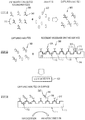
- FIG. 3 schematically illustrates a method for detecting analytes using a bioassay apparatus in accordance with the present invention.
- a composition of matter 345 comprising a nanoparticle 350 conjugated to a first antibody 340 targeted to a target analyte 330 is mixed with a body fluid such as blood, serum, plasma, synovial fluid, cerebrospinal fluid , or urine in which the target analyte 330 is suspected to be present.
- the composition of matter 345 may be formed by mixing nanoparticles 350 and first antibodies 340 directed to the target analyte in an organic or inorganic solvent for coupling nanoparticles to antibodies.
- the nanoparticle labeled antibodies may be a powder form that is mixed in the fluid containing the suspected analytes 330 to be detected.
- Bioassay sensor 300 may comprise a substrate 110 having a grating structure 310, a refractive layer 120 formed on the surface of grating structure 310, and second antibodies 320 directed to the target analyte 330 coupled and immobilized to a surface 312 of grating structure 310.
- Each grating period of grating structure 310 may comprise an anti-target antibody coupled therewith to constitute a target analyte capturing site 305.
- Second antibodies 320 may be immobilized on grating structure 310 through linkage chemistry 315 (e.g., streptavidin) to capture target analytes 330 coupled to, for example, a nanoparticle selected from the group consisting of NaYF4: Yb-Er, CaF2:Yb,Er, NaYbF4:Ho,Tm, Er from the body fluid of a patient being analyzed.
- Captured analytes 360 are bound to second antibodies 320 that are directed to the same target analytes 330 and are coupled to the surface 312 of grating structure 300.
- Bioassay sensor 300 may be washed by pure water to remove uncaptured analytes from substrate 110. Bioassay sensor 300 is now ready for optical examination.
- Step 30 light, e.g., a near-infrared (NIR) light beam having a wavelength of about 980 nm is applied to a surface 114 of substrate 110 that is on the side of the substrate 110 of grating structure 300 opposite to the surface 312 which may include refractive layer 120. Because the NIR light beam is chosen to match the resonance condition of grating structure 310, the upconverting nanoparticles 350 conjugated to the first antibody 340 directed to the target analyte 330 and bound to the grating surface 312 through the second antibody 320 also directed to the target analyte 330 are excited by an enhanced NIR excitation.
- NIR near-infrared
- a light beam (such as visible light) is emitted in response to the enhanced NIR excitation.
- the presence and/or absence of analytes 330 on capturing sites 350 is determined using a light detector 400.
- An upconverting nanoparticle 350 may be conjugated to an antibody 340 in a "sandwich" assay to detect the captured target analyte 330 bound to a second antibody directed to the target analyte 330 at capturing sites 305 on the surface of a resonant grating structure 310.
- the resonance of grating structure 310 is tuned to the peak of their absorption peak to have the largest enhancement effect and to improve the assay sensitivity.
- the bioassay sensor may be used in a "blocking assay” application where binding of particles to the surface of the resonant grating structure 310 leads to “detuning" of the resonance mode and reduction of the enhancement effect.
- the surface binding events result in change of the refractive index of refractive layer 120 and are enough to detune the resonance away from the illumination wavelength.
- a laser with a very narrow wavelength bandwidth and a grating with a high quality factor resonance structure, or a very narrow and sharp resonance peak is a very sensitive arrangement for detecting changes to the refractive index at the surface. As the resonance gets detuned away from the laser wavelength, a sharp drop in the enhanced emission of the upconverting nanoparticles may be observed.
- the sensing system of the present invention may take advantage of the relatively narrow enhancement region where the enhancement takes place and is useful to detect binding kinetics and follow changes in the quantity of target analyte over time. Not to be bound by theory but it is believed that the emission from upconverting particles captured at the surface of the grating structure is confined to less than a 100 nm region proximate the grating surface. Any upconverting nanoparticle labels outside the 100 nm region are not excited and consequently have much less emission than nanoparticles that are positioned closer to the surface of the grating structure and within the 100 nm region.
- the grating surface 312 may first be pretreated with labels (such as fluorophores or nanoparticles) by predefined linkage elements (such as thrombin) that are susceptible to cleavage by the action of a target protein.
- labels such as fluorophores or nanoparticles
- linkage elements such as thrombin
- the labels When exposed to thrombin, the labels are cleaved at the linkage element and diffuse away from the enhancement region.
- cleavage of the linkage element frees the label away from the surface in the 100 nm region above the grating structure and the label cannot be detected. Decreased emission allows for quantitative determination of a target protein, such as thrombin.
- the labels can specifically bind to the surface 312 and increase the signal indicating the binding events.
- the bioassay system is configured in a competitive heterogeneous immunoassay mode where a target analyte 330A, for example, is bound to an upconverting nanoparticle to form a nanoparticle labeled conjugated analyte 360.
- the target analyte 330B in the patient's body fluid sample is unlabeled.
- the nanoparticle labeled conjugated analyte 360 is then applied to bioassay sensor 300, such that capturing sites 305 are bound with a conjugated analyte 360.
- the patient's body fluid including unlabeled analytes 330B undergoing analysis is applied to the resultant "labeled" bioassay sensor 300.
- the patient's unlabeled target analyte 330B competes for binding sites 305 on the grating surface-coupled anti-target analyte antibody 320 with the nanoparticle labeled target analyte 360.
- the labeled target analytes 360 are released from the grating surface 312 and are free to diffuse into the solution away from the enhancement region 230 (see Figure 2 ).
- Detectable light emission arising from the nanoparticle labeled target analyte 360 decreases in the presence of patient unlabeled analyte 330B. This configuration is commonly used in drug analysis and in clinical biochemistry of hormones and proteins.
- unlabeled analyte 330B in the patient sample competes with nanoparticle-labeled analyte 360 at the enhancing surface 312.
- the unbound analyte is washed away, and the remaining labeled analyte 370 bound to the grating surface is measured.
- a decrease in emission of the labeled bound analyte 360 is proportional to the amount of target analyte in the patient's body fluid sample.
Landscapes
- Health & Medical Sciences (AREA)
- Life Sciences & Earth Sciences (AREA)
- Immunology (AREA)
- Engineering & Computer Science (AREA)
- Chemical & Material Sciences (AREA)
- Physics & Mathematics (AREA)
- Urology & Nephrology (AREA)
- Molecular Biology (AREA)
- Hematology (AREA)
- Biomedical Technology (AREA)
- Analytical Chemistry (AREA)
- General Health & Medical Sciences (AREA)
- Pathology (AREA)
- General Physics & Mathematics (AREA)
- Biochemistry (AREA)
- Food Science & Technology (AREA)
- Biotechnology (AREA)
- Cell Biology (AREA)
- Microbiology (AREA)
- Medicinal Chemistry (AREA)
- Nanotechnology (AREA)
- Materials Engineering (AREA)
- Plasma & Fusion (AREA)
- Chemical Kinetics & Catalysis (AREA)
- Crystallography & Structural Chemistry (AREA)
- Nuclear Medicine, Radiotherapy & Molecular Imaging (AREA)
- Investigating, Analyzing Materials By Fluorescence Or Luminescence (AREA)
- Investigating Or Analysing Materials By The Use Of Chemical Reactions (AREA)
Applications Claiming Priority (2)
| Application Number | Priority Date | Filing Date | Title |
|---|---|---|---|
| US201461969371P | 2014-03-24 | 2014-03-24 | |
| PCT/US2015/021651 WO2015148290A1 (en) | 2014-03-24 | 2015-03-20 | Bioassay system and method for detecting analytes in body fluids |
Publications (2)
| Publication Number | Publication Date |
|---|---|
| EP3123172A1 EP3123172A1 (en) | 2017-02-01 |
| EP3123172B1 true EP3123172B1 (en) | 2021-01-13 |
Family
ID=52991948
Family Applications (1)
| Application Number | Title | Priority Date | Filing Date |
|---|---|---|---|
| EP15717699.1A Active EP3123172B1 (en) | 2014-03-24 | 2015-03-20 | Bioassay system and method for detecting analytes in body fluids |
Country Status (8)
| Country | Link |
|---|---|
| US (1) | US20150268237A1 (ja) |
| EP (1) | EP3123172B1 (ja) |
| JP (1) | JP6606509B2 (ja) |
| CN (1) | CN106461559B (ja) |
| AU (1) | AU2015236470B2 (ja) |
| CA (1) | CA2943254C (ja) |
| ES (1) | ES2854352T3 (ja) |
| WO (1) | WO2015148290A1 (ja) |
Families Citing this family (11)
| Publication number | Priority date | Publication date | Assignee | Title |
|---|---|---|---|---|
| WO2017138595A1 (ja) * | 2016-02-09 | 2017-08-17 | 積水化学工業株式会社 | 検査用器具、検査装置及び検査方法 |
| JP6633978B2 (ja) * | 2016-06-17 | 2020-01-22 | 積水化学工業株式会社 | 検査キット及び検査方法 |
| US10877192B2 (en) | 2017-04-18 | 2020-12-29 | Saudi Arabian Oil Company | Method of fabricating smart photonic structures for material monitoring |
| US10401155B2 (en) | 2017-05-12 | 2019-09-03 | Saudi Arabian Oil Company | Apparatus and method for smart material analysis |
| CN110720040A (zh) * | 2017-06-08 | 2020-01-21 | 卢米托股份有限公司 | 分析至少一种分析物的样本的方法 |
| CN107356570B (zh) * | 2017-06-08 | 2020-10-27 | 大连海事大学 | 一种固态上转换荧光探针及其制备方法与应用 |
| US10746534B2 (en) | 2017-07-03 | 2020-08-18 | Saudi Arabian Oil Company | Smart coating device for storage tank monitoring and calibration |
| CN108163802B (zh) * | 2017-12-06 | 2020-02-07 | 北京纳百生物科技有限公司 | 一种抗原检测材料及其制备方法和应用 |
| CN112313501A (zh) * | 2018-07-31 | 2021-02-02 | 积水化学工业株式会社 | 检测方法、检测用器具和检测装置 |
| CN108957839B (zh) * | 2018-08-09 | 2022-09-30 | 京东方科技集团股份有限公司 | 显示装置、显示面板、彩膜基板及彩膜 |
| CN109470652A (zh) * | 2018-10-24 | 2019-03-15 | 北京邮电大学 | 基于Fano谐振的椭圆空气孔部分刻蚀型光子晶体传感器 |
Family Cites Families (14)
| Publication number | Priority date | Publication date | Assignee | Title |
|---|---|---|---|---|
| US4208479A (en) * | 1977-07-14 | 1980-06-17 | Syva Company | Label modified immunoassays |
| ES2123063T3 (es) * | 1992-09-14 | 1999-01-01 | Stanford Res Inst Int | Marcadores convertidores al alza para ensayos biologicos y otros mediante tecnicas de excitacion laser. |
| JP2001116699A (ja) * | 1999-10-21 | 2001-04-27 | Ngk Insulators Ltd | 遺伝子診断方法 |
| US6951715B2 (en) * | 2000-10-30 | 2005-10-04 | Sru Biosystems, Inc. | Optical detection of label-free biomolecular interactions using microreplicated plastic sensor elements |
| US6560020B1 (en) * | 2001-01-16 | 2003-05-06 | Holotek, Llc | Surface-relief diffraction grating |
| US7008559B2 (en) * | 2001-06-06 | 2006-03-07 | Nomadics, Inc. | Manganese doped upconversion luminescence nanoparticles |
| JP4751328B2 (ja) * | 2003-03-27 | 2011-08-17 | コーニング インコーポレイテッド | 生物剤と化学剤の、標識を用いないエバネッセント場検出 |
| JP2007240361A (ja) * | 2006-03-09 | 2007-09-20 | Sekisui Chem Co Ltd | 局在プラズモン増強センサ |
| EP1912067A1 (en) * | 2006-10-12 | 2008-04-16 | Eppendorf Array Technologies S.A. | Method for quantification of a target compound obtained from a biological sample upon chips |
| WO2010072383A1 (en) * | 2008-12-22 | 2010-07-01 | 7Roche Diagnostics Gmbh | Armet as a marker for cancer |
| CN102375060B (zh) * | 2010-08-19 | 2014-12-31 | 中国人民解放军军事医学科学院微生物流行病研究所 | 一种基于上转换发光十通道免疫层析的食源性致病菌检测试纸盘 |
| US20140364795A1 (en) * | 2011-12-19 | 2014-12-11 | Nanyang Technological University | Synthesis of upconversion nanocomposites for photodynamic therapy |
| JP5975480B2 (ja) * | 2012-01-31 | 2016-08-23 | 国立研究開発法人産業技術総合研究所 | バイオチップ、バイオアッセイ用キット、及びバイオアッセイ方法 |
| SG11201408520QA (en) * | 2012-07-12 | 2015-03-30 | Univ Singapore | An upconversion fluorescent nanoparticle |
-
2015
- 2015-03-20 WO PCT/US2015/021651 patent/WO2015148290A1/en active Application Filing
- 2015-03-20 JP JP2016558198A patent/JP6606509B2/ja active Active
- 2015-03-20 CN CN201580025617.1A patent/CN106461559B/zh active Active
- 2015-03-20 ES ES15717699T patent/ES2854352T3/es active Active
- 2015-03-20 AU AU2015236470A patent/AU2015236470B2/en active Active
- 2015-03-20 US US14/663,560 patent/US20150268237A1/en active Pending
- 2015-03-20 CA CA2943254A patent/CA2943254C/en active Active
- 2015-03-20 EP EP15717699.1A patent/EP3123172B1/en active Active
Non-Patent Citations (1)
| Title |
|---|
| None * |
Also Published As
| Publication number | Publication date |
|---|---|
| WO2015148290A1 (en) | 2015-10-01 |
| CA2943254C (en) | 2021-05-04 |
| AU2015236470A1 (en) | 2016-10-06 |
| US20150268237A1 (en) | 2015-09-24 |
| JP6606509B2 (ja) | 2019-11-13 |
| ES2854352T3 (es) | 2021-09-21 |
| CN106461559B (zh) | 2020-07-03 |
| CA2943254A1 (en) | 2015-10-01 |
| AU2015236470B2 (en) | 2019-03-07 |
| CN106461559A (zh) | 2017-02-22 |
| JP2017508975A (ja) | 2017-03-30 |
| EP3123172A1 (en) | 2017-02-01 |
Similar Documents
| Publication | Publication Date | Title |
|---|---|---|
| EP3123172B1 (en) | Bioassay system and method for detecting analytes in body fluids | |
| US9395363B2 (en) | SPR sensor device with nanostructure | |
| JP2010518389A (ja) | エバネセント導波管及び集積センサを用いるバイオセンサ | |
| JP2009511896A (ja) | 全ポリマー光導波路センサ | |
| WO2008136812A2 (en) | Fluorescence detection enhancement using photonic crystal extraction | |
| JP4885019B2 (ja) | 表面プラズモン増強蛍光センサ | |
| JP2011503536A (ja) | マイクロエレクトロニクスセンサ | |
| JP2009244018A (ja) | 蛍光検出方法および蛍光検出装置 | |
| US20230017547A1 (en) | Digital microfluidic (dmf) system, dmf cartridge, and method including integrated optical fiber sensing | |
| JP2009216532A (ja) | 蛍光検出方法および蛍光検出装置 | |
| Wu et al. | Magnification of photonic crystal fluorescence enhancement via TM resonance excitation and TE resonance extraction on a dielectric nanorod surface | |
| EP2060904A1 (en) | Plasmon grating biosensor | |
| US9157861B2 (en) | Sensor and method of detecting a target analyte | |
| JP2009080011A (ja) | 蛍光検出方法 | |
| Stringer et al. | Quantum dot-based biosensor for detection of human cardiac troponin I using a liquid-core waveguide | |
| EP3474002A1 (en) | Simple sensing method employing raman scattering | |
| JP2012530894A (ja) | 発光ダイオードにより光学的マイクロキャビティを動作させるための装置及び方法 | |
| JP4480130B2 (ja) | 光学分析装置 | |
| WO2014007134A1 (ja) | センサーチップ | |
| WO2021131331A1 (ja) | 蛍光検出用生体分子検査チップ | |
| RU2494374C2 (ru) | Устройство микроэлектронного датчика | |
| Välimäki et al. | A novel platform for highly surface-sensitive fluorescent measurements applying simultaneous total internal reflection excitation and super critical angle detection | |
| JP2011127991A (ja) | プラズモン励起センサおよび該センサを用いたアッセイ法 | |
| Le et al. | Surface plasmon enhanced upconversion luminescence for biosensing applications | |
| Toma et al. | Fluorescence Biosensors Utilizing Grating‐Assisted Plasmonic Amplification |
Legal Events
| Date | Code | Title | Description |
|---|---|---|---|
| STAA | Information on the status of an ep patent application or granted ep patent |
Free format text: STATUS: THE INTERNATIONAL PUBLICATION HAS BEEN MADE |
|
| PUAI | Public reference made under article 153(3) epc to a published international application that has entered the european phase |
Free format text: ORIGINAL CODE: 0009012 |
|
| STAA | Information on the status of an ep patent application or granted ep patent |
Free format text: STATUS: REQUEST FOR EXAMINATION WAS MADE |
|
| 17P | Request for examination filed |
Effective date: 20160921 |
|
| AK | Designated contracting states |
Kind code of ref document: A1 Designated state(s): AL AT BE BG CH CY CZ DE DK EE ES FI FR GB GR HR HU IE IS IT LI LT LU LV MC MK MT NL NO PL PT RO RS SE SI SK SM TR |
|
| AX | Request for extension of the european patent |
Extension state: BA ME |
|
| DAV | Request for validation of the european patent (deleted) | ||
| DAX | Request for extension of the european patent (deleted) | ||
| STAA | Information on the status of an ep patent application or granted ep patent |
Free format text: STATUS: EXAMINATION IS IN PROGRESS |
|
| 17Q | First examination report despatched |
Effective date: 20180305 |
|
| GRAP | Despatch of communication of intention to grant a patent |
Free format text: ORIGINAL CODE: EPIDOSNIGR1 |
|
| STAA | Information on the status of an ep patent application or granted ep patent |
Free format text: STATUS: GRANT OF PATENT IS INTENDED |
|
| RIC1 | Information provided on ipc code assigned before grant |
Ipc: G01N 21/77 20060101ALI20200910BHEP Ipc: G01N 33/543 20060101AFI20200910BHEP Ipc: G01N 21/65 20060101ALI20200910BHEP Ipc: G01N 33/58 20060101ALI20200910BHEP |
|
| INTG | Intention to grant announced |
Effective date: 20200928 |
|
| GRAS | Grant fee paid |
Free format text: ORIGINAL CODE: EPIDOSNIGR3 |
|
| GRAA | (expected) grant |
Free format text: ORIGINAL CODE: 0009210 |
|
| STAA | Information on the status of an ep patent application or granted ep patent |
Free format text: STATUS: THE PATENT HAS BEEN GRANTED |
|
| AK | Designated contracting states |
Kind code of ref document: B1 Designated state(s): AL AT BE BG CH CY CZ DE DK EE ES FI FR GB GR HR HU IE IS IT LI LT LU LV MC MK MT NL NO PL PT RO RS SE SI SK SM TR |
|
| REG | Reference to a national code |
Ref country code: GB Ref legal event code: FG4D |
|
| REG | Reference to a national code |
Ref country code: CH Ref legal event code: EP |
|
| REG | Reference to a national code |
Ref country code: DE Ref legal event code: R096 Ref document number: 602015064699 Country of ref document: DE |
|
| REG | Reference to a national code |
Ref country code: IE Ref legal event code: FG4D |
|
| REG | Reference to a national code |
Ref country code: AT Ref legal event code: REF Ref document number: 1354958 Country of ref document: AT Kind code of ref document: T Effective date: 20210215 |
|
| REG | Reference to a national code |
Ref country code: AT Ref legal event code: MK05 Ref document number: 1354958 Country of ref document: AT Kind code of ref document: T Effective date: 20210113 |
|
| REG | Reference to a national code |
Ref country code: NL Ref legal event code: MP Effective date: 20210113 |
|
| REG | Reference to a national code |
Ref country code: LT Ref legal event code: MG9D |
|
| PG25 | Lapsed in a contracting state [announced via postgrant information from national office to epo] |
Ref country code: PT Free format text: LAPSE BECAUSE OF FAILURE TO SUBMIT A TRANSLATION OF THE DESCRIPTION OR TO PAY THE FEE WITHIN THE PRESCRIBED TIME-LIMIT Effective date: 20210513 Ref country code: LT Free format text: LAPSE BECAUSE OF FAILURE TO SUBMIT A TRANSLATION OF THE DESCRIPTION OR TO PAY THE FEE WITHIN THE PRESCRIBED TIME-LIMIT Effective date: 20210113 Ref country code: BG Free format text: LAPSE BECAUSE OF FAILURE TO SUBMIT A TRANSLATION OF THE DESCRIPTION OR TO PAY THE FEE WITHIN THE PRESCRIBED TIME-LIMIT Effective date: 20210413 Ref country code: NL Free format text: LAPSE BECAUSE OF FAILURE TO SUBMIT A TRANSLATION OF THE DESCRIPTION OR TO PAY THE FEE WITHIN THE PRESCRIBED TIME-LIMIT Effective date: 20210113 Ref country code: NO Free format text: LAPSE BECAUSE OF FAILURE TO SUBMIT A TRANSLATION OF THE DESCRIPTION OR TO PAY THE FEE WITHIN THE PRESCRIBED TIME-LIMIT Effective date: 20210413 Ref country code: FI Free format text: LAPSE BECAUSE OF FAILURE TO SUBMIT A TRANSLATION OF THE DESCRIPTION OR TO PAY THE FEE WITHIN THE PRESCRIBED TIME-LIMIT Effective date: 20210113 Ref country code: HR Free format text: LAPSE BECAUSE OF FAILURE TO SUBMIT A TRANSLATION OF THE DESCRIPTION OR TO PAY THE FEE WITHIN THE PRESCRIBED TIME-LIMIT Effective date: 20210113 Ref country code: GR Free format text: LAPSE BECAUSE OF FAILURE TO SUBMIT A TRANSLATION OF THE DESCRIPTION OR TO PAY THE FEE WITHIN THE PRESCRIBED TIME-LIMIT Effective date: 20210414 |
|
| PG25 | Lapsed in a contracting state [announced via postgrant information from national office to epo] |
Ref country code: AT Free format text: LAPSE BECAUSE OF FAILURE TO SUBMIT A TRANSLATION OF THE DESCRIPTION OR TO PAY THE FEE WITHIN THE PRESCRIBED TIME-LIMIT Effective date: 20210113 Ref country code: LV Free format text: LAPSE BECAUSE OF FAILURE TO SUBMIT A TRANSLATION OF THE DESCRIPTION OR TO PAY THE FEE WITHIN THE PRESCRIBED TIME-LIMIT Effective date: 20210113 Ref country code: PL Free format text: LAPSE BECAUSE OF FAILURE TO SUBMIT A TRANSLATION OF THE DESCRIPTION OR TO PAY THE FEE WITHIN THE PRESCRIBED TIME-LIMIT Effective date: 20210113 Ref country code: RS Free format text: LAPSE BECAUSE OF FAILURE TO SUBMIT A TRANSLATION OF THE DESCRIPTION OR TO PAY THE FEE WITHIN THE PRESCRIBED TIME-LIMIT Effective date: 20210113 Ref country code: SE Free format text: LAPSE BECAUSE OF FAILURE TO SUBMIT A TRANSLATION OF THE DESCRIPTION OR TO PAY THE FEE WITHIN THE PRESCRIBED TIME-LIMIT Effective date: 20210113 |
|
| REG | Reference to a national code |
Ref country code: ES Ref legal event code: FG2A Ref document number: 2854352 Country of ref document: ES Kind code of ref document: T3 Effective date: 20210921 |
|
| PG25 | Lapsed in a contracting state [announced via postgrant information from national office to epo] |
Ref country code: IS Free format text: LAPSE BECAUSE OF FAILURE TO SUBMIT A TRANSLATION OF THE DESCRIPTION OR TO PAY THE FEE WITHIN THE PRESCRIBED TIME-LIMIT Effective date: 20210513 |
|
| REG | Reference to a national code |
Ref country code: DE Ref legal event code: R097 Ref document number: 602015064699 Country of ref document: DE |
|
| PG25 | Lapsed in a contracting state [announced via postgrant information from national office to epo] |
Ref country code: SM Free format text: LAPSE BECAUSE OF FAILURE TO SUBMIT A TRANSLATION OF THE DESCRIPTION OR TO PAY THE FEE WITHIN THE PRESCRIBED TIME-LIMIT Effective date: 20210113 Ref country code: MC Free format text: LAPSE BECAUSE OF FAILURE TO SUBMIT A TRANSLATION OF THE DESCRIPTION OR TO PAY THE FEE WITHIN THE PRESCRIBED TIME-LIMIT Effective date: 20210113 Ref country code: EE Free format text: LAPSE BECAUSE OF FAILURE TO SUBMIT A TRANSLATION OF THE DESCRIPTION OR TO PAY THE FEE WITHIN THE PRESCRIBED TIME-LIMIT Effective date: 20210113 Ref country code: CZ Free format text: LAPSE BECAUSE OF FAILURE TO SUBMIT A TRANSLATION OF THE DESCRIPTION OR TO PAY THE FEE WITHIN THE PRESCRIBED TIME-LIMIT Effective date: 20210113 |
|
| REG | Reference to a national code |
Ref country code: CH Ref legal event code: PL |
|
| PLBE | No opposition filed within time limit |
Free format text: ORIGINAL CODE: 0009261 |
|
| STAA | Information on the status of an ep patent application or granted ep patent |
Free format text: STATUS: NO OPPOSITION FILED WITHIN TIME LIMIT |
|
| PG25 | Lapsed in a contracting state [announced via postgrant information from national office to epo] |
Ref country code: RO Free format text: LAPSE BECAUSE OF FAILURE TO SUBMIT A TRANSLATION OF THE DESCRIPTION OR TO PAY THE FEE WITHIN THE PRESCRIBED TIME-LIMIT Effective date: 20210113 Ref country code: SK Free format text: LAPSE BECAUSE OF FAILURE TO SUBMIT A TRANSLATION OF THE DESCRIPTION OR TO PAY THE FEE WITHIN THE PRESCRIBED TIME-LIMIT Effective date: 20210113 Ref country code: DK Free format text: LAPSE BECAUSE OF FAILURE TO SUBMIT A TRANSLATION OF THE DESCRIPTION OR TO PAY THE FEE WITHIN THE PRESCRIBED TIME-LIMIT Effective date: 20210113 |
|
| REG | Reference to a national code |
Ref country code: BE Ref legal event code: MM Effective date: 20210331 |
|
| 26N | No opposition filed |
Effective date: 20211014 |
|
| PG25 | Lapsed in a contracting state [announced via postgrant information from national office to epo] |
Ref country code: AL Free format text: LAPSE BECAUSE OF FAILURE TO SUBMIT A TRANSLATION OF THE DESCRIPTION OR TO PAY THE FEE WITHIN THE PRESCRIBED TIME-LIMIT Effective date: 20210113 Ref country code: CH Free format text: LAPSE BECAUSE OF NON-PAYMENT OF DUE FEES Effective date: 20210331 Ref country code: LI Free format text: LAPSE BECAUSE OF NON-PAYMENT OF DUE FEES Effective date: 20210331 Ref country code: LU Free format text: LAPSE BECAUSE OF NON-PAYMENT OF DUE FEES Effective date: 20210320 Ref country code: IE Free format text: LAPSE BECAUSE OF NON-PAYMENT OF DUE FEES Effective date: 20210320 |
|
| PG25 | Lapsed in a contracting state [announced via postgrant information from national office to epo] |
Ref country code: SI Free format text: LAPSE BECAUSE OF FAILURE TO SUBMIT A TRANSLATION OF THE DESCRIPTION OR TO PAY THE FEE WITHIN THE PRESCRIBED TIME-LIMIT Effective date: 20210113 |
|
| PG25 | Lapsed in a contracting state [announced via postgrant information from national office to epo] |
Ref country code: IS Free format text: LAPSE BECAUSE OF FAILURE TO SUBMIT A TRANSLATION OF THE DESCRIPTION OR TO PAY THE FEE WITHIN THE PRESCRIBED TIME-LIMIT Effective date: 20210513 |
|
| PG25 | Lapsed in a contracting state [announced via postgrant information from national office to epo] |
Ref country code: BE Free format text: LAPSE BECAUSE OF NON-PAYMENT OF DUE FEES Effective date: 20210331 |
|
| PG25 | Lapsed in a contracting state [announced via postgrant information from national office to epo] |
Ref country code: HU Free format text: LAPSE BECAUSE OF FAILURE TO SUBMIT A TRANSLATION OF THE DESCRIPTION OR TO PAY THE FEE WITHIN THE PRESCRIBED TIME-LIMIT; INVALID AB INITIO Effective date: 20150320 |
|
| P01 | Opt-out of the competence of the unified patent court (upc) registered |
Effective date: 20230522 |
|
| PG25 | Lapsed in a contracting state [announced via postgrant information from national office to epo] |
Ref country code: CY Free format text: LAPSE BECAUSE OF FAILURE TO SUBMIT A TRANSLATION OF THE DESCRIPTION OR TO PAY THE FEE WITHIN THE PRESCRIBED TIME-LIMIT Effective date: 20210113 |
|
| PG25 | Lapsed in a contracting state [announced via postgrant information from national office to epo] |
Ref country code: MK Free format text: LAPSE BECAUSE OF FAILURE TO SUBMIT A TRANSLATION OF THE DESCRIPTION OR TO PAY THE FEE WITHIN THE PRESCRIBED TIME-LIMIT Effective date: 20210113 |
|
| PGFP | Annual fee paid to national office [announced via postgrant information from national office to epo] |
Ref country code: DE Payment date: 20240327 Year of fee payment: 10 Ref country code: GB Payment date: 20240327 Year of fee payment: 10 |
|
| PGFP | Annual fee paid to national office [announced via postgrant information from national office to epo] |
Ref country code: IT Payment date: 20240321 Year of fee payment: 10 Ref country code: FR Payment date: 20240325 Year of fee payment: 10 |
|
| PG25 | Lapsed in a contracting state [announced via postgrant information from national office to epo] |
Ref country code: TR Free format text: LAPSE BECAUSE OF FAILURE TO SUBMIT A TRANSLATION OF THE DESCRIPTION OR TO PAY THE FEE WITHIN THE PRESCRIBED TIME-LIMIT Effective date: 20210113 |
|
| PGFP | Annual fee paid to national office [announced via postgrant information from national office to epo] |
Ref country code: ES Payment date: 20240401 Year of fee payment: 10 |
|
| REG | Reference to a national code |
Ref country code: DE Ref legal event code: R082 Ref document number: 602015064699 Country of ref document: DE Representative=s name: STRAUS, ALEXANDER, DIPL.-CHEM.UNIV. DR.PHIL., DE |