EP3122401B1 - Compact mechanical pump - Google Patents
Compact mechanical pump Download PDFInfo
- Publication number
- EP3122401B1 EP3122401B1 EP15770109.5A EP15770109A EP3122401B1 EP 3122401 B1 EP3122401 B1 EP 3122401B1 EP 15770109 A EP15770109 A EP 15770109A EP 3122401 B1 EP3122401 B1 EP 3122401B1
- Authority
- EP
- European Patent Office
- Prior art keywords
- cover
- base
- section
- puller
- base section
- Prior art date
- Legal status (The legal status is an assumption and is not a legal conclusion. Google has not performed a legal analysis and makes no representation as to the accuracy of the status listed.)
- Active
Links
- 239000012530 fluid Substances 0.000 claims description 23
- 230000000295 complement effect Effects 0.000 description 45
- 238000001802 infusion Methods 0.000 description 20
- 239000007788 liquid Substances 0.000 description 16
- 230000001225 therapeutic effect Effects 0.000 description 10
- 239000004033 plastic Substances 0.000 description 7
- 229920003023 plastic Polymers 0.000 description 7
- 230000008878 coupling Effects 0.000 description 6
- 238000010168 coupling process Methods 0.000 description 6
- 238000005859 coupling reaction Methods 0.000 description 6
- 238000002560 therapeutic procedure Methods 0.000 description 6
- 108060003951 Immunoglobulin Proteins 0.000 description 5
- 229910052782 aluminium Inorganic materials 0.000 description 5
- XAGFODPZIPBFFR-UHFFFAOYSA-N aluminium Chemical compound [Al] XAGFODPZIPBFFR-UHFFFAOYSA-N 0.000 description 5
- 102000018358 immunoglobulin Human genes 0.000 description 5
- 238000002347 injection Methods 0.000 description 4
- 239000007924 injection Substances 0.000 description 4
- 229910052751 metal Inorganic materials 0.000 description 4
- 239000002184 metal Substances 0.000 description 4
- 238000000926 separation method Methods 0.000 description 4
- 238000003860 storage Methods 0.000 description 4
- 238000001990 intravenous administration Methods 0.000 description 3
- 230000007246 mechanism Effects 0.000 description 3
- 238000000034 method Methods 0.000 description 3
- 230000002093 peripheral effect Effects 0.000 description 3
- 238000002360 preparation method Methods 0.000 description 3
- 238000007920 subcutaneous administration Methods 0.000 description 3
- 206010022004 Influenza like illness Diseases 0.000 description 2
- 239000003242 anti bacterial agent Substances 0.000 description 2
- 230000000712 assembly Effects 0.000 description 2
- 238000000429 assembly Methods 0.000 description 2
- 239000003814 drug Substances 0.000 description 2
- 230000006870 function Effects 0.000 description 2
- 239000000463 material Substances 0.000 description 2
- 229940124597 therapeutic agent Drugs 0.000 description 2
- 229910000677 High-carbon steel Inorganic materials 0.000 description 1
- 206010061598 Immunodeficiency Diseases 0.000 description 1
- 208000029462 Immunodeficiency disease Diseases 0.000 description 1
- 239000004676 acrylonitrile butadiene styrene Substances 0.000 description 1
- 238000002048 anodisation reaction Methods 0.000 description 1
- 229940088710 antibiotic agent Drugs 0.000 description 1
- 239000002246 antineoplastic agent Substances 0.000 description 1
- 230000004888 barrier function Effects 0.000 description 1
- 230000003115 biocidal effect Effects 0.000 description 1
- 238000001815 biotherapy Methods 0.000 description 1
- 230000036765 blood level Effects 0.000 description 1
- 239000002738 chelating agent Substances 0.000 description 1
- 239000011248 coating agent Substances 0.000 description 1
- 238000000576 coating method Methods 0.000 description 1
- 230000006835 compression Effects 0.000 description 1
- 238000007906 compression Methods 0.000 description 1
- 229940127089 cytotoxic agent Drugs 0.000 description 1
- 230000000881 depressing effect Effects 0.000 description 1
- -1 e.g. Substances 0.000 description 1
- 238000001914 filtration Methods 0.000 description 1
- 239000011521 glass Substances 0.000 description 1
- 230000007813 immunodeficiency Effects 0.000 description 1
- 238000007373 indentation Methods 0.000 description 1
- 238000002642 intravenous therapy Methods 0.000 description 1
- 210000001503 joint Anatomy 0.000 description 1
- 239000000314 lubricant Substances 0.000 description 1
- 238000004519 manufacturing process Methods 0.000 description 1
- 239000002905 metal composite material Substances 0.000 description 1
- 238000012986 modification Methods 0.000 description 1
- 230000004048 modification Effects 0.000 description 1
- 229910001000 nickel titanium Inorganic materials 0.000 description 1
- 229910000623 nickel–chromium alloy Inorganic materials 0.000 description 1
- 229910052755 nonmetal Inorganic materials 0.000 description 1
- 238000005086 pumping Methods 0.000 description 1
- 238000010926 purge Methods 0.000 description 1
- 230000009467 reduction Effects 0.000 description 1
- 230000000284 resting effect Effects 0.000 description 1
- 229910001285 shape-memory alloy Inorganic materials 0.000 description 1
- 239000007787 solid Substances 0.000 description 1
- 229910001220 stainless steel Inorganic materials 0.000 description 1
- 239000010935 stainless steel Substances 0.000 description 1
- 230000009466 transformation Effects 0.000 description 1
- 239000012780 transparent material Substances 0.000 description 1
- 230000001960 triggered effect Effects 0.000 description 1
- 230000003442 weekly effect Effects 0.000 description 1
Images


Classifications
-
- A—HUMAN NECESSITIES
- A61—MEDICAL OR VETERINARY SCIENCE; HYGIENE
- A61M—DEVICES FOR INTRODUCING MEDIA INTO, OR ONTO, THE BODY; DEVICES FOR TRANSDUCING BODY MEDIA OR FOR TAKING MEDIA FROM THE BODY; DEVICES FOR PRODUCING OR ENDING SLEEP OR STUPOR
- A61M5/00—Devices for bringing media into the body in a subcutaneous, intra-vascular or intramuscular way; Accessories therefor, e.g. filling or cleaning devices, arm-rests
- A61M5/14—Infusion devices, e.g. infusing by gravity; Blood infusion; Accessories therefor
- A61M5/142—Pressure infusion, e.g. using pumps
- A61M5/145—Pressure infusion, e.g. using pumps using pressurised reservoirs, e.g. pressurised by means of pistons
- A61M5/1452—Pressure infusion, e.g. using pumps using pressurised reservoirs, e.g. pressurised by means of pistons pressurised by means of pistons
- A61M5/1454—Pressure infusion, e.g. using pumps using pressurised reservoirs, e.g. pressurised by means of pistons pressurised by means of pistons spring-actuated, e.g. by a clockwork
-
- A—HUMAN NECESSITIES
- A61—MEDICAL OR VETERINARY SCIENCE; HYGIENE
- A61M—DEVICES FOR INTRODUCING MEDIA INTO, OR ONTO, THE BODY; DEVICES FOR TRANSDUCING BODY MEDIA OR FOR TAKING MEDIA FROM THE BODY; DEVICES FOR PRODUCING OR ENDING SLEEP OR STUPOR
- A61M5/00—Devices for bringing media into the body in a subcutaneous, intra-vascular or intramuscular way; Accessories therefor, e.g. filling or cleaning devices, arm-rests
- A61M5/14—Infusion devices, e.g. infusing by gravity; Blood infusion; Accessories therefor
- A61M5/142—Pressure infusion, e.g. using pumps
- A61M5/14244—Pressure infusion, e.g. using pumps adapted to be carried by the patient, e.g. portable on the body
-
- A—HUMAN NECESSITIES
- A61—MEDICAL OR VETERINARY SCIENCE; HYGIENE
- A61M—DEVICES FOR INTRODUCING MEDIA INTO, OR ONTO, THE BODY; DEVICES FOR TRANSDUCING BODY MEDIA OR FOR TAKING MEDIA FROM THE BODY; DEVICES FOR PRODUCING OR ENDING SLEEP OR STUPOR
- A61M5/00—Devices for bringing media into the body in a subcutaneous, intra-vascular or intramuscular way; Accessories therefor, e.g. filling or cleaning devices, arm-rests
- A61M5/178—Syringes
- A61M5/24—Ampoule syringes, i.e. syringes with needle for use in combination with replaceable ampoules or carpules, e.g. automatic
-
- A—HUMAN NECESSITIES
- A61—MEDICAL OR VETERINARY SCIENCE; HYGIENE
- A61M—DEVICES FOR INTRODUCING MEDIA INTO, OR ONTO, THE BODY; DEVICES FOR TRANSDUCING BODY MEDIA OR FOR TAKING MEDIA FROM THE BODY; DEVICES FOR PRODUCING OR ENDING SLEEP OR STUPOR
- A61M5/00—Devices for bringing media into the body in a subcutaneous, intra-vascular or intramuscular way; Accessories therefor, e.g. filling or cleaning devices, arm-rests
- A61M5/178—Syringes
- A61M5/31—Details
- A61M5/3129—Syringe barrels
-
- A—HUMAN NECESSITIES
- A61—MEDICAL OR VETERINARY SCIENCE; HYGIENE
- A61M—DEVICES FOR INTRODUCING MEDIA INTO, OR ONTO, THE BODY; DEVICES FOR TRANSDUCING BODY MEDIA OR FOR TAKING MEDIA FROM THE BODY; DEVICES FOR PRODUCING OR ENDING SLEEP OR STUPOR
- A61M5/00—Devices for bringing media into the body in a subcutaneous, intra-vascular or intramuscular way; Accessories therefor, e.g. filling or cleaning devices, arm-rests
- A61M5/178—Syringes
- A61M5/31—Details
- A61M5/315—Pistons; Piston-rods; Guiding, blocking or restricting the movement of the rod or piston; Appliances on the rod for facilitating dosing ; Dosing mechanisms
- A61M5/31511—Piston or piston-rod constructions, e.g. connection of piston with piston-rod
-
- A—HUMAN NECESSITIES
- A61—MEDICAL OR VETERINARY SCIENCE; HYGIENE
- A61M—DEVICES FOR INTRODUCING MEDIA INTO, OR ONTO, THE BODY; DEVICES FOR TRANSDUCING BODY MEDIA OR FOR TAKING MEDIA FROM THE BODY; DEVICES FOR PRODUCING OR ENDING SLEEP OR STUPOR
- A61M5/00—Devices for bringing media into the body in a subcutaneous, intra-vascular or intramuscular way; Accessories therefor, e.g. filling or cleaning devices, arm-rests
- A61M5/178—Syringes
- A61M5/20—Automatic syringes, e.g. with automatically actuated piston rod, with automatic needle injection, filling automatically
- A61M2005/2006—Having specific accessories
- A61M2005/202—Having specific accessories cocking means, e.g. to bias the main drive spring of an injector
-
- A—HUMAN NECESSITIES
- A61—MEDICAL OR VETERINARY SCIENCE; HYGIENE
- A61M—DEVICES FOR INTRODUCING MEDIA INTO, OR ONTO, THE BODY; DEVICES FOR TRANSDUCING BODY MEDIA OR FOR TAKING MEDIA FROM THE BODY; DEVICES FOR PRODUCING OR ENDING SLEEP OR STUPOR
- A61M5/00—Devices for bringing media into the body in a subcutaneous, intra-vascular or intramuscular way; Accessories therefor, e.g. filling or cleaning devices, arm-rests
- A61M5/178—Syringes
- A61M5/24—Ampoule syringes, i.e. syringes with needle for use in combination with replaceable ampoules or carpules, e.g. automatic
- A61M2005/2477—Ampoule syringes, i.e. syringes with needle for use in combination with replaceable ampoules or carpules, e.g. automatic comprising means to reduce play of ampoule within ampoule holder, e.g. springs
-
- A—HUMAN NECESSITIES
- A61—MEDICAL OR VETERINARY SCIENCE; HYGIENE
- A61M—DEVICES FOR INTRODUCING MEDIA INTO, OR ONTO, THE BODY; DEVICES FOR TRANSDUCING BODY MEDIA OR FOR TAKING MEDIA FROM THE BODY; DEVICES FOR PRODUCING OR ENDING SLEEP OR STUPOR
- A61M5/00—Devices for bringing media into the body in a subcutaneous, intra-vascular or intramuscular way; Accessories therefor, e.g. filling or cleaning devices, arm-rests
- A61M5/178—Syringes
- A61M5/31—Details
- A61M5/3129—Syringe barrels
- A61M2005/314—Flat shaped barrel forms, e.g. credit card shaped
-
- A—HUMAN NECESSITIES
- A61—MEDICAL OR VETERINARY SCIENCE; HYGIENE
- A61M—DEVICES FOR INTRODUCING MEDIA INTO, OR ONTO, THE BODY; DEVICES FOR TRANSDUCING BODY MEDIA OR FOR TAKING MEDIA FROM THE BODY; DEVICES FOR PRODUCING OR ENDING SLEEP OR STUPOR
- A61M5/00—Devices for bringing media into the body in a subcutaneous, intra-vascular or intramuscular way; Accessories therefor, e.g. filling or cleaning devices, arm-rests
- A61M5/178—Syringes
- A61M5/31—Details
- A61M5/315—Pistons; Piston-rods; Guiding, blocking or restricting the movement of the rod or piston; Appliances on the rod for facilitating dosing ; Dosing mechanisms
- A61M5/31511—Piston or piston-rod constructions, e.g. connection of piston with piston-rod
- A61M2005/31518—Piston or piston-rod constructions, e.g. connection of piston with piston-rod designed to reduce the overall size of an injection device, e.g. using flexible or pivotally connected chain-like rod members
-
- A—HUMAN NECESSITIES
- A61—MEDICAL OR VETERINARY SCIENCE; HYGIENE
- A61M—DEVICES FOR INTRODUCING MEDIA INTO, OR ONTO, THE BODY; DEVICES FOR TRANSDUCING BODY MEDIA OR FOR TAKING MEDIA FROM THE BODY; DEVICES FOR PRODUCING OR ENDING SLEEP OR STUPOR
- A61M2205/00—General characteristics of the apparatus
- A61M2205/58—Means for facilitating use, e.g. by people with impaired vision
- A61M2205/583—Means for facilitating use, e.g. by people with impaired vision by visual feedback
Definitions
- the typical therapy for primary humoral immunodeficiency is intravenous administration of immune globulin preparations, also referred to as IVIG.
- the IVIG is typically administered by trained personnel at a hospital or clinic, which requires patients to regularly travel to the hospital or clinic, thereby increasing not only the costs but the burden on patients receiving the therapy.
- the large doses administered intravenously can trigger flu-like symptoms in many patients.
- Subcutaneous administration can be a better option because the immune globulin preparations can be administered weekly or biweekly in the comfort of the home, result in a more constant IgG blood level, and reduce the occurrence of the flu-like symptoms associated with bolus intravenous administration.
- US4298000 A discloses a dispensing device comprising a metering assembly to be coupled to a conventional syringe.
- the assembly includes parts movable between a metering position and a purging position.
- a pump assembly is provided.
- the pump assembly is for receiving a chamber body containing a fluid and expelling the fluid from an outlet of the chamber body.
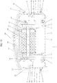
- the pump assembly comprises: a housing having a distal end and a proximal end, the housing comprising: an expandable base comprising a first base section and a second base section, wherein the first base section is in sliding engagement with the second base section such that the first base section and the second base section are slidably movable relative to each other between a compacted position and an expanded position, wherein the base in the expanded position is adapted to seat a chamber body having a plunger, wherein the chamber body defines a bore and an outlet, and the plunger is slidably disposed within the bore and wherein a distal end of the base is configured to receive the outlet of the chamber body; an expandable cover comprising a first cover section and a second cover section, wherein the first cover section is in sliding engagement with the second cover section, and wherein the cover is pivotally connected to the base at a position allowing the cover to open and close, and such that slidably moving the second base section relative to the first base section moves together the second cover section relative to the
- the first linkage is rigid to translate the movement of the cover to the movement of the puller, particularly when there is resistance from the plunger disposed in the chamber body and the leverage of the cover is used to move the puller further distally.
- a second linkage which can be rigid, is present and functions together with the first linkage to efficiently couple the movement of the cover to the movement of the puller.
- a base guide system disposed on the first base section or the second base section is used for guiding the first base section and second base section slidably movably between the compacted position and the expanded position.
- a base stop on the first base section or the second base section prevents the first base section and the second base section from separating when the first base section and the second base section are in the expanded position.
- a cover guide system disposed on the first cover section or the second cover section is used for guiding the first cover section and the second cover section slidably movably between the compacted position and the expanded position.
- a cover stop on the first cover section or second cover section prevents the first cover section and the second cover section from separating when the first cover section and the second cover section are in the expanded position.
- the pump assembly further comprises a collar slidably engaged on the base for centering and/or holding the chamber body in the housing.
- a collar stop for preventing movement of the collar distally at a defined position is used in the pump assembly.
- the pump assembly For slidably mounting the puller, pusher, and/or the collar to the base, the pump assembly comprises one or more track systems on the base to which the puller, pusher, and collar can be slidably mounted.
- the track system is present on the second base section.
- Each of the puller, pusher, and collar can have a corresponding puller guide element, pusher guide element, and collar guide element, respectively, for slidably mounting on the one or more track systems.
- the spring connected to the puller and the pusher comprises a tape spring, in particular a negator tape spring which can generate a substantially constant force on the head of the plunger when the puller is slidably moved distally, such as by lowering the cover with linkages pivotally connecting the cover to the puller.
- the cover is pivotally connected to the base by a hinge.
- the pump assembly can further comprise a damper to dampen the opening motion of the cover.
- the pump assembly can also include one or more of: a latch assembly or lock assembly for keeping the cover in the closed position on the base; a luer locator on the distal end of the first base section for holding or locking the outlet of the chamber body on to the housing; a rejector for rejecting a non-fitting chamber body seated in the base; and a progress window for viewing the chamber body when the cover is closed.
- the pump assembly is used with a syringe in an infusion system for administering a therapeutic fluid.
- the infusion system or related kits can comprise a pump assembly described herein.
- the infusion system or related kits can include in addition to the pump assembly, one or more of: a syringe dimensioned to seat in the pump assembly; a luer connector or disc luer connector for connecting the syringe to components of the infusion system; a tubing set, in particular an infusion tubing set, such as for connecting a injection needle to the syringe; a flow controller for controlling the flow of therapeutic fluid for administration; and an injection needle set for administering the therapeutic fluid into a patient's body.
- a pump assembly for dispensing liquids, e.g. therapeutic agents.
- the term “longitudinal” refers to the proximal-distal axis.
- proximal and distal for elements which can pivot away from the base, such as a cover attached to the base, the terms proximal and distal are made in reference to the closed state of the pump assembly described herein.
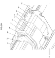
- the pump assembly comprises a housing having a distal end and a proximal end, the housing comprising a base and a cover, where the cover is pivotally connected to the base towards the proximal end so that the cover can be raised and lowered from the base, and the base is adapted to receive a chamber body having a plunger.
- the chamber body defines an outlet and a bore or lumen for receiving the plunger, and the plunger is slidingly disposed in the bore or lumen such that pushing the plunger forces out the contents of the chamber through the outlet.
- the chamber body has an opening at one end of the bore or lumen for receiving the plunger, where the opening can have a surface or flange, also referred to as an end piece, which extends out laterally away from the chamber body and is configured for holding the chamber body when pushing the plunger.
- the pump assembly further comprises: a pusher, which is slidingly engaged on the base and dimensioned to contact the head of the plunger; a puller which is slidingly engaged on the base and linked to the cover such that raising the cover moves the puller proximally and lowering the cover slidingly moves the puller distally in the base; and a spring, which is connected at a first part of the spring to the puller and at a second part of the spring to the pusher such that moving the puller distally by lowering the cover causes the pusher to slidingly move distally through the connected spring, and contact and exert force on the head of the plunger when the chamber body having the plunger is seated on the base.
- the cover linked to the puller acts as a lever to generate force to move the puller distally and generate tension in the spring, particularly when the pusher is engaged on the head of a plunger.
- use of a negator spring allows generation of substantially constant force on the pusher to provide a constant pressure pump for safe administration of therapeutic fluids.
- a constant pressure pump generates a safe, limited constant pressure, which results in improved safety for the patient.
- a constant pressure pump used in an infusion system can begin and maintain the flow rate but when a restriction occurs within the patient, the resulting back-pressure in the system results in an automatic and immediate reduction in the flow rate because the infusion system with a constant pressure pump operates in an equilibrium based on the back pressure and the flow rate.
- the pump assembly comprises: an expandable base having a proximal end and a distal end, the base comprising: a first base section and a second base section, wherein the first base section is in sliding engagement with the second base section such that the first base section and the second base section are slidably movable relative to each other between a compacted position and an expanded position, wherein the base in the expanded position is adapted to seat a chamber body having a plunger, wherein the chamber body defines a bore and an outlet, and the plunger is slidably disposed within the bore; a pusher in sliding engagement with the base, wherein the pusher is dimensioned to contact the head of the plunger; a puller in sliding engagement with the base; and a spring comprising a first portion and a second portion, wherein the first portion is connected to the puller and the second portion is connected to the pusher, wherein slidably moving the puller distally causes the pusher to contact and exert force on the head of the plunger when
- the pump assembly is a syringe pump assembly, where the chamber body comprises a syringe barrel and the plunger a syringe plunger, and the base in the expanded position is adapted to seat a syringe having an extended, e.g., fully extended, syringe plunger.
- the puller assembly can be moved distally by various configurations of the pump assembly.
- the puller can be manually pulled in the distal direction and a catch can be used to hold the puller in its distal position.
- the catch can be, for example, a hook which holds the puller in the distal position.
- a ratchet configured into the pump assembly can be employed to move the puller distally.
- the pump may or may not comprise a cover.
- the movement of the puller slidably engaged on the base is linked to a cover attached to the base such that lowering the cover moves the puller distally, while raising the cover moves the puller proximally in the base.
- the cover comprises an expandable cover which is dimensioned to cover the expandable base as the base slidably moves between the compacted and expanded positions.
- the pump assembly comprises: a housing having a distal end and a proximal end, the housing comprising: (a) an expandable base comprising a first base section and a second base section, wherein the first base section is in sliding engagement with the second base section such that the first base section and the second base section are slidably movable relative to each other between a compacted position and an expanded position, wherein the base in the expanded position is adapted to seat a chamber body having a plunger, wherein the chamber body defines a bore and an outlet, and the plunger is slidably disposed within the bore; and (b) an expandable cover comprising a first cover section and a second cover section, wherein the first cover section is in sliding engagement with the second cover section, and wherein the cover is pivotally connected to the base at a position allowing the cover to open and close, and such that slidably moving the second base section relative to the first base section moves together the second cover section relative to the first cover section when the cover is in the closed
- the cover can have a peripheral flange or lip for receiving the base in the closed position.
- the first cover section has a peripheral flange or lip adapted to receive with the first base section of the base.
- the second cover section has a peripheral flange or lip adapted to receive the second base section of the base.
- the first linkage is pivotally connected by a first pivot point hinge to the cover at a first end of the first linkage and pivotally connected by a second pivot point hinge to the puller at a second end of the first linkage.
- the first linkage is sufficiently rigid to efficiently translate the movement of the cover to the movement of the puller.
- the first linkage is bent at an angle towards the pusher on the housing.
- the first linkage is bent at a defined angle to form a bent-linkage.
- the bent angle is an obtuse angle.
- the point of the bend in the bent linkage is offset from the center of the linkage and proximal to the puller to provide a bent linkage with at least two sections, where the first section is shorter than the second section.
- the first section, the shorter section is pivotally attached to the puller while the second section, the longer section, is pivotally attached to the cover.
- the attachment point on the cover to the linkage is such that the linkage is within the housing when the cover is in the closed position.
- the syringe pump assembly further comprises a second linkage pivotally coupling the cover to the puller, wherein the pivots of the second linkage are located such that the second linkage together with the first linkage moves the puller towards the distal end when the cover is lowered and the second linkage together with the first linkage moves the puller towards the proximal end when the cover is raised.
- the second linkage is pivotally connected by a third pivot point hinge to the cover at a first end of the second linkage and pivotally connected by a fourth pivot point hinge to the puller at a second end of the second linkage.
- the second linkage is sufficiently rigid to efficiently translate the movement of the cover to the movement of the puller.
- the second linkage is bent at an angle towards the pusher on the housing.
- the second linkage is bent at a defined angle to form a bent-linkage.
- the bent angle of the second linkage is an obtuse angle.
- the point of the bend in the bent linkage is offset from the center of the second linkage and proximal to the puller to provide a bent linkage with at least two sections, where the first section is shorter than the second section. The first section, the shorter section, is pivotally attached to the puller while the second section, the longer section, is pivotally attached to the cover.
- the attachment point on the cover to the second linkage is such that the linkage is within the housing when the cover is in the closed position.
- the bend angle of the first linkage is substantially same as the bend angle of the second linkage.
- the first linkage and the second linkage are substantially the same length, and in particular, the position of the bend is substantially the same on the first linkage and the second linkage such that the first section of the first linkage is substantially the same length as the first section of the second linkage, and the second section of the first linkage is substantially the same length as the second section of the second linkage.
- the position or location on the cover for the pivotal attachment of the first linkage to the cover and the position on the cover for the pivotal attachment of the second linkage are at substantially equal distance from the proximal end.
- the position on the cover for the pivotal attachment of the first linkage from the side edge of the cover nearest the first linkage and the position on the cover for pivotal attachment of the second linkage from the side edge of the cover nearest to the second linkage are also substantially the same distance.
- first linkage and the second linkage can be linear longitudinally, or alternatively, the first linkage and the second linkage can be bent along the longitudinal axis, for example to accommodate differences between the spaced apart distances for the pivotal attachment points of the first linkage and second linkage to the cover and the spaced apart distance of the pivotal attachment points of the first linkage and second linkage to the puller.
- first linkage has an offset bend inward and the second linkage has a corresponding offset bend inward to accommodate a shorter spaced apart distance of the pivotal attachment points of the first linkage and second linkage to the puller as compared to the spaced apart distance of the pivotal attachment points of the first linkage and second linkage to the cover.
- the first linkage has an offset bend outward and the second linkage has a corresponding offset bend outward to accommodate a shorter spaced apart distance of the pivotal attachment points of the first linkage and the second linkage to the cover relative to the spaced apart distance of the pivotal attachment points of the first linkage and the second linkage to the puller.
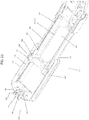
- the pump assembly has an expandable base, where the base comprises a first base section and a second base section, and the first base section and the second base section are in sliding engagement.
- the first base section comprises a first pair of opposing base sidewalls, where one wall is on one side edge of the first base section and the other wall is on the other side edge of the first base section; a distal wall on the first base section; and an open end opposite the distal wall.
- the distal wall of the first base section has a recess, partially circular recess such as an open collar, to provide an opening for the outlet of the chamber body, and in certain embodiments, for a luer locator, as further described herein.
- the second base section comprises a second pair of opposing base sidewalls, where one wall is on one side edge of the second base section and the other wall is on the other side edge of the second base section; a proximal wall on the second base section, which in certain embodiments includes the hinge assembly, as further described below; and an open end opposite the proximal wall.
- the open end of the first base section faces the open end of the second base section when the first base section and the second base section are in sliding engagement.
- the first base section and the second base section are in telescoping relation to each other.
- the second base section is adapted to fit into the first base section such that the first base section and the second base section are slidingly movable relative to each other.
- a base guide system is disposed on the first base section or the second base section for guiding the first base section and the second base section slidably movably relative to each other between the compacted position and the expanded position.
- the base guide system prevents the vertical separation of the first base section from the second base section when the first base section and the second base section are slidingly engaged.
- the base guide system also provides sufficient rigidity to withstand the vertical stresses imposed on the slidingly engaged first base section and the second base section, for example, when a chamber body having a plunger, e.g., a syringe, is seated on the base and the cover closed or lowered to apply force on the head of the plunger.
- the base guide system comprises a base guide bar or arm disposed longitudinally on the first base section or the second base section, and a corresponding complementary base guide slot on the second base section or the first base section, respectively, wherein the base guide bar or arm mates slidably into the corresponding complementary base guide slot on the second base section or first base section.
- the base guide bar or arm is an elongated plate or stay
- the complementary base guide slot is an elongate rectangular recess dimensioned to receive the elongated plate or stay in slidable engagement.
- the guide bar or arm is a rod, such as a cylindrical rod
- the complementary base guide slot is a bore or lumen dimensioned to receive the rod in slidable engagement.
- the base guide system comprises a base guide rail disposed longitudinally on the first base section or second base section, and a complementary base guide track on the second base section or first base section, respectively, wherein the base guide rail mates slidably into the corresponding complementary base guide track on the second base section or the first base section.
- the base guide system comprises a base guide rail having a T shaped cross section disposed longitudinally on the first base section or second base section, and a corresponding complementary base guide track comprising a base linear groove or slot having a T shaped cross sectional space on the second base section or first base section, respectively, wherein the base guide rail mates slidably into the corresponding base guide track comprising the base linear groove or slot on the second base section or first base section.
- the base guide system comprises 2 or more base guide rails, each base guide rail having a T shaped cross section on the first base section or the second base section, and a corresponding complementary base guide track comprising 2 or more base linear groove or slots, each groove or slot having a T shaped cross sectional space on the second base section or the first base section, wherein the base guide rail mates slidably into the corresponding base guide track.
- the base guide system comprises a base guide rail having an L shaped cross section, and a corresponding base linear groove or slot having an L shaped cross sectional space on the second base section or first base section, respectively, wherein the base guide rail mates slidably into the corresponding complementary base linear groove or slot on the second base section or the first base section.
- the base guide system comprises 2 or more base guide rails having L shaped cross section on the first base section or the second base section, and a corresponding complementary base guide track comprising 2 or more linear groove or slots, each groove or slot having an L shaped cross sectional space on the second base section or the first base section, wherein the base guide rail mates slidably into the corresponding base guide track.
- the base guide system comprises a base linear rail along the length of each side wall of the first pair of opposing side walls of the first base section or each side wall of the second pair of opposing side walls of the second base section, and a corresponding base linear track comprising a linear groove or channel, wherein the base linear rail mates slidably into the corresponding complementary linear groove or channel on the second base section or first base section.
- the base guide system comprises 2 or more linear rails along the length of each side wall of the first pair of side walls of the first section or each side wall of the second pair of side walls of the second base section, and a corresponding complementary base linear track comprising 2 or more linear grooves, wherein the base linear rail mates slidably into the corresponding complementary base guide track.
- the base guide system comprises a base rim along the length of each side wall of the first pair of opposing side walls of the first base section or each side wall of the second pair of opposing side walls of the second base section, and a corresponding groove or channel complementary to the rim on the second base section or first base section, respectively, wherein the base rim mates slidably into a corresponding complementary groove or channel on the second base section or first base section.
- the base guide system comprises a base edge flange along the length of each side wall of the pair of opposing side walls of the first base section or each wall of the second pair of opposing side walls of the second base section, wherein the base edge flange mates slidably the corresponding side wall of the second pair of opposing side walls on the second base section or the side wall of the first pair of opposing side walls of the first base section.
- the base edge flange is L shaped and mates slidably with the corresponding side wall of the second pair of opposing side walls of the second base section or the corresponding side wall of the first pair of opposing side walls of the first base section.
- the base edge flange curves downward to form a C, J or U shaped curl and mates slidably with the corresponding side wall of the second pair of opposing side walls of the second base section or the corresponding side wall of the first pair of opposing side walls of the first base section.
- the base guide system comprises a pair of side double walls on the first base section or second base section, wherein each double wall defines a space in between, and wherein each side wall of the second pair of sidewalls on the second base section or each side wall of the first pair of sidewalls on the first base section slidingly engage the corresponding double wall through the space in between the double wall.
- the base has a single base guide system, or in other embodiments at least two or more base guide systems.
- the base has a first guide system and a second guide system.
- the first base guide system is the same form of guide system as the second base guide system.
- the first base guide system is a different form of a guide system than the second guide system.
- the base further comprises a base stop.
- the base stop is present on the first base section or the second base section for preventing the first base section and the second base section from separating when the first base section and the second base section are slidably moved from the compacted position to the expanded position.
- the base stop can comprise a detent element on the first base section or the second base section and a corresponding counter detent element on the second base section or first base section, respectively.
- the detent element can be a screw, protrusion, nub, or flange, and the counter detent element can comprise a complementary recess, depression, or hole which receives the detent element.
- the counter detent element is a spring tab present in the corresponding second base section or first base section.
- the detent element is present on the first base section or the second base section, and the counter detent element comprises a corresponding detent groove on the second base section or first base section respectively, wherein the ends of the detent groove catch the detent element to prevent the first base section and the second base section from separating.
- the base stop is present or integrated on the base guide system.
- the guide system comprises a base guide rod, such as a cylindrical rod and the base guide slot is a complementary bore or lumen which receives the base guide rod
- the base stop can be a flange or a clamp on the end of the rod to prevent the rod from sliding off of the complementary base guide slot.
- the detent element can be on the one or each side wall of the pair of side walls on the first base section or the second base section, and a corresponding base stop is present on the second base section or the first base section, respectively.
- an inwardly protruding end piece is present on the end (e.g., distal or proximal end) of one or each of the side walls of the pair of side walls on the first base section or the second base section.
- a protruding base stop which can contact the inwardly protruding end piece is present on the second base section or first base section, respectively, for example, near the side wall with the protruding end piece.
- the pump assembly has an expandable cover, where the cover comprises a first cover section and a second cover section, and the first cover section and the second cover section are in sliding engagement.
- the first cover section comprises a first pair of opposing cover sidewalls, where one wall is on one side edge of the first cover section and the other wall is on the other side edge of the first cover section; a distal wall on the first cover section; and an open end opposite the distal wall.
- the distal wall of the first cover section has a recess, a partially circular recess such as an open collar, which opposes a recess or open collar on the distal wall of the first base section to form the opening for the outlet of the chamber body when the cover is in the closed position.
- the second cover section comprises a second pair of opposing cover sidewalls, where one wall is on one side edge of the second cover section and the other wall is on the other side edge of the second cover section; a proximal wall on the second cover section, which in certain embodiments includes the hinge assembly, as further describe below; and an open end opposite the proximal wall.
- the open end of the first cover section faces the open end of the second cover section when the first cover section and the second cover section are in sliding engagement.
- first cover section and the second cover section are in telescoping relation to each other.
- the second cover section is adapted to fit into the first cover section such that the first cover section and the second cover section are slidingly movable relative to each other.
- a cover guide system is disposed on the first cover section or the second cover section for guiding the first cover section and the second cover section slidably movably between the compacted position and the expanded position.
- the cover guide system prevents the vertical separation of the first cover section from the second cover section when the first cover section and the second cover section are in sliding engagement.
- the cover guide system also provides sufficient rigidity to withstand the vertical stresses imposed on the slidingly engaged first cover section and the second cover section, for example, when the cover is lowered to move the puller distally and apply force to the head of a plunger on a chamber body, e.g., a syringe seated on the base.
- the cover guide system comprises a cover guide bar or arm disposed longitudinally on the first cover section or the second cover section, and a corresponding complementary cover guide slot on the second cover section or the first cover section, respectively, wherein the cover guide bar or arm mates slidably into the corresponding complementary cover guide slot on the second cover section or first cover section.
- the cover guide bar or arm is an elongated plate or stay
- the complementary cover guide slot is an elongate rectangular recess dimensioned to receive the elongated plate or stay in sliding engagement.
- the guide bar or arm is a rod, such as a cylindrical rod
- the complementary cover guide slot is a bore or lumen dimensioned to receive the rod in sliding engagement.
- the cover guide system comprises a cover guide rail disposed longitudinally on the first cover section or second cover section, and a complementary cover guide track on the second cover section or first cover section, respectively, wherein the cover guide rail mates slidably into the corresponding complementary cover guide track on the second cover section or the first cover section.
- the cover guide system comprises a cover guide rail having a T shaped cross section disposed longitudinally on the first cover section or second cover section, and a corresponding complementary cover guide track comprising a cover linear groove or slot having a T shaped cross sectional space on the second cover section or first cover section respectively, wherein the cover guide rail mates slidably into the corresponding cover guide track comprising the cover linear groove or slot on the second cover section or first cover section.
- the cover guide system comprises 2 or more cover guide rails, each cover guide rail having T shaped cross section on the first cover section or the second cover section, and a corresponding complementary cover guide track comprising 2 or more cover linear groove or slots, each groove or slot having a T shaped cross sectional space on the second cover section or the first cover section, wherein the cover guide rail mates slidably into the corresponding cover guide track.
- the cover guide system comprises a cover guide rail having an L shaped cross section disposed longitudinally on the first cover section or the second cover section, and a corresponding cover linear groove or slot having an L shaped cross sectional space on the second cover section or first cover section, respectively, wherein the cover guide rail mates slidably into the corresponding complementary cover linear groove or slot on the second cover section or the first cover section.
- the cover guide system comprises 2 or more cover guide rails having L shaped cross section on the first cover section or the second cover section, and a corresponding complementary cover guide track comprising 2 or more linear groove or slots, each groove or slot having an L shaped cross sectional space on the second cover section or the first cover section, wherein the cover guide rail mates slidably into the corresponding cover guide track.
- the cover guide system comprises a cover linear rail along the length of each side wall of the first pair of opposing side walls of the first cover section or each side wall of the second pair of opposing side walls of the second cover section, and a corresponding cover linear track comprising a linear groove or channel, wherein the cover linear rail mates slidably into the corresponding complementary linear groove or channel on the second cover section or first cover section.
- the cover guide system comprises 2 or more linear rails along the length of each side wall of the first pair of opposing side walls of the first cover section or each side wall of the second pair of opposing side walls of the second cover section, and a corresponding complementary cover linear track comprising 2 or more linear grooves, where the cover linear rail mates slidably into the corresponding complementary cover guide track.
- the cover guide system comprises a cover rim along the length of each side wall of the first pair of opposing side walls of the first cover section or each side wall of the second pair of opposing side walls of the second cover section, and a corresponding groove or channel complementary to the rim on the second cover section or first cover section, respectively, wherein the cover rim mates slidably into a corresponding complementary groove or channel on the second cover section or first cover section.
- the cover guide system comprises a cover edge flange along the length of each side wall of the pair of opposing side walls of the first cover section or each wall of the second pair of opposing side walls of the second cover section, wherein the cover edge flange mates slidably the corresponding side wall of the second pair of opposing side walls on the second cover section or the side wall of the first pair of opposing side walls of the first cover section.
- the cover edge flange is L shaped and mates slidably with the corresponding side wall of the second pair of side walls of the second cover section or the corresponding side wall of the first pair of side walls of the first cover section.
- the cover edge flange curves downward to form a C, J or U shaped curl and mates slidably with the corresponding side wall of the second pair of side walls of the second cover section or the corresponding side wall of the first pair of side walls of the first cover section.
- the cover guide system comprises a pair of side double walls on the first cover section or second cover section, wherein each double wall defines a space in between, and wherein each side wall of the second pair of sidewalls on the second cover section or each side wall of the first pair of sidewalls on the first cover section slidingly engages the corresponding double wall through the space in between the double wall.
- the cover has a single guide system, or in other embodiments at least two or more guide systems.
- the cover has a first cover guide system and a second cover guide system.
- the first cover guide system is the same form of guide system as the second cover guide system.
- the first cover guide system is a different form of a guide system than the second guide system.
- the cover further comprises a cover stop.
- the cover stop is present on the first cover section or the second cover section for preventing the first cover section and the second cover section from separating when the first cover section and the second cover section are slidably moved from the compacted position to the expanded position.
- the cover stop can comprise a detent element on the first cover section or the second cover section and a corresponding counter detent element on the second cover section or first cover section, respectively.
- the detent element can be a screw, protrusion, nub, or flange, and the counter detent element can comprise a complementary recess, depression, or hole which receives the detent element.
- the counter detent element is a spring tab present in the corresponding second cover section or first cover section.
- the detent element is present on the first cover section or the second cover section, and the counter detent element comprises a corresponding detent groove on the second cover section or first cover section respectively, wherein the ends of the detent groove catch the detent element to prevent the first cover section and the second cover section from separating.
- the cover stop is present or integrated on the cover guide system.
- the guide system comprises a cover guide rod, such as a cylindrical rod and the cover guide slot is a complementary bore or lumen which receives cover guide rod
- the cover stop can be a flange or a clamp on the end of the rod to prevent the rod from sliding off of the complementary cover guide slot.
- the detent element can be on the one or each side wall of the pair of side walls on the first cover section or the second cover section, and a corresponding cover stop is present on the second cover section or the first cover section, respectively.
- an inwardly protruding end piece is present on the end (e.g., distal or proximal end) of one or each of the side walls of the pair of side walls on the first cover section or the second cover section.
- a protruding cover stop which can contact the inwardly protruding end piece is present on the second cover section or first cover section, respectively, near the side wall with the protruding end piece.
- the cover also has a progress window for viewing the chamber body when the cover is closed.
- the progress window at least allows viewing of the chamber body, for example a syringe barrel, near the outlet of the chamber body.
- the progress window is present on the first cover section.
- the progress window can be sufficiently wide to see the chamber body.
- the progress window is a slit, which allows for viewing of the amount of fluid remaining in the chamber body, such as in a syringe barrel.
- the progress window can be open, or in some embodiments, the progress window can comprise a transparent material, such as glass or clear plastic.
- the pump assembly further comprises one or more track systems on the base for slidably mounting: the puller and/or the pusher, or a collar for centering or holding the chamber body, as further described below.
- the track system is disposed to allow slidable movement longitudinally (i.e., proximal-distal) of the puller, pusher and collar.
- at least one track system is present on the first base section.
- the at least one track system is integral with the first base section; that is the track system is part of the first base section when formed.
- the at least one track system is mounted on the first base section; that is the track system is made separately and attached to the first base section.
- the at least one track system is present on the first pair of opposing side walls of the first base section.
- at least two track systems are present on the first pair of opposing side walls of the first base section.
- At least one track system is present on the second base section. In some embodiments, the at least one track system is integral with the second base section. That is, the track system is part of the second base section when formed. In some embodiments, the at least one track system is mounted on the second base section; that is the track system is made separately and attached to the second base section. In some embodiments, the at least one track system is present on the second pair of opposing side walls of the second base section. In other embodiments, at least two track systems are present on the second pair of opposing side walls of the second base section.
- a single track system is used to slidably mount the pusher, puller and collar.
- two different track systems are used to slidably mount the pusher, pusher and collar.
- each of the puller, the pusher and the collar are slidably mounted on different track systems.
- the puller further comprises a puller guide element which slidably mounts the puller to at least one track system.
- the pusher further comprises a pusher guide element which slidably mounts the pusher to at least one track system.
- the collar further comprises a collar guide element which slidably mounts the collar to at least one track system.
- each track system comprises one or more track guides for slidably mounting the puller, pusher and/or collar.
- the track guide slidably engages the puller guide element, the pusher guide element, and/or the collar guide element.
- the track guide can be integral with the base, or mounted on the base.
- a flat rectangular plate having track guide can be attached to the floor of the first base section or the second base section.
- the track guides can be disposed on the surface of the plate or on the side edges of the plate.
- track guides can be formed on the first base section or second base section, or attached to the floor of the first base section or second base section.
- the track guide comprises a track guide rail, wherein the puller guide element, the pusher guide element and/or the collar guide element mounts slidably on the track guide rail.
- the track system comprises a single track guide. In other embodiments, the track system comprises two or more track guides.
- the track guide rail comprises a track guide bar, wherein the puller guide element, the pusher guide element and/or the collar guide element mounts slidably on the track guide bar.
- the track guide bar is an elongated rectangular sheet or bar on the first base section or second base section.
- the guide element on the puller, pusher and/or collar can be a sleeve with a rectangular cross sectional space or a C shaped guide element which slidably mounts on the rectangular sheet or bar.
- the track guide is a rod, such as a cylindrical rod on the first base section or the second base section, and the guide elements on the puller, pusher, and or collar can have a cylindrical bore which slidably mounts on the cylindrical rod.
- the track guide rail has a T shaped cross section, wherein the puller, puller, and/or collar guide element slidably mates complementary to the T shaped guide rail, for example a guide element with a T shaped cross sectional space or a guide element with a C shaped cross sectional space and wraps around the top of the T shape guide rail.
- the track guide can comprise a linear groove or slot with a T shaped cross sectional space, wherein the puller, pusher, and/or collar guide element has a cross sectional T shape which slidably mates into the T shaped groove or slot.
- the track guide rail has an L shaped cross section, wherein the puller, pusher, and/or collar guide element slidably mates complementary to the L shaped guide rail.
- the track guide can comprise a linear groove or slot with an L shaped cross sectional space, wherein the puller, pusher, and/or collar guide element has a cross sectional L shape which slidably mates into the L shaped groove or slot.
- the track system can have one track guide or multiple track guides.
- the track system comprises at least two track guides, e.g., a first track guide and a second track guide.
- the first track guide comprises a first linear rail facing inward and extending longitudinally along the second base section
- the second track guide comprises a second linear rail facing inward and extending longitudinally along the second base section, wherein the second linear rail is on the opposing side and faces the first linear rail, and wherein the lower wall of the first linear rail and the floor of the second base section defines a first channel and the lower wall of the second linear rail and the floor of the second base section defines a second channel, wherein the first channel and the second channel face inward and towards each other.
- the first linear rail is at one inside side edge of the second base section and the second linear rail is at the other inside side edge of the second base section.
- the puller guide element, the pusher guide element, and/or the collar guide element slidably mount complementary to the first and second linear guide rails.
- the puller guide element, the pusher guide element, and/or the collar guide element slidably mount on the first and second channels formed by the first and second linear guide rails, respectively.
- the first track guide comprises a first channel or first groove facing inward and extending longitudinally along the second base section
- the second track guide comprises a second channel or second groove facing inward and extending longitudinally along the second base section, wherein the first channel and second channel are parallel and face each other.
- the first channel is at one inside edge of the second base section and the second channel is at the other inside edge of the second base section.
- the first channel is present on one of the side walls of the pair of opposing side walls of the second base section
- the second channel is present on the other side wall of the pair of opposing side walls of the second base section.
- the puller guide element, the pusher guide element, and/or collar guide element slidably mount in the inward facing channels.
- the first track guide comprises a first flange extending longitudinally along one inside side edge of the second base section and the second track guide comprises a second flange extending longitudinally along the other inside side edge of the second base section, wherein the puller guide element, the pusher guide element, and/or collar guide element mates slidably to the first and second flanges.
- Various types of flanges can be used for the track system.
- the first and second flanges form a C, J or U shaped curl inward and mates slidably with the puller guide element, the pusher guide element, and/or the collar guide element.
- the flange is an L shape flange and mates slidably with the puller guide element, the pusher guide element, and/or the collar guide element.
- multiple track systems using the same type of track guides or using different types of track guides can be used.
- various types of track systems using different types of track guides can be combined to slidably engage the puller, pusher and/or collar to the base of the pump assembly.
- multiple sets of channels disposed on the second base section, including the pair of opposing side walls of the second base section, can be adapted to slidably engage the puller, pusher and collar to the base.
- the pump assembly comprises a first track system and a second track system
- the first track system comprises a first channel and a second channel
- the first channel faces inward and extends longitudinally along one inside edge of the second base section
- the second channel faces inward and extends longitudinally along the other inside edge of the second base section, wherein the first channel and second channel are parallel and face each other
- the second track system comprises a third channel and a fourth channel, wherein the third channel faces inward and extends longitudinally along the inside face of one side wall of the pair of side walls of the second base section, and the fourth channel faces inward and extends longitudinally along the inside face of the other side wall of the pair of side walls of the second base section, wherein the third channel and the fourth channel are parallel and face each other.
- the puller and the pusher are slidably engaged to the first track system, while the collar is slidably engaged to the second track system. In another specific embodiment, the puller and pusher are slidably engaged to the second track system, while the collar is slidably engaged to the first track system.
- the pump assembly comprises a first track system and a second track system
- the first track system comprises a first channel and a second channel, where the first channel faces inward and extends longitudinally along one inside edge of the second base section, and the second channel faces inward and extends longitudinally along the other inside edge of the second base section, wherein the first channel and second channel are parallel and face each other
- the second track system comprises a first linear groove or slot with an L shaped cross sectional space extending longitudinally along the inside face of one side wall of the pair of opposing side walls of the second base section, and a second linear groove or slot with an L shaped cross sectional space extending longitudinally along the inside face of the other side wall of the pair of opposing side walls of the second base section, wherein the first linear groove or slot and the second linear groove or slot face each other.
- the puller and the pusher are slidably engaged to the first track system, while the collar is slidably engaged to the second track system. In other embodiments, the puller and pusher are slidably engaged on the second track system, while the collar is slidably engaged on the first track system.
- the pusher is slidably engaged on the base and dimensioned to contact the head of the plunger.
- the pusher can be any form sufficient for the purposes in the pump assembly.
- the puller can comprise a pusher sled or plate, wherein the sled or plate slidably engages the track system through the pusher guide element, as further described herein.
- the pusher can have wheels, rollers, or bearings, particularly micro wheels, micro rollers or micro bearings, attached to the pusher, such as to the bottom of the pusher, to reduce the friction on the pusher at is slidably moves in the base.
- the plunger head contacting portion of the pusher can be adapted to contact any type of plunger head, including plunger heads of different shapes and surfaces.
- the plunger head contacting portion can be substantially rectangular, substantially circular, substantially elliptical, substantially D, or substantially C cross sectional shape, and be solid or have a recessed space for contacting the plunger head.
- the recessed space can have internal supporting members, such as ribs or internal walls (e.g., angled or vertical).
- the plunger head contacting portion can have a recessed space or configured in any three dimensional shape to accept the head of the plunger.
- the plunger head contacting portion can be attached to the other elements of the pusher, such as the spring housing, in other embodiments, the plunger head contacting portion can be separate and be slidably engaged on the track system separately from the other portion of the pusher.
- the pusher has a latch on the plunger head contacting portion of the pusher to latch onto the plunger head when the pusher contacts the plunger head. The latch can be engaged onto the plunger head while the chamber body having the plunger is empty by closing the cover to move the puller and the pusher distally until the pusher contacts the plunger head.
- the chamber body By having a tubing attached to the outlet of the chamber body and connected to a reservoir of fluid, the chamber body can be filled in the pump assembly by opening and raising the cover to move the puller and pusher proximally, which withdraws the plunger from the chamber body and allows the chamber in the chamber body to fill with fluid from the fluid reservoir.
- the latch can be spring loaded latches that clip onto the head of the plunger when the pusher comes in contact with the plunger head.
- the pusher also has a plunger head centering structure which guides the plunger head to the plunger head contacting portion of the pusher.
- the plunger head centering structure of the pusher can comprise a conical structure, with the wider opening of the conical centering structure facing distally, towards the head of plunger.
- the plunger centering structure comprises centering wings which curve outward from the pusher towards the distal end, thereby guiding the plunger head to the plunger head contacting portion.
- Other various embodiments of the plunger head centering structure will be apparent to the skilled artisan.
- the pusher further comprises a pusher guide element, wherein the pusher guide element slidably mounts the pusher on the track system, in particular the pusher guide element mates slidably with the one or more of the track guides of the track system.
- the pusher guide element comprises a pusher sled or plate which mates slidably with the first track guide and the second track guide, such as channels disposed on the inside side edges of the second base section.
- the pusher further comprises a pusher spring housing and a pusher spool, wherein the pusher spool is mounted in the pusher spring housing, and the spring, particularly a tape spring, is coiled around the pusher spool.
- the pusher spool comprises a drum, where the spring, in particular a tape or ribbon spring, is coiled around the drum.
- the drum can be mounted on a drum shaft present on the spring housing.
- the pusher spool is a shaft, where the spring is coiled around the shaft.
- the spring is attached to the pusher without being coiled around a pusher spool.
- the puller is slidably engaged on the base and used to affect tension in the spring by slidably moving the puller between the proximal and distal ends.
- the puller is slidably mounted distal to the pusher.
- the puller can be any form sufficient for the purposes in the pump assembly.
- the puller can comprise a puller block or puller sled, wherein the block or sled slidably engages the track system through the puller guide element.
- the first end portion of the spring is attached to the puller and the puller mates slidably with track guide of the track system.
- the puller mates slidably with the first track guide and the second track guide of the track system, for example channels on the inside side edges of the second base section.
- the puller can have wheels, rollers, or bearings, particularly micro wheels, micro rollers, or micro bearings, attached to the puller, such as to the bottom of the puller, to reduce the friction on the puller as it slidably moves in the base.
- the puller comprises a puller spring housing and a puller spool, wherein the puller spool is mounted in the puller spring housing, and the spring is coiled around the puller spool.
- the puller spool is a drum, or in other embodiments, a shaft, where the spring, in particular a tape or ribbon spring is coiled around the drum or the shaft.
- the spring is attached to the puller without being coiled around the puller spool.
- the spring for use in the pump assembly can be any suitable spring.
- the spring as configured in the pump assembly generates a substantially constant force.
- the spring comprises a tape spring or ribbon spring.
- the spring is an extendable negator spring.
- the spring for use in the pump assembly is a single spring.
- the spring in the pump assembly comprises two or more springs. Where multiple springs are used, in some embodiments, the springs are substantially similar and generate substantially similar constant force. In other embodiments where multiple springs are used, the two or more springs are different springs, such as of different dimensions, lengths, and/or different constant force.
- the springs in particular the substantially constant force springs can be made of metal, such as stainless steel, high carbon steel, nickel chromium alloy, nickel titanium alloy, or made of non-metal composites (see, e.g., U.S. Patent No. 4,464,216 , incorporated herein by reference).
- the spring is made of shape memory alloy.
- the constant force spring is selected from a spring with about 5 to about 9 pounds of force such as about 6 to about 8 pounds of force.
- the pump may exert a pressure from about 5 psi to about 15 psi, such as about 11 psi to about 14 psi, or such as about 12 psi to about 14 psi. In certain embodiments, the pump may exert a pressure of about 5 to about 14 psi, such as about 13.5 psi.
- the spring is attached to the puller at a first portion of the spring and attached to the pusher at a second portion of the spring such that moving the puller distally with respect to the pusher creates tension in the spring when there is resistance against movement of the pusher.
- the spring is attached to the puller at a first end portion of the spring and attached to the pusher at a second end portion of the spring.
- the spring can be attached to the puller at a distal position of the puller to create tension in the spring even when the cover is fully opened position.
- the puller can be elongated and the spring attached at any point on the elongated puller, such as at the distal end, to provide variations in the tension with the pusher when the cover is fully opened.
- the spring is coiled around the pusher spool and attached to the puller at the first end portion.
- the spring is coiled around the puller spool and attached to the pusher at the second end portion. The direction of coiling when the spring is coiled around the puller spool or the pusher spool is such that moving the puller distally can introduce tension in the spring and applies force on the pusher distally.
- the spring is coiled around the puller spool and the pusher spool.
- a tape spring is attached to the puller at a first end portion, the pusher at a second end portion, and coiled around the spool on the pusher such that the tape spring produces substantially constant force on the plunger head when the coiled tape spring is unwound by moving the puller distally.
- the pump assembly further comprises a collar for centering and/or holding the chamber body seated in the base, wherein the collar is positioned on the base distal to the pusher.
- collar is adapted for centering and/holding a syringe barrel.
- the collar has a surface which is adapted to receive the end piece of the chamber body, also referred to as the finger flange, in particular the end piece or finger flange of a syringe barrel.
- the collar has a recessed space which is complementary to the end piece.
- the collar can be adapted to receive a single end piece or finger flange, or adapted to receive two or more different sized end pieces or finger flanges.
- the collar can have an outer recess dimensioned to receive a first end piece, and an inner recess dimensioned to receive a second end piece, where the second end piece is smaller than the first end piece.
- a stepped-recess can be used in a single collar to receive end pieces of varying sizes, wherein the recesses are stepped to smaller recesses from the distal to proximal direction, and wherein each recess receives an end piece differing in size from the other recesses.
- the collar can be an open collar or a closed collar. In certain embodiments, where the collar is an open collar, the collar includes a slot adapted for receiving the finger flanges of a chamber body, e.g., finger flanges of a syringe barrel.
- the collar is slidably engaged on the base. In some embodiments, the collar is slidably engaged on the first base section or the second base section, preferably the first base section. In some embodiments, the collar is slidably engaged on any of the track systems described herein. In certain embodiments, the collar is slidably engaged on a track system different from the track system to which the puller and pusher are slidably engaged. In other embodiments, the collar is slidably engaged on the same track system to which the puller and pusher are slidably engaged. As such, in certain embodiments, the collar further comprises a collar guide element, such as described for the puller and pusher guide elements, for slidably mounting the collar on the base. In other embodiments, the collar is dimensioned to fit the base and slidingly engage the base. The collar can be allowed to slide freely on the base, distally and proximally.
- a collar spring or elastic band can be used to press the collar against the end piece or finger flange of the chamber body.
- the collar spring or elastic band can be positioned distal to the collar or proximal to the collar.
- a collar spring is used.
- the collar spring comprises a compression spring positioned proximal to the collar.
- the collar spring contacts the collar at a first end of the collar spring and contacts the base at a position proximal to the collar, for example, the proximal wall of the second section of the base, at a second end of the collar spring.
- the collar spring can be mounted on a channel, for example a C shaped cross sectional channel, or in other embodiments, the collar spring can be wrapped around a collar spring guide rod, which extends longitudinally.
- the channel or guide rod used for the collar spring can be part of the track system used for slidably mounting the collar to the base.
- the pump assembly further comprises a collar stop for preventing movement of the collar distally at a defined position.
- the collar stop is made positionally adjustable.
- the collar stop is adapted to receive the chamber body, particularly a syringe, more particularly the syringe barrel.
- the collar stop is attached to the distal end of the track systems described herein.
- the collar stop is attached to the open end of the second base section. Whether the collar stop is positionally adjustable, attached to the distal end of a track system, or attached to the open end of the second base section, in certain embodiments, the collar stop can be slidably engaged on a collar stop guide rail.
- the collar stop can have a collar stop guide element, such as those described for the puller, pusher, and collar.
- the collar stop guide track or rail is disposed on the first base section.
- the collar stop engages a base stop, as described herein, to prevent separation of the first base section and the second base section in the expanded position.
- the cover is pivotally connected to the base by a hinge.
- the cover is connected to the proximal end of the base by a hinge.
- the hinge pivotally connects the second cover section to the second base section.
- a single hinge is used.
- the cover is pivotally connected to the proximal end of the base, in particular the second base section, by two or more hinges.
- the pump assembly further comprises a damper which dampens the opening motion of the cover.
- the damper can be separate from the hinge, and the damper pivotally coupled to the cover and the base.
- the damper is integrated into the mechanism of the hinge; that is, the hinge comprises a damper. Whether separate or as part of the hinge, the damper can employ various types of dampening mechanisms.
- the damper is a viscous damper, a fluid damper, or a rotary friction damper. See , e.g ., U.S. Patent No. 7,275,284 ; 6,829,807 ; 6,085,384 ; and 4,829,628 , incorporated herein by reference.
- the pump assembly includes a latch assembly or a lock assembly for keeping the cover in the closed position, particularly when a chamber body having a plunger is seated in the base and the cover lowered to move the puller distally and provide constant force on the plunger head through the puller, or keep the cover in the closed position during storage of the pump assembly.
- the latch assembly or lock assembly can be located on the side of the housing, including both sides of the housing near or at the distal end. In some embodiments, the latch assembly or lock assembly is on or near the distal end of the housing, i.e., distal end of the base and the cover, such as the distal end of the first base section and the first cover section.
- latch assemblies or lock assemblies can be used, including, among others, rotary latch, bayonet latch, draw latch (e.g., over center latches, pull draw latches, butt joint fastening latches), slide latch, magnetic latch, pin lock, bayonet lock, rotary latch loc, and the like.
- the latch system can comprises a screw, nub, mound, or protrusion, which mates with a depression, indentation or hole to resist opening of the cover.
- a nub or mound can be present on the inside face of a flange on the distal wall of the first cover section, wherein the flange overlaps the distal wall of the first base section when the cover is closed; and a depression complementary to the nub or mound is present on the outside face of the distal wall of the second cover section, wherein closing the cover engages the nub or mound on the flange on the first cover section onto the depression on the distal wall of the second cover section.
- the housing has a luer locator for receiving and/or locking the tip of the syringe onto the housing, in particular the base of the pump assembly.
- the luer locator is dimensioned to receive a luer type outlet of a syringe barrel.
- the luer locator is on the distal wall of the first base section.
- the luer locator comprises a collar on the distal wall of the first base section.
- the luer locator collar can be a partially cylindrical recess which receives a cylindrical luer lock tip of the chamber body and centers the outlet on the collar defining the luer locator.
- the distal wall of the first cover section has an open collar, which with the luer locator on the distal wall of the first base section forms the opening on the housing for the outlet of the syringe.
- the distal wall of the cover in particular the distal wall of the first cover section, has an open collar, e.g., a partially circular collar, opposing the luer locator and/or open collar of the distal wall of the first base section to form the opening for the outlet when the housing is in the closed state.
- the distal wall of the base is also adapted to receive a disc luer connector, wherein the disc luer connector is attached to the outlet of a chamber body, e.g., a syringe.
- the disc luer connector has a disc shaped flange to protect the luer connecting end from becoming contaminated during handling.
- the disc luer connector contains a filter for filtering out contaminating particulates and microbes in therapeutic fluids.
- An exemplary disc luer connector with filter is described in International application PCT/US15/16929 , incorporated herein by reference.
- the disc luer connector contacts the inside face of the distal wall, which acts to brace the disc luer connector and connected syringe when force is applied to the syringe plunger.
- the distal wall of the base has an open collar with a recessed space for receiving a disc portion of the disc luer connector.
- the distal wall has a partially circumferential flat surface on the inside face of the distal wall, around the luer locator collar, for contacting or receiving the disc luer connector.
- the pump assembly further comprises a rejector for rejecting a non-fitting chamber body.
- the rejector comprises one or more rejector ramps at the distal wall adapted to receive the syringe outlet.
- the rejector ramps are sloped upwards towards the distal wall and cause non-fitting syringes to slide out of the base when the cover is lowered and force applied to the plunger head.
- the rejection ramps can be formed of a sloped plate, or sloped ribs extending downward from the distal wall to the base from the distal to proximal direction, or alternatively, angled downward from the distal end to the proximal end.
- the rejector ramps comprise spaced apart angled ribs or spaced apart sloping walls extending downward from the distal wall, and is sufficiently spaced apart to allow seating of syringe barrels with defined diameters.
- the rejector can be configured to reject different chamber bodies, and a single pump assembly can have different rejectors for rejection of different chamber bodies.
- the pump assembly further comprises a means for hanging or holding the pump assembly.
- the pump assembly has a strap, cord or chain for hanging or holding the pump assembly.
- the strap is a shoulder harness, or a strap that wraps around the body.
- the strap is a loop strap.
- the pump assembly has a clip for clipping the pump assembly onto a support structure.
- the clip is a belt clip.
- the pump assembly is preferably lightweight yet made of durable materials, e.g., aluminum, plastic, or combinations thereof.
- the components of the pump may comprise any suitable materials such as metal or plastics or any combination thereof.
- the cover and the base of the pump comprise a metal such as aluminum, e.g., 6000 series aluminum.
- the aluminum can have a hard coating and/or anodization.
- the lower end cap and upper end caps, when present, can be made of a plastic such as an impact resistant plastic, e.g., acrylonitrile butadiene styrene (ABS).
- ABS acrylonitrile butadiene styrene
- the cover and the base are made from durable rigid plastic or impact resistant plastic, and certain other parts, such as the track guides, made from metal, such as aluminum.
- various lubricants can be used in the pump assembly to reduce friction on moving parts, such as the pusher, puller and collar.
- the pump assembly When the pump assembly is not in use, it reduces to a compact size suitable for storage and/or and/or portability.
- the housing is expanded by slidably moving the housing from the compacted position to the expanded position, the cover opened and a chamber body having a plunger, in particular a syringe barrel with a slidably disposed plunger, seated in the base.
- the puller When the cover of the pump is closed, the puller is moved distally such that the syringe plunger receives a constant force from the pusher, and the contents of the chamber are expelled through the outlet of the chamber body.
- the puller When the cover of the pump is fully opened, the puller is slidably moved proximally, thereby releasing the pusher from the head of the plunger such that the plunger does not receive force, and the chamber contents are not expelled.
- the pumping of any fluid from the pump assembly can be stopped by opening the cover and raising it to its fully opened position.
- the chamber body having the plunger may be removed and the pump may be transformed back into its compacted state for storage and/or portability.
- FIGS. 1 to 13 an embodiment of the pump assembly is illustrated in FIGS. 1 to 13 .
- pump assembly 100 is shown in the form of a substantially rectangular-shaped housing.
- FIG. 1 the illustrated pump assembly is shown in the telescoped position with the cover open, while in FIG 2 , the pump assembly is shown in the telescoped position with the cover closed.
- the pump assembly 100 comprises a housing having a distal end 102 and a proximal end 101 , wherein the housing includes a base 128 and a cover 500.
- the base comprises a first base section 103 and a second base section 104 , where the first base section and the second base section are in sliding engagement such that the first base section and the second base section are slidingly movable relative to each other from a compacted position to an expanded (telescoped) position.
- the first base section 103 has a first pair of opposing base side walls 106 and 107 (the side having the side wall 106 is also referred to as a front edge and the side having the side wall 107 is referred to as a back edge), a distal wall, also referred to as a lower end cap 116 , and an open end opposite the lower end cap.
- the second base section has a second pair of opposing base side walls 109 and 110 ; a proximal end occupied by a hinge assembly 600 , as further described herein, or alternatively a proximal wall; and an open end opposite the proximal end.
- the first base section 103 and the second base section 104 are in sliding engagement through a base guide system, which is illustrated in FIG. 3 .
- the first base section 103 and the second base section 104 are in telescoping relation to each other. That is, the second base section mates slidably into the first base section such that the first base section and second base section are slidingly movable relative to each other.
- the first base section 103 is in sliding engagement with the second base section 104 along each side wall of the pair of side walls 106 and 107 of the first base section.
- the first base section has lips or edge flanges 114 and 115 on the sidewalls 106 and 107, respectively, of the pair of sidewalls of the first base section 103 to hold the corresponding sidewalls 109 and 110 of the second base section, and allow the first base section 103 to slidably move relative to the second base section 104.
- the lips or edge flanges 114 and 115 of the first base section 103 can extend inward in a C- or U-shape around one side wall (i.e., forward edge) 109 and the other side wall (i.e., back edge) 110 of the of the second base section 104.
- the distal wall as defined by the end cap 116 of the base has a luer locator 117 for receiving or locking the tip of a syringe onto the housing, and in particular dimensioned to receive a luer type outlet of a syringe barrel.
- the luer locator 117 is an open collar dimensioned to receive a luer outlet of the syringe barrel.
- the distal wall also can have a partially circumferential surface 129 on the inside face of the distal wall, around the luer locator collar, for contacting or receiving the end of the chamber body defining the outlet, or a disc luer connector.
- the partially circumferential surface is a partially circumferential flat surface to accommodate a disc luer connector, and brace the disc luer connector when it is connected to a syringe and pressure is applied on the plunger head.
- the distal wall also has a pair of rejector ramps 118 and 119 , which angle downward from the distal end to the proximal end, and is sufficiently spaced apart to allow seating of chamber body, e.g., syringes, with defined diameters but not chamber bodies, e.g., syringes, that do not fit within the spaced apart rejector ramps.
- the cover 500 includes a first cover section 501 and a second cover section 502 , where the first cover section and the second cover section are in sliding engagement such that the first cover section 501 and the second cover section 502 are slidably movable relative to each other from a compacted position to an expanded position.
- the first cover section includes a first pair of opposing first cover section side walls 503 (i.e., front edge) and 504 (i.e., back edge), a first cover section distal wall, also referred to as a cover end cap 514 , and an open end opposite the first cover section distal wall.
- the second cover section includes a second pair of opposing second cover section side walls 506 (i.e., front edge) and 507 (i.e., back edge), a second cover section proximal end 508 , which can be occupied by a wall or the hinge 600 , and an open end opposite the proximal wall.
- the cover includes a progress window 513 , which permits viewing into the internal cavity of the pump, in particular to view the chamber body when in use. In the illustrated embodiment, the progress window 513 is present on the first cover section, towards the distal end of the housing.
- the first cover section 501 and the second cover section 502 are in sliding engagement through a cover guide system, as illustrated in FIG. 3 .
- the first cover section 501 and the second cover section 502 are in telescoping relation to each other. That is, the second cover section mates slidably into the first cover section such that the first cover section and second cover section are slidingly movable relative to each other.
- the first cover section 501 is in sliding engagement with the second cover section 502 along each side wall of the pair of opposing side walls 503 and 504 of the first cover section.
- the first cover section has lips or edge flanges 511 and 512 around the sidewalls 503 and 504 of the pair of opposing sidewalls of the first cover section 501 to the corresponding sidewalls 506 and 507 of the second cover section 502 and allow the first cover section 501 to slidably move relative to the second cover section 502.
- the lips or edge flanges 511 and 512 of the first cover section 501 can extend inward in a C- or U-shape around one side wall (i.e., forward edge) 506 and the other side wall (i.e., back edge) 507 of the of the second cover section 502.
- the first cover section 501 In a closed compacted state, the first cover section 501 is in its most proximal 101 position and the first cover section 501 overlays the second cover section 502 (see FIG. 6 ). In a closed compacted state, the progress window 513 of the first cover section can be blocked by the second cover section. In a closed telescoped state, the first cover section 501 is extended in a distal direction away from the proximal hinge 600 , and the second cover section 502 is substantially exposed and non-overlapping with the first cover section 501 (see FIG . 2 ). In certain embodiments, the cover 500 is not expandable to a telescoped state. For example, the cover 500 cannot expand to a telescoped state and there is no second cover section on the pump assembly 100 on which the cover may extend.
- the cover 500 is pivotally connected to the base 128 by a proximal end hinge 600 , which has a damper 601 to effectuate slow and/or controlled opening of the cover 500.
- the second base section 104 is pivotally connected by the hinge to the second cover section 502 at the proximal end 101 of the second base section and the second cover section.
- the hinge 600 allows the cover to be raised or lowered and the damper 601 dampens the opening of the cover, particularly if there is tension remaining in the spring when the cover is being opened. For example, a user may depress a button releasing a latch holding the base end cap 116 and cover end cap 514 in contact or manually separate the cover and base.
- the cover 500 can hinge open in a slow and/or controlled matter, for example, without the need for manipulation by the user.
- a spring clutch on the shaft of the damper allows for the dampening force to act in one direction only, therefore limiting the amount of force needed to close the cover 500.
- the hinge 600 connects the cover 500 to the base 128 such that slidably moving the second base section 104 relative to the first base section 103 moves together the second cover section 502 relative to the first cover section 501 when the cover is in the closed position.
- each of the cover 500 and the base 128 can telescope or retract independently of the other when the pump is in the open state.
- the base 128 may be telescoped to receive a syringe while the cover 500 is in a retracted state in order to occupy less space and stay out of the path of a user preparing and inserting a syringe.
- the cover 500 can then be telescoped independently from the base 128.
- FIG 2 illustrates the pump assembly in the closed the telescoped position
- FIGS. 6 , 7 and 8 illustrate the pump assembly in the closed compacted position.
- the pump assembly further includes: a puller assembly 300 , which as shown in FIG. 5 , is configured as a puller sled or plate 301 and is slidably engaged to the base 128 ; and a pusher assembly 200 , which is slidably engaged to the base 128.
- the puller 200 and the pusher 300 are slidably engaged to the second base section 104.
- a spring is connected 303 to the puller 300 at a first end portion of the spring and connected to the puller 200 at a second end portion of the spring.
- the pusher assembly includes a spring housing 206 and a spool 207 , where the tape spring 208 is coiled around the spool.
- the tape spring can be directly attached to the spool, or the coil of tape spring allowed to sit on the spool without being directly attached to the spool.
- the spool 207 can be a spool drum mounted on a drum shaft 209.
- the pusher is dimensioned to contact the head of the plunger, which in FIG. 5 , is a cylinder having a recessed internal space 201.
- the pusher has a plunger centering structure in the form of centering wings 204 and 205 , which angle inward towards the plunger head contacting portion 201 , thereby guiding the plunger head to the plunger head contacting portion of the pusher assembly.
- the pump assembly has a track system 121 , which is comprised of a first track guide rail 122 and a second track guide rail 127 on the floor of the second base section 104.
- the track guide rails have a cross sectional T-shape, and extend longitudinally (proximal-distal) on the second base section.
- the puller 300 has puller guide elements 302 , which are slidably engaged on the T-shaped track guide rails 122 and 127.
- the pusher 200 has pusher guide elements (not shown) which are also slidably engaged on the T-shaped track guide rails 122 and 127.
- the puller 300 Since the same track system is used by the puller 300 and the pusher 200 , the puller 300 is slidably mounted on the track system and on the base distal to the pusher 200. That is, the puller assembly 300 is fixed relative to the pusher assembly 200 in a position closer to the distal end 102 of the base.
- a first linkage 400 and a second linkage 401 pivotally couple the cover 500 to the puller 300 , where the first pivot point 402 and second pivot point 403 of the first linkage 400 and the third pivot point 404 and fourth pivot point 405 of the second linkage 401 are positioned to slidingly move the puller towards the distal end when the cover 500 is lowered and slidingly move the puller towards the proximal end when the cover 500 is raised.
- the first pivot point 402 of the first linkage and the third pivot point 404 of the second linkage are on the second cover section.
- the first linkage 400 and the second linkage 401 are bent at an angle, in particular at a defined angle, towards the puller 300 .
- the point of the bend 406 and 407 on the linkage is offset from the center of the linkage to provide a bent linkage with two sections, where the first section is shorter than the second section of the linkage.
- the bend can be located at a point on the linkage proximal to the puller assembly 300.
- the first section which is the shorter section, is pivotally connected to the puller 300 while the second section, the longer section, is pivotally connected to the second cover section 502.
- the first linkage 400 and the second linkage 401 are substantially the same length, have a bend position at substantially the same point on the linkage, and have substantially the same defined bend angle.
- the positions on the cover for the pivotal attachment of the first linkage and the second linkage are at substantially the same distance from the proximal end, and the distance from one side edge (i.e., front edge) of the cover nearest the first linkage and the distance from the side edge (i.e., back edge) of the cover nearest to the second linkage are also substantially the same.
- the base 128 in the expanded position has a base interior 105 dimensioned to fit a chamber defining an outlet and a bore, and a plunger slidably disposed in the bore.
- the pump assembly 100 optionally includes a collar 700 for centering and/or holding the chamber body.
- the collar 700 in FIG. 1 is a closed collar and slidably engaged to a collar guide system 704 on the base 128 by collar guide elements 707.
- the collar 700 can have a recess 705 for receiving the end piece (e.g., finger flange) of the chamber body, e.g., a syringe finger flange.
- a collar spring (not shown) or an elastic band, as further described herein, can be used to keep the collar pressed against the head of plunger.
- the proximal end 101 can be clasped in one hand and the distal end 102 clasped in the other hand and the two ends pulled in opposite directions to extend the pump to its closed telescoped state (see FIG . 2 ).
- the first base section 103 and the second base section 104 slidably move along the side walls 109 and 110 of the second base section and the edge flange guides 114 and 115 of the first base section 104 while the first cover section 501 and the second cover section 502 slidably move along the side walls 506 and 507 of the second cover section and the edge flange guides 511 and 512 of the first cover section.
- the cover and the base can be held by a locking or latching means at the distal end 102 so that the cover 500 and the base 128 extend together away from the proximal hinge 600 when the pump is extended.
- a locking or latching system includes, among others, a protrusion, a bump, a magnet or a latch on one of the base or cover end caps dimensioned to fit or designed to complement the other end cap and allow the cover and base to extend or contract together and not individually when the pump assembly is closed.
- the locking means does not hold the cover in a closed state but rather prevents proximal or distal movement of one of the cover or base relative to the other.
- a locking assembly such as a protrusion from the lower end cap received by an opening in the upper end cap, prevents the cover from extending without extending the base but the protrusion does not impede the opening of the cover.
- the transformation of the pump from the closed compacted state to the closed telescoped state can be effectuated in ways other than manually pulling the two ends of the pump.
- the first base section 103 and the second base section 104 can be spring loaded such that a trigger, such as the depression or sliding of a button, causes the compacted pump to expand to the closed telescoped state.
- the cover 500 and/or base 128 can have a locking means to lock the cover and/or base in its telescoped state.
- the pair of opposing side walls 506 and 507 of the second cover section 502 can include a detent tab, wherein in the compacted state, the detent tab is compressed by the first cover section 501 , and in the telescoped state the detent tab extends from the track, locking the first cover section in the extended position and preventing the cover from retracting (not shown).
- the user may, for example, depress the detent tab or supply sufficient force on the distal end of the cover toward the proximal end of the cover to force the detent tab to compress between the track and the cover and transform the cover to its compacted state.
- detent elements 515 and 516 see, e.g., FIG.
- FIGS. 1 and 2 show a detent element 123 on one side wall of the first base section (front edge) and the corresponding detent groove 125 on the sidewall of the second base section.
- FIG. 3 shows the detent grooves 125 and 126 in a cross sectional view.
- the base end cap 116 can be clasped in one hand and the cover end cap 514 in the other hand and the two caps pulled away from each other.
- a locking or latching means holds the base end cap 116 and cover end cap 514 closed.
- the release or opening of the closing means may be triggered, for example, by depressing a button which releases a latch thereby allowing the caps 116 and 514 to separate.
- a latch, clasp, or magnet can hold closed the base end cap and the cover end cap.
- a chamber body having a plunger such as a syringe 800
- the base 128 can be adapted to receive a conventional syringe 800 comprising a syringe barrel 801 and a plunger 803.
- a conventional syringe 800 comprises a barrel 801 defining a lumen for receiving a plunger 803 with an outlet tip 804 at one end of the barrel 801 and a broad opening 805 at the other opening of the barrel 801.
- a surface, also referred to as an end piece or finger flange 802 extends on the outside of the barrel 801 substantially perpendicularly to the surface of the barrel 801.
- the collar 700 is dimensioned to receive the end piece holding the syringe barrel 801 in place and preventing movement, e.g., lateral movement, of the syringe in the base interior 105.
- the collar 7 00 can be in sliding engagement with a track system 704 on the base 128 through collar guide elements 7 07 and can have a tension means to keep the collar pressed against the end piece of the syringe barrel.
- a spring or elastic band positioned on the base can be used to keep the collar pressed against the end piece of the syringe.
- the collar 700 can slide in the direction of the proximal end 101 or distal end 102.
- the collar 700 can be connected to the base 128 with a collar spring, which spring can be placed on the base either proximal or distal to the collar. In its resting state, the collar spring of the collar 700 can place the collar in a position closest to the distal end 102 of the base 128. In an expanded position, the collar 700 can be further from the distal end 102 of the base 128 and closer to the proximal end 101 of the base 128.
- a female luer 807 is attached to the outlet tip 804 of the syringe 800.
- the female luer 807 is dimensioned to fit into the luer locator 117 of the base and prevent movement of the syringe 800.
- the syringe 800 will be pushed up out of the pump along rejection ramps 118 and 119 (see FIG. 4 ) when the user attempts to close the pump cover 500.
- the rejection ramps will eject the syringe from the base upon attempted closure of the cover.
- a syringe 800 preloaded with a liquid is loaded into the base interior 105 of the pump.
- the preloaded syringe may be inserted plunger first through the syringe locating collar 700.
- the surface or end piece 802 can be held by the face of the collar 700 facing the distal end 102 of the base 128, and the head of the plunger 806 of the syringe 800 extends from the side of the collar 700 facing the proximal end 101 of the base 128.
- a female luer 807 can rest in or lock into the luer locator 117.
- the collar 700 can be slidably engaged on the track system 704 in the base 128 away from its rested state in a more proximal position, closer to the distal end of the base to accommodate the length of the syringe 800.
- a collar spring of the collar 700 causes the collar to be pressed onto the end piece 802 in the direction of the distal end 102 of the base to help secure the syringe in place.
- the preloaded syringe is fitted with tubing suitable for administering the liquid in the syringe 800.
- Tubing for the syringe pump may be selected with different pre-set flow rates in order to achieve a final desired rate of infusion to the patient.
- the tubing can be attached to the female luer 807 , preferably prior to the loading of the syringe 800 into the base of the pump.
- the tubing extends from the female luer to the outside of the pump.
- the end of the tubing that is not attached to the female luer can be attached to a needle or one or more additional tubes through connectors.
- the cover 500 of the pump can be closed, as shown in FIG. 10 , to begin the flow of the liquid.
- the pivotally coupling linkages 400 and 401 position the puller proximally in the base, and the pusher is not forced against the head of the plunger such that no liquid is forced out from the syringe.
- the pivotally coupling linkages 400 and 401 move the puller distally to force the pusher against the head of the plunger through the connected spring, and the plunger is pushed into the barrel of the syringe, thereby forcing liquid out of the syringe barrel.
- the cover 500 remains closed and the syringe is not empty, the liquid will be forced out of the syringe barrel through substantially constant force imposed on the plunger 803 by the spring.
- the pivotally coupling linkages 400 and 401 move the puller 300 and the pusher 200 proximally, thereby releasing the pusher 300 from the head of the plunger 803 and halting the flow of fluid out of the syringe barrel.
- FIGS. 14 to 24 Another embodiment of the pump assembly is depicted in FIGS. 14 to 24 , illustrating the different features and configurations that can be incorporated in the pump assembly.
- the pump assembly 100 comprises a housing having a distal end 102 and a proximal end 101 , where the housing has a base 128 and a cover 500.
- the base 128 includes a first base section 103 and a second base section 104 , where the first base section is slidingly engaged to the second base section such that the first base section and the second base section are slidingly movable relative to each other between a compacted position and an expanded position.
- the first base section 103 has a first pair of opposing base side walls 106 (front edge) and 107 (back edge), a distal wall 108 , and an open end opposite the distal wall.
- the second base section 104 has a second pair of opposing base side walls 109 (front edge) and 110 (back edge), a proximal wall 111 , which can be part of the hinge 600 , and an open end opposite the proximal wall.
- the base defines an interior space 105 , which is sufficient to receive a chamber body having a plunger when the base is in the expanded position.
- the first base section 103 and the second base section 104 are in sliding engagement through a base guide system 121 , which includes a base guide rail 112 on the second base section slidably engaged to the base guide track 113 , which is a channel, on the first base section.
- the base guide rail 112 facing outward from the side wall and extending longitudinally along the second base section slidably engages the base guide track 113 channel on the first base section 103.
- a first base guide rail is present on one side wall of the pair of opposing base side walls, and a second base guide rail is present on the other side wall of the second pair of opposing base side walls on the second base section.
- a first base guide track on one side wall of the pair of opposing base side walls on the first base section mates slidingly with the first base guide rail
- a second base guide track on the other side wall of the pair of opposing base side walls of the first base section mates slidingly with the second base guide rail
- the distal wall 108 of the base has a luer locator 117 for receiving or locking the tip of a syringe onto the housing, in particular the luer locator is dimensioned to receive a luer type outlet of a syringe barrel.
- the luer locator 117 is in the form of an open collar dimensioned to receive a luer outlet of the syringe barrel.
- the distal wall can also have a partially circumferential flat surface 129 on the inside face of the distal wall, around the luer locator collar for contacting or receiving a disc luer connector, such as that described in International application no. PCT/US15/16929 .
- the partially circumferential flat surface can be used to brace the disc luer connector when it is connected to a syringe and pressure applied on the plunger head.
- the distal wall also has rejector ramps 118 , 119 , and 130 , which angle downward from the distal end to the proximal end, and is sufficiently spaced apart to allow seating of chamber bodies (e.g., syringe barrels) with defined diameters while rejecting non-fitting chamber bodies (e.g., syringe barrels).
- chamber bodies e.g., syringe barrels
- Different numbers and/or configurations of the rejection ramps can be used in a single pump assembly to cause rejection of syringe barrels having different shapes and sizes.
- the cover 500 illustrated in FIGS. 14 , 16 , 17 and 23 includes a first cover section 501 and a second cover section 502 , where the first cover section 501 and the second cover section 502 are in sliding engagement such that the first cover section 501 and the second cover section 502 are slidably movable relative to each other from a compacted position to an expanded position.
- the first cover section 501 includes a first pair of opposing cover section side walls 503 (front edge) and 504 (back edge), a first cover section distal wall 505 , and an open end opposite the first cover section distal wall.
- the second cover section includes a second pair of opposing cover section side walls 506 (front edge) and 507 (back edge), a second cover section proximal wall 508 , which can include the hinge 600 , and an open end opposite the proximal wall.
- the cover can include a progress window 513 for viewing the chamber body seated in the base.
- the progress window is present on the first cover section, towards the distal end of the housing.
- the second cover section at the open end opposite the proximal wall can have a notch matching the end shape of the progress window to increase the viewable area of the progress window when the pump is in the closed position.
- a detent element (not shown) configured as a beveled protrusion on the second cover section and a corresponding complementary hole which receives the beveled protrusion in the first cover section.
- the beveled shape allows the detent element to easily disengage from the hole when the first cover section and the second cover section are slidably moved to the compact position.
- the first cover section 501 and the second cover section 502 are in sliding engagement through a cover guide system, which includes a cover guide rail 509 on the second cover section slidably engaged to a cover guide track 510 , which is a channel, on the first cover section.
- the cover guide rail 509 faces outward from the side wall, extending longitudinally along the second cover section and slidably engaged to the cover guide track 510 channel on the first cover section 103.
- a first cover guide rail is present on one side wall of the pair of opposing cover side walls, and a second cover guide rail is present on the other side wall of the second pair of opposing cover side walls on the second cover section.
- a first cover guide track on one side wall of the pair of opposing cover side walls on the first cover section mates slidingly with the first cover guide rail
- a second cover guide track on the other side wall of the pair of opposing cover side walls of the first cover section mates slidingly with the second cover guide rail
- the cover 500 is pivotally connected to the base 128 by a hinge 600 , which has a damper 601.
- the second base section 104 is pivotally connected to the second cover section 502 by the hinge 600 at the proximal end 101 of the second base section and the second cover section.
- the hinge 600 allows the cover to be raised or lowered, and the damper 601 dampens the opening of the cover, as discussed for the embodiment of FIG. 1 , particularly when there is tension remaining in the spring when the cover is being opened.
- the hinge 600 connects the cover 500 to the base 128 such that slidably moving the second base section 104 relative to the first base section 103 moves together the second cover section 502 relative to the first cover section 501 when the cover is in the closed position.
- each of the cover 500 and the base 128 of the embodiment in FIG. 14 can expand or retract independently of the other when the pump is in the open state.
- FIG. 23 illustrates the pump assembly with the cover closed and the housing in the expanded position
- FIG. 24 illustrates the pump assembly with the cover closed and the housing in the compacted position.
- the pump assembly further includes: a puller assembly 300 , which in FIGS. 14 , 15 and 21 is configured as a puller sled or plate 301 and is slidably engaged to the base 128 ; and a pusher assembly 200, which is slidably engaged to the base 128.
- the puller 200 and the pusher 300 are slidably engaged to the second base section 104.
- a tape spring is connected 303 to the puller 300 at a first end portion of the spring, and connected to the puller 200 at a second end portion of the spring.
- the pusher assembly includes a spring housing 206 and a spool 207 , where a tape spring 208 is coiled around the spool.
- the tape spring can be directly attached to the spool, or the coil of tape spring allowed to sit on the spool without being directly attached to the spool.
- the spool 207 can be a spool drum mounted on a drum shaft 209.
- the pusher is dimensioned to contact the head of the plunger, which in FIG. 14 , is a C shaped structure 201 having a recessed internal space, with supporting walls or ribs within the recessed space.
- the pump assembly has a track system 121, which is comprised of a first track guide 122 on one side edge of the second base section 104 and a second track guide 127 on the other side edge of the second base section 104 (see, e.g., FIG. 18 ).
- the first track guide 122 is a first channel facing inward and extending longitudinally along one inside side edge of the second base section
- the second track guide 127 is a parallel second channel facing inward and extending along the other inside side edge of the second base section such that the channels face each other.
- the puller 300 has puller guide elements 302, which are slidably engaged on the opposing first channel 122 and second channel 127.
- the pusher 200 has pusher guide elements 203 (see FIG. 19 ) which are slidably engaged on the opposing first channel 122 and the second channel 127. Since the same track system is used by the puller and the pusher, the puller 300 is slidably mounted on the track system, and thus positioned on the base, distal to the pusher 200.
- a first linkage 400 and a second linkage 401 pivotally couples the cover 500 to the puller 300 , wherein the pivot points 402 and 403 of the first linkage 400 and the pivot points 404 and 405 of the second linkage 401 are positioned to slidingly move the puller towards the distal end when cover 500 is lowered and slidingly move the puller towards the proximal end when the cover 500 is raised.
- the pivot point 402 of the first linkage and the pivot point 404 of the second linkage are on the second cover section.
- the first linkage 400 and the second linkage 401 are bent at an angle, in particular at a defined angle, towards the puller 300.
- the point of the bend 406 and 407 on the linkage is offset from the center of the linkage and proximally to the puller to provide a bent linkage with two sections, where the first section is shorter than the second section of the linkage.
- the first section which is the shorter section, is pivotally connected to the puller 300 while the second section, the longer section, is pivotally connected to the second cover section 502.
- the first linkage 400 and the second linkage 401 are substantially the same length, have a bend position at substantially the same point on the linkage, and have substantially the same defined bend angle.
- the positions on the cover for the pivotal attachment of the first linkage and the second linkage are at substantially the same distance from the proximal end, and the distance from one side edge of the cover nearest the first linkage and the distance from the side edge of the cover nearest to the second linkage are also substantially the same.
- the base 128 in the expanded position has a base interior 105 dimensioned to fit a chamber body having a plunger (e.g., syringe barrel having a syringe plunger), as described herein.
- the pump assembly 100 includes a collar 700 for centering and/or holding the chamber body.
- the collar 700 in the embodiment shown is an open collar and slidably engaged to the base through a collar guide track system 704 , and can be moved proximally and distally. As shown in FIG.
- the collar 700 has a seat (distal face) 705 and a recess 706 for receiving the end piece (e.g., finger flange) of the chamber body, and has collar guide elements 707 for slidably engaging the collar to the collar track system 704 , where the collar track system comprises a second pair of parallel inward facing channels, e.g., a third channel and a fourth channel, wherein the third channel faces inward and extends longitudinally along the inside face of one side wall of the second pair of opposing side walls of the second base section, and the fourth channel faces inward and extends longitudinally along the inside face of the other side wall of the second pair of opposing side walls of the second base section, wherein the third channel and the fourth channel are parallel and face each other.
- a second pair of parallel inward facing channels e.g., a third channel and a fourth channel
- the collar guide elements 707 are slidably engaged with the third channel and the fourth channels.
- the third and fourth channels can also be formed between a flange which protrudes inward and extends longitudinally along the side wall of the pair of opposing side walls, and a guide rail which protrudes inward and extends longitudinally disposed below the flange, with a space in between the flange and the guide rail, where the collar guide elements slidably mount on the guide rail and engage the channel formed in between the flange and the guide rail.
- collar springs 701 are disposed within the collar track channels, e.g., third channel and fourth channel, and contact the collar on its proximal side.
- the collar springs 701 keep the collar 700 abutted or pressed against the collar stop or against the end piece of the plunger, but allow the collar to be moved proximally, for example when seating in the base a chamber body having a plunger.
- the collar 700 can have more than one recess 706 nested in such a way to receive end pieces of differing sizes.
- the collar can have a proximal recess and a distal recess, where the distal recess has a large face than the distal recess such that two differently sized end pieces can be accommodated by the collar.
- the collar has a plurality of nested recesses of different face sizes, wherein each recess receives an end piece of different size than the other recesses, wherein the face size of the recesses becomes smaller from the distal to the proximal end of the nested recesses.
- the pump assembly as illustrated in FIGS. 14 and 20 includes a collar stop 702 for stopping the movement of the collar 700 distally at a defined position.
- the collar stop 702 is attached to the open end of the second base section 104 , where the collar stop is slidably engaged on a collar stop guide rail 703 through collar guide elements 708.
- collar springs 701 push the collar 700 distally against the collar stop 702 , wherein the collar stop prevent the collar from coming off the collar guide system 704.
- the collar stop 702 is also dimensioned to contact a base stop 120 (see, e.g., FIGS.
- FIG. 14 also includes a detent element (not shown) configured as a protrusion on the second base section and a corresponding complementary hole which receives the beveled protrusion in the first base section.
- the beveled shape allows the detent element to easily disengage from the hole when the first base section and the second base section are slidably moved to the compact position.
- the operation of the pump assembly embodied in FIG. 14 is substantially the same as the operation of the pump assembly of FIG. 1 .
- the housing of the pump assembly 100 is expanded by slidably moving the first base section 103 and the second base section 104 relative to each other from the closed compacted position to the closed expanded position.
- a latch or lock holding the cover to the housing, when present, is released, and the cover 500 is raised away from the base, which slidably moves the puller 300 proximally as the linkages 403 and 404 pivotally coupling the cover 500 and the puller 300 move proximally with the raising of the cover.
- a chamber body e.g., syringe barrel
- a fluid and having a slidably disposed plunger is seated into the interior space 105 of the base 128 by slidingly moving the collar 700 proximally on the collar guide channels, and engaging the end piece (e.g., finger flanges) of the chamber body on the collar seat 705 and recessed space 706 complementary to the flanges.
- the collar springs disposed in the collar guide channels 701 keep the collar pressed against the end piece (i.e., finger flanges) of the syringe barrel.
- the outlet tip of the chamber body is placed on the luer locator 117 (see, e.g., FIG. 14 ).
- a tubing or another connector is attached to the outlet of the chamber body.
- the cover 500 is lowered, which moves the linkages 403 and 404 distally, thereby slidably moving the puller 300 towards the distal end of the base. Movement of the puller distally also moves the pusher until the pusher head contacting portion 201 contacts the head of the syringe plunger and presses on the plunger head.
- the resistance of the plunger results in unwinding of the tape spring from the coiled tape spring in the spring housing of the pusher as the puller is moved further distally when the cover is closed.
- the uncoiled tape spring provides substantially constant force on the pusher and thus constant force on the plunger head, thereby resulting in expelling of the contents in the chamber of the chamber body as the plunger is forced to move distally.
- the pump assembly 100 may be used to administer liquids and preferably therapeutic liquids.
- the pump is used for subcutaneous or intravenous administration of therapies to a patient in need.
- the pump may be used to administer antibiotics, chelating agents or biologic therapies such as immune globulin therapy to a patient in need.
- the spring 208 of the pump is selected to properly correspond with the viscosity of the therapy.
- the spring 208 of the pump may be selected from a spring with less tension in order to exert less force on the head of the plunger 806.
- a higher tension spring may be used in order to exert more force on the head of the plunger 806.
- the tubing attached to the syringe can be selected to control the flow rate of the liquid.
- tubing with a narrow internal diameter may be selected when a slower rate of administration is desired while a tubing with a wider internal diameter may be selected for a more rapid administration.
- the tubing may be oriented in a series or parallel configuration in order control the rate of administration to the patient as in PCT/US2014/016426 , incorporated by reference in its entirety.
- any of the pumps described herein may be used to administer a liquid such as a therapeutic agent.
- the base of the pump is expanded from its compacted state.
- a syringe pre-loaded with a liquid is loaded into the base of the pump as described herein.
- the pre-loaded syringe can be adapted with tubing and needles for infusion therapy.
- a patient or a third party can position the one or more needles attached to the tubing in the body of the patient.
- a cover may be lowered to begin administration of the liquid. The cover can be opened during the administration of the liquid to stop the administration. Once the administration is complete, the user can open the cover and remove the syringe.
- the pump can be compacted for storage or portability.
- the pump assembly is used with a syringe in an infusion system for administering a therapeutic fluid, such as an antibiotic, immunoglobulin preparations or other therapeutic antibodies; or chemotherapeutic agents.
- a therapeutic fluid such as an antibiotic, immunoglobulin preparations or other therapeutic antibodies; or chemotherapeutic agents.
- the infusion system or related kits can comprise a pump assembly described herein.
- the infusion system or related kits can include in addition to the pump assembly, one or more of: a syringe dimensioned to seat in the pump assembly; a luer connector or disc luer connector for connecting the syringe to components of the infusion system; a tubing set, in particular an infusion tubing set, such as for connecting a injection needle to the syringe; a flow controller for controlling the flow of therapeutic fluid for administration; and an injection needle set for administering the therapeutic fluid into a patient's body.
- a syringe dimensioned to seat in the pump assembly
- a luer connector or disc luer connector for connecting the syringe to components of the infusion system
- a tubing set in particular an infusion tubing set, such as for connecting a injection needle to the syringe
- a flow controller for controlling the flow of therapeutic fluid for administration
- an injection needle set for administering the therapeutic fluid into a patient's body.
Landscapes
- Health & Medical Sciences (AREA)
- Hematology (AREA)
- Engineering & Computer Science (AREA)
- Anesthesiology (AREA)
- Biomedical Technology (AREA)
- Heart & Thoracic Surgery (AREA)
- Vascular Medicine (AREA)
- Life Sciences & Earth Sciences (AREA)
- Animal Behavior & Ethology (AREA)
- General Health & Medical Sciences (AREA)
- Public Health (AREA)
- Veterinary Medicine (AREA)
- Infusion, Injection, And Reservoir Apparatuses (AREA)
- Lubrication Of Internal Combustion Engines (AREA)
Applications Claiming Priority (2)
| Application Number | Priority Date | Filing Date | Title |
|---|---|---|---|
| US201461971942P | 2014-03-28 | 2014-03-28 | |
| PCT/US2015/023221 WO2015149050A1 (en) | 2014-03-28 | 2015-03-28 | Compact mechanical pump |
Publications (3)
| Publication Number | Publication Date |
|---|---|
| EP3122401A1 EP3122401A1 (en) | 2017-02-01 |
| EP3122401A4 EP3122401A4 (en) | 2017-04-05 |
| EP3122401B1 true EP3122401B1 (en) | 2020-08-05 |
Family
ID=54196489
Family Applications (1)
| Application Number | Title | Priority Date | Filing Date |
|---|---|---|---|
| EP15770109.5A Active EP3122401B1 (en) | 2014-03-28 | 2015-03-28 | Compact mechanical pump |
Country Status (11)
| Country | Link |
|---|---|
| US (1) | US10376636B2 (ko) |
| EP (1) | EP3122401B1 (ko) |
| JP (1) | JP6663855B2 (ko) |
| KR (1) | KR102447688B1 (ko) |
| CN (1) | CN106456887B (ko) |
| BR (1) | BR112016022349B1 (ko) |
| CA (1) | CA2944059C (ko) |
| DK (1) | DK3122401T5 (ko) |
| ES (1) | ES2829582T3 (ko) |
| PT (1) | PT3122401T (ko) |
| WO (1) | WO2015149050A1 (ko) |
Families Citing this family (3)
| Publication number | Priority date | Publication date | Assignee | Title |
|---|---|---|---|---|
| GB2591977B (en) * | 2019-09-27 | 2022-03-16 | Owen Mumford Ltd | Auto-Injector |
| US11278669B2 (en) | 2020-01-21 | 2022-03-22 | Repro Med Systems, Inc. | Gear-driven infusion assemblies, systems, and methods |
| WO2023249630A1 (en) * | 2022-06-23 | 2023-12-28 | Bio Health Frontiers, Inc. | Portable mechanical syringe pump with universal syringe interface |
Family Cites Families (15)
| Publication number | Priority date | Publication date | Assignee | Title |
|---|---|---|---|---|
| US4298000A (en) * | 1978-11-08 | 1981-11-03 | Minnesota Mining And Manufacturing Company | Fluid dispensing device |
| US4202333A (en) * | 1978-11-08 | 1980-05-13 | Minnesota Mining And Manufacturing Company | Fluid dispensing device |
| US4681566A (en) * | 1984-11-30 | 1987-07-21 | Strato Medical Corporation | Infusion device |
| US4737151A (en) | 1986-07-25 | 1988-04-12 | Clement John G | Syringe injector |
| GB8710441D0 (en) * | 1987-05-01 | 1987-06-03 | Medistron Ltd | Medical infusion apparatus |
| US5336201A (en) * | 1992-06-29 | 1994-08-09 | Baxter International Inc. | Syringe driving apparatus |
| US5590654A (en) * | 1993-06-07 | 1997-01-07 | Prince; Martin R. | Method and apparatus for magnetic resonance imaging of arteries using a magnetic resonance contrast agent |
| WO1997000091A1 (fr) * | 1995-06-14 | 1997-01-03 | Berney Jean Claude | Piston de seringue avec transmission lineaire |
| AU2003245872A1 (en) * | 2002-07-24 | 2004-02-09 | M 2 Medical A/S | An infusion pump system, an infusion pump unit and an infusion pump |
| US7319229B2 (en) * | 2003-12-29 | 2008-01-15 | Kla-Tencor Technologies Corporation | Illumination apparatus and methods |
| CN1889536A (zh) | 2005-06-27 | 2007-01-03 | 华为技术有限公司 | 限制多媒体消息中心对多媒体消息的转发次数的处理方法 |
| US7867197B2 (en) * | 2006-03-29 | 2011-01-11 | The General Hospital Corporation | Single-dose syringe driver |
| US7560686B2 (en) * | 2006-12-11 | 2009-07-14 | Tyco Healthcare Group Lp | Pump set and pump with electromagnetic radiation operated interlock |
| CN101641123A (zh) * | 2007-03-06 | 2010-02-03 | 诺沃-诺迪斯克有限公司 | 包括操作机构系统的泵组件 |
| GB0814747D0 (en) * | 2008-08-13 | 2008-09-17 | Owen Mumford Ltd | Autoinjection devices |
-
2015
- 2015-03-28 CA CA2944059A patent/CA2944059C/en active Active
- 2015-03-28 CN CN201580028411.4A patent/CN106456887B/zh active Active
- 2015-03-28 WO PCT/US2015/023221 patent/WO2015149050A1/en active Application Filing
- 2015-03-28 BR BR112016022349-7A patent/BR112016022349B1/pt active IP Right Grant
- 2015-03-28 KR KR1020167030139A patent/KR102447688B1/ko active IP Right Grant
- 2015-03-28 JP JP2016559586A patent/JP6663855B2/ja active Active
- 2015-03-28 US US15/126,561 patent/US10376636B2/en active Active
- 2015-03-28 EP EP15770109.5A patent/EP3122401B1/en active Active
- 2015-03-28 PT PT157701095T patent/PT3122401T/pt unknown
- 2015-03-28 DK DK15770109.5T patent/DK3122401T5/da active
- 2015-03-28 ES ES15770109T patent/ES2829582T3/es active Active
Non-Patent Citations (1)
| Title |
|---|
| None * |
Also Published As
| Publication number | Publication date |
|---|---|
| JP6663855B2 (ja) | 2020-03-13 |
| JP2017509421A (ja) | 2017-04-06 |
| CA2944059A1 (en) | 2015-10-01 |
| US20170087295A1 (en) | 2017-03-30 |
| ES2829582T3 (es) | 2021-06-01 |
| KR102447688B1 (ko) | 2022-09-28 |
| KR20160138259A (ko) | 2016-12-02 |
| BR112016022349B1 (pt) | 2022-02-15 |
| EP3122401A1 (en) | 2017-02-01 |
| CN106456887B (zh) | 2019-09-03 |
| WO2015149050A1 (en) | 2015-10-01 |
| CA2944059C (en) | 2020-03-24 |
| CN106456887A (zh) | 2017-02-22 |
| EP3122401A4 (en) | 2017-04-05 |
| DK3122401T3 (da) | 2020-10-26 |
| US10376636B2 (en) | 2019-08-13 |
| PT3122401T (pt) | 2020-11-11 |
| DK3122401T5 (da) | 2020-11-02 |
| BR112016022349A2 (pt) | 2020-06-30 |
Similar Documents
| Publication | Publication Date | Title |
|---|---|---|
| US5722956A (en) | Multi-dose syringe driver | |
| US4608042A (en) | Apparatus for sequential infusion of medical solutions | |
| US5478316A (en) | Automatic self-injection device | |
| EP2271386B1 (en) | Safety occluder | |
| CN109689131B (zh) | 药剂递送设备 | |
| WO1997007838A9 (en) | Multi-dose syringe driver | |
| TWI569842B (zh) | 藥物輸送裝置 | |
| JP6667003B2 (ja) | 注射後自動針退避を有する薬剤注射装置 | |
| US20090306601A1 (en) | Fluid Flow Control Device with Retractable Cannula | |
| EP3122401B1 (en) | Compact mechanical pump | |
| JPH0157585B2 (ko) | ||
| MX2007006840A (es) | Insertador. | |
| JP2023010763A (ja) | 労力を低減して医療容器内に含まれた組成物を注射するための支援型注射デバイス | |
| TWI623334B (zh) | 用於藥物輸送裝置的啟動機構和包含該啟動機構的藥物輸送裝置 | |
| WO2017141045A1 (en) | Apparatus for needle handling | |
| WO2010056663A2 (en) | Prefillable constant pressure ambulatory infusion pump | |
| US20210112819A1 (en) | Meat injection device with a self-adjusting position reference and automatic refill | |
| JPH09503150A (ja) | プランジャ押出部材の送り装置 | |
| CN108379698B (zh) | 注射器驱动装置 | |
| US20230144155A1 (en) | Syringe with biasing member | |
| RU2299745C2 (ru) | Инжекторное устройство для установки комплекта для подкожного вливания | |
| IL278534A (en) | Syringe aid |
Legal Events
| Date | Code | Title | Description |
|---|---|---|---|
| STAA | Information on the status of an ep patent application or granted ep patent |
Free format text: STATUS: THE INTERNATIONAL PUBLICATION HAS BEEN MADE |
|
| PUAI | Public reference made under article 153(3) epc to a published international application that has entered the european phase |
Free format text: ORIGINAL CODE: 0009012 |
|
| STAA | Information on the status of an ep patent application or granted ep patent |
Free format text: STATUS: REQUEST FOR EXAMINATION WAS MADE |
|
| 17P | Request for examination filed |
Effective date: 20161028 |
|
| AK | Designated contracting states |
Kind code of ref document: A1 Designated state(s): AL AT BE BG CH CY CZ DE DK EE ES FI FR GB GR HR HU IE IS IT LI LT LU LV MC MK MT NL NO PL PT RO RS SE SI SK SM TR |
|
| AX | Request for extension of the european patent |
Extension state: BA ME |
|
| A4 | Supplementary search report drawn up and despatched |
Effective date: 20170303 |
|
| RIC1 | Information provided on ipc code assigned before grant |
Ipc: A61M 5/315 20060101ALI20170227BHEP Ipc: A61M 5/142 20060101ALI20170227BHEP Ipc: A61M 5/20 20060101AFI20170227BHEP Ipc: A61M 5/145 20060101ALI20170227BHEP Ipc: A61M 5/31 20060101ALI20170227BHEP |
|
| DAV | Request for validation of the european patent (deleted) | ||
| DAX | Request for extension of the european patent (deleted) | ||
| STAA | Information on the status of an ep patent application or granted ep patent |
Free format text: STATUS: EXAMINATION IS IN PROGRESS |
|
| 17Q | First examination report despatched |
Effective date: 20181009 |
|
| RIC1 | Information provided on ipc code assigned before grant |
Ipc: A61M 5/24 20060101AFI20190808BHEP |
|
| GRAP | Despatch of communication of intention to grant a patent |
Free format text: ORIGINAL CODE: EPIDOSNIGR1 |
|
| STAA | Information on the status of an ep patent application or granted ep patent |
Free format text: STATUS: GRANT OF PATENT IS INTENDED |
|
| INTG | Intention to grant announced |
Effective date: 20190918 |
|
| GRAJ | Information related to disapproval of communication of intention to grant by the applicant or resumption of examination proceedings by the epo deleted |
Free format text: ORIGINAL CODE: EPIDOSDIGR1 |
|
| STAA | Information on the status of an ep patent application or granted ep patent |
Free format text: STATUS: EXAMINATION IS IN PROGRESS |
|
| REG | Reference to a national code |
Ref country code: DE Ref legal event code: R079 Ref document number: 602015056977 Country of ref document: DE Free format text: PREVIOUS MAIN CLASS: A61M0005200000 Ipc: A61M0005240000 |
|
| INTC | Intention to grant announced (deleted) | ||
| GRAP | Despatch of communication of intention to grant a patent |
Free format text: ORIGINAL CODE: EPIDOSNIGR1 |
|
| STAA | Information on the status of an ep patent application or granted ep patent |
Free format text: STATUS: GRANT OF PATENT IS INTENDED |
|
| RIC1 | Information provided on ipc code assigned before grant |
Ipc: A61M 5/24 20060101AFI20200217BHEP Ipc: A61M 5/315 20060101ALI20200217BHEP Ipc: A61M 5/142 20060101ALI20200217BHEP Ipc: A61M 5/145 20060101ALI20200217BHEP Ipc: A61M 5/31 20060101ALI20200217BHEP |
|
| INTG | Intention to grant announced |
Effective date: 20200318 |
|
| GRAS | Grant fee paid |
Free format text: ORIGINAL CODE: EPIDOSNIGR3 |
|
| GRAA | (expected) grant |
Free format text: ORIGINAL CODE: 0009210 |
|
| STAA | Information on the status of an ep patent application or granted ep patent |
Free format text: STATUS: THE PATENT HAS BEEN GRANTED |
|
| AK | Designated contracting states |
Kind code of ref document: B1 Designated state(s): AL AT BE BG CH CY CZ DE DK EE ES FI FR GB GR HR HU IE IS IT LI LT LU LV MC MK MT NL NO PL PT RO RS SE SI SK SM TR |
|
| REG | Reference to a national code |
Ref country code: GB Ref legal event code: FG4D |
|
| REG | Reference to a national code |
Ref country code: CH Ref legal event code: EP |
|
| REG | Reference to a national code |
Ref country code: AT Ref legal event code: REF Ref document number: 1297830 Country of ref document: AT Kind code of ref document: T Effective date: 20200815 |
|
| REG | Reference to a national code |
Ref country code: DE Ref legal event code: R096 Ref document number: 602015056977 Country of ref document: DE |
|
| REG | Reference to a national code |
Ref country code: IE Ref legal event code: FG4D |
|
| REG | Reference to a national code |
Ref country code: DK Ref legal event code: T3 Effective date: 20201023 |
|
| REG | Reference to a national code |
Ref country code: DK Ref legal event code: T5 Effective date: 20201028 |
|
| REG | Reference to a national code |
Ref country code: FI Ref legal event code: FGE |
|
| REG | Reference to a national code |
Ref country code: PT Ref legal event code: SC4A Ref document number: 3122401 Country of ref document: PT Date of ref document: 20201111 Kind code of ref document: T Free format text: AVAILABILITY OF NATIONAL TRANSLATION Effective date: 20201103 |
|
| REG | Reference to a national code |
Ref country code: SE Ref legal event code: TRGR |
|
| REG | Reference to a national code |
Ref country code: NL Ref legal event code: FP |
|
| REG | Reference to a national code |
Ref country code: NO Ref legal event code: T2 Effective date: 20200805 |
|
| REG | Reference to a national code |
Ref country code: LT Ref legal event code: MG4D |
|
| REG | Reference to a national code |
Ref country code: GR Ref legal event code: EP Ref document number: 20200403039 Country of ref document: GR Effective date: 20201215 |
|
| PG25 | Lapsed in a contracting state [announced via postgrant information from national office to epo] |
Ref country code: BG Free format text: LAPSE BECAUSE OF FAILURE TO SUBMIT A TRANSLATION OF THE DESCRIPTION OR TO PAY THE FEE WITHIN THE PRESCRIBED TIME-LIMIT Effective date: 20201105 Ref country code: LT Free format text: LAPSE BECAUSE OF FAILURE TO SUBMIT A TRANSLATION OF THE DESCRIPTION OR TO PAY THE FEE WITHIN THE PRESCRIBED TIME-LIMIT Effective date: 20200805 Ref country code: HR Free format text: LAPSE BECAUSE OF FAILURE TO SUBMIT A TRANSLATION OF THE DESCRIPTION OR TO PAY THE FEE WITHIN THE PRESCRIBED TIME-LIMIT Effective date: 20200805 |
|
| PG25 | Lapsed in a contracting state [announced via postgrant information from national office to epo] |
Ref country code: LV Free format text: LAPSE BECAUSE OF FAILURE TO SUBMIT A TRANSLATION OF THE DESCRIPTION OR TO PAY THE FEE WITHIN THE PRESCRIBED TIME-LIMIT Effective date: 20200805 Ref country code: RS Free format text: LAPSE BECAUSE OF FAILURE TO SUBMIT A TRANSLATION OF THE DESCRIPTION OR TO PAY THE FEE WITHIN THE PRESCRIBED TIME-LIMIT Effective date: 20200805 Ref country code: PL Free format text: LAPSE BECAUSE OF FAILURE TO SUBMIT A TRANSLATION OF THE DESCRIPTION OR TO PAY THE FEE WITHIN THE PRESCRIBED TIME-LIMIT Effective date: 20200805 Ref country code: IS Free format text: LAPSE BECAUSE OF FAILURE TO SUBMIT A TRANSLATION OF THE DESCRIPTION OR TO PAY THE FEE WITHIN THE PRESCRIBED TIME-LIMIT Effective date: 20201205 |
|
| PG25 | Lapsed in a contracting state [announced via postgrant information from national office to epo] |
Ref country code: CZ Free format text: LAPSE BECAUSE OF FAILURE TO SUBMIT A TRANSLATION OF THE DESCRIPTION OR TO PAY THE FEE WITHIN THE PRESCRIBED TIME-LIMIT Effective date: 20200805 Ref country code: EE Free format text: LAPSE BECAUSE OF FAILURE TO SUBMIT A TRANSLATION OF THE DESCRIPTION OR TO PAY THE FEE WITHIN THE PRESCRIBED TIME-LIMIT Effective date: 20200805 Ref country code: RO Free format text: LAPSE BECAUSE OF FAILURE TO SUBMIT A TRANSLATION OF THE DESCRIPTION OR TO PAY THE FEE WITHIN THE PRESCRIBED TIME-LIMIT Effective date: 20200805 Ref country code: SM Free format text: LAPSE BECAUSE OF FAILURE TO SUBMIT A TRANSLATION OF THE DESCRIPTION OR TO PAY THE FEE WITHIN THE PRESCRIBED TIME-LIMIT Effective date: 20200805 |
|
| REG | Reference to a national code |
Ref country code: DE Ref legal event code: R097 Ref document number: 602015056977 Country of ref document: DE |
|
| PG25 | Lapsed in a contracting state [announced via postgrant information from national office to epo] |
Ref country code: AL Free format text: LAPSE BECAUSE OF FAILURE TO SUBMIT A TRANSLATION OF THE DESCRIPTION OR TO PAY THE FEE WITHIN THE PRESCRIBED TIME-LIMIT Effective date: 20200805 |
|
| REG | Reference to a national code |
Ref country code: ES Ref legal event code: FG2A Ref document number: 2829582 Country of ref document: ES Kind code of ref document: T3 Effective date: 20210601 |
|
| PLBE | No opposition filed within time limit |
Free format text: ORIGINAL CODE: 0009261 |
|
| STAA | Information on the status of an ep patent application or granted ep patent |
Free format text: STATUS: NO OPPOSITION FILED WITHIN TIME LIMIT |
|
| PG25 | Lapsed in a contracting state [announced via postgrant information from national office to epo] |
Ref country code: SK Free format text: LAPSE BECAUSE OF FAILURE TO SUBMIT A TRANSLATION OF THE DESCRIPTION OR TO PAY THE FEE WITHIN THE PRESCRIBED TIME-LIMIT Effective date: 20200805 |
|
| 26N | No opposition filed |
Effective date: 20210507 |
|
| PG25 | Lapsed in a contracting state [announced via postgrant information from national office to epo] |
Ref country code: SI Free format text: LAPSE BECAUSE OF FAILURE TO SUBMIT A TRANSLATION OF THE DESCRIPTION OR TO PAY THE FEE WITHIN THE PRESCRIBED TIME-LIMIT Effective date: 20200805 |
|
| PG25 | Lapsed in a contracting state [announced via postgrant information from national office to epo] |
Ref country code: MC Free format text: LAPSE BECAUSE OF FAILURE TO SUBMIT A TRANSLATION OF THE DESCRIPTION OR TO PAY THE FEE WITHIN THE PRESCRIBED TIME-LIMIT Effective date: 20200805 |
|
| REG | Reference to a national code |
Ref country code: CH Ref legal event code: PL |
|
| PG25 | Lapsed in a contracting state [announced via postgrant information from national office to epo] |
Ref country code: LI Free format text: LAPSE BECAUSE OF NON-PAYMENT OF DUE FEES Effective date: 20210331 Ref country code: LU Free format text: LAPSE BECAUSE OF NON-PAYMENT OF DUE FEES Effective date: 20210328 Ref country code: CH Free format text: LAPSE BECAUSE OF NON-PAYMENT OF DUE FEES Effective date: 20210331 |
|
| REG | Reference to a national code |
Ref country code: AT Ref legal event code: UEP Ref document number: 1297830 Country of ref document: AT Kind code of ref document: T Effective date: 20200805 |
|
| PGFP | Annual fee paid to national office [announced via postgrant information from national office to epo] |
Ref country code: NO Payment date: 20230328 Year of fee payment: 9 Ref country code: FR Payment date: 20230323 Year of fee payment: 9 Ref country code: DK Payment date: 20230323 Year of fee payment: 9 |
|
| PG25 | Lapsed in a contracting state [announced via postgrant information from national office to epo] |
Ref country code: HU Free format text: LAPSE BECAUSE OF FAILURE TO SUBMIT A TRANSLATION OF THE DESCRIPTION OR TO PAY THE FEE WITHIN THE PRESCRIBED TIME-LIMIT; INVALID AB INITIO Effective date: 20150328 |
|
| PGFP | Annual fee paid to national office [announced via postgrant information from national office to epo] |
Ref country code: SE Payment date: 20230317 Year of fee payment: 9 Ref country code: IT Payment date: 20230321 Year of fee payment: 9 Ref country code: BE Payment date: 20230323 Year of fee payment: 9 |
|
| P01 | Opt-out of the competence of the unified patent court (upc) registered |
Effective date: 20230519 |
|
| PG25 | Lapsed in a contracting state [announced via postgrant information from national office to epo] |
Ref country code: CY Free format text: LAPSE BECAUSE OF FAILURE TO SUBMIT A TRANSLATION OF THE DESCRIPTION OR TO PAY THE FEE WITHIN THE PRESCRIBED TIME-LIMIT Effective date: 20200805 |
|
| PGFP | Annual fee paid to national office [announced via postgrant information from national office to epo] |
Ref country code: ES Payment date: 20230424 Year of fee payment: 9 |
|
| PGFP | Annual fee paid to national office [announced via postgrant information from national office to epo] |
Ref country code: GR Payment date: 20240327 Year of fee payment: 10 |
|
| PGFP | Annual fee paid to national office [announced via postgrant information from national office to epo] |
Ref country code: IE Payment date: 20240326 Year of fee payment: 10 Ref country code: NL Payment date: 20240326 Year of fee payment: 10 |
|
| PGFP | Annual fee paid to national office [announced via postgrant information from national office to epo] |
Ref country code: AT Payment date: 20240326 Year of fee payment: 10 |
|
| PG25 | Lapsed in a contracting state [announced via postgrant information from national office to epo] |
Ref country code: MK Free format text: LAPSE BECAUSE OF FAILURE TO SUBMIT A TRANSLATION OF THE DESCRIPTION OR TO PAY THE FEE WITHIN THE PRESCRIBED TIME-LIMIT Effective date: 20200805 |
|
| PGFP | Annual fee paid to national office [announced via postgrant information from national office to epo] |
Ref country code: FI Payment date: 20240326 Year of fee payment: 10 Ref country code: DE Payment date: 20240328 Year of fee payment: 10 Ref country code: GB Payment date: 20240321 Year of fee payment: 10 Ref country code: PT Payment date: 20240321 Year of fee payment: 10 |