EP3121154A1 - Formdorn mit diffusionsschicht zur glasformung - Google Patents
Formdorn mit diffusionsschicht zur glasformung Download PDFInfo
- Publication number
- EP3121154A1 EP3121154A1 EP16179186.8A EP16179186A EP3121154A1 EP 3121154 A1 EP3121154 A1 EP 3121154A1 EP 16179186 A EP16179186 A EP 16179186A EP 3121154 A1 EP3121154 A1 EP 3121154A1
- Authority
- EP
- European Patent Office
- Prior art keywords
- glass
- mandrel
- forming
- tungsten
- weight
- Prior art date
- Legal status (The legal status is an assumption and is not a legal conclusion. Google has not performed a legal analysis and makes no representation as to the accuracy of the status listed.)
- Granted
Links
Images




Classifications
-
- C—CHEMISTRY; METALLURGY
- C03—GLASS; MINERAL OR SLAG WOOL
- C03B—MANUFACTURE, SHAPING, OR SUPPLEMENTARY PROCESSES
- C03B23/00—Re-forming shaped glass
- C03B23/04—Re-forming tubes or rods
- C03B23/045—Tools or apparatus specially adapted for re-forming tubes or rods in general, e.g. glass lathes, chucks
-
- C—CHEMISTRY; METALLURGY
- C03—GLASS; MINERAL OR SLAG WOOL
- C03B—MANUFACTURE, SHAPING, OR SUPPLEMENTARY PROCESSES
- C03B23/00—Re-forming shaped glass
- C03B23/04—Re-forming tubes or rods
- C03B23/043—Heating devices specially adapted for re-forming tubes or rods in general, e.g. burners
-
- C—CHEMISTRY; METALLURGY
- C03—GLASS; MINERAL OR SLAG WOOL
- C03B—MANUFACTURE, SHAPING, OR SUPPLEMENTARY PROCESSES
- C03B23/00—Re-forming shaped glass
- C03B23/04—Re-forming tubes or rods
- C03B23/049—Re-forming tubes or rods by pressing
-
- C—CHEMISTRY; METALLURGY
- C03—GLASS; MINERAL OR SLAG WOOL
- C03B—MANUFACTURE, SHAPING, OR SUPPLEMENTARY PROCESSES
- C03B23/00—Re-forming shaped glass
- C03B23/04—Re-forming tubes or rods
- C03B23/09—Reshaping the ends, e.g. as grooves, threads or mouths
- C03B23/092—Reshaping the ends, e.g. as grooves, threads or mouths by pressing
-
- C—CHEMISTRY; METALLURGY
- C03—GLASS; MINERAL OR SLAG WOOL
- C03B—MANUFACTURE, SHAPING, OR SUPPLEMENTARY PROCESSES
- C03B23/00—Re-forming shaped glass
- C03B23/04—Re-forming tubes or rods
- C03B23/09—Reshaping the ends, e.g. as grooves, threads or mouths
- C03B23/095—Reshaping the ends, e.g. as grooves, threads or mouths by rolling
Definitions
- the invention generally relates to the production of glass products.
- the invention relates to a mold comprising a mandrel, a method and apparatus for hot forming glass.
- the glass products obtained in this way can be used, for example, as pharmaceutical packaging.
- hot forming is an essential process step.
- the process of hot forming usually comprises several successive heating and forming processes, with which, starting from tube glass bodies, the desired final geometry is created.
- Hollow-shaped glass products which are to be used in the medical field are usually subject to very high requirements with respect to possible impurities which can result from the hot forming. This results in very high demands on the molds used in the hot forming. These high requirements relate in particular to the materials used for the molds.
- a cone is usually formed using a molding tool comprising a mandrel. The material used for the forming mandrel plays a central role.
- tungsten e.g. used as a forming mandrel material.
- Pure tungsten or tungsten alloys have a high thermomechanical strength, which is very advantageous especially for small material cross sections. This is e.g. the case for mandrels with a diameter of less than 0.5 mm to about 1 mm. Therefore, mandrels comprising tungsten or tungsten alloys in the contact area with the glass to be formed are advantageous.
- the forming mandrel heats up to temperatures of about 800 ° C to 900 ° C during hot forming. Due to the low cycle times, the material is subject to frequent and rapid temperature changes. The influence of temperature, glass evaporation products, air, moisture and the tribological load of the pressed, doughy glass during the hot forming can therefore cause a material removal on the mandrel.
- This material removal of the mandrel, in particular in the contact area with the glass precursor to be formed, is generally undesirable and leads to a change in the outer geometry of the mandrel or a reduction of the diameter, wherein the decrease in the diameter also is often not uniform axially pronounced. This material removal has several other negative effects.
- the nominal dimensions specified for the shaping are less and less adhered to over the course of time due to the change in the external geometry of the forming mandrel, and the required channel dimensions can thus only be maintained for a limited period of time.
- the service life of the mandrel is thus relatively low and / or additional effort for subsequent adjustments is required.
- the removed material can reach the interior of the glass product being formed. For example, the removal of material during the cone formation of syringes can reach the so-called cone channel.
- WO 2012/039705 A2 proposed a forming mandrel comprising a protective layer as a support layer.
- the base material can do this be tungsten-containing.
- a neutral glass own material or a glass are proposed, which is a part of the glass to be formed, in order to exclude foreign impurities.
- the mold in particular the forming mandrel, should have a long service life.
- the material removal should be prevented as much as possible, so that a particularly long service life can be achieved with constant quality without additional adjustment effort.
- the material tungsten at least as a base material, since it has very good thermal and chemical properties with regard to the hot forming of glass products.
- the invention relates to a molding tool for forming hollow-body-shaped glass precursors, comprising a forming mandrel for forming at least a portion of a heated region of the glass precursor, wherein the mandrel comprises at least one temperature-stable core material and a diffusion layer and the diffusion layer at least that portion of the surface of the Forming mandrel includes, which is in contact with the glass precursor during the forming process.
- the apparatus may include a burner for local heating, further comprising rotation means for rotating the mold and the glass precursor relative to one another.
- the molding tool may further comprise a pair of rollers arranged so that the rollers of the pair of rollers roll on the surface of a glass precursor rotated by the rotation means, an area lying between the rollers on the circumference of the glass precursor is illuminated.
- the device may also comprise a local heating laser in another embodiment.
- the mold is preferably designed so that a surface region of the portion of the glass precursor to be formed is not covered by the mold, the laser or the laser downstream optics is arranged so that the laser light during the deformation of the mold covered area is irradiated, and wherein a control device is provided which drives the laser so that at least temporarily, the glass precursor is heated during the deformation by the laser light
- a laser In order to heat the glass of a glass precursor to be formed in the device, a laser is used which emits light of a wavelength for which the glass of the glass precursor is at most partially transparent, so that the light is at least partially absorbed in the glass.
- the molding tool according to the invention is particularly suitable for the low-contamination production of pharmaceutical packaging from glass.
- the invention also includes a syringe made of glass, which is produced or producible by a method as described above, which, especially in the interior, has very little or no impurities, in particular only very little or no tungsten impurities.
- a mold for forming hollow body glass precursors comprising a mandrel having a diffusion layer is particularly suitable for forming a portion of a region of the glass precursor heated by means for local heating.
- a material As a base or core material of the mandrel, a material is preferred which has a high heat resistance and a high modulus of elasticity, so that it is suitable for the mechanical stresses even at temperatures in the range of 400 ° C or more. Furthermore, it should be resistant to acids and glass evaporation products such as borates and have an oxidation resistance in air up to 400 ° C, to avoid material removal during or through the hot forming processes.
- a suitable base material is the precious metals or their alloys, for example platinum.
- a particularly preferred base or core material for a mandrel according to the invention are tungsten or tungsten-containing alloys.
- Tungsten is characterized by a high resistance to acids such as HF and HCl and is only slightly attacked by sulfuric acid. Furthermore, it has a good oxidation resistance in air up to 400 ° C.
- a high heat resistance and a high modulus of elasticity are favorable for use as a core material for a mandrel.
- core material is meant a material of the mandrel, which is essential for the hot forming.
- the material removal of core material of the mandrel, in particular of tungsten-containing core material can be prevented or at least greatly reduced by providing the outer edge zone of the core material with a diffusion layer.
- the diffusion layer is characterized by an additional material deviating from the core material.
- Diffusion layers are further distinguished by the fact that the layer composition changes in the direction of the surface normal. They can be applied to the material by various methods. Diffusion layers can also be produced by implantation techniques.
- the thermal diffusion of the deposited material into the base material takes place at temperatures between 500 ° C and 1200 ° C, the exact temperatures depending on the particular core material and the material introduced.
- Diffusion layers can be produced, for example, by high temperature CVD processes, such as pack cementation.
- Such a method is approximately in the document DE 691 10 286 T2 or in the document WO 2012/089200 A1 described.
- the packing cementation involves the diffusion of one or more materials to form a surface coating.
- a substrate material is brought into contact with a material of a metal source, so that a metal from the material of the metal source can diffuse into the substrate material.
- a substrate material is introduced in a powder mixture which has both a metal which is to react with the substrate material and an inert material.
- an activator can be used from the group of halides, which is present as a solid or liquid at room temperature, for example FeCl 3 , AlCl 3 , NH 4 Cl in the pack or is supplied via the gas, for example as HCl or directly as SiCl 4 , and the material of the metal source is placed in a gaseous state.
- the metal can also be supplied in the gaseous state as a pure substance or as a compound. Also, the metal can melt in the process and react with the substrate in this state.
- the gaseous material of the metal source passes to the substrate material and precipitates as metal on the surface (decomposition reaction). Due to the high temperature, the deposited metal diffuses into the substrate material and forms a diffusion layer in the near-surface region of the substrate material.
- the process duration and the type of metal can Diffusion zones of different thickness are formed in the substrate metal. Also depending on the material combination and the process parameters, phase formation may occur within the diffusion zone.
- a reducing gas atmosphere is additionally generated in the coating process in which a corresponding gas mixture flows through the coating chamber. This process can also be carried out under reduced pressure (vacuum).
- the presence of other elements in the diffusion zone and / or phase formation may cause the properties in the edge zone, i.a. the corrosion behavior of the substrate material to be changed.
- tungsten or a tungsten-containing alloy can be used as the core material of the mandrel.
- the generated diffusion layer is characterized by a high density and a uniform thickness.
- the forming mandrel with diffusion layer is further distinguished by the fact that the impurities that are introduced by the forming in the glass product to be formed by the mold can be reduced to a minimum.
- an inner region or an inner cone of the formed glass product remains free from contamination, in particular from contamination with tungsten.
- syringes can therefore be produced as pharmaceutical packaging, which in particular within the cavity and / or within the inner cone region of the syringe have a very low contamination.
- the contamination of the element tungsten may be in a range of less than 500 ng, preferably less than 300 ng and more preferably less than 100 ng, each per syringe.
- a very low contamination with tungsten may be present, wherein a content of tungsten, in particular in the interior of the syringe, in particular in a range of more than 0.1 ng, more than 1 ng, more than 10 ng can be present.
- Such an amount of tungsten is generally harmless.
- the detection of tungsten contamination is carried out by means of an aqueous extraction method, wherein the inner volume of the syringe is washed out. It is carried out at elevated temperature (typically 50 ° C to over 100 ° C).
- elevated temperature typically 50 ° C to over 100 ° C.
- the chemical detection of tungsten takes place in the eluate by means of ICP-MS.
- a further advantage of the invention is the fact that, depending on the concentration gradient, a difference in the expansion behavior between the core material and the diffusion layer can be better compensated in comparison to support layers, which are often only slightly interlocked with the base material and have a lower bond. As a result, the risk of spalling of external components of the mandrel can be largely reduced. At the same time, the risk of cracking is minimized.
- the diffused material can act as a reservoir for the regeneration of an outer passive layer when it comes to external damage. This allows a very long service life of the mandrel can be achieved. In addition, it is possible to achieve a particularly consistent high quality of the formed glass product, without frequent, additional adjustment activities on the device are necessary.
- oxidation protection layers can be produced which form thermodynamically stable oxides, in general, for example, silicon oxide (SiO 2 ), aluminum oxide (Al 2 O 3 ), titanium oxide (TiO 2 ) or chromium oxide (Cr 2 O 3 ). This passive layer prevents further oxidation.
- metals for example aluminum, silicon, chromium, have a higher affinity for oxygen than tungsten and form thermodynamically very stable oxides.
- An inventive mandrel with diffusion layer is characterized in that the minimum content of the diffusion material, measured at the surface of the Molding mandrel, at least 40 at%. This applies, for example, to silicon as a diffusion material.
- tungsten is selected as the core material and silicon as the diffusion material.
- the packing cementation By means of the packing cementation, a near-surface diffusion of elemental silicon into the outer margins of the mandrel can be achieved.
- the intermetallic compounds for example tungsten silicides in the form of WSi 2 , can be formed near the surface.
- the tungsten silicide formed is extremely resistant to oxidation, comparable to molybdenum silicide.
- This so-called silicization of the tungsten or tungsten-containing surface of the mandrel leads at temperatures above 500 ° C in oxygen-containing atmosphere, inter alia, to form a stable SiO 2 layer on the mandrel surface, so that the surrounding oxygen does not react with the tungsten, but from silicon is bound as silica.
- the oxidation behavior is thus significantly improved, which has a very positive influence on the corrosion wear of the mandrel in use.
- a heat treatment prior to the use of a so-called siliconized mandrel in an oxygen-containing atmosphere leads to the formation of a passive layer.
- the heat treatment can be carried out between 500 ° C and 800 ° C in air for a period of about 1 h.
- the layer thickness of the diffusion layer of the siliconized mandrel lies in a range of 1 to 200 ⁇ m, preferably from 1 to 100 microns and more preferably in a range of 1 to 20 microns.
- a diffusion layer based on aluminum may be produced in the mandrel.
- the core material may include tungsten or be tungsten-containing.
- This diffusion layer also causes the formation of a stable aluminum oxide layer at high temperatures in air, which prevents the further oxidation of the base material. This significantly reduces the corrosion wear of the mandrel in the hot forming process with glass.
- a heat treatment prior to the use of this so-called aluminized mandrel in an oxygen-containing atmosphere leads to the formation of a passive layer.
- the heat treatment can be carried out between 500 ° C and 800 ° C in air for a period of about 1 h. Pre-passivation, in use, further reduces the release of tungsten compounds into the glass product.
- the layer thickness of the diffusion layer of the aluminized mandrel lies in a range of 1 to 300 .mu.m, preferably 5 to 90 .mu.m.
- a molding mandrel formed with a silicon or aluminum-based diffusion layer having a core material comprising tungsten or tungsten-containing alloys offers many advantages.
- Another major advantage is that significantly less particles are deposited in the contact area with the glass precursor to be formed, for example in the area of contact with the cone channel of a syringe, due to the lower corrosion wear. At the same time, significantly fewer volatile tungsten components are introduced into the interior of the hollow-body-shaped glass product, for example into the interior of the syringe. The chemically analytically detectable tungsten content is thus significantly reduced.
- the molding tool according to the invention in particular the molding mandrel according to the invention, is particularly suitable for use in the hot forming of glass products which are used as pharmaceutical packaging.
- the forming tool in particular the forming mandrel, may comprise tungsten or tungsten alloys.
- the molding tool therefore comprises a molding mandrel with a core material which has a tungsten content of at least 70% by weight, preferably at least 90% by weight, more preferably at least 95% by weight and most preferably at least 99.9 % By weight.
- the mandrel may also comprise modified tungsten base alloys as the core material.
- modified tungsten base alloys have proven particularly suitable: tungsten-zirconium oxide (W-ZrO 2 ), tungsten-yttrium oxide (W-CeO 2 ) and tungsten-lanthanum oxide (W-La 2 O 3 ).
- W-ZrO 2 tungsten-zirconium oxide
- W-CeO 2 tungsten-yttrium oxide
- W-La 2 O 3 tungsten-lanthanum oxide
- ODS or ODS alloy stands for the term "oxide dispersed strengthed" or oxide dispersion-strengthened alloy.
- the proportion of dispersoid ZrO 2 added is from 0.01% by weight up to 2.5% by weight, preferably from 0.1 up to 2.2% by weight. -%, more preferably at 0.7 to 0.9 wt .-%.
- the proportion of dispersoid-added CeO 2 is from 0.01% by weight up to 2.5% by weight, preferably from 0.1% by weight up to 2 , 5 wt .-%, and particularly preferably from 1.8 wt .-% up to 2.2 wt .-%.
- the proportion of dispersoid-added La 2 O 3 is from 0.01% by weight to 2.5% by weight, preferably 0.1% by weight. % up to 2.5 wt .-% and particularly preferably at 1.8 wt .-% up to 2.2 wt .-%.
- potassium-doped alloys prove to be particularly suitable.
- Potassium-doped tungsten alloys have an increased recrystallization and recovery temperature.
- tungsten base alloys with a potassium content of between 5 and 100 ppm, preferably between 30 and 80 ppm and more preferably between 50 and 70 ppm.
- the core material of the mandrel may also comprise precious metal or its alloy. These include platinum or rhodium or their alloys.
- the mandrel may include other materials.
- the forming mandrel can comprise a ceramic base material on which the core material of the forming mandrel is applied.
- the diffusion layer preferably comprises at least that region of the surface of the forming mandrel which is in contact with the glass precursor during the forming process. This is generally at least the front, the tip of the mandrel facing outer surface.
- FIG. 1 an embodiment of an apparatus 1 for carrying out the method according to the invention is shown.
- the designated as a whole by the reference numeral 1 device of in Fig. 1 shown embodiment is designed for forming glass precursors in the form of tube glasses 3.
- the device is used for the production of glass syringe bodies, with the in Fig. 1 shown elements of the device 1 is formed from the tube glass of the cone of the syringe body.
- the production of the cone from the tube glass by means of the device 1 is based on locally heating a region of a tube glass 3, here its end 30, above its softening point and forming at least one section of the heated end with at least one forming tool.
- the local heating device comprises a laser 5 which emits light of a wavelength for which the glass of the tube glass 3 is at most partially transparent, so that the light is at least partially absorbed in the glass.
- Fig. 1 it will be appreciated that it is also possible to use other local heating devices typically used in the hot forming of glass as shown in FIG. 5 for locally heating a hollow glass preform.
- This can also be, for example, burners, such as gas burners.
- burners such as gas burners.
- the laser beam 50 after Fig. 1 is directed by means of an optic 6 on the tube glass 3.
- the mold 7 and the glass precursor 3 are rotated relative to one another by means of a rotation device 9.
- the rotation device 9 comprises a drive 90 with chuck 91, with which the tube glass 3 is held. It would also be conceivable a reverse configuration in which the tube glass is held and rotates the mold 7 to the tube glass.
- the molding tool 7 comprises in the in Fig. 1 shown embodiment, two rollers 70, 71, which roll on rotation of the tube glass 3 on the surface thereof.
- the end 30 of the tube glass 30 is compressed by the rollers are guided toward each other in the radial direction of the tube glass 3.
- the radial movement is in Fig. 1 illustrated by arrows on the axes of rotation of the rollers 70, 71.
- a forming mandrel 75 is provided as part of the molding tool 7. This mandrel 75 is inserted into the opening of the tube glass 3 at the end 30 to be formed.
- the mandrel 75 may be rotatably supported to rotate together with the tube glass 3. It is also possible to let the rotating glass slide over the retained mandrel.
- the molding tool is designed such that a surface region of the section of the tube glass to be formed is not covered by the molding tool, so that the laser light is irradiated during the deformation to the area not covered by the molding tool by means of the laser 6 connected downstream of the optical system. Specifically, the laser light illuminates a region 33 located between the rollers 70, 71 on the circumference of the tube glass 3.
- a control device 13 controls the forming process.
- the laser 5 is controlled such that, at least temporarily, the tube glass 3 is heated during the deformation by the laser light.
- the optics 6 of in Fig. 1 shown device 1 comprises a deflection mirror 61, and a cylindrical lens 63rd
- the laser beam 50 is widened along the axial direction of the tube glass 3 to form a fan beam 51, so that the area illuminated by the laser light 33 is correspondingly stretched in the axial direction of the tube glass 3. Since the tube glass 3 rotates while the laser light is irradiated, the radiated power is circumferentially distributed on the tube glass, so that a cylindrical portion, or regardless of the shape of the glass precursor generally a portion in the axial direction along the axis of rotation is heated.
- This section has a length that is preferably at least as large as the section to be reshaped. The latter has a length that is essentially determined by the width of the rollers.
- a diffractive optical element may also advantageously be used.
- the molding process is controlled by the controller 13.
- the controller 13 controls the laser power.
- the movement of the molds 70, 71, 75 is controlled.
- the rotation device 9 in particular the rotational speed of the drive 90, possibly also the opening and closing of the chuck 91.
- radiation power of less than 1 kilowatt is generally sufficient for the laser 5 to ensure rapid heating to the softening temperature. After reaching the intended temperature for the hot forming can then from the control device 1, the laser power can be reduced, so that the irradiated laser power only compensates for the cooling. In the production of syringe bodies generally enough power between 30 and 100 watts.
- the regulation of the laser power can be carried out in particular also based on the temperature of the tube glass 3.
- a control process can be implemented in the control device 13, which regulates the laser power based on the measured temperature by a temperature measuring device to set a predetermined temperature or a predetermined temperature / time profile on the glass precursor.
- a temperature measuring device is in the in Fig. 1 a pyrometer 11 is provided, which measures the heat radiation of the glass tube at its heated end 31 by the laser 5. The measured values are fed to the control device 13 and used in the control process to set the desired temperature.
- Fig. 1 shows is that the laser light does not directly heat the molds.
- the dies are generally not heated more than in a burner previously heated process.
- less heat energy is generated in this way and this heat energy also introduced more targeted in the glass precursor.
- a preferred glass for the manufacture of syringe bodies is borosilicate glass.
- Low-alkali borosilicate glass is particularly preferred, in particular with an alkali content of less than 10 percent by weight.
- Borosilicate glass is generally well suited due to the typically high thermal shock resistance. This is favorable in order to be able to realize fast heat-up ramps in the fast process times, as can be achieved with the invention.
- a suitable low-alkali borosilicate glass has the following constituents in percent by weight: SiO 2 75% by weight B 2 O 3 10.5% by weight Al 2 O 3 5% by weight Na 2 O 7% by weight CaO 1.5% by weight
- a transmission spectrum of the glass shows Fig. 2 ,
- the specified transmission values refer to a glass thickness of one millimeter. Based on Fig. 2 It can be seen that the transmission of the glass decreases at wavelengths above 2.5 microns. Above 5 microns, the glass is practically opaque even with very thin glass thicknesses.
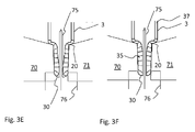
- FIGS. 3A to 3F show on the basis of sectional views a simulation of a forming process according to the invention for forming a syringe cone from a tube 3 for the production of a syringe body.
- the sections of the illustrations run along the center axis of the tube glass 3, around which the tube glass is rotated. Also visible are the rollers 70, 71 and the mandrel 75.
- the drawn in the sectional views of the tube glass initially perpendicular to the center axis of the tube glass lines 20 mark imaginary boundary lines of axial sections of the tube glass 3. Based on these lines, the flow of material during the forming is identified.
- the mandrel 75 protrudes from a foot 76, which serves to form the front cone surface of the syringe.
- the foot 76 is perpendicular to the viewing direction of the Figs. 3A to 3F flat formed component.
- the foot is rotated 90 ° about the longitudinal axis of the forming mandrel 75 so that the foot 76 fits between the rollers 70, 71.
- the overlap of rollers 70, 71 and foot 76 as they descend Fig. 3C can be seen, so does not actually occur.
- a portion of a forming mandrel 75 is shown in plan view.
- A marks a region of the forming mandrel 75 adjoining the tip, in which the lateral surface 81 of the mandrel 75 comes into contact with the glass precursor during the forming process. Therefore, at least this region is preferably that region which is provided or provided with the diffusion layer 81 according to the invention.
- the lateral surface of the mandrel 75 may also include a region 82 which does not have a diffusion layer. This area can be used approximately for receiving the mandrel.
- Fig. 5 is a summary (source: tungsten material properties and applications, Fa. Plansee AG, Reutte, 2000), the modulus of elasticity of tungsten compared to other alloys shown. Clearly visible are the comparatively high modulus of elasticity of tungsten and its high heat resistance.
- Fig. 6 shows a cross-section through a silicated mandrel in a cut-enlargement.
- the mandrel comprises tungsten as the core material.
- the diffusion of the silicon was carried out at a temperature above 650 ° C over a period of more than 8 hours by means of the packing cementation.
- the core material 85 of the mandrel can be seen in transverse section.
- a diffusion zone 86 can be seen, which is located on the surface of the mandrel and protrudes into the interior of the mandrel.
- the thickness of the siliconized diffusion zone 86 is labeled B is about 4 to 6 microns, preferably about 5 microns.
- the siliconized diffusion zone 86 extends approximately 5 ⁇ m measured from the surface of the mandrel into the core material.
- the mandrels are surrounded with a nickel coating. This layer 87 is visible at the forming mandrel 75. This layer 87 finds no use in the use of mandrels in the hot molding of pharmaceutical packaging.
- Fig. 7 shows a cross-section through an alit clergy forming mandrel in a section enlargement.
- the core material 85 of the imaged mandrel 75 is made of tungsten. Further recognizable is an aluminized diffusion zone 88, which is marked C.
- the aluminized diffusion zone extends about 50 to 70 ⁇ m, preferably about 300 ⁇ m, from the surface of the mandrel measured into the core material.
- Fig. 8 shows a further longitudinal section through a silicated mandrel in a cut-out enlargement after use.
- the presence of a diffusion layer 86 is clearly visible.
- a silicon diffusion layer was formed on the mandrel 75 and the mandrel was in use for a longer period of time. So he has a number of about 10,000 cycles, ie forming processes, in the course of the hot molding of syringes through.
- a further longitudinal section through a siliconized mandrel 91 is shown in a cut-out enlargement after use.
- the presence of a diffusion layer 92 is clearly visible.
- the diffusion layer is produced on the basis of silicon and has a diffusion zone D with a thickness of about 10 ⁇ m.
- mandrel 91 has been in use for an extended period of time. So he has a number of about 10,000 cycles, ie forming processes, in the course of the hot molding of syringes through.
- the original outer edge of the mandrel 91 is indicated by the dashed line 93. It can be seen that the outer edge is still in a very good condition. In addition, the external dimensions have hardly changed after use. In particular, there is still a high degree of straightness of the outer edge. The wear of the provided with the siliconized diffusion layer surface of the mandrel 91 is therefore considered to be very low.
- the silicon and tungsten contents were determined.
- the tungsten content is 100% by weight.
- a silicon content of about 22 wt .-% and a tungsten content of about 78 wt .-% could be found.
- a silicon content of about 18 Wt .-% and a tungsten content of about 82 wt .-% determined.
- the silicon content in the diffusion zone decreases inwardly.
- Fig. 10 shows as a comparative example, an untreated tungsten mandrel 101 after use, wherein about 3,000 forming steps were carried out with the imaged mandrel without diffusion layer according to the invention.
- the coloration shows the formation of surface oxides on the mandrel, clearly recognizing the waist 102 in the left portion of the mandrel 101 shown.
- FIG. 11 shows a metallographic longitudinal section through an untreated tungsten mandrel 111 after use, whereby approx. 3,000 shaping steps were carried out with the imaged mandrel without a diffusion layer according to the invention.
- the drawn oval circle 113 the formation of an oxide layer can be seen, whose thickness is about 3 to 5 microns, and which can be removed and replicates.
- a mold according to the invention in particular a forming mandrel, brings a number of advantages. For example, it is possible in this way to continue to use tungsten, which is very suitable for hot-forming hollow-body pre-glass products, without however, this will cause undesirable impurities, especially in the interior of the reshaped glass product.
- the invention is therefore particularly suitable for tungsten-free or tungsten-poor pharmaceutical packaging, in particular syringes.
Landscapes
- Chemical & Material Sciences (AREA)
- Engineering & Computer Science (AREA)
- Materials Engineering (AREA)
- Organic Chemistry (AREA)
- Manufacturing & Machinery (AREA)
- Medical Preparation Storing Or Oral Administration Devices (AREA)
- Infusion, Injection, And Reservoir Apparatuses (AREA)
Abstract
Description
- Die Erfindung betrifft allgemein die Herstellung von Glasprodukten. Insbesondere betrifft die Erfindung ein Formwerkzeug, umfassend einen Formdorn, ein Verfahren und eine Vorrichtung zur Heißformgebung von Glas. Die auf diese Weise erhaltenen Glasprodukte können beispielsweise als Pharmapackmittel verwendet werden.
- Im Zuge der Herstellung von hohlkörperförmigen Glasprodukten ist die Heißformgebung ein wesentlicher Verfahrensschritt. Der Ablauf der Heißformgebung umfasst dabei üblicherweise mehrere aufeinander folgende Aufwärm- und Formprozesse, mit welchen ausgehend von Rohrglas-Körpern die gewünschte Endgeometrie geschaffen wird.
- Hohlkörperförmige Glasprodukte, welche im medizinischen Bereich verwendet werden sollen, unterliegen dabei üblicherweise sehr hohen Anforderungen in Bezug auf mögliche Verunreinigungen, welche aus der Heißformgebung resultieren können. Hieraus folgen sehr hohe Anforderungen an die bei der Heißformgebung verwendeten Formwerkzeuge. Diese hohen Anforderungen beziehen sich insbesondere auf die für die Formwerkzeuge verwendeten Materialien. So wird bei der Herstellung von hohlkörperförmigen Glasprodukten üblicherweise ein Konus geformt, wobei ein Formwerkzeug, umfassend einen Formdorn, zur Anwendung kommt. Dem für den Formdorn verwendeten Material kommt dabei eine zentrale Rolle zu.
- Bei der Herstellung von Pharmapackmitteln oder bei Heißformgebung von medizinischen Aufbewahrungsgefäßen für Medikamente aus Glas, beispielsweise Ampullen, Spritzen, Fläschchen oder Karpulen, wird, neben anderen metallischen Formgebungsmaterialien aus Stahl, auch Wolfram z.B. als Formdornmaterial eingesetzt.
- Reines Wolfram oder Wolfram-Legierungen weisen eine hohe thermomechanische Festigkeit auf, die besonders bei geringen Materialquerschnitten sehr vorteilhaft sind. Dies ist z.B. der Fall bei Formdornen mit einem Durchmesser von weniger als 0,5 mm bis ca. 1 mm. Von daher sind Formdorne umfassend Wolfram oder Wolfram-Legierungen im Kontaktbereich mit dem umzuformenden Glas von Vorteil.
- Während der Herstellung von z.B. Spritzen aus Rohrglas-Körpern, welche üblicherweise auf getakteten Maschinen, beispielsweise auf Rundtaktmaschinen, erfolgt, erwärmt sich der Formdorn bei der Heißformgebung auf Temperaturen von etwa 800°C bis 900°C. Aufgrund der geringen Taktzeiten ist das Material dabei einem häufigen und raschen Temperaturwechsel unterzogen. Der Einfluss von Temperatur, Glasverdampfungsprodukten, Luft, Feuchtigkeit und die tribologische Belastung durch das angepresste, teigige Glas während der Heißformgebung können daher einen Materialabtrag am Formdorn bewirken.
- Dieser Materialabtrag des Formdorns, insbesondere im Kontaktbereich mit dem umzuformenden Glas-Vorprodukt, ist im allgemeinen unerwünscht und führt zu einer Veränderung der Außengeometrie des Formdorns oder einer Reduktion des Durchmessers, wobei die Abnahme des Durchmessers zudem häufig nicht gleichmäßig axial ausgeprägt ist. Dieser Materialabtrag hat verschiedene weitere negative Auswirkungen.
- So führt er u.a. dazu, dass die für die Formgebung vorgegebenen Sollmaße durch die Veränderung der Außengeometrie des Formdorns im Zeitverlauf immer weniger eingehalten und die geforderten Kanaldimensionen damit nur für einen begrenzten Zeitraum eingehalten werden können. Die Standzeit des Formdorns ist damit vergleichsweise gering und/oder zusätzlicher Aufwand für nachträgliche Justagen wird erforderlich. Ferner kann das abgetragene Material in das Innere des gerade geformten Glasproduktes gelangen. So kann der Materialabtrag bei der Konusformung von Spritzen beispielsweise in den sogenannten Konuskanal gelangen.
- Pharmakologische Wirkstoffe, die in den Spritzen gelagert werden, können allerdings mit den wolframhaltigen Verunreinigungen im Innenraum des Glasproduktes in Wechselwirkung treten, wodurch deren Wirksamkeit verändert werden kann. Für bestimmte pharmazeutische Wirkstoffe werden daher zunehmend Glasgefäße gefordert, die einen bestimmten Wolframgehalt unterschreiten.
- Das Dokument
EP 1 809 579 B1 schlägt zur Vermeidung von Wolfram-haltigen Verunreinigungen daher vor, einen Formdorn zu verwenden, der kein Wolfram enthält. - Weiterhin wird in dem Dokument
WO 2012/039705 A2 ein Formdorn vorgeschlagen, welcher eine Schutzschicht als Auflageschicht umfasst. Das Basismaterial kann dabei wolframhaltig sein. Als Schichtmaterial werden ein Neutralglas-eigenes Material bzw. ein Glas vorgeschlagen, welches ein Bestandteil des umzuformenden Glases ist, um auf diese Weise Fremdverunreinigungen auszuschließen. - Eine derartige Beschichtung des Formdorns führt allerdings nicht dazu, dass der nachteilige Effekt des Materialabtrags des Formdorns verhindert werden kann. Dadurch ist die Standzeit eines derartigen Formdorns eher gering.
- Weiterhin kann aufgrund der hohen mechanischen Belastung eine Rissbildung des Schichtmaterials oder auch ein Abplatzen von Schichtbestandteilen auftreten, so dass die Standzeit des Formdorns weiter verringert wird.
- Hieraus ergibt sich die Aufgabe der vorliegenden Erfindung, die darin zu sehen ist, ein Material für ein Formwerkzeug, insbesondere für einen Formdorn, sowie ein Verfahren und eine Vorrichtung zur Formung hohlkörperförmiger Glasprodukte zur Verfügung zu stellen.
- Das Eintragen von unerwünschten Verunreinigungen, insbesondere von Wolfram, in das umzuformende Glasprodukt durch das Formwerkzeug, insbesondere durch den Formdorn, soll dabei sicher ausgeschlossen werden. Insbesondere soll der Innenbereich bzw. der Innenkonus des umgeformten Glasproduktes frei von Verunreinigungen durch das Formwerkzeug, insbesondere durch den Formdorn, bleiben.
- Ferner soll das Formwerkzeug, insbesondere der Formdorn, eine hohe Standzeit aufweisen. Dabei soll der Materialabtrag möglichst verhindert werden, so dass eine besonders hohe Standzeit bei gleichbleibender Qualität ohne zusätzlichen Justageaufwand erreicht werden kann.
- Weiterhin soll auch das Abplatzen von äußeren Bestandteilen des Formwerkzeuges, insbesondere des Formdorns, weitgehend ausgeschlossen werden.
- Schließlich soll auch die Gefahr von Rissbildungen auf der Oberfläche des Formdorns vermieden werden.
- Wünschenswert wäre es ferner, zumindest als Basismaterial das Material Wolfram verwenden zu können, da es über sehr gute thermische und chemische Eigenschaften in Bezug auf die Heißformung von Glasprodukten verfügt.
- Überraschend einfach wird diese Aufgabe durch den Gegenstand der unabhängigen Ansprüche gelöst. Bevorzugte Ausführungsformen und Weiterbildungen der Erfindung sind den jeweiligen Unteransprüchen zu entnehmen.
- Demgemäß betrifft die Erfindung ein Formwerkzeug zum Umformen von hohlkörperförmigen Glas-Vorprodukten, umfassend einen Formdorn zum Umformen wenigstens eines Abschnittes eines erhitzten Bereiches des Glas-Vorproduktes, wobei der Formdorn zumindest ein temperaturstabiles Kernmaterial und eine Diffusionsschicht umfasst und die Diffusionsschicht zumindest denjenigen Bereich der Oberfläche des Formdorns umfasst, welcher während des Umformprozesses im Kontakt mit dem Glas-Vorprodukt steht.
- Des weiteren sieht die Erfindung eine Vorrichtung zum Umformen von Glasprodukten vor, umfassend
- eine Einrichtung zur lokalen Erhitzung eines Bereichs eines Glas-Vorprodukts bis über dessen Erweichungspunkt, und
- zumindest ein Formwerkzeug zum Umformen wenigstens eines Abschnittes eines mit der Einrichtung zur lokalen Erhitzung erhitzten Bereichs des Glas-Vorprodukts, wobei das Formwerkzeug einen erfindungsgemäßen Formdorn umfasst.
- Die Vorrichtung kann einen Brenner zur lokalen Erhitzung umfassen, wobei ferner eine Rotationseinrichtung vorgesehen ist, um das Formwerkzeug und das Glas-Vorprodukt relativ zueinander zu rotieren.
- Das Formwerkzeug kann weiterhin ein Walzenpaar umfassen, welches so angeordnet ist, dass die Walzen des Walzenpaares auf der Oberfläche eines mittels der Rotationseinrichtung in Rotation versetzten Glas-Vorproduktes abrollen, wobei von dem Laserlicht ein zwischen den Walzen liegender Bereich auf dem Umfang des Glas-Vorproduktes beleuchtet wird.
- Die Vorrichtung kann auch in einer weiteren Ausführungsform einen Laser zur lokalen Erhitzung umfassen. Hierbei ist das Formwerkzeug bevorzugt so ausgebildet ist, dass ein Oberflächenbereich des umzuformenden Abschnittes des Glas-Vorproduktes nicht durch das Formwerkzeug abgedeckt wird, wobei der Laser oder eine dem Laser nachgeschaltete Optik so angeordnet ist, dass das Laserlicht bei der Umformung auf den nicht vom Formwerkzeug abgedeckten Bereich eingestrahlt wird, und wobei eine Steuereinrichtung vorgesehen ist, welche den Laser ansteuert so dass zumindest zeitweise das Glas-Vorprodukt während der Umformung durch das Laserlicht erwärmt wird
- Damit eine Erwärmung des Glases eines in der Vorrichtung umzuformenden Glas-Vorprodukts erfolgt, wird ein Laser verwendet, welcher Licht einer Wellenlänge emittiert, für welche das Glas des Glas-Vorprodukts höchstens teiltransparent ist, so dass das Licht zumindest teilweise im Glas absorbiert wird.
- Das mit einer derartigen Vorrichtung durchführbare Verfahren zum Umformen von Glasprodukten basiert entsprechend darauf, dass
- lokal ein hohlkörperförmiges Glas-Vorprodukt bis über dessen Erweichungspunkt erhitzt, und
- mit zumindest einem Formwerkzeug wenigstens ein Abschnitt eines mit einer Einrichtung zur lokalen Erhitzung erhitzten Bereiches des Glas-Vorproduktes umgeformt wird,
- wobei das Formwerkzeug einen erfindungsgemäßen Formdorn wie vorstehend beschrieben umfasst, und
- wobei das Glas-Vorprodukt und das Formwerkzeug relativ zueinander mittels einer Rotationsvorrichtung rotiert werden.
- Das erfindungsgemäße Formwerkzeug ist besonders geeignet für die kontaminationsarme Herstellung von Pharmapackmitteln aus Glas.
- Demgemäß umfasst die Erfindung auch eine Spritze aus Glas, welche hergestellt oder herstellbar ist mit einem Verfahren wie vorstehend beschrieben, welche, insbesondere im Innenbereich, nur sehr geringe oder keine Verunreinigungen, insbesondere nur sehr geringe oder keine Wolfram-Verunreinigungen, aufweist.
- Die Erfinder haben herausgefunden, dass ein Formwerkzeug zum Umformen von hohlkörperförmigen Glas-Vorprodukten, umfassen einen Formdorn mit einer Diffusionsschicht, besonders geeignet ist für die Umformung eines Abschnittes eines mit einer Einrichtung zur lokalen Erhitzung erhitzten Bereiches des Glas-Vorproduktes.
- Als Basis- oder Kernmaterial des Formdorns ist dabei ein Material bevorzugt, welches eine hohe Warmfestigkeit und ein hohes Elastizitätsmodul aufweist, so dass es für die mechanischen Belastungen auch bei Temperaturen im Bereich von 400 °C oder mehr geeignet ist. Ferner sollte es beständig sein gegenüber Säuren und Glasverdampfungsprodukten wie beispielsweise Borate und eine Oxidationsbeständigkeit an Luft bis 400 °C aufweisen, um den Materialabtrag während oder durch die Heißformgebungsprozesse zu vermeiden.
- Ein geeignetes Basismaterial stellen die Edelmetalle oder deren Legierungen dar, beispielsweise Platin. Ein besonders bevorzugtes Basis- oder Kernmaterial für einen erfindungsgemäßen Formdorn sind Wolfram oder Wolframhaltige Legierungen.
- Wolfram zeichnet sich durch eine hohe Beständigkeit gegenüber Säuren wie beispielsweise HF und HCl aus und wird nur gering durch Schwefelsäure angegriffen. Weiterhin weist es eine gute Oxidationsbeständigkeit an Luft bis 400°C auf. Zudem sind eine hohe Warmfestigkeit und ein hohes Elastizitätsmodul günstig für eine Verwendung als Kernmaterial für einen Formdorn. Unter Kernmaterial ist dabei ein Material des Formdorns zu verstehen, welches wesentlich für die Heißformgebung ist.
- Überraschend kann der Materialabtrag von Kernmaterial des Formdorns, insbesondere von Wolfram-haltigen Kernmaterial, dadurch unterbunden oder zumindest sehr stark reduziert werden, dass die äußere Randzone des Kernmaterials mit einer Diffusionsschicht versehen wird. Die Diffusionsschicht zeichnet sich durch ein zusätzliches, von dem Kernmaterial abweichendes Material aus.
- Diffusionsschichten zeichnen sich weiterhin dadurch aus, dass sich die Schichtzusammensetzung in Richtung der Oberflächennormalen verändert. Sie können durch verschiedene Verfahren auf den Werkstoff aufgebracht werden. Diffusionsschichten können auch durch Implantationstechniken erzeugt werden.
- In der Regel erfolgt die thermische Eindiffusion des abgeschiedenen Materials in den Grundwerkstoff bei Temperaturen zwischen 500 °C und 1200 °C, wobei die genauen Temperaturen von dem jeweiligen Kernmaterial und dem eingebrachten Material abhängen. Diffusionsschichten können beispielsweise durch Hochtemperatur-CVD-Verfahren, wie zum Beispiel Packzementation, erzeugt werden.
- Ein derartiges Verfahren ist etwa in dem Dokument
DE 691 10 286 T2 oder in dem DokumentWO 2012/089200 A1 beschrieben. - Die Packzementation setzt die Diffusion eines Materials oder mehrerer Materialien zur Bildung einer Oberflächenbeschichtung ein. Dabei wird ein Substratmaterial mit einem Material einer Metallquelle in Kontakt gebracht, so dass ein Metall aus dem Material der Metallquelle in das Substratmaterial diffundieren kann.
- Bei der Packzementation wird ein Substratmaterial in einer Pulvermischung eingebracht, die sowohl ein Metall, welches mit dem Substratmaterial reagieren soll, als auch ein inertes Material aufweist. Zusätzlich kann ein Aktivator aus der Gruppe der Halogenide verwendet werden, der als Feststoff oder flüssiger Stoff bei Raumtemperatur, zum Beispiel FeCl3, AlCl3, NH4Cl im Pack vorliegt oder über das Gas beispielsweise als HCl oder direkt als SiCl4 zugeführt wird und das Material der Metallquelle in einen gasförmigen Zustand versetzt.
- Das Metall kann auch im gasförmigen Zustand als Reinstoff oder als Verbindung zugeführt werden. Auch kann das Metall im Prozess aufschmelzen und in diesem Zustand mit dem Substrat reagieren. Das gasförmige Material der Metallquelle gelangt zum Substratmaterial und scheidet sich als Metall auf der Oberfläche ab (Zersetzungsreaktion). Bedingt durch die hohe Temperatur diffundiert das abgeschiedene Metall in das Substratmaterial ein und bildet eine Diffusionsschicht im oberflächennahen Bereich des Substartmaterials. Abhängig von der gewählten Temperatur, der Prozessdauer und der Art des Metalls können unterschiedlich dicke Diffusionszonen im Substratmetarial gebildet werden. Ebenfalls abhängig von der Materialkombination und den Prozessparametern kann es innerhald der Diffusionszone zu einer Phasenbildung kommen. Je nach Materialkombination wird zusätzlich eine reduzierende Gasatmosphäre bei dem Beschichtungsprozess erzeugt, in dem ein entsprechendes Gasgemisch die Beschichtungskammer durchströmt. Dieser Prozess kann auch im Unterdruck (Vakuum) erfolgen.
- Das Vorhandensein anderer Elemente in der Diffusionszone und/oder eine Phasenbildung kann dazu führen, dass die Eigenschaften in der Randzone, u.a. das Korrosionsverhalten des Substratmaterials, verändert werden.
- Dabei kann als Kernmaterial des Formdorns Wolfram oder eine Wolfram-haltige Legierung verwendet werden. Die erzeugte Diffusionsschicht ist von einer hohen Dichte und von gleichmäßiger Dicke gekennzeichnet.
- Der Formdorn mit Diffusionsschicht zeichnet sich ferner dadurch aus, dass die Verunreinigungen, die durch die Umformung in das umzuformende Glasprodukt durch das Formwerkzeug eingetragen werden, auf ein Minimum reduziert werden können. Dabei bleibt insbesondere ein Innenbereich bzw. ein Innenkonus des umgeformten Glasproduktes frei von Verunreinigungen, insbesondere von Verunreinigungen mit Wolfram.
- Mit dem erfindungsgemäßen Formdorn mit Diffusionsschicht können daher Spritzen als Pharmapackmittel erzeugt werden, welche insbesondere innerhalb des Hohlraums und/oder innerhalb des inneren Konusbereiches der Spritze eine sehr geringe Kontamination aufweisen.
- Die Kontamination des Elementes Wolfram kann dabei in einem Bereich von weniger als 500 ng, bevorzugt weniger als 300 ng und besonders bevorzugt weniger als 100 ng jeweils pro Spritze liegen. Dabei kann eine sehr geringe Verunreinigung mit Wolfram vorliegen, wobei ein Gehalt an Wolfram, insbesondere im Innenbereich der Spritze, insbesondere in einem Bereich von mehr als 0,1 ng, mehr als 1 ng, mehr als 10 ng vorhanden kann. Eine derartige Menge an Wolfram ist im Allgemeinen unschädlich.
- Der Nachweis der Wolfram-Kontamination erfolgt mittels einer wässrigen Extraktions-Methode, wobei das innere Volumen der Spritze ausgewaschen wird. Dabei wird bei erhöhter Temperatur gearbeitet (typisch sind 50°C bis über 100°C). Der chemische Nachweis vom Wolfram erfolgt im Eluat mittels ICP-MS.
- Ein weiterer Vorteil der Erfindung ist darin zu sehen, dass abhängig vom Konzentrationsgradienten ein Unterschied im Ausdehnungsverhalten zwischen dem Kernmaterial und der Diffusionsschicht besser kompensiert werden kann im Vergleich zu Auflageschichten, welche mit dem Basismaterial häufig nur gering verzahnt sind und einen geringeren Verbund haben. Hierdurch kann die Gefahr eines Abplatzens von äußeren Bestandteilen des Formdorns weitgehend verringert werden. Gleichzeitig ist auch die Gefahr von Rissbildungen minimiert.
- Entsprechend der Wirkungsweise kann das eindiffunduierte Material als ein Reservoir für die Neubildung einer äusseren Passivschicht wirken, wenn es zu äusseren Beschädigungen kommt. Hierdurch kann eine sehr hohe Standzeit des Formdorns erreicht werden. Zudem ist es so möglich, eine besonders gleichbleibende hohe Qualität des umgeformten Glasproduktes zu erreichen, ohne dass häufige, zusätzliche Justagetätigkeiten an der Vorrichtung notwendig werden.
- Wie vorstehend ausgeführt können durch das eindiffundierte Material intermetallische Phasen im oberflächennahen Bereich des Basismaterials, also des Kernmaterials des Formdorns, gebildet werden. Diese bilden die sogenannte Diffusionszone aus. In der äußersten Zone kann eine stabile Oxidschicht ausgebildet werden, die die Oxidation des darunter liegenden Materials verhindert und eine Passivschicht darstellt. Hierdurch können Oxidationsschutzschichten erzeugt werden, die thermodynamisch stabile Oxide, ganz allgemein z.B. Siliziumoxid (SiO2), Aluminiumoxid (Al2O3), Titanoxid (TiO2) oder Chromoxid (Cr2O3), ausbilden. Diese Passivschicht verhindert weiterführende Oxidation.
- Diese Metalle, beispielsweise Aluminium, Silizium, Chrom, besitzen eine höhere Affinität gegenüber Sauerstoff als Wolfram und bilden thermodynamisch sehr stabile Oxide.
- Ein erfindungsgemäßer Formdorn mit Diffusionsschicht ist dadurch gekennzeichnet, dass der Mindestgehalt des Diffusionsmaterials, gemessen an der Oberfläche des Formdorns, wenigstens 40 Atom % beträgt. Dies gilt beispielsweise für Silizium als Diffusionsmaterial.
- In einer besonders bevorzugten Ausführungsform wird als Kernmaterial Wolfram ausgewählt und als Diffusionsmaterial Silizium. Mittels der Packzementation kann eine oberflächennahe Eindiffusion von elementarem Silizium in die äußeren Randzonen des Formdorns erreicht werden. Hierdurch können im oberflächennahen Bereich die intermetallischen Verbindungen, beispielsweise Wolframsilizide in Form von WSi2, ausgebildet werden.
- Das gebildete Wolframsilizid ist äusserst oxidationsbeständig, vergleichbar mit Molybdänsilizid. Diese sogenannte Silizierung der Wolfram- oder Wolframhaltigen Oberfläche des Formdorns führt bei Temperaturen oberhalb von 500 °C an sauerstoffhaltiger Atmosphäre unter anderem zur Bildung einer stabilen SiO2-Schicht an der Formdornoberfläche, so dass der umgebende Sauerstoff nicht mit dem Wolfram reagiert, sondern vom Silizium als Siliziumoxid gebunden wird. Das Oxidationsverhalten wird somit deutlich verbessert, welches einen sehr positiven Einfluß auf den Korrosionsverschleiß des Formdorns im Einsatz hat. Eine Wärmebehandlung vor dem Einsatz eines sogenannten silizierten Formdornes an sauerstoffhaltiger Atmosphäre führt zur Ausbildung einer Passivschicht. Die Wärmebehandlung kann zwischen 500 °C und 800 °C an Luft für eine Dauer von ca. 1 h durchgeführt werden.
- Die Schichtdicke der Diffusionsschicht des silizierten Formdornes liegt dabei in einem Bereich von 1 bis 200 µm, bevorzugt von 1 bis 100 µm und besonders bevorzugt in einem Bereich von 1 bis 20 µm.
- In einer weiteren bevorzugten Ausführungsform kann eine Diffusionsschicht basierend auf Aluminium in dem Formdorn erzeugt werden. Auch hier kann das Kernmaterial Wolfram umfassen oder Wolfram-haltig sein. Auch diese Diffusuionsschicht bewirkt bei hohen Temperaturen an Luft die Ausbildung eine stabilen Aluminiumoxidschicht, die die weitere Oxidation des Grundmaterials verhindert. Dadurch wird der Korrosionsverschleiß des Formdorns im Heissformgebungsprozess mit Glas deutlich reduziert.
- Eine Wärmebehandlung vor dem Einsatz dieses sogenannten alitierten Formdorns an sauerstoffhaltiger Atmosphäre führt zur Ausbildung einer Passivschicht. Die Wärmebehandlung kann zwischen 500 °C und 800 °C an Luft für eine Dauer von ca. 1 h durchgeführt werden. Eine Vorabpassivierung bewirkt im Einsatz eine weitere Reduktion der Abgabe von Wolframverbindungen in das Glasprodukt.
- Die Schichtdicke der Diffusionsschicht des alitierten Formdorns liegt dabei in einem Bereich von 1 bis 300 µm, bevorzugt 5 bis 90 µm.
- Ein mit einer auf Silizium oder Aluminium basierender Diffusionsschicht ausgebildeter Formdorn mit einem Kernmaterial, umfassend Wolfram oder Wolframhaltige Legierungen, bietet vielfältige Vorteile.
- Hierzu gehören eine deutlich erhöhte Standzeit, da der Massenverlust durch Materialabtrag oder durch Bildung flüchtiger Oxide durch den silizierten oder alitierten oberflächennahen Bereich deutlich reduziert ist.
- Ein weiterer großer Vorteil liegt darin, dass durch den geringeren Korrosionsverschleiß deutlich weniger Partikel im Kontaktbereich mit dem umzuformenden Glas-Vorprodukt, beispielsweise im Kontaktbereich mit dem Konuskanal einer Spritze, abgelagert werden. Gleichzeitig werden deutlich weniger flüchtige Wolframkomponenten in das Innere des hohlkörperförmigen Glasproduktes eingebracht, etwa in den Innenraum der Spritze. Der chemisch analytisch nachweisbare Wolfram-Gehalt wird somit erheblich reduziert. Hierdurch ist das erfindungsgemäße Formwerkzeug, insbesondere der erfindungsgemäße Formdorn, besonders geeignet zur Verwendung in der Heißformgebung von Glasprodukten, welche als Pharmapackmittel eingesetzt werden.
- Zusätzlich ist eine besonders hohe Qualität der Maßeinhaltung gegeben, da der Materialabtrag des Fordorns reduziert ist. Dadurch kann ein enges Toleranzfeld bezüglich der Geometrie des Glasproduktes eingehalten werden.
- Das Formwerkzeug, insbesondere der Formdorn, kann Wolfram oder Wolframlegierungen umfassen. In einer besonders bevorzugten Ausführungsform umfasst das Formwerkzeug daher einen Formdorn mit einem Kernmaterial, welches einen Wolframanteil von wenigstens 70 Gew.-%, bevorzugt wenigstens 90 Gew.-%, besonders bevorzugt wenigstens 95 Gew.-% und ganz besonders bevorzugt wenigstens 99,9 Gew.-% aufweist.
- Der Formdorn kann auch modifizierte Wolfram-Basislegierungen als Kernmaterial umfassen. Als besonders geeignet haben sich folgende ODS-Wolfram-Basislegierungen herausgestellt: Wolfram-Zirkonoxid (W-ZrO2), Wolfram-Yttriumoxid (W-CeO2) sowie Wolfram-Lanthanoxid (W-La2O3). Der Begriff ODS bzw. ODS-Legierung steht dabei für die Bezeichnung "Oxid dispersed strengthed" (Oxid-Dispersions verfestigt) bzw. Oxid-Dispersionsverfestigte Legierung.
- Im Fall von Wolfram-Zirkonoxid (W-ZrO2) liegt der Anteil von dispersoid zugesetztem ZrO2 bei 0,01 Gew.-% bis zu 2,5 Gew.-%, bevorzugt bei 0,1 bis zu 2,2 Gew.-%, besonders bevorzugt bei 0,7 bis 0,9 Gew.-%.
- Im Fall von Wolfram-Yttriumoxid (W-CeO2) liegt der Anteil von dispersoid zugesetztem CeO2 bei 0,01 Gew.-% bis zu 2,5 Gew.-%, bevorzugt bei 0,1 Gew.-% bis zu 2,5 Gew.-%, und besonders bevorzugt bei 1,8 Gew.-% bis zu 2,2 Gew.-%.
- Im Fall von Wolfram-Lanthanoxid (W-La2O3) liegt der Anteil von dispersoid zugesetztem La2O3 bei 0,01 Gew.-% bis zu 2,5 Gew.-%, bevorzugt bei 0,1 Gew.-% bis zu 2,5 Gew.-% und besonders bevorzugt bei 1,8 Gew.-% bis zu 2,2 Gew.-%.
- Ergänzend dazu erweisen sich mit Kalium dotierte Legierungen als besonders geeignet. Kalium dotierte Wolfram-Legierungen weisen eine erhöhte Rekristallisations- und Erholungstemperatur auf.
- Besonders geeignet sind Wolfram-Basislegierungen mit einem Kaliumanteil zwischen 5 und 100 ppm, bevorzugt zwischen 30 und 80 ppm und besonders bevorzugt zwischen 50 und 70 ppm.
- Neben warmfesten reinem Wolfram oder Wolframlegierungen kann das Kernmaterial des Formdorns auch Edelmetall oder deren Legierung umfassen. Hierzu gehören etwa Platin oder Rhodium oder deren Legierungen.
- Der Formdorn kann weitere Materialien umfassen. So kann der Formdorn beispielsweise, etwa aus Stabilitätsgründen, ein keramisches Basismaterial umfassen, auf dem das Kernmaterial des Formdorns aufgebracht ist.
- Vorzugsweise umfasst die Diffusionsschicht zumindest denjenigen Bereich der Oberfläche des Formdorns, welcher während des Umformprozesses im Kontakt mit dem Glas-Vorprodukt steht. Dieses ist im Allgemeinen zumindest die vordere, der Spitze des Formdorns zugewandte äußere Mantelfläche.
- Die Erfindung wird nachfolgend anhand bevorzugter Ausführungsformen und unter Bezugnahme auf die beigefügten Figuren detaillierter beschrieben. Weitere Einzelheiten der Erfindung ergeben sich aus der Beschreibung der dargestellten Ausführungsbeispiele und den angefügten Ansprüchen.
-
- Fig. 1
- Teile einer Vorrichtung zur Umformung von Rohrglas,
- Fig. 2
- ein Transmissionsspektrum eines Glases eines Glas-Vorprodukts,
- Fig. 3A-3F
- Schnittansichten durch ein Rohrglas im Verlauf des Umformprozesses,
- Fig. 4
- einen Abschnitt eines Formdorns mit einer Diffusionsschicht in einer Draufsicht,
- Fig. 5
- eine Übersicht über Materialeigenschaften von Wolfram,
- Fig. 6
- einen Querschliff durch einen silizierten Formdorn in einer Ausschnittvergrößerung,
- Fig. 7
- einen Querschliff durch einen alitierten Formdorn in einer Ausschnittvergrößerung,
- Fig. 8
- einen Längsschliff durch einen silizierten Formdorn in einer Ausschnittvergrößerung nach dem Einsatz,
- Fig. 9
- einen weiteren Längsschliff durch einen silizierten Formdorn in einer Ausschnittvergrößerung nach dem Einsatz,
- Fig. 10
- einen nicht behandelten Wolfram-Dorn nach dem Einsatz, und
- Fig. 11
- einen metallographischen Längsschliff durch einen nicht behandelten Wolfram-Dorn nach dem Einsatz.
- Bei der nachfolgenden detaillierten Beschreibung bevorzugter Ausführungsformen bezeichnen um der Klarheit willen gleiche Bezugszeichen im Wesentlichen gleiche Teile in oder an diesen Ausführungsformen. Zur besseren Verdeutlichung der Erfindung sind die in den Figuren dargestellten bevorzugten Ausführungsformen jedoch nicht immer maßstabsgerecht gezeichnet.
- In
Fig. 1 ist ein Ausführungsbeispiel einer Vorrichtung 1 zur Durchführung des erfindungsgemäßen Verfahrens dargestellt. - Die als Ganzes mit dem Bezugszeichen 1 bezeichnete Vorrichtung des in
Fig. 1 gezeigten Ausführungsbeispiels ist zur Umformung von Glas-Vorprodukten in Gestalt von Rohrgläsern 3 ausgebildet. Im Speziellen wird die Vorrichtung zur Herstellung von Glas-Spritzenkörpern verwendet, wobei mit den inFig. 1 gezeigten Elementen der Vorrichtung 1 aus dem Rohrglas der Konus des Spritzenkörpers geformt wird. - Das Herstellen des Konus aus dem Rohrglas mittels der Vorrichtung 1 basiert darauf, dass lokal ein Bereich eines Rohrglases 3, hier dessen Ende 30, bis über dessen Erweichungspunkt erhitzt und mit zumindest einem Formwerkzeug wenigstens ein Abschnitt des erhitzten Endes umgeformt wird. Im abgebildeten Beispiel umfasst die Einrichtung zur lokalen Erhitzung einen Laser 5, welcher Licht einer Wellenlänge emittiert, für welche das Glas des Rohrglases 3 höchstens teiltransparent ist, so dass das Licht zumindest teilweise im Glas absorbiert wird.
- Anstelle des in
Fig. 1 gezeigten Lasers 5 zur lokalen Erhitzung eines hohlkörperförmigen Glas-Vorproduktes ist es selbstverständlich auch möglich, andere Einrichtungen zur lokalen Erhitzung zu verwenden, welche im Rahmen der Heißformgebung von Glas typischerweise eingesetzt werden. Dies können beispielsweise auch Brenner, etwa Gasbrenner, sein. Da die Verwendung derartiger Einrichtungen weitgehend bekannt ist, wird auf eine detaillierte Beschreibung an dieser Stelle verzichtet. - Der Laserstrahl 50 nach
Fig. 1 wird mittels einer Optik 6 auf das Rohrglas 3 gerichtet. Während des Umform-Prozesses werden das Formwerkzeug 7 und das Glas-Vorprodukt 3 relativ zueinander mittels einer Rotationseinrichtung 9 rotiert. Im Allgemeinen ist es dabei zweckmäßig, wie auch im gezeigten Beispiel das Rohrglas 3 mit Drehachse entlang der axialen Richtung des Rohrglases 3 zu rotieren. Dazu umfasst die Rotationseinrichtung 9 einen Antrieb 90 mit Futter 91, mit welchem das Rohrglas 3 gehaltert wird. Denkbar wäre auch eine umgekehrte Konfiguration, bei welchem das Rohrglas festgehalten wird und das Formwerkzeug 7 um das Rohrglas rotiert. - Das Formwerkzeug 7 umfasst bei dem in
Fig. 1 gezeigten Ausführungsbeispiel zwei Walzen 70, 71, welche bei Rotation des Rohrglases 3 auf dessen Oberfläche abrollen. Dabei wird das Ende 30 des Rohrglases 30 komprimiert, indem die Walzen in radialer Richtung des Rohrglases 3 aufeinander zu geführt werden. Die radiale Bewegung ist inFig. 1 anhand von Pfeilen an den Drehachsen der Walzen 70, 71 verdeutlicht. Weiterhin ist ein Formdorn 75 als Bestandteil des Formwerkzeugs 7 vorgesehen. Dieser Formdorn 75 wird in die Öffnung des Rohrglases 3 an dessen umzuformenden Ende 30 eingeführt. Mittels des Formdorns 75 wird der Konuskanal des Spritzenkörpers geformt. Der Formdorns 75 kann drehbar gelagert sein, um zusammen mit dem Rohrglas 3 zu rotieren. Ebenso möglich ist es, das rotierende Glas über den festgehaltenen Formdorn gleiten zu lassen. - Um ein Anhaften zu vermeiden, kann hierzu, wie generell bei über die Glasoberfläche gleitenden Formwerkzeugen, ein Trenn- oder Schmiermittel verwendet werden, welches die Reibung bei der Gleitbewegung herabsetzt. Weiterhin ist es möglich, ein Schmiermittel zu verwenden, welches bei den bei der Umformung eingesetzten Temperaturen verdampft. Bei der Verwendung eines solchen Schmiermittels können so vorteilhaft Schmier-, beziehungsweise Trennmittelrückstände auf dem fertig gestellten Glasprodukt vermieden werden.
- Zwischen den Walzen 70, 71 ist es möglich, den Laserstrahl 50 auf das Rohrglas zu richten, ohne dass der Laserstrahl 50 durch das Formwerkzeug unterbrochen wird. Demgemäß ist das Formwerkzeug so ausgebildet, dass ein Oberflächenbereich des umzuformenden Abschnittes des Rohrglases nicht durch das Formwerkzeug abgedeckt wird, so dass mittels der dem Laser nachgeschalteten Optik 6 das Laserlicht bei der Umformung auf den nicht vom Formwerkzeug abgedeckten Bereich eingestrahlt wird. Im Speziellen wird vom Laserlicht ein zwischen den Walzen 70, 71 liegender Bereich 33 auf dem Umfang des Rohrglases 3 beleuchtet.
- Eine Steuereinrichtung 13 steuert den Umformvorgang. Insbesondere wird mittels der Steuereinrichtung 13 der Laser 5 so angesteuert wird, dass zumindest zeitweise das Rohrglas 3 während der Umformung durch das Laserlicht erwärmt wird.
- Die Optik 6 der in
Fig. 1 gezeigten Vorrichtung 1 umfasst einen Umlenkspiegel 61, sowie eine Zylinderlinse 63. - Mittels der Zylinderlinse 63 wird der Laserstrahl 50 entlang der axialen Richtung des Rohrglases 3 zu einem Fächerstrahl 51 aufgeweitet, so dass der vom Laserlicht ausgeleuchtete Bereich 33 in axialer Richtung des Rohrglases 3 entsprechend gedehnt wird. Da das Rohrglas 3 rotiert, während das Laserlicht eingestrahlt wird, verteilt sich die eingestrahlte Leistung in Umfangsrichtung auf dem Rohrglas, so dass ein zylinderförmiger Abschnitt, beziehungsweise unabhängig von der Form des Glas-Vorprodukts allgemein ein Abschnitt in axialer Richtung entlang der Drehachse erwärmt wird. Dieser Abschnitt hat eine Länge, die vorzugsweise mindestens so groß ist, wie der umzuformende Abschnitt. Letzterer hat eine Länge, die im Wesentlichen durch die Breite der Walzen bestimmt wird. Um spezielle Verteilungen der Laserleistung in axialer Richtung des Rohrglases zu erzielen, kann alternativ oder zusätzlich zur Zylinderlinse 63 auch vorteilhaft ein diffraktives optisches Element verwendet werden.
- Der Formungsprozess wird mittels der Steuereinrichtung 13 gesteuert. Unter anderem steuert die Steuereinrichtung 13 die Laserleistung. Weiterhin wird auch die Bewegung der Formwerkzeuge 70, 71, 75 kontrolliert. Ebenfalls gesteuert werden kann auch die Rotationseinrichtung 9, dabei insbesondere die Drehzahl des Antriebs 90, gegebenenfalls auch das Öffnen und Schließen des Futters 91.
- Bei der Formung von Spritzenkörpern aus Glas sind für den Laser 5 im allgemeinen Strahlungsleistungen von weniger als 1 Kilowatt ausreichend, um eine schnelle Erwärmung auf die Erweichungstemperatur zu gewährleisten. Nach Erreichen der für die Heißumformung vorgesehenen Temperatur kann dann von der Steuereinrichtung 1 die Laserleistung reduziert werden, so dass die eingestrahlte Laserleistung nur noch die Abkühlung kompensiert. Bei der Herstellung von Spritzenkörpern reichen dazu im Allgemeinen Leistungen zwischen 30 und 100 Watt.
- Die Regelung der Laserleistung kann insbesondere auch anhand der Temperatur des Rohrglases 3 vorgenommen werden. Dazu kann in der Steuereinrichtung 13 ein Regelprozess implementiert sein, welcher die Laserleistung anhand der mittels einer Temperatur-Messeinrichtung gemessenen Temperatur regelt, um eine vorgegebene Temperatur oder ein vorgegebenes Temperatur/Zeit-Profil am Glas-Vorprodukt einzustellen. Als Temperatur-Messeinrichtung ist bei dem in
Fig. 1 gezeigten Beispiel ein Pyrometer 11 vorgesehen, welches die Wärmestrahlung des Glasrohres an dessen durch den Laser 5 erwärmten Ende 31 misst. Die Messwerte werden der Steuereinrichtung 13 zugeführt und im Regelprozess zur Einstellung der gewünschten Temperatur verwendet. - Besonders vorteilhaft bei einer Anordnung, wie sie beispielhaft
Fig. 1 zeigt, ist, dass das Laserlicht die Formwerkzeuge nicht direkt erwärmt. Dies führt dazu, dass die Formwerkzeuge trotz einer Erwärmung des Glas-Vorprodukts während der Umformung im Allgemeinen nicht stärker erwärmt werden als bei einem Prozess mit vorangehender Erwärmung durch Brenner. Insgesamt wird auf diese Weise weniger Wärmeenergie erzeugt und diese Wärmeenergie auch noch gezielter in das Glas-Vorprodukt eingebracht. Damit wird insgesamt die Aufheizung der gesamten Vorrichtung und damit unter anderem durch Wärmedehnungen entstehende Einlaufphänomene reduziert. - Ein bevorzugtes Glas für die Fertigung von Spritzenkörpern ist Borosilikatglas. Besonders bevorzugt wird dabei alkaliarmes Borosilikatglas, insbesondere mit einem Alkaligehalt von weniger als 10 Gewichtsprozent. Borosilikatglas eignet sich generell gut aufgrund der typischerweise hohen Temperaturwechselbeständigkeit. Diese ist günstig, um bei den schnellen Prozesszeiten, wie sie mit der Erfindung erzielbar sind, schnelle Aufheizrampen realisieren zu können.
- Ein geeignetes alkaliarmes Borosilikatglas weist folgende Bestandteile in Gewichtsprozent auf:
SiO2 75 Gew% B2O3 10,5 Gew % Al2O3 5 Gew % Na2O 7 Gew % CaO 1,5 Gew % - Ein Transmissionsspektrum des Glases zeigt
Fig. 2 . Die angegebenen Transmissionswerte beziehen sich auf eine Glasdicke von einem Millimeter. Anhand vonFig. 2 ist ersichtlich, dass die Transmission des Glases bei Wellenlängen oberhalb von 2,5 Mikrometern absinkt. Oberhalb von 5 Mikrometern ist das Glas auch bei sehr dünnen Glasdicken praktisch opak. - Die in
Fig. 2 gezeigte Abnahme der Transmission im Wellenlängenbereich oberhalb von 2,5 Mikrometern ist nicht wesentlich von der genauen Zusammensetzung des Glases abhängig. So können bei ähnlichen Transmissionseigenschaften die oben angegebenen Gehalte der Bestandteile bevorzugter Borosilikatgläser können auch um jeweils 25 % vom angegebenen Wert variieren. Weiterhin können außer Borosilikatglas selbstverständlich auch andere Gläser eingesetzt werden. Sofern diese bei der Wellenlänge des Lasers höchstens teiltransparent sind, kann zur Erhitzung eine Laserquelle verwendet werden. - Die
Figuren 3A bis 3F zeigen anhand von Schnittansichten eine Simulation eines erfindungsgemäßen Umformprozesses zur Ausformung eines Spritzenkonus aus einem Rohrglas 3 für die Herstellung eines Spritzenkörpers. Die Schnitte der Darstellungen verlaufen entlang der Mittenachse des Rohrglases 3, um welche das Rohrglas rotiert wird. Ebenfalls zu erkennen sind die Walzen 70, 71 und der Dorn 75. - Die in den Schnittansichten des Rohrglases eingezeichneten, anfänglich senkrecht zur Mittenachse des Rohrglases verlaufenden Linien 20 kennzeichnen gedachte Grenzlinien von axialen Abschnitten des Rohrglases 3. Anhand dieser Linien wird der Materialfluss bei der Umformung kenntlich gemacht.
- Der Formdorn 75 ragt aus einem Fuß 76 heraus, der zur Formung der vorderen Konusfläche der Spritze dient. Der Fuß 76 ist ein senkrecht zur Betrachtungsrichtung der
Fig. 3A bis 3F flach ausgebildetes Bauteil. Anders als dargestellt ist in der tatsächlichen Vorrichtung der Fuß dabei um 90° um die Längsachse des Formdorns 75 gedreht, so dass der Fuß 76 zwischen die Walzen 70, 71 passt. Die Überlappung von Walzen 70, 71 und Fuß 76, wie sie abFig. 3C zu erkennen ist, tritt also tatsächlich nicht auf. - Eine Berührung der Walzen 70, 71 und die beginnende Verformung erfolgt ab der in
Fig. 3C gezeigten Position. Es erfolgt nun eine Kompression des Rohrglases 3 durch die radial einwärts zur Mittenachse des Rohrglases bewegten Walzen 70, 71. Bei dem inFig. 3E gezeigten Stadium berührt der Formdorn 75 innenseitig das Rohrglas und formt den Kanal des Spritzenkonus. Bei dem inFig. 3F gezeigten Stadium schließlich ist die Ausformung des Spritzenkonus bereits beendet. Anschließend werden die Formwerkzeuge vom ausgeformten Spritzenkonus 35 weggefahren. Alle Formungsschritte zur Ausformung des Spritzenkonus 35 wurden mithin mit den gleichen Formwerkzeugen 70, 71, 75 und dem Fuß 76 durchgeführt. Eine derartige Umformungsstation führt daher alle Heiß-Umformungsschritte an einem Abschnitt des Glas-Vorprodukts aus. Es kann sich nun eine Ausformung des Spritzenflansches, beziehungsweise der Fingerauflage am anderen Ende des Rohrglases erfolgen. - Ab dem Verformungsstadium, wie es in
Fig. 3E dargestellt ist, ist gut zu erkennen, dass die radiale Kompression am Spritzenkonus 35 zu einer Verdickung der Wandstärke führt. Hier besteht nun die Möglichkeit, durch die Einstellung einer entsprechenden Temperaturverteilung wie oben beschrieben, einen gewissen Materialfluss vom Ende 30 weg zu erzeugen. Ebenso kann es an den umlaufenden Kanten des ausgeformten Rohrglases im Übergangsbereich zwischen Spritzenzylinder 37 und Spritzenkonus 35 zu einer verminderten Wandstärke kommen. Auch diesem Effekt kann durch Einstellung eines axial inhomogenen Leistungseintrags über die Regelung der axialen Verteilung der Laserleistung begegnet werden. - In
Fig. 4 ist ein Abschnitt eines Formdorns 75 in einer Draufsicht dargestellt. Ausgehend von der Spitze 80 des Formdorns 75 ist mit A ein an die Spitze angrenzender Bereich des Formdorns 75 markiert, in dem die Mantelfläche 81 des Formdorns 75 während des Umformprozesses in Kontakt mit dem Glas-Vorprodukt kommt oder kommen kann. Zumindest dieser Bereich ist daher vorzugsweise derjenige Bereich, der mit der erfindungsgemäßen Diffusionsschicht 81 versehen ist oder versehen wird. Die Mantelfläche des Formdorns 75 kann auch einen Bereich 82 umfassen, welcher keine Diffusionsschicht aufweist. Dieser Bereich kann etwa für die Aufnahme des Formdorns verwendet werden. - In
Fig. 5 ist in einer Übersicht (Quelle: Wolfram-Werkstoffeigenschaften und Anwendungen, Fa. Plansee AG, Reutte, 2000) das Elastizitätsmodul von Wolfram im Vergleich zu anderen Legierungen dargestellt. Deutlich zu erkennen sind das vergleichsweise hohe E-Modul von Wolfram sowie dessen hohe Warmfestigkeit. -
Fig. 6 zeigt einen Querschliff durch einen silizierten Formdorn in einer Ausschnittvergrößerung. Der Formdorn umfasst als Kernmaterial Wolfram. Das Eindiffundieren des Siliziums erfolgte bei einer Temperatur oberhalb 650 °C über einen Zeitraum von mehr als 8 Stunden mittels der Packzementation. - Das Kernmaterial 85 des Formdorns ist im Querschliff zu erkennen. Ebenso ist eine Diffusionszone 86 erkennbar, welche sich an der Oberfläche des Formdorns befindet und in das Innere des Formdorns hineinragt. Die Dicke der silizierten Diffusionszone 86 ist mit B gekennzeichnet liegt bei etwa 4 bis 6 µm, bevorzugt bei etwa 5 µm. Somit reicht die silizierte Diffusionszone 86 etwa 5 µm von der Oberfläche des Formdorns aus gemessen in das Kernmaterial hinein.
- Um während der metallographischen Präparation, insbesondere dem Schleifen und dem Polieren der Dorne, den oberflächennahen Bereich zu schützen, werden die Dorne mit einer Nickelbeschichtung umgeben. Diese Schicht 87 ist bei dem Formdorn 75 sichtbar. Diese Schicht 87 findet bei der Verwendung der Dorne keinen Einsatz bei der Heissformgebung von Pharmapackmitteln.
-
Fig. 7 zeigt einen Querschliff durch einen alitierten Formdorn in einer Ausschnittvergrößerung. Das Kernmaterial 85 des abgebildeten Formdorns 75 ist aus Wolfram hergestellt. Weiterhin erkennbar ist eine alitierte Diffusionszone 88, welche mit C gekennzeichnet ist. Die alitierte Diffusionszone reicht ca. 50 bis 70 µm, bevorzugt etwa 300 µm von der Oberfläche des Formdorns aus gemessen in das Kernmaterial hinein. -
Fig. 8 zeigt einen weiteren Längsschliff durch einen silizierten Formdorn in einer Ausschnittvergrößerung nach dem Einsatz. Das Vorhandensein einer Diffusionsschicht 86 ist deutlich erkennbar. Bei diesem Beispiel wurde eine Silizium-Diffusionsschicht auf dem Formdorn 75 erzeugt und der Formdorn war über eine längerer Zeitraum im Einsatz. So hat er eine Anzahl von ca. 10.000 Zyklen, also Umformprozessen, im Zuge der Heißformgebung von Spritzen durchlaufen. - In
Fig. 9 ist ein weiterer Längsschliff durch einen silizierten Formdorn 91 in einer Ausschnittvergrößerung nach dem Einsatz gezeigt. Das Vorhandensein einer Diffusionsschicht 92 ist deutlich erkennbar. Die Diffusionsschicht ist auf der Basis von Silizium erzeugt und weist eine Diffusionszone D mit einer Dicke von etwa 10 µm auf. Bei diesem Beispiel war der Formdorn 91 über einen längeren Zeitraum im Einsatz. So hat er eine Anzahl von ca. 10.000 Zyklen, also Umformprozessen, im Zuge der Heißformgebung von Spritzen durchlaufen. - Die ursprüngliche Außenkante des Formdorns 91 ist mit der gestrichelten Linie 93 angedeutet. Es ist erkennbar, dass die Außenkante noch in einem sehr guten Zustand ist. Zudem hat sich das Aussenmaß nach dem Einsatz kaum verändert hat. Insbesondere ist noch eine hohe Geradheit der Außenkante gegeben. Der Verschleiß der mit der silizierten Diffusionsschicht versehenen Oberfläche des Formdorns 91 ist demnach als sehr gering anzusehen.
- An den mit X, Y und Z gekennzeichneten Positionen wurden der Silizium- und der Wolfram-Gehalt bestimmt. In dem mit Z gekennzeichneten Bereich, der eine Position auf dem Kernmaterial des Formdorns bestimmt, liegt der WolframGehalt bei 100 Gew.-%. In dem mit X gekennzeichneten Bereich, der im Bereich der Diffusionszone D liegt, konnten ein Silizium-Gehalt von etwa 22 Gew.-% und ein Wolfram-Gehalt von etwa 78 Gew.-% festgestellt werden. Bei dem mit Y gekennzeichneten Bereich, der in einem Übergangsbereich liegt, in dem der Gehalt des eindiffundierten Materials deutlich abnimmt, wurde ein Silizium-Gehalt von etwa 18 Gew.-% und ein Wolfram-Gehalt von etwa 82 Gew.-% festgestellt.
- Ausgehend von einem vergleichsweise hohen Wert an dem äußeren, zur Oberfläche des Formdorns 91 hin liegenden Bereiches der Diffusionszone, der in dem Beispiel bei etwa 22 Gew.-% oder auch darüber liegen kann, nimmt der Silizium-Gehalt in der Diffusionszone nach innen ab.
-
Fig. 10 zeigt als Vergleichsbeispiel einen nicht behandelten Wolfram-Dorn 101 nach dem Einsatz, wobei ca. 3.000 Formgebungsschritten mit dem abgebildeten Formdorn ohne erfindungsgemäße Diffusionsschicht erfolgten. Die Färbung zeigt die Bildung von Oberflächenoxiden auf dem Dorn, deutlich zu erkennen die Taillierung 102 im linken Bereich des abgebildeten Formdorns 101. - Schließlich zeigt
Fig. 11 als weiteres Vergleichsbeispiel einen metallographischen Längsschliff durch einen nicht behandelten Wolfram-Dorn 111 nach dem Einsatz, wobei ca. 3.000 Formgebungsschritten mit dem abgebildeten Formdorn ohne erfindungsgemäße Diffusionsschicht erfolgten.
In dem eingezeichneten ovalen Kreis 113 ist die Bildung einer Oxidschicht zu erkennen, deren Dicke etwa 3 bis 5 µm beträgt, und die abgetragen werden kann und sich nachbildet. - Ein erfindungsgemäßes Formwerkzeug, insbesondere ein Formdorn, bringt eine Reihe von Vorteilen mit sich. So gelingt es etwa auf diese Weise, den für die Heißformung von hohlkörperförmigen Vor-Glasprodukten sehr gut geeigneten Werkstoff Wolfram weiterhin zu verwenden, ohne allerdings hierdurch unerwünschte Verunreinigungen, insbesondere im Innenbereich des umgeformten Glasproduktes, zu bewirken.
- Dies bringt vielfältige Vorteile, insbesondere im Hinblick auf die Herstellung von Pharmapackmitteln, wie etwa Spritzen, Karpulen, Ampullen oder Fläschchen. Die Erfindung ist daher besonders geeignet für wolframfreie oder wolframarme Pharmapackmittel, wie insbesondere Spritzen.
Claims (15)
- Formwerkzeug zum Umformen von hohlkörperförmigen Glas-Vorprodukten, umfassend
einen Formdorn zum Umformen wenigstens eines Abschnittes eines erhitzten Bereiches des Glas-Vorproduktes, wobei
der Formdorn zumindest ein temperaturstabiles Kernmaterial und eine Diffusionsschicht umfasst und die Diffusionsschicht zumindest denjenigen Bereich der Oberfläche des Formdorns umfasst, welcher während des Umformprozesses im Kontakt mit dem Glas-Vorprodukt steht. - Formwerkzeug nach vorstehendem Anspruch, dadurch gekennzeichnet, dass das Kernmaterial ein Edelmetall und/oder ein Übergangselement, insbesondere Wolfram oder eine Wolfram-haltige Legierung, umfasst.
- Formwerkzeug nach einem der vorstehenden Ansprüche, dadurch gekennzeichnet, dass das Kernmaterial einen Wolframanteil von wenigstens 70 Gew.-%, bevorzugt wenigstens 90 Gew.-%, besonders bevorzugt wenigstens 95 Gew.-% und ganz bevorzugt mit einem Wolfram-Gehalt von wenigstens 99,9 Gew.-%.
- Formwerkzeug nach einem der vorstehenden Ansprüche, dadurch gekennzeichnet, dass das Kernmaterial Wolfram-Zirkonoxid (W-ZrO2) umfasst mit einem Anteil von zugesetztem ZrO2 von 0,01 Gew.-% bis zu 2,5 Gew.-%, bevorzugt von 0,1 Gew.-% bis zu 2,2 Gew.-%, besonders bevorzugt von 0,7 Gew.-% bis 0,9 Gew.-%.
- Formwerkzeug nach einem der vorstehenden Ansprüche, dadurch gekennzeichnet, dass das Kernmaterial Wolfram-Yttriumoxid (W-CeO2) umfasst mit einem Anteil von zugesetztem CeO2 von 0,01 Gew.-% bis zu 2,5 Gew.-%, bevorzugt von 0,1 Gew.-% bis zu 2,5 Gew.-%, und besonders bevorzugt von 1,8 Gew.-% bis zu 2,2 Gew.-%.
- Formwerkzeug nach einem der vorstehenden Ansprüche, dadurch gekennzeichnet, dass das Kernmaterial Wolfram-Lanthanoxid (W-La2O3) umfasst mit einem Anteil von zugesetztem La2O3 von 0,01 Gew.-% bis zu 2,5 Gew.-%, bevorzugt von 0,1 Gew.-% bis zu 2,5 Gew.-%, und besonders bevorzugt von 1,8 Gew.-% bis zu 2,2 Gew.-%.
- Formwerkzeug nach einem der vorstehenden Ansprüche, dadurch gekennzeichnet, dass das Kernmaterial einen Anteil von Kalium zwischen 5 und 100 ppm enthält, bevorzugt zwischen 30 und 80 ppm und besonders bevorzugt zwischen 50 und 70 ppm.
- Formwerkzeug nach einem der vorstehenden Ansprüche, dadurch gekennzeichnet, dass das Diffusionsmaterial Silizium (Si) und/oder Aluminium (Al) umfasst.
- Formwerkzeug nach einem der vorstehenden Ansprüche, dadurch gekennzeichnet, dass der Mindestgehalt des Diffusionsmaterial, gemessen an der Oberfläche des Formdorns, wenigstens 30 Atom %, bevorzugt wenigstens 40 Atom % beträgt.
- Formwerkzeug nach einem der vorstehenden Ansprüche, dadurch gekennzeichnet, dass die Schichtdicke der Diffusionsschicht für Silizium als Diffusionselement 1 bis 200 µm, bevorzugt 1 bis 100 µm und besonders bevorzugt 1 bis 20 µm beträgt.
- Formwerkzeug nach einem der vorstehenden Ansprüche, dadurch gekennzeichnet, dass die Schichtdicke der Diffusionsschicht für Aluminium als Diffusionselement 1 bis 300 µm, bevorzugt 5 bis 90 µm beträgt.
- Vorrichtung zum Umformen von hohlkörperförmigen Glas-Vorprodukten, umfassend- eine Einrichtung zur lokalen Erhitzung eines Bereichs eines Glas-Vorprodukts bis über dessen Erweichungspunkt, und- zumindest ein Formwerkzeug zum Umformen wenigstens eines Abschnittes eines mit der Einrichtung zur lokalen Erhitzung erhitzten Bereichs eines Glas-Vorprodukts,- wobei das Formwerkzeug einen Formdorn gemäß einem der vorstehenden Ansprüche umfasst.
- Vorrichtung zum Umformen von hohlkörperförmigen Glas-Vorprodukten nach vorstehendem Anspruch, wobei die Einrichtung zur lokalen Erhitzung einen Laser umfasst,- wobei eine Rotationseinrichtung vorgesehen ist, um das Formwerkzeug und das Glas-Vorprodukt relativ zueinander zu rotieren, und wobei- das Formwerkzeug so ausgebildet ist, dass ein Oberflächenbereich des umzuformenden Abschnittes des Glas-Vorproduktes nicht durch das Formwerkzeug abgedeckt wird, wobei der Laser oder eine dem Laser nachgeschaltete Optik so angeordnet ist, dass das Laserlicht bei der Umformung auf den nicht vom Formwerkzeug abgedeckten Bereich eingestrahlt wird, und wobei eine Steuereinrichtung vorgesehen ist, welche den Laser so ansteuert, dass ein Glas-Vorprodukt zumindest zeitweise während der Umformung durch das Laserlicht erwärmt wird.
- Verfahren zur Herstellung eines Pharmapackmittels aus Glas, bei welchem- lokal ein hohlkörperförmiges Glas-Vorprodukt bis über dessen Erweichungspunkt erhitzt, und- mit zumindest einem Formwerkzeug wenigstens ein Abschnitt eines mit einer Einrichtung zur lokalen Erhitzung erhitzten Bereiches des Glas-Vorproduktes umgeformt wird,- wobei das Formwerkzeug einen Formdorn nach einem der vorstehenden Ansprüche 1 bis 11 umfasst.
- Spritze aus Glas, hergestellt oder herstellbar mit einem Formwerkzeug nach einem der vorstehenden Ansprüche 1 bis 11, dadurch gekennzeichnet, dass ein Gehalt an Wolfram, insbesondere innerhalb des Hohlraums einschließlich des inneren Konusbereiches, insbesondere in einem Bereich von mehr als 0,1 ng, mehr als 1 ng, mehr als 10 ng vorliegt und höchstens 500 ng, bevorzugt weniger als 300 ng und besonders bevorzugt weniger als 100 ng beträgt.
Applications Claiming Priority (1)
| Application Number | Priority Date | Filing Date | Title |
|---|---|---|---|
| DE102015111993.5A DE102015111993A1 (de) | 2015-07-23 | 2015-07-23 | Formdorn mit Diffusionsschicht zur Glasformung |
Publications (2)
| Publication Number | Publication Date |
|---|---|
| EP3121154A1 true EP3121154A1 (de) | 2017-01-25 |
| EP3121154B1 EP3121154B1 (de) | 2020-05-06 |
Family
ID=56418388
Family Applications (1)
| Application Number | Title | Priority Date | Filing Date |
|---|---|---|---|
| EP16179186.8A Active EP3121154B1 (de) | 2015-07-23 | 2016-07-13 | Formdorn mit diffusionsschicht zur glasformung |
Country Status (3)
| Country | Link |
|---|---|
| US (1) | US20170022088A1 (de) |
| EP (1) | EP3121154B1 (de) |
| DE (1) | DE102015111993A1 (de) |
Families Citing this family (3)
| Publication number | Priority date | Publication date | Assignee | Title |
|---|---|---|---|---|
| US11572300B2 (en) * | 2015-04-24 | 2023-02-07 | Nipro Corporation | Method for manufacturing medical glass container and fire blast device provided with rotator |
| DE102018126053A1 (de) * | 2018-10-19 | 2020-04-23 | Schott Schweiz Ag | Verfahren und Vorrichtung zur Heißumformung von gläsernen Werkstücken und heißumgeformte Glasbehälter |
| EP4015472A1 (de) | 2020-12-15 | 2022-06-22 | Schott Ag | Einrichtung, vorrichtung und verfahren zur formung der mündung eines hohlkörperförmigen vorproduktes aus glas |
Citations (11)
| Publication number | Priority date | Publication date | Assignee | Title |
|---|---|---|---|---|
| US3371409A (en) * | 1964-10-29 | 1968-03-05 | Engelhard Ind Inc | Method of making a mandrel for precision-shaping internal surfaces on glass vessels |
| US4845139A (en) * | 1979-09-07 | 1989-07-04 | Alloy Surfaces Company, Inc. | Masked metal diffusion |
| DE69110286T2 (de) | 1990-06-25 | 1995-10-19 | Lanxide Technology Co Ltd | Verfahren zur herstellung eines überzuges. |
| US20030049386A1 (en) * | 1999-06-01 | 2003-03-13 | Ko Jong Ho | Process for heat treatment nitriding in the presence of titanium and products produced thereby |
| WO2006039705A2 (en) * | 2004-09-30 | 2006-04-13 | Becton, Dickinson And Company | Method for reducing or eliminating residue in a glass medical container and container made in accordance therewith |
| US20070243398A1 (en) * | 2006-04-18 | 2007-10-18 | Philos Jongho Ko | Process for diffusing titanium and nitride into a material having a coating thereon and products produced thereby |
| WO2012039705A1 (en) | 2010-09-21 | 2012-03-29 | Google Inc. | Methods and systems for compressing indices |
| WO2012085619A1 (en) * | 2010-12-20 | 2012-06-28 | Becton Dickinson France | Tool for forming medical glass containers free of contamination by a foreign element |
| WO2012089200A1 (de) | 2010-12-30 | 2012-07-05 | Dechema Gesellschaft Für Chemische Technik Und Biotechnologie E.V. | Verfahren zur erzeugung einer korrosionshemmenden diffusionsschicht in der oberflächennahen randzone eines aus einem metall oder einer metallischen legierung bestehenden substrats und schichtsystem hierfür |
| US20140141277A1 (en) * | 2011-06-03 | 2014-05-22 | Frederick Goldman, Inc. | Coated metallic products and methods for making the same |
| US20150114043A1 (en) * | 2012-03-08 | 2015-04-30 | Schott Ag | Mold, process and apparatus for laser-assisted glass forming |
Family Cites Families (13)
| Publication number | Priority date | Publication date | Assignee | Title |
|---|---|---|---|---|
| US3061462A (en) * | 1959-03-26 | 1962-10-30 | Chromalloy Corp | Metallic diffusion processes |
| US3463624A (en) * | 1967-06-27 | 1969-08-26 | Dominick Labino | Method of manufacturing glass paperweights |
| GB1333386A (en) * | 1969-10-27 | 1973-10-10 | Albright & Wilson | Protection of metallic surfaces |
| US3779719A (en) * | 1970-12-03 | 1973-12-18 | Chromalloy American Corp | Diffusion coating of jet engine components and like structures |
| US3889738A (en) * | 1973-12-17 | 1975-06-17 | John R Murphy | Fireplace extinguisher |
| AT386612B (de) * | 1987-01-28 | 1988-09-26 | Plansee Metallwerk | Kriechfeste legierung aus hochschmelzendem metall und verfahren zu ihrer herstellung |
| DE3835328C1 (de) * | 1988-10-17 | 1989-12-14 | Gesellschaft Fuer Wolfram-Industrie Mbh, 8220 Traunstein, De | |
| US4971757A (en) * | 1989-09-29 | 1990-11-20 | General Electric Company | Method for preparing dense tungsten ingots |
| US7338714B2 (en) * | 2000-11-30 | 2008-03-04 | Schott Ag | Coated metal element used for producing glass |
| US7067775B2 (en) * | 2002-03-20 | 2006-06-27 | Micropyretics Heaters International, Inc. | Treatment for improving the stability of silicon carbide heating elements |
| SE525291C2 (sv) * | 2002-07-03 | 2005-01-25 | Sandvik Ab | Ytmodifierat rostfritt stål |
| US20070172378A1 (en) * | 2004-01-30 | 2007-07-26 | Nippon Tungsten Co., Ltd. | Tungsten based sintered compact and method for production thereof |
| US10151043B1 (en) * | 2013-12-10 | 2018-12-11 | Ibc Technologies, Ltd. | Methods of producing coated locator pins and locator pins made therefrom |
-
2015
- 2015-07-23 DE DE102015111993.5A patent/DE102015111993A1/de not_active Ceased
-
2016
- 2016-07-13 EP EP16179186.8A patent/EP3121154B1/de active Active
- 2016-07-25 US US15/218,740 patent/US20170022088A1/en not_active Abandoned
Patent Citations (12)
| Publication number | Priority date | Publication date | Assignee | Title |
|---|---|---|---|---|
| US3371409A (en) * | 1964-10-29 | 1968-03-05 | Engelhard Ind Inc | Method of making a mandrel for precision-shaping internal surfaces on glass vessels |
| US4845139A (en) * | 1979-09-07 | 1989-07-04 | Alloy Surfaces Company, Inc. | Masked metal diffusion |
| DE69110286T2 (de) | 1990-06-25 | 1995-10-19 | Lanxide Technology Co Ltd | Verfahren zur herstellung eines überzuges. |
| US20030049386A1 (en) * | 1999-06-01 | 2003-03-13 | Ko Jong Ho | Process for heat treatment nitriding in the presence of titanium and products produced thereby |
| WO2006039705A2 (en) * | 2004-09-30 | 2006-04-13 | Becton, Dickinson And Company | Method for reducing or eliminating residue in a glass medical container and container made in accordance therewith |
| EP1809579B1 (de) | 2004-09-30 | 2012-08-08 | Becton, Dickinson and Company | Verfahren zur verringerung oder eliminierung von rückstand in einem medizinischen glasbehälter und demgemäss hergestellter behälter |
| US20070243398A1 (en) * | 2006-04-18 | 2007-10-18 | Philos Jongho Ko | Process for diffusing titanium and nitride into a material having a coating thereon and products produced thereby |
| WO2012039705A1 (en) | 2010-09-21 | 2012-03-29 | Google Inc. | Methods and systems for compressing indices |
| WO2012085619A1 (en) * | 2010-12-20 | 2012-06-28 | Becton Dickinson France | Tool for forming medical glass containers free of contamination by a foreign element |
| WO2012089200A1 (de) | 2010-12-30 | 2012-07-05 | Dechema Gesellschaft Für Chemische Technik Und Biotechnologie E.V. | Verfahren zur erzeugung einer korrosionshemmenden diffusionsschicht in der oberflächennahen randzone eines aus einem metall oder einer metallischen legierung bestehenden substrats und schichtsystem hierfür |
| US20140141277A1 (en) * | 2011-06-03 | 2014-05-22 | Frederick Goldman, Inc. | Coated metallic products and methods for making the same |
| US20150114043A1 (en) * | 2012-03-08 | 2015-04-30 | Schott Ag | Mold, process and apparatus for laser-assisted glass forming |
Also Published As
| Publication number | Publication date |
|---|---|
| US20170022088A1 (en) | 2017-01-26 |
| EP3121154B1 (de) | 2020-05-06 |
| DE102015111993A1 (de) | 2017-01-26 |
Similar Documents
| Publication | Publication Date | Title |
|---|---|---|
| WO2013131720A1 (de) | Formwerkzeug, verfahren und vorrichtung zur lasergestützten glasformung | |
| DE102010045094B4 (de) | Verfahren und Vorrichtung zur lasergestützten Glasformung | |
| EP2977358B1 (de) | Verfahren zum thermischen behandeln eines ringförmigen bereichs einer inneren oberfläche eines aus einem borosilikat-rohrglas hergestellten glasbehälters | |
| EP0890554B1 (de) | Verfahren zur Herstellung einer Sollbruchstelle bei einem Glaskörper | |
| EP3156377B1 (de) | Wolfram-haltiger formdorn zur glasformung | |
| EP3275846B1 (de) | Verfahren zur lasergestützten umformung von glaskörpern | |
| DE102019205265A1 (de) | Verfahren zum Herstellen eines Glaskörpers mit Kühlkanälen | |
| EP3121154B1 (de) | Formdorn mit diffusionsschicht zur glasformung | |
| EP3253513A1 (de) | Verfahren zum erzeugen eines bauteiles aus einer superlegierung mit einem pulverbettbasierten additiven herstellungsverfahren und bauteil aus einer superlegierung | |
| EP3632859A1 (de) | Verfahren zum herstellen von glasfläschchen | |
| DE2515558B2 (de) | Verfahren zum Herstellen von optischen Linsen | |
| DE3443607A1 (de) | Verfahren zur herstellung von optischen linsen | |
| DE112013007710B4 (de) | Verfahren zum Formen von Komponenten aus opakem Quarzglas | |
| DE102009043680A1 (de) | Rohling aus Titan-dotiertem, hochkieselsäurehaltigem Glas für ein Spiegelsubstrat für den Einsatz in der EUV-Lithographie und Verfahren für seine Herstellung | |
| EP3484826B1 (de) | Verfahren und vorrichtung zum formen eines gläsernen werkstücks mit minimalschmierung | |
| DE102020206161A1 (de) | Verfahren zur additiven Herstellung mittels dualer selektiver Bestrahlung eines Pulverbettes und Vorwärmung | |
| EP3919452B1 (de) | Verfahren und anlage zum herstellen eines glasbehältnisses | |
| DE102015117212B4 (de) | Vorrichtung und Verfahren zur Herstellung eines medizinischen Glasbehälters | |
| EP2247541B1 (de) | Vorrichtung zur herstellung von gegenständen aus glas durch heissformen und herstellungsverfahren | |
| DE1508820C3 (de) | Anwendung des Flüssigziehverfahrens, bei dem metallische Ausgangsbestandteile in Hohlräume von Ausgangskörpern eingebracht werden | |
| EP2692458B1 (de) | Verfahren und Vorrichtung zur Herstellung eines metallischen Hohlblockes aus einem metallischen Block | |
| EP1754238B1 (de) | Verfahren zur bearbeitung einer lampe und nach einem derartigen verfahren bearbeitete lampe | |
| EP3643687A1 (de) | Verfahren und vorrichtung zur homogenisierung von glas |
Legal Events
| Date | Code | Title | Description |
|---|---|---|---|
| PUAI | Public reference made under article 153(3) epc to a published international application that has entered the european phase |
Free format text: ORIGINAL CODE: 0009012 |
|
| STAA | Information on the status of an ep patent application or granted ep patent |
Free format text: STATUS: REQUEST FOR EXAMINATION WAS MADE |
|
| 17P | Request for examination filed |
Effective date: 20160713 |
|
| AK | Designated contracting states |
Kind code of ref document: A1 Designated state(s): AL AT BE BG CH CY CZ DE DK EE ES FI FR GB GR HR HU IE IS IT LI LT LU LV MC MK MT NL NO PL PT RO RS SE SI SK SM TR |
|
| AX | Request for extension of the european patent |
Extension state: BA ME |
|
| RBV | Designated contracting states (corrected) |
Designated state(s): AL AT BE BG CH CY CZ DE DK EE ES FI FR GB GR HR HU IE IS IT LI LT LU LV MC MK MT NL NO PL PT RO RS SE SI SK SM TR |
|
| STAA | Information on the status of an ep patent application or granted ep patent |
Free format text: STATUS: EXAMINATION IS IN PROGRESS |
|
| 17Q | First examination report despatched |
Effective date: 20180123 |
|
| GRAP | Despatch of communication of intention to grant a patent |
Free format text: ORIGINAL CODE: EPIDOSNIGR1 |
|
| STAA | Information on the status of an ep patent application or granted ep patent |
Free format text: STATUS: GRANT OF PATENT IS INTENDED |
|
| INTG | Intention to grant announced |
Effective date: 20191205 |
|
| GRAS | Grant fee paid |
Free format text: ORIGINAL CODE: EPIDOSNIGR3 |
|
| GRAJ | Information related to disapproval of communication of intention to grant by the applicant or resumption of examination proceedings by the epo deleted |
Free format text: ORIGINAL CODE: EPIDOSDIGR1 |
|
| GRAL | Information related to payment of fee for publishing/printing deleted |
Free format text: ORIGINAL CODE: EPIDOSDIGR3 |
|
| STAA | Information on the status of an ep patent application or granted ep patent |
Free format text: STATUS: EXAMINATION IS IN PROGRESS |
|
| GRAR | Information related to intention to grant a patent recorded |
Free format text: ORIGINAL CODE: EPIDOSNIGR71 |
|
| STAA | Information on the status of an ep patent application or granted ep patent |
Free format text: STATUS: GRANT OF PATENT IS INTENDED |
|
| GRAA | (expected) grant |
Free format text: ORIGINAL CODE: 0009210 |
|
| STAA | Information on the status of an ep patent application or granted ep patent |
Free format text: STATUS: THE PATENT HAS BEEN GRANTED |
|
| AK | Designated contracting states |
Kind code of ref document: B1 Designated state(s): AL AT BE BG CH CY CZ DE DK EE ES FI FR GB GR HR HU IE IS IT LI LT LU LV MC MK MT NL NO PL PT RO RS SE SI SK SM TR |
|
| INTG | Intention to grant announced |
Effective date: 20200331 |
|
| REG | Reference to a national code |
Ref country code: GB Ref legal event code: FG4D Free format text: NOT ENGLISH |
|
| REG | Reference to a national code |
Ref country code: CH Ref legal event code: EP Ref country code: AT Ref legal event code: REF Ref document number: 1266458 Country of ref document: AT Kind code of ref document: T Effective date: 20200515 |
|
| REG | Reference to a national code |
Ref country code: IE Ref legal event code: FG4D Free format text: LANGUAGE OF EP DOCUMENT: GERMAN |
|
| REG | Reference to a national code |
Ref country code: DE Ref legal event code: R096 Ref document number: 502016009824 Country of ref document: DE |
|
| REG | Reference to a national code |
Ref country code: LT Ref legal event code: MG4D |
|
| REG | Reference to a national code |
Ref country code: NL Ref legal event code: MP Effective date: 20200506 |
|
| PG25 | Lapsed in a contracting state [announced via postgrant information from national office to epo] |
Ref country code: PT Free format text: LAPSE BECAUSE OF FAILURE TO SUBMIT A TRANSLATION OF THE DESCRIPTION OR TO PAY THE FEE WITHIN THE PRESCRIBED TIME-LIMIT Effective date: 20200907 Ref country code: FI Free format text: LAPSE BECAUSE OF FAILURE TO SUBMIT A TRANSLATION OF THE DESCRIPTION OR TO PAY THE FEE WITHIN THE PRESCRIBED TIME-LIMIT Effective date: 20200506 Ref country code: GR Free format text: LAPSE BECAUSE OF FAILURE TO SUBMIT A TRANSLATION OF THE DESCRIPTION OR TO PAY THE FEE WITHIN THE PRESCRIBED TIME-LIMIT Effective date: 20200807 Ref country code: IS Free format text: LAPSE BECAUSE OF FAILURE TO SUBMIT A TRANSLATION OF THE DESCRIPTION OR TO PAY THE FEE WITHIN THE PRESCRIBED TIME-LIMIT Effective date: 20200906 Ref country code: SE Free format text: LAPSE BECAUSE OF FAILURE TO SUBMIT A TRANSLATION OF THE DESCRIPTION OR TO PAY THE FEE WITHIN THE PRESCRIBED TIME-LIMIT Effective date: 20200506 Ref country code: NO Free format text: LAPSE BECAUSE OF FAILURE TO SUBMIT A TRANSLATION OF THE DESCRIPTION OR TO PAY THE FEE WITHIN THE PRESCRIBED TIME-LIMIT Effective date: 20200806 Ref country code: LT Free format text: LAPSE BECAUSE OF FAILURE TO SUBMIT A TRANSLATION OF THE DESCRIPTION OR TO PAY THE FEE WITHIN THE PRESCRIBED TIME-LIMIT Effective date: 20200506 |
|
| PG25 | Lapsed in a contracting state [announced via postgrant information from national office to epo] |
Ref country code: BG Free format text: LAPSE BECAUSE OF FAILURE TO SUBMIT A TRANSLATION OF THE DESCRIPTION OR TO PAY THE FEE WITHIN THE PRESCRIBED TIME-LIMIT Effective date: 20200806 Ref country code: LV Free format text: LAPSE BECAUSE OF FAILURE TO SUBMIT A TRANSLATION OF THE DESCRIPTION OR TO PAY THE FEE WITHIN THE PRESCRIBED TIME-LIMIT Effective date: 20200506 Ref country code: RS Free format text: LAPSE BECAUSE OF FAILURE TO SUBMIT A TRANSLATION OF THE DESCRIPTION OR TO PAY THE FEE WITHIN THE PRESCRIBED TIME-LIMIT Effective date: 20200506 Ref country code: HR Free format text: LAPSE BECAUSE OF FAILURE TO SUBMIT A TRANSLATION OF THE DESCRIPTION OR TO PAY THE FEE WITHIN THE PRESCRIBED TIME-LIMIT Effective date: 20200506 |
|
| PG25 | Lapsed in a contracting state [announced via postgrant information from national office to epo] |
Ref country code: AL Free format text: LAPSE BECAUSE OF FAILURE TO SUBMIT A TRANSLATION OF THE DESCRIPTION OR TO PAY THE FEE WITHIN THE PRESCRIBED TIME-LIMIT Effective date: 20200506 Ref country code: NL Free format text: LAPSE BECAUSE OF FAILURE TO SUBMIT A TRANSLATION OF THE DESCRIPTION OR TO PAY THE FEE WITHIN THE PRESCRIBED TIME-LIMIT Effective date: 20200506 |
|
| PG25 | Lapsed in a contracting state [announced via postgrant information from national office to epo] |
Ref country code: EE Free format text: LAPSE BECAUSE OF FAILURE TO SUBMIT A TRANSLATION OF THE DESCRIPTION OR TO PAY THE FEE WITHIN THE PRESCRIBED TIME-LIMIT Effective date: 20200506 Ref country code: DK Free format text: LAPSE BECAUSE OF FAILURE TO SUBMIT A TRANSLATION OF THE DESCRIPTION OR TO PAY THE FEE WITHIN THE PRESCRIBED TIME-LIMIT Effective date: 20200506 Ref country code: SM Free format text: LAPSE BECAUSE OF FAILURE TO SUBMIT A TRANSLATION OF THE DESCRIPTION OR TO PAY THE FEE WITHIN THE PRESCRIBED TIME-LIMIT Effective date: 20200506 Ref country code: ES Free format text: LAPSE BECAUSE OF FAILURE TO SUBMIT A TRANSLATION OF THE DESCRIPTION OR TO PAY THE FEE WITHIN THE PRESCRIBED TIME-LIMIT Effective date: 20200506 Ref country code: CZ Free format text: LAPSE BECAUSE OF FAILURE TO SUBMIT A TRANSLATION OF THE DESCRIPTION OR TO PAY THE FEE WITHIN THE PRESCRIBED TIME-LIMIT Effective date: 20200506 Ref country code: RO Free format text: LAPSE BECAUSE OF FAILURE TO SUBMIT A TRANSLATION OF THE DESCRIPTION OR TO PAY THE FEE WITHIN THE PRESCRIBED TIME-LIMIT Effective date: 20200506 |
|
| REG | Reference to a national code |
Ref country code: DE Ref legal event code: R097 Ref document number: 502016009824 Country of ref document: DE |
|
| PG25 | Lapsed in a contracting state [announced via postgrant information from national office to epo] |
Ref country code: PL Free format text: LAPSE BECAUSE OF FAILURE TO SUBMIT A TRANSLATION OF THE DESCRIPTION OR TO PAY THE FEE WITHIN THE PRESCRIBED TIME-LIMIT Effective date: 20200506 Ref country code: MC Free format text: LAPSE BECAUSE OF FAILURE TO SUBMIT A TRANSLATION OF THE DESCRIPTION OR TO PAY THE FEE WITHIN THE PRESCRIBED TIME-LIMIT Effective date: 20200506 Ref country code: SK Free format text: LAPSE BECAUSE OF FAILURE TO SUBMIT A TRANSLATION OF THE DESCRIPTION OR TO PAY THE FEE WITHIN THE PRESCRIBED TIME-LIMIT Effective date: 20200506 |
|
| PLBE | No opposition filed within time limit |
Free format text: ORIGINAL CODE: 0009261 |
|
| STAA | Information on the status of an ep patent application or granted ep patent |
Free format text: STATUS: NO OPPOSITION FILED WITHIN TIME LIMIT |
|
| 26N | No opposition filed |
Effective date: 20210209 |
|
| GBPC | Gb: european patent ceased through non-payment of renewal fee |
Effective date: 20200806 |
|
| PG25 | Lapsed in a contracting state [announced via postgrant information from national office to epo] |
Ref country code: LU Free format text: LAPSE BECAUSE OF NON-PAYMENT OF DUE FEES Effective date: 20200713 |
|
| PG25 | Lapsed in a contracting state [announced via postgrant information from national office to epo] |
Ref country code: SI Free format text: LAPSE BECAUSE OF FAILURE TO SUBMIT A TRANSLATION OF THE DESCRIPTION OR TO PAY THE FEE WITHIN THE PRESCRIBED TIME-LIMIT Effective date: 20200506 |
|
| PG25 | Lapsed in a contracting state [announced via postgrant information from national office to epo] |
Ref country code: IE Free format text: LAPSE BECAUSE OF NON-PAYMENT OF DUE FEES Effective date: 20200713 Ref country code: GB Free format text: LAPSE BECAUSE OF NON-PAYMENT OF DUE FEES Effective date: 20200806 |
|
| PG25 | Lapsed in a contracting state [announced via postgrant information from national office to epo] |
Ref country code: TR Free format text: LAPSE BECAUSE OF FAILURE TO SUBMIT A TRANSLATION OF THE DESCRIPTION OR TO PAY THE FEE WITHIN THE PRESCRIBED TIME-LIMIT Effective date: 20200506 Ref country code: MT Free format text: LAPSE BECAUSE OF FAILURE TO SUBMIT A TRANSLATION OF THE DESCRIPTION OR TO PAY THE FEE WITHIN THE PRESCRIBED TIME-LIMIT Effective date: 20200506 Ref country code: CY Free format text: LAPSE BECAUSE OF FAILURE TO SUBMIT A TRANSLATION OF THE DESCRIPTION OR TO PAY THE FEE WITHIN THE PRESCRIBED TIME-LIMIT Effective date: 20200506 |
|
| PG25 | Lapsed in a contracting state [announced via postgrant information from national office to epo] |
Ref country code: MK Free format text: LAPSE BECAUSE OF FAILURE TO SUBMIT A TRANSLATION OF THE DESCRIPTION OR TO PAY THE FEE WITHIN THE PRESCRIBED TIME-LIMIT Effective date: 20200506 |
|
| REG | Reference to a national code |
Ref country code: AT Ref legal event code: MM01 Ref document number: 1266458 Country of ref document: AT Kind code of ref document: T Effective date: 20210713 |
|
| PG25 | Lapsed in a contracting state [announced via postgrant information from national office to epo] |
Ref country code: AT Free format text: LAPSE BECAUSE OF NON-PAYMENT OF DUE FEES Effective date: 20210713 |
|
| REG | Reference to a national code |
Ref country code: DE Ref legal event code: R081 Ref document number: 502016009824 Country of ref document: DE Owner name: SCHOTT PHARMA AG & CO. KGAA, DE Free format text: FORMER OWNER: SCHOTT AG, 55122 MAINZ, DE |
|
| REG | Reference to a national code |
Ref country code: BE Ref legal event code: PD Owner name: SCHOTT PHARMA AG & CO. KGAA; DE Free format text: DETAILS ASSIGNMENT: CHANGE OF OWNER(S), ASSIGNMENT; FORMER OWNER NAME: SCHOTT AG Effective date: 20221130 |
|
| P01 | Opt-out of the competence of the unified patent court (upc) registered |
Effective date: 20230512 |
|
| PGFP | Annual fee paid to national office [announced via postgrant information from national office to epo] |
Ref country code: DE Payment date: 20250722 Year of fee payment: 10 |
|
| PGFP | Annual fee paid to national office [announced via postgrant information from national office to epo] |
Ref country code: IT Payment date: 20250724 Year of fee payment: 10 |
|
| PGFP | Annual fee paid to national office [announced via postgrant information from national office to epo] |
Ref country code: BE Payment date: 20250718 Year of fee payment: 10 |
|
| PGFP | Annual fee paid to national office [announced via postgrant information from national office to epo] |
Ref country code: FR Payment date: 20250725 Year of fee payment: 10 |
|
| PGFP | Annual fee paid to national office [announced via postgrant information from national office to epo] |
Ref country code: CH Payment date: 20250801 Year of fee payment: 10 |