EP3120689A1 - Kratzleiste, abstreifereinrichtung und landwirtschaftliche rundballenpresse mit einer solchen - Google Patents
Kratzleiste, abstreifereinrichtung und landwirtschaftliche rundballenpresse mit einer solchen Download PDFInfo
- Publication number
- EP3120689A1 EP3120689A1 EP16179651.1A EP16179651A EP3120689A1 EP 3120689 A1 EP3120689 A1 EP 3120689A1 EP 16179651 A EP16179651 A EP 16179651A EP 3120689 A1 EP3120689 A1 EP 3120689A1
- Authority
- EP
- European Patent Office
- Prior art keywords
- scraper
- bar
- carrier
- scraper bar
- adjusting means
- Prior art date
- Legal status (The legal status is an assumption and is not a legal conclusion. Google has not performed a legal analysis and makes no representation as to the accuracy of the status listed.)
- Granted
Links
Images


Classifications
-
- A—HUMAN NECESSITIES
- A01—AGRICULTURE; FORESTRY; ANIMAL HUSBANDRY; HUNTING; TRAPPING; FISHING
- A01F—PROCESSING OF HARVESTED PRODUCE; HAY OR STRAW PRESSES; DEVICES FOR STORING AGRICULTURAL OR HORTICULTURAL PRODUCE
- A01F15/00—Baling presses for straw, hay or the like
- A01F15/07—Rotobalers, i.e. machines for forming cylindrical bales by winding and pressing
-
- A—HUMAN NECESSITIES
- A01—AGRICULTURE; FORESTRY; ANIMAL HUSBANDRY; HUNTING; TRAPPING; FISHING
- A01F—PROCESSING OF HARVESTED PRODUCE; HAY OR STRAW PRESSES; DEVICES FOR STORING AGRICULTURAL OR HORTICULTURAL PRODUCE
- A01F15/00—Baling presses for straw, hay or the like
- A01F15/08—Details
- A01F15/18—Endless belts, rolls or the like
-
- B—PERFORMING OPERATIONS; TRANSPORTING
- B08—CLEANING
- B08B—CLEANING IN GENERAL; PREVENTION OF FOULING IN GENERAL
- B08B1/00—Cleaning by methods involving the use of tools
- B08B1/10—Cleaning by methods involving the use of tools characterised by the type of cleaning tool
- B08B1/16—Rigid blades, e.g. scrapers; Flexible blades, e.g. wipers
- B08B1/165—Scrapers
-
- B—PERFORMING OPERATIONS; TRANSPORTING
- B08—CLEANING
- B08B—CLEANING IN GENERAL; PREVENTION OF FOULING IN GENERAL
- B08B1/00—Cleaning by methods involving the use of tools
- B08B1/20—Cleaning of moving articles, e.g. of moving webs or of objects on a conveyor
-
- B—PERFORMING OPERATIONS; TRANSPORTING
- B65—CONVEYING; PACKING; STORING; HANDLING THIN OR FILAMENTARY MATERIAL
- B65G—TRANSPORT OR STORAGE DEVICES, e.g. CONVEYORS FOR LOADING OR TIPPING, SHOP CONVEYOR SYSTEMS OR PNEUMATIC TUBE CONVEYORS
- B65G45/00—Lubricating, cleaning, or clearing devices
- B65G45/10—Cleaning devices
- B65G45/12—Cleaning devices comprising scrapers
-
- A—HUMAN NECESSITIES
- A01—AGRICULTURE; FORESTRY; ANIMAL HUSBANDRY; HUNTING; TRAPPING; FISHING
- A01F—PROCESSING OF HARVESTED PRODUCE; HAY OR STRAW PRESSES; DEVICES FOR STORING AGRICULTURAL OR HORTICULTURAL PRODUCE
- A01F15/00—Baling presses for straw, hay or the like
- A01F15/08—Details
- A01F15/18—Endless belts, rolls or the like
- A01F2015/186—Constructional details of rollers or the bearings of the rollers of the press chamber
Definitions
- the present disclosure relates to a scraper blade for a scraper device and a scraper device for reducing adhesion to a bale-engaging roller of a round agricultural baler. Furthermore, the present disclosure relates to a round agricultural baler for the production of round bales.
- scraper devices are often used on round balers, which have moving parts that come into contact with the product to be processed by the round balers.
- the scraper devices have scraper bars, which interact with the moving parts of the round baler to counteract buildup of pressed material and other material, such as dirt, soil, press residue, etc., to prevent or remove existing buildup or deposits.
- the moving parts are often one or more rotatable rollers. But there are also known Abstreifer issueden which cooperate with straps or belts of a round baler accordingly.
- Such round balers are used both in the agricultural and industrial sectors.
- Corresponding agricultural round balers serve for example for the formation of Erntegutballen, for example in the manner of round bales, and often produce at least substantially round cylindrical bales of crop, for example in the manner of straw, hay, shredded etc.
- Industrial round balers are used in the compaction of garbage , Textiles or other substances or in their pressing into bales.
- Wiper devices usually have a scraper bar and a scraper bar carrier, wherein the scraper bar on the scraper carrier, which may be provided for example on a frame or a housing of a round baler, is held by fastening means, for example in the manner of screwing. Since scraper bars are usually provided to remove buildup of moving parts, such as rollers or belts, or to prevent build-up of buildup or counteract, is to provide a suitable for this task and usually the smallest possible distance between the roller and the scratch bar. If the scraper bar is used during use, the machine settings change and / or the harvest conditions or another or new scratch bar is mounted, it may be necessary to change or adjust this distance.
- the distance between the scraper bar and the roller should be at least approximately equal over the entire width, if possible.
- the fixing means which connect the scratching bar and the scraper carrier, which are usually designed in the form of screwing, and to move the scraper bar.
- Such a setting is complex and may require multiple readjustments.
- a problem to be solved is seen to provide a scraper, a stripper and a corresponding round agricultural baler of the type mentioned, by which the aforementioned disadvantages are overcome.
- a scraper bar for a scraper device described above has a rotatable actuating means for linear guidance of the scraper bar relative to the scraper carrier, this can simplify an adjustment or adjustment of the scraper bar.
- the adjusting means is rotatably mounted with respect to the scratch bar, preferably rotatably received in a recess of the scratch bar.
- the adjusting means may comprise means for adjusting the scraping bar along an eccentric guideway.
- the eccentric guideway may extend helically, in particular at least approximately circularly, from an area at least near a midpoint M of the actuating means in the direction of an edge region of the actuating means or else be determined by a slot. In this way, a uniform movement of the scraper bar and thus a simple distance adjustment of scratch bar and movable component can be achieved or supported.
- the adjusting means are rotatably mounted with respect to the scraping bar is, wherein the adjusting means is rotatably received in a recess of the scratch bar.
- the adjusting means may be designed in the form of a setting disc having a circular cross-section and / or a thickness substantially corresponding to the thickness of the scratch bar.
- At least two adjusting means are provided, which are arranged mirror-symmetrically to a longitudinal axis (L) of the scratch bar.
- L longitudinal axis
- a scraper device for reducing buildup on a movable component of an agricultural round baler, in particular a cooperating roller with a bale has a scraper bar, a scraper carrier and at least one attachment means for connecting the scraper bar with the scraper carrier.
- at least one rotatable adjusting means is provided which is suitable for guiding the scraping bar linearly with respect to the scraper rail carrier, a controlled linear adjustment of the scraping bar with respect to the scraper device or the scraper carrier can be achieved in a simple manner and a distance between the scratching bar and the moving component are adjusted. It is conceivable that for this purpose the adjusting means is rotated and a linear movement of the scratch bar is effected by the rotation of the actuating means.
- a movement of the scraper bar is guided linearly by the rotatable adjusting means.
- an at least substantially stationary guide means is provided which is displaceably received in a guide groove extending at least substantially in an adjustment direction of the scratch bar, then the rotary guide of the actuating means can be superimposed in a simple manner with a linear guide of the guide means so as to provide controlled movement of the guide means
- the scratching bar can be moved relative to the stationary guide means, wherein by turning the at least one rotatable actuating means, the scratching bar relative to the Kratzrucn beaut.
- An adjustment is possible both manually and by motor, also an automatic adjustment is conceivable.
- the movable component may be, for example, a preferably rotatable roller. But it is also conceivable that it is an example circulating component, such as a belt or a belt. Other embodiments of the movable component are conceivable.
- a guide means cooperating with the adjusting means may preferably be at least substantially stationary on the scratch bar carrier or the Scrape be provided.
- the guide means is preferably determined by the fastening means, in particular by a screw connecting the scratching strip with the scraper rail carrier, whereby the number of components can be kept small. It is also conceivable, such a guide means regardless of the fastening means, for example in the manner of the on Scraper or the Kratzmannnlie fixed or detachable, for example by means of a threaded, attached pin provided.
- the adjusting means is rotatably mounted with respect to the scratch bar or the Kratzmannnyes.
- the adjusting means are rotatably received in a recess of the scratch bar, no further fastening means are necessary. Rather, the adjusting means can be inserted in a simple manner during assembly of the scraper device or even when mounting a scratch bar on the scraper carrier in a recess in the scraper bar.
- a particularly uniform guide can be achieved if these adjusting means are arranged at least substantially mirror-symmetrical to a longitudinal axis of the scraper device or the scratching bar with respect to the direction of use of the round baler. In this way, tilting can also be counteracted.
- the scraping bar has a guide groove extending at least substantially in the adjustment direction of the scratch bar, in which an at least substantially stationary guide means can be slidably received.
- the adjusting means moreover comprises means for guiding the scraping bar along an eccentric guide track.
- the guideway extends helically, in particular at least approximately circularly from a center M of the actuating means in the direction of an edge region of the actuating means and / or is determined by a slot.
- a round baler preferably an agricultural or industrial round baler for the production of round bales, with at least one moving component, in particular a roller acting on a bale, a scraper device with the features described above, this can improve the handling of the round baler by optionally a improved and / or simplified adjustment or adjustment of the scratching bar is made possible with respect to the movable member.
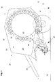
- FIG. 1 shows a round baler 10 for producing a press product in the manner of a bale 12.
- the baler shown is designed in the manner of a round baler and can both in the agricultural and in the industrial field for producing a commonly referred to as round bales, especially round cylindrical bale of crop, but also from garbage, paper, fabric or fabric, cotton, tobacco, etc. are used.
- Such a round baler 10 can be pulled by a work vehicle, not shown, preferably in the manner of a farm tractor, or designed to be self-propelled.
- the round baler 10 has a chassis 12, which is supported via an axle 14 with wheels 16 on the ground 18, a housing 20 with side walls 22, a Erntegutzuschreibvoriques 24 and a drawbar 26, by means of the round baler 10 at the work vehicle, not shown, can be connected.
- a compression chamber 28 is provided, which extends between the two side walls 22 and is surrounded by a plurality of at least substantially circular rollers 30, wherein the rollers 30, in the front region of the round baler 10, an upper gap 32nd for a binding device, not shown, and a lower gap 34 for the Erntegutzuschreibvorraum 24 left.
- a roller 30 'situated above the lower gap 34 is assigned a stripping device 36, which has a scraper carrier 38 and a scraper bar 40.
- the scraper bar 40 is adjustably fixed to the scraper carrier 38 by means of fasteners 42.
- the fastening means 42 may be in the form of screws 44, preferably of hex bolts, which hold the scratch bar 40 in the operating state at least substantially fixed to the Kratzolinnyes 38, for example by openings 45 (only hinted) penetrate in the Kratzangnany 38 and engage in one end open guide grooves 46 in the scraper rail 40 to cooperate with nuts 48, which are arranged on a screw head 50 of the screws 44 opposite side 52 of the scraper carrier 38.
- the fastening means 42 are detachably provided, preferably in the manner that the screws 44 can be solved relative to the respective nut 48. It is alternatively conceivable that the fastening means 42 cooperate with the scraper carrier 38 in such a way that the screws 44 engage in threads provided in the scraper carrier 38 (not shown).
- adjusting disks adjusting means 54 which are freely rotatably received in circular recesses 56 of the scraper bar 40; In particular, they are inserted in the scratch bar 40.
- the adjusting means 54 on the scratching bar 40 but also be rotatably mounted otherwise.
- two adjusting means 54 are provided with a circular cross-section, which is arranged in mirror symmetry with respect to a with respect to the operating direction of the round baler 10 longitudinal axis L of the scratch bar 40 each one of the guide grooves 46 are assigned accordingly.
- the adjusting means 54 are formed substantially in the manner of a flat cylinder body or disc-like and have approximately the same thickness of the scratch bar 40.
- the adjusting means 54 have penetrating oblong holes 58 which, with respect to a center M of the respective actuating means 54, assume at least substantially the shape of a screw or circular involute extending from the center M to an edge region 60 of the actuating means 54.
- the scraper bar 40 is mounted on the scraper carrier 38, one of the screws 44 'penetrates the oblong hole 56 of the associated setting disc 54.
- the scraper bar 40 can be attached to the scraper carrier 38 by means of the screw 44 engaging in the guide grooves 46 and the respective nut 48 are fixed to the scraper carrier 38. It is conceivable that in addition washers, spring washers or the like are provided.
- the adjusting discs 54 penetrating screws 44 'in turn fix the respective actuating means 54 with respect to the scraper carrier 38.
- the scraper bar 40 extends as close as possible to the rotating roller 30 'in order to scrape off adhering material and / or to prevent adhesion.
- the distance A between the scratch bar 40 and the roller 30 ' is provided adjustable.
- the scraper bar 40 will approach the roller 30 'or increase the distance A therefrom led away.
- the fastening means 42 are released, whereby the scratching bar 40 can be moved with respect to the Kratzrucnarna 38.
- the screws 44 guide the scraper bar 40 with respect to the operating direction of the round baler 10 in the longitudinal direction in the guide grooves 46th
- the adjusting means 54 and the elongated holes 58 slide in the adjusting washers 54 along the corresponding screws 44 ', whereby the adjusting washer 54 is rotated about its center M and rotates in the recess 56 in the scraper rail 40.
- the slots 58 extend from the center M of the adjusting means 54 generally eccentrically in the direction of the edge region 60 or according to the embodiment shown in the figures of the drawing in the manner of extending from the midpoint M in the direction of the edge portion 60 screw or more accurately are formed in the form of a circle involute, the rotation of one of the adjusting discs 54 results in a linear movement of the actuating means 54 and thus the scraper bar 58th
- two adjusting disks 54 are provided according to the preferred embodiment. If the scraping bar 40 is displaced, then the adjusting means 54 move at least substantially synchronously, whereby a uniform adjustment of the distance A relative to the roll 30 'over the entire width B of the scraping bar can be achieved. But it is also possible to provide only one or more actuating means 54.
- 54 attack points 62 may be provided to simplify a manual or motorized rotation of the actuating means at one or all of the adjusting means. This may be, for example, threaded nuts, in which a corresponding, not shown screw can be screwed, which can serve as an operator handle.
Landscapes
- Life Sciences & Earth Sciences (AREA)
- Environmental Sciences (AREA)
- Engineering & Computer Science (AREA)
- Mechanical Engineering (AREA)
- Preliminary Treatment Of Fibers (AREA)
- Harvesting Machines For Specific Crops (AREA)
- Storage Of Harvested Produce (AREA)
Abstract
Description
- Die vorliegende Offenbarung betrifft eine Kratzleiste für eine Abstreifereinrichtung sowie eine Abstreifervorrichtung zur Verminderung von Anhaftungen an einer mit einem Ballen zusammenwirkenden Walze einer landwirtschaftlichen Rundballenpresse. Ferner betrifft die vorliegende Offenbarung eine landwirtschaftliche Rundballenpresse zur Herstellung von Rundballen.
- Bekannte Abstreifereinrichtungen werden häufig an Rundballenpressen eingesetzt, welche bewegliche Teile aufweisen, die mit durch die Rundballenpressen zu verarbeitendem Pressgut in Berührung kommen. Die Abstreifereinrichtungen weisen Kratzleisten auf, die mit den beweglichen Teilen der Rundballenpresse zusammenwirken, um Anhaftungen von Pressgut und anderem Material, wie Schmutz, Erde, Pressgutresten etc. entgegenzuwirken, solchen vorzubeugen oder bereits bestehende Anhaftungen oder Ablagerungen zu entfernen. Bei den bewegliche Teilen handelt es sich häufig um eine oder mehrere drehbare Walzen. Es sind aber auch Abstreifereinrichtungen bekannt, die entsprechend mit Gurten bzw. Riemen einer Rundballenpresse zusammenwirken.
- Derartige Rundballenpressen werden sowohl im landwirtschaftlichen als auch industriellen Bereich eingesetzt. Entsprechende landwirtschaftliche Rundballenpressen dienen beispielsweise zur Bildung von Erntegutballen, beispielsweise in der Art von Rundballen, und erzeugen häufig zumindest im wesentlichen rundzylindrische Ballen aus Erntegut, beispielsweise in der Art von Stroh, Heu, Häckselgut etc.. Industrielle Rundballenpressen finden Verwendung bei der Verdichtung von Müll, Textilien oder anderen Stoffen bzw. bei deren Pressung zu Ballen.
- Abstreifereinrichtungen weisen üblicherweise eine Kratzleiste und einen Kratzleistenträger auf, wobei die Kratzleiste an dem Kratzleistenträger, der beispielsweise an einem Rahmen oder einem Gehäuse einer Rundballenpresse vorgesehen sein kann, durch Befestigungsmittel, beispielsweise in der Art von Verschraubungen, gehalten wird. Da Kratzleisten üblicherweise vorgesehen sind, um Anhaftungen von beweglichen Teilen, wie Walzen oder Riemen, zu entfernen oder auch um einem Aufbauen von Anhaftungen vorzubeugen bzw. entgegenzuwirken, ist zwischen der Walze und der Kratzleiste ein für diese Aufgabe geeigneter und üblicherweise möglichst geringer Abstand vorzusehen. Nutzt sich die Kratzleiste während des Einsatzes ab, verändern sich die Maschineneinstellungen und/oder die Erntebedingungen oder wird eine andere oder neue Kratzleiste montiert, so kann es notwendig sein, diesen Abstand zu verändern bzw. einzustellen. Um eine möglichst gute Funktion der Kratzleiste zu gewährleisten, sollte der Abstand der Kratzleiste zu der Walze möglichst über die gesamte Breite zumindest in etwa gleich weit sein. Es ist hierzu bekannt, die die Kratzleiste und den Kratzleistenträger verbindenden Befestigungsmittel, welche üblicherweise in der Art von Verschraubungen ausgeführt sind, zu lösen und die Kratzleiste zu verschieben. Eine derartige Einstellung ist aufwändig und kann mehrfaches Nachstellen erfordern.
- Eine zu lösende Aufgabe wird darin gesehen, eine Kratzleiste, eine Abstreifereinrichtung und eine entsprechende landwirtschaftliche Rundballenpresse der eingangs genannten Art anzugeben, durch welche die vorgenannten Nachteile überwunden werden.
- Die Aufgabe wird durch die Lehre der Patentansprüche 1, 5 bzw. 8 gelöst. Weitere vorteilhafte Ausgestaltungen und Weiterbildungen gehen aus den Unteransprüchen hervor.
- Es wird eine Kratzleiste für eine Abstreifereinrichtung offenbart, mit wenigstens einem drehbaren Stellmittel zur linearen Verstellung der Kratzleiste gegenüber einem Kratzleistenträger einer Abstreifereinrichtung, wobei die Kratzleiste wenigstens eine sich im Wesentlichen in der Verstellrichtung der Kratzleiste erstreckende Führungsnut aufweist, in der ein stationäres Führungsmittel derart aufnehmbar ist, dass sich die Kratzleiste gegenüber dem Führungsmittel verschieben lässt. Weist eine Kratzleiste für eine zuvor beschriebene Abstreifereinrichtung ein drehbares Stellmittel zur linearen Führung der Kratzleiste gegenüber dem Kratzleistenträger auf, so kann dies eine Verstellung bzw. Einstellung der Kratzleiste vereinfachen. Das Stellmittel ist mit Bezug auf die Kratzleiste drehbar gelagert, vorzugsweise in einer Aussparung der Kratzleiste drehbar aufgenommen.
- Zur Unterstützung einer gleichmäßigen Verstellung kann das Stellmittel Mittel zur Verstellung der Kratzleiste entlang einer exzentrischen Führungsbahn aufweisen. Die exzentrische Führungsbahn kann sich schneckenförmig, insbesondere zumindest annähernd kreisevolvent von einem Bereich zumindest nahe einem Mittelpunkt M des Stellmittels in Richtung eines Randbereichs des Stellmittels erstrecken oder auch durch ein Langloch bestimmt werden. Auf diese Weise kann eine gleichmäßige Bewegung der Kratzleiste und somit eine einfache Abstandseinstellung von Kratzleiste und beweglichem Bauteil erreicht bzw. unterstützt werden.
- Besonders günstig ist es, wenn das Stellmittel mit Bezug auf die Kratzleiste drehbar gelagert ist, wobei das Stellmittel in einer Aussparung der Kratzleiste drehbar aufgenommen wird. Dabei kann das Stellmittel in der Form einer Stellscheibe mit einem kreisförmigen Querschnitt und/oder einer im Wesentlichen einer Dicke der Kratzleiste entsprechenden Dicke ausgeführt sein.
- Vorzugsweise sind zumindest zwei Stellmittel vorgesehen, welche spiegelsymmetrisch zu einer Längsachse (L) der Kratzleiste angeordnet sind. Im Hinblick auf eine gleichmäßige Führung der Kratzleiste über ihre gesamt Breite bzw. zur gleichmäßigen Verstellung eines Abstands bzw. Spalts zwischen der Kratzleiste und dem beweglichen Bauteil ist es besonders günstig, zwei oder mehr Stellmittel vorzusehen.
- Eine Abstreifereinrichtung zur Verminderung von Anhaftungen an einem beweglichen Bauteil einer landwirtschaftlichen Rundballenpresse, insbesondere einer mit einem Ballen zusammenwirkenden Walze, weist eine Kratzleiste, einen Kratzleistenträger und wenigstens ein Befestigungsmittel zur Verbindung der Kratzleiste mit dem Kratzleistenträger auf. Ist darüber hinaus wenigstens ein drehbares Stellmittel vorgesehen, das geeignet ist, die Kratzleiste gegenüber dem Kratzleistenträger linear zu führen, so kann in einfacher Art und Weise eine möglichst kontrollierte lineare Verstellung der Kratzleiste mit Bezug auf die Abstreifereinrichtung bzw. den Kratzleistenträger erzielt und ein Abstand zwischen der Kratzleiste und dem beweglichen Bauteil eingestellt werden. Es ist denkbar, dass hierzu das Stellmittel gedreht und durch die Drehung des Stellmittels eine lineare Bewegung der Kratzleiste bewirkt wird. Es ist aber auch möglich, dass eine Bewegung der Kratzleiste durch das drehbare Stellmittel linear geführt wird. Ist ein zumindest im Wesentlichen stationäres Führungsmittel vorgesehen, welches in einer sich zumindest im Wesentlichen in einer Verstellrichtung der Kratzleiste erstreckenden Führungsnut verschiebbar aufgenommen wird, so kann die Drehführung des Stellmittels in einfacher Weise mit einer Linearführung des Führungsmittels überlagert werden, um so eine kontrollierte Bewegung der Kratzleiste zu erreichen, so dass sich die Kratzleiste gegenüber dem stationären Führungsmittel verschieben lässt, wobei durch Verdrehen des wenigstens einen drehbaren Stellmittels die Kratzleiste gegenüber dem Kratzleistenträger linear verstellt wird. Eine Verstellung ist sowohl manuell als auch motorisch möglich, auch eine automatische Verstellung ist denkbar. Das bewegliche Bauteil kann beispielsweise eine vorzugsweise drehbare Walze sein. Es ist aber auch denkbar, dass es sich um ein beispielsweise umlaufendes Bauteil, wie einen Gurt oder einen Riemen handelt. Auch andere Ausbildungen des beweglichen Bauteils sind denkbar.
- Ist ein mit dem Stellmittel zusammenwirkendes Führungsmittel vorgesehen, so kann dies vorzugsweise zumindest im Wesentlichen stationär an dem Kratzleistenträger bzw. der Kratzleiste vorgesehen sein. Das Führungsmittel wird vorzugsweise durch das Befestigungsmittel, insbesondere durch eine die Kratzleiste mit dem Kratzleistenträger verbindende Schraube bestimmt, wodurch die Anzahl an Bauteilen gering gehalten werden kann Es ist aber auch denkbar, ein derartiges Führungsmittel unabhängig von dem Befestigungsmittel, beispielsweise in der Art eines an der Kratzleiste bzw. dem Kratzleistenträger fest oder lösbar, beispielsweise mittels eines Gewinde, angebrachten Stifts vorzusehen.
- Es ist denkbar, dass das Stellmittel mit Bezug auf die Kratzleiste bzw. den Kratzleistenträger drehbar gelagert ist. Wird das Stellmittel aber in einer Aussparung der Kratzleiste drehbar aufgenommen, so sind keine weiteren Befestigungsmittel notwendig. Das Stellmittel kann vielmehr in einfacher Art und Weise während eines Zusammenbaus der Abstreifereinrichtung oder auch bei einer Montage einer Kratzleiste an dem Kratzleistenträger in eine Aussparung in der Kratzleiste eingelegt werden. Optional ist es aber auch denkbar, Sicherungsmittel vorzusehen, welche beispielsweise einem Herausfallen der Stellscheibe während einer Montage entgegenwirken können. Besonders günstig im Hinblick auf eine drehbare Aufnahme des Führungsmittels ist es, dieses in der Art einer Stellscheibe mit einem im Wesentlichen kreisförmigen Querschnitt auszubilden. Weist das Stellmittel bzw. die Stellscheibe alternativ oder auch darüber hinaus eine zumindest im Wesentlichen der Dicke der Kratzleiste entsprechende Dicke auf, so kann es sich in die Kratzleiste einfügen und beispielsweise Verschmutzungen bzw. Verschleiß eine verringerte Angriffsfläche bieten.
- Im Hinblick auf eine gleichmäßige Führung der Kratzleiste über ihre gesamt Breite bzw. zur gleichmäßigen Verstellung eines Abstands bzw. Spalts zwischen der Kratzleiste und dem beweglichen Bauteil ist es besonders günstig, zwei oder mehr Stellmittel vorzusehen. Eine besonders gleichmäßige Führung kann erzielt werden, wenn diese Stellmittel zumindest im Wesentlichen spiegelsymmetrisch zu einer Längsachse der Abstreifereinrichtung bzw. der Kratzleiste bezogen auf die Einsatzrichtung der Rundballenpresse angeordnet sind. Auf diese Weise kann auch einem Verkanten entgegengewirkt werden.
- Vorzugsweise weist die Kratzleiste eine sich zumindest im Wesentlichen in der Verstellrichtung der Kratzleiste erstreckende Führungsnut auf, in der ein zumindest im Wesentlichen stationäres Führungsmittels verschiebbar aufgenommen werden kann.
- Vorzugsweise weist das Stellmittel darüber hinaus Mittel zur Führung der Kratzleiste entlang einer exzentrischen Führungsbahn auf. Vorzugsweise erstreckt sich die Führungsbahn schneckenförmig, insbesondere zumindest annähernd kreisevolvent von einem Mittelpunkt M des Stellmittels in Richtung eines Randbereichs des Stellmittels und/oder wird durch ein Langloch bestimmt.
- Weist eine Rundballenpresse, vorzugsweise eine landwirtschaftliche oder industrielle Rundballenpresse zur Herstellung von Rundballen, mit wenigstens einem beweglichen Bauteil, insbesondere einer an einem Ballen angreifenden Walze, eine Abstreifereinrichtung mit den zuvor beschriebenen Merkmalen auf, so kann dies die Handhabbarkeit der Rundballenpresse verbessern, indem gegebenenfalls eine verbesserte und/oder vereinfachte Verstellung bzw. Einstellung der Kratzleiste mit Bezug auf das bewegliche Bauteil ermöglicht wird.
- Anhand der Zeichnung, die ein Ausführungsbeispiel der Erfindung zeigt, werden nachfolgend die Erfindung sowie weitere Vorteile und vorteilhafte Weiterbildungen der Erfindung und Ausgestaltungen der Erfindung näher beschrieben und erläutert.
- Es zeigt:
- Fig. 1
- eine Rundballenpresse in Seitenansicht mit einer Abstreifereinrichtung,
- Fig. 2
- eine Ansicht einer oberhalb eines unteren Spalts gelegenen Walze der Rundballenpresse gemäß
Figur 1 , mit einer der Walze zugeordneten Abstreifereinrichtung und - Fig. 3
- eine Seitenansicht der Walze und der Abstreifereinrichtung gemäß
Figur 2 . -
Figur 1 zeigt eine Rundballenpresse 10 zur Erzeugung eines Presserzeugnisses in der Art eines Ballens 12. Die gezeigte Ballenpresse ist in der Art einer Rundballenpresse ausgebildet und kann sowohl im landwirtschaftlichen als auch im industriellen Bereich zur Herstellung eines üblicherweise als Rundballen bezeichneten, insbesondere rundzylindrischen Ballens aus Erntegut , aber auch aus Müll, Papier, Stoff bzw. Gewebe, Baumwolle, Tabak etc. eingesetzt werden. Eine solche Rundballenpresse 10 kann von einem nicht gezeigten Arbeitsfahrzeug, vorzugsweise in der Art eines Ackerschleppers, gezogen werden oder auch selbstfahrend ausgebildet sein. - Die Rundballenpresse 10 weist ein Fahrgestell 12, welches sich über eine Achse 14 mit Rädern 16 auf dem Untergrund 18 abstützt, ein Gehäuse 20 mit Seitenwänden 22, eine Erntegutzufuhrvorrichtung 24 und eine Deichsel 26, mittels der die Rundballenpresse 10 an das nicht gezeigte Arbeitsfahrzeug angeschlossen werden kann, auf.
- Innerhalb des Gehäuses 20 ist eine Presskammer 28 vorgesehen, die sich zwischen den beiden Seitenwänden 22 erstreckt und von einer Vielzahl von zumindest im Wesentlichen auf einem Kreis gelegenen Walzen 30 umgeben wird, wobei die Walzen 30, im vorderen Bereich der Rundballenpresse 10 einen oberen Spalt 32 für eine nicht gezeigte Bindeeinrichtung und einen unteren Spalt 34 für die Erntegutzufuhrvorrichtung 24 belassen.
- Einer oberhalb des unteren Spalt 34 gelegenen Walze 30' ist eine Abstreifereinrichtung 36 zugeordnet, welche einen Kratzleistenträger 38 und eine Kratzleiste 40 aufweist.
- Es wird nun auch auf
Figuren 2 und3 Bezug genommen, in denen die Walze 30', der Kratzleistenträger 38 und die Kratzleiste 40 detaillierter dargestellt werden. Die Kratzleiste 40 ist an dem Kratzleistenträger 38 mittels Befestigungsmitteln 42 verstellbar festlegbar. Die Befestigungsmittel 42 können in der Art von Schrauben 44, vorzugsweise von Sechskantschrauben, ausgebildet sein, die die Kratzleiste 40 im Betriebszustand zumindest im Wesentlichen fest an dem Kratzleistenträger 38 halten, beispielsweise indem sie Öffnungen 45 (nur andeutungsweise dargestellt) in dem Kratzleistenträger 38 durchdringen und in einenends offene Führungsnuten 46 in der Kratzleiste 40 eingreifen, um mit Muttern 48 zusammenzuwirken, die auf einer einem Schraubenkopf 50 der Schrauben 44 gegenüberliegenden Seite 52 des Kratzleistenträgers 38 angeordnet sind. Zur besseren Verdeutlichung wird die bezogen aufFigur 2 rechte Schraube 44 ohne ihren vorzugsweise sechskantförmigen Schraubenkopf 50 dargestellt. Zur Veränderung bzw. Einstellung eines Abstands A zwischen der Kratzleiste 40 und der Walze 30' sind die Befestigungsmittel 42 lösbar vorgesehen, vorzugsweise in der Art, dass die Schrauben 44 bezogen auf die jeweilige Mutter 48 gelöst werden können. Es ist alternativ denkbar, dass die Befestigungsmittel 42 derart mit dem Kratzleistenträger 38 zusammenwirken, dass die Schrauben 44 in in dem Kratzleistenträger 38 vorgesehene Gewinde (nicht gezeigt) eingreifen. - Es sind darüber hinaus als Stellscheiben ausgebildete Stellmittel 54 vorgesehen, welche in kreisförmigen Aussparungen 56 der Kratzleiste 40 frei drehbar aufgenommen werden; insbesondere sind sie in die Kratzleiste 40 eingelegt. Alternativ können die Stellmittel 54 an der Kratzleiste 40 aber auch anderweitig drehbar befestigt sein. Gemäß dem in der Zeichnung dargestellten Ausführungsbeispiel sind zwei Stellmittel 54 mit kreisförmigem Querschnitt vorgesehen, welche hinsichtlich einer mit Bezug auf die Betriebsrichtung der Rundballenpresse 10 Längsachse L der Kratzleiste 40 spiegelsymmetrisch angeordnet und jeweils einer der Führungsnuten 46 entsprechend zugeordnet sind. Die Stellmittel 54 sind im Wesentlichen in der Art eines flachen Zylinderkörpers bzw. scheibenartig ausgebildet und weisen in etwa die gleiche Dicke der Kratzleiste 40 auf.
- Die Stellmittel 54 weisen sie durchdringende Langlöcher 58 auf, welche mit Bezug auf einen Mittelpunkt M des jeweiligen Stellmittels 54 zumindest im Wesentlichen die Form einer Schnecke oder Kreisevolvente annehmen, die sich von dem Mittelpunkt M zu einem Randbereich 60 des Stellmittels 54 hin erstreckt.
- Ist die Kratzleiste 40 an dem Kratzleistenträger 38 montiert, so durchdringt jeweils eine der Schrauben 44' das Langloch 56 der zugeordneten Stellscheibe 54. Wie dies bereits zuvor beschrieben wurde, kann die Kratzleiste 40 an dem Kratzleistenträger 38 mittels der in die Führungsnuten 46 eingreifenden Schraube 44 und der jeweiligen Mutter 48 an dem Kratzleistenträger 38 festgelegt werden. Es ist denkbar, dass darüber hinaus Unterlegscheiben, Federscheiben oder ähnliches vorgesehen sind. Die die Stellscheiben 54 durchdringenden Schrauben 44' legen wiederum das jeweilige Stellmittel 54 mit Bezug auf den Kratzleistenträger 38 fest.
- Im Folgenden soll nun die Funktion der Abstreifereinrichtung 36 genauer dargestellt werden:
- Die Abstreifereinrichtung 36 gemäß dem in der Zeichnung gezeigten Ausführungsbeispiel dient dazu, einer Anhaftungen von Material, wie beispielsweise Schmutz, Erntegut bzw. Erntegutreste, Erde etc. entgegenzuwirken, um auf diese Weise eine möglichst optimale Funktion der gezeigten Rundballenpresse 10 bzw. insbesondere der Walze 30' sicherzustellen. Hierdurch kann beispielsweise eine regelmäßige Bewegung des Ballens 12 und/oder eine möglichst gleichmäßig Zufuhr eines nicht dargestellten Binde- oder Umhüllungsmaterials unterstützt werden.
- Hierzu reicht die Kratzleiste 40 möglichst dicht an die rotierende Walze 30' heran, um so anhaftendes Material abzukratzen und/oder eine Anhaftung zu verhindern. Um eine möglichst gute Funktion der Abstreifereinrichtung 36 zu gewährleisten, ist der Abstand A zwischen der Kratzleiste 40 und der Walze 30' verstellbar vorgesehen.
- Soll der Abstand A verringert werden, da dieser beispielsweise durch Abnutzung der Kratzleiste 40 zu groß geworden ist oder weil sich beispielsweise die Erntebindungen verändert haben, so wird die Kratzleiste 40 an die Walze 30' heran- bzw. zu einer Vergrößerung des Abstands A von dieser weggeführt. Bei einer Montage einer neuen oder alternativen Kratzleiste 40 oder auch im Rahmen einer Wartung kann es notwendig sein, den Abstand (neu) zu justieren.
- Hierzu werden die Befestigungsmittel 42 gelöst, wodurch die Kratzleiste 40 mit Bezug auf den Kratzleistenträger 38 verschoben werden kann. Die Schrauben 44 führen die Kratzleiste 40 mit Bezug auf die Betriebsrichtung der Rundballenpresse 10 in Längsrichtung in den Führungsnuten 46.
- Zur eigentlichen Verstellung der Kratzleiste 40 mit Bezug auf den Kratzleistenträger 38 kann beispielsweise manuell an der Kratzleiste 40 und/oder an dem Stellmittel 54 angegriffen werden. Alternativ ist eine motorische und/oder automatische Verstellung denkbar.
- Wird die Kratzleiste 40 verschoben, so bewegen sich die Führungsnuten 46 in der Kratzleiste 40 entlang der in dem Kratzleistenträger 48 gehaltenen Schrauben 44. Gleichzeitig gleiten die Stellmittel 54 bzw. die Langlöcher 58 in den Stellscheiben 54 entlang der entsprechenden Schrauben 44', wodurch die Stellscheibe 54 um ihren Mittelpunkt M in Rotation versetzt wird und in der Aussparung 56 in der Kratzleiste 40 dreht. Da die Langlöcher 58 sich von dem Mittelpunkt M des Stellmittels 54 allgemein exzentrisch in Richtung des Randbereichs 60 erstrecken bzw. gemäß dem in den Figuren der Zeichnung dargestellten Ausführungsbeispiel in der Art einer sich von dem Mittelpunkt M in Richtung des Randbereichs 60 erstreckenden Schnecke bzw. genauer in Form einer Kreisevolvente ausgebildet sind, resultiert die Drehung einer der Stellscheiben 54 in einer linearen Bewegung des Stellmittels 54 und somit der Kratzleiste 58.
- Wie es in
Figur 2 dargestellt wird, sind gemäß der bevorzugten Ausführungsform zwei Stellscheiben 54 vorgesehen. Wird die Kratzleiste 40 verschoben, so bewegen sich die Stellmittel 54 zumindest im Wesentlichen synchron, wodurch eine über die gesamte Breite B der Kratzleiste gleichmäßige Verstellung des Abstands A bezogen auf die Walze 30' erzielt werden kann. Es ist aber auch möglich nur ein oder auch mehrere Stellmittel 54 vorzusehen. Darüber hinaus können an einem oder allen Stellmitteln 54 Angriffspunkte 62 zur Vereinfachung eines manuellen oder auch motorischen Drehens der Stellmittel vorgesehen sein. Hierbei kann es sich beispielsweise um Gewindemuttern handeln, in die eine entsprechende, nicht dargestellte Schraube eingeschraubt werden kann, die einer Bedienungsperson als Griff dienen kann.
Claims (8)
- Kratzleiste (40) für eine Abstreifereinrichtung (36), gekennzeichnet durch wenigstens ein drehbares Stellmittel (54) zur linearen Verstellung der Kratzleiste (40) gegenüber einem Kratzleistenträger (38) einer Abstreifereinrichtung, wobei die Kratzleiste (40) wenigstens eine sich im Wesentlichen in der Verstellrichtung der Kratzleiste (40) erstreckende Führungsnut (46) aufweist, in der ein stationäres Führungsmittel derart aufnehmbar ist, dass sich die Kratzleiste gegenüber dem Führungsmittel verschieben lässt.
- Kratzleiste (40) nach Anspruch 1, dadurch kennzeichnet, dass das Stellmittel (54) Mittel zur Verstellung der Kratzleiste (40) entlang einer exzentrischen Führungsbahn aufweist, die sich vorzugsweise schneckenförmig oder zumindest annähernd kreisevolvent von einem zumindest nahe einem Mittelpunkt M des Stellmittels (54) gelegenen Bereich in Richtung eines Randbereichs (60) des Stellmittels (54) erstreckt.
- Kratzleiste (40) nach einem der Ansprüche 1 oder 2, dadurch gekennzeichnet, dass das Stellmittel (54) mit Bezug auf die Kratzleiste (40) drehbar gelagert ist, wobei das Stellmittel (54) in einer Aussparung (56) der Kratzleiste (40) drehbar aufgenommen wird und wobei das Stellmittel (54) in der Form einer Stellscheibe mit einem kreisförmigen Querschnitt und/oder einer im Wesentlichen einer Dicke der Kratzleiste (40) entsprechenden Dicke ausgeführt ist.
- Kratzleiste (40) nach einem der Ansprüche 1 bis 3, dadurch gekennzeichnet, dass zumindest zwei Stellmittel (54) vorgesehen sind, welche vorzugsweise spiegelsymmetrisch zu einer Längsachse (L) der Kratzleiste (40) angeordnet sind.
- Abstreifereinrichtung (36) zur Verminderung von Anhaftungen an einer mit einem Ballen zusammenwirkenden Walze (30') einer landwirtschaftlichen Rundballenpresse (10), mit einer Kratzleiste (40) nach einem der Ansprüche 1 bis 4, einem Kratzleistenträger (38) und mit wenigstens einem Befestigungsmittel (42) zur Verbindung der Kratzleiste (40) mit dem Kratzleistenträger (38), wobei an dem Kratzleistenträger (38) wenigstens ein stationäres Führungsmittel angeordnet ist, welches in der Führungsnut (46) aufgenommen ist, so dass sich die Kratzleiste gegenüber dem stationären Führungsmittel verschieben lässt, wobei durch Verdrehen des wenigstens einen drehbaren Stellmittels (54) die Kratzleiste (40) gegenüber dem Kratzleistenträger (38) linear verstellt wird.
- Abstreifereinrichtung (36) nach Anspruch 5, wobei das Führungsmittel vorzugsweise durch das Befestigungsmittel (42) ausgebildet ist.
- Abstreifereinrichtung (36) nach Anspruch 6, wobei das Befestigungsmittel (42) durch eine die Kratzleiste (40) mit dem Kratzleistenträger (38) verbindende Schraube (44) ausgebildet ist.
- Landwirtschaftliche Rundballenpresse zur Herstellung von Rundballen, mit wenigstens einem beweglichen Bauteil, insbesondere einer mit einem Ballen (12) zusammenwirkenden Walze (30, 30'), gekennzeichnet durch eine Abstreifereinrichtung (36) nach einem der Ansprüche 5 bis 7.
Priority Applications (1)
| Application Number | Priority Date | Filing Date | Title |
|---|---|---|---|
| PL16179651T PL3120689T3 (pl) | 2015-07-22 | 2016-07-15 | Listwa skrobakowa, urządzenie zgarniające i rolnicza prasa zwijająca z takim urządzeniem |
Applications Claiming Priority (1)
| Application Number | Priority Date | Filing Date | Title |
|---|---|---|---|
| DE102015213854.2A DE102015213854A1 (de) | 2015-07-22 | 2015-07-22 | Kratzleiste, Abstreifereinrichtung und landwirtschaftliche Rundballenpresse mit einer solchen |
Publications (2)
| Publication Number | Publication Date |
|---|---|
| EP3120689A1 true EP3120689A1 (de) | 2017-01-25 |
| EP3120689B1 EP3120689B1 (de) | 2018-08-29 |
Family
ID=56413555
Family Applications (1)
| Application Number | Title | Priority Date | Filing Date |
|---|---|---|---|
| EP16179651.1A Active EP3120689B1 (de) | 2015-07-22 | 2016-07-15 | Kratzleiste, abstreifereinrichtung und landwirtschaftliche rundballenpresse mit einer solchen |
Country Status (5)
| Country | Link |
|---|---|
| US (1) | US10405495B2 (de) |
| EP (1) | EP3120689B1 (de) |
| BR (1) | BR102016016750B1 (de) |
| DE (1) | DE102015213854A1 (de) |
| PL (1) | PL3120689T3 (de) |
Cited By (2)
| Publication number | Priority date | Publication date | Assignee | Title |
|---|---|---|---|---|
| CN112845212A (zh) * | 2020-12-28 | 2021-05-28 | 中国科学院新疆生态与地理研究所 | 一种气象站的除冰装置及其使用方法 |
| EP4039080A1 (de) * | 2021-02-03 | 2022-08-10 | Maschinenfabrik Bernard Krone GmbH & Co. KG | Erntemaschine |
Families Citing this family (6)
| Publication number | Priority date | Publication date | Assignee | Title |
|---|---|---|---|---|
| CN109922656A (zh) | 2016-08-31 | 2019-06-21 | 维米尔制造公司 | 连续圆形打捆机和形成圆形草捆的改进方法 |
| EP3427567B1 (de) * | 2017-07-12 | 2020-03-25 | Deere & Company | Rundballenpresse |
| US10999974B2 (en) | 2019-06-10 | 2021-05-11 | Deere & Company | Plunger scraper for reciprocating baler |
| CN113734688A (zh) * | 2021-08-12 | 2021-12-03 | 安徽志昌竹木科技有限公司 | 一种竹木复合地板生产过程中的高效下料装置及其使用方法 |
| IT202200013816A1 (it) | 2022-06-30 | 2023-12-30 | Kverneland Group Ravenna Srl | Imballatore |
| IT202200013804A1 (it) | 2022-06-30 | 2023-12-30 | Kverneland Group Ravenna Srl | Imballatore |
Citations (5)
| Publication number | Priority date | Publication date | Assignee | Title |
|---|---|---|---|---|
| GB2143792A (en) * | 1983-07-27 | 1985-02-20 | Luke R F | Scraper or cleaning conveyor belts |
| US4633659A (en) * | 1984-01-27 | 1987-01-06 | Deere & Company | Cylindrical bale-forming press |
| US5191833A (en) * | 1992-04-16 | 1993-03-09 | Ford New Holland, Inc. | Roll stripping apparatus for round baler |
| DE29515629U1 (de) * | 1995-09-30 | 1995-12-07 | Maschinenfabriken Bernard Krone Gmbh, 48480 Spelle | Ballenpresse |
| CA2547896A1 (en) * | 2003-12-01 | 2005-06-16 | As Techno Track | Pre-scraper for a conveyor belt |
Family Cites Families (2)
| Publication number | Priority date | Publication date | Assignee | Title |
|---|---|---|---|---|
| US3270418A (en) * | 1964-04-21 | 1966-09-06 | Robert A Simeone | Rifle sight |
| US4436027A (en) * | 1982-04-28 | 1984-03-13 | Sperry Corporation | Stripper bar for roll baling machine |
-
2015
- 2015-07-22 DE DE102015213854.2A patent/DE102015213854A1/de not_active Withdrawn
-
2016
- 2016-07-15 EP EP16179651.1A patent/EP3120689B1/de active Active
- 2016-07-15 PL PL16179651T patent/PL3120689T3/pl unknown
- 2016-07-20 US US15/214,506 patent/US10405495B2/en active Active
- 2016-07-20 BR BR102016016750-7A patent/BR102016016750B1/pt active IP Right Grant
Patent Citations (5)
| Publication number | Priority date | Publication date | Assignee | Title |
|---|---|---|---|---|
| GB2143792A (en) * | 1983-07-27 | 1985-02-20 | Luke R F | Scraper or cleaning conveyor belts |
| US4633659A (en) * | 1984-01-27 | 1987-01-06 | Deere & Company | Cylindrical bale-forming press |
| US5191833A (en) * | 1992-04-16 | 1993-03-09 | Ford New Holland, Inc. | Roll stripping apparatus for round baler |
| DE29515629U1 (de) * | 1995-09-30 | 1995-12-07 | Maschinenfabriken Bernard Krone Gmbh, 48480 Spelle | Ballenpresse |
| CA2547896A1 (en) * | 2003-12-01 | 2005-06-16 | As Techno Track | Pre-scraper for a conveyor belt |
Cited By (2)
| Publication number | Priority date | Publication date | Assignee | Title |
|---|---|---|---|---|
| CN112845212A (zh) * | 2020-12-28 | 2021-05-28 | 中国科学院新疆生态与地理研究所 | 一种气象站的除冰装置及其使用方法 |
| EP4039080A1 (de) * | 2021-02-03 | 2022-08-10 | Maschinenfabrik Bernard Krone GmbH & Co. KG | Erntemaschine |
Also Published As
| Publication number | Publication date |
|---|---|
| EP3120689B1 (de) | 2018-08-29 |
| DE102015213854A1 (de) | 2017-01-26 |
| BR102016016750B1 (pt) | 2021-08-03 |
| BR102016016750A2 (pt) | 2017-01-24 |
| PL3120689T3 (pl) | 2019-01-31 |
| US20170020076A1 (en) | 2017-01-26 |
| US10405495B2 (en) | 2019-09-10 |
Similar Documents
| Publication | Publication Date | Title |
|---|---|---|
| EP3120689B1 (de) | Kratzleiste, abstreifereinrichtung und landwirtschaftliche rundballenpresse mit einer solchen | |
| EP1474964B1 (de) | Verfahren und Vorrichtung zur Veränderung der Durchlassöffnungen an einer Abscheidefläche, insbesondere die eines Dreschkorbes einer Erntemaschine | |
| DE69915452T2 (de) | Brechwalzeneinheit für ein Maiserntevorsatzgerät | |
| BE1027572B1 (de) | Konditionierwalzenzusammenbau | |
| DE2034579B2 (de) | In einem Schneidfeldhäcksler angeordnete Vorrichtung zum Schleifen der Messer | |
| DE102011013242B4 (de) | Ballenpresse | |
| EP3354126B1 (de) | Häckselmund und häckseltrommel für einen feldhäcksler | |
| EP2047739B1 (de) | Bandrechen | |
| EP3626044B1 (de) | Landwirtschaftliche rundballenpresse | |
| DE19910757A1 (de) | Schleifvorrichtung | |
| DE10012088A1 (de) | Vorrichtung zum Pflücken der Fruchtstände stängeliger Erntegüter | |
| EP3482625B1 (de) | Leiteinrichtung und ballenpresse | |
| DE102017008126A1 (de) | Landwirtschaftliche Arbeitsvorrichtung | |
| DE69303963T2 (de) | Verstellung der Position eines Excenters zur Steuerung Einzugsschneckenfinger | |
| EP3569056B1 (de) | Pressmittelleiteinrichtung und presse | |
| DE102014008008A1 (de) | Rundballenpresse | |
| DE69619022T2 (de) | Ballenpresse | |
| EP0014854A1 (de) | Aufnahmevorrichtung für einen Feldhäcksler | |
| DE102011013243B4 (de) | Erntemaschine | |
| DE69531465T2 (de) | Mäh- und Konditioniervorrichtung | |
| DE2923256C2 (de) | Feldhäcksler mit einer in einem Gehäuse angeordneten Schneidtrommel mit Nachschleifvorrichtung | |
| EP1738634A1 (de) | Erntegutaufnahmeeinrichtung und Erntemaschine | |
| DE102004061678B4 (de) | Förder- und/oder Schneidrotor für eine landwirtschaftliche Erntemaschine | |
| DE2730869A1 (de) | Ballenpresse | |
| DE19500795C2 (de) | Selbstfahrende Erntemaschine |
Legal Events
| Date | Code | Title | Description |
|---|---|---|---|
| PUAI | Public reference made under article 153(3) epc to a published international application that has entered the european phase |
Free format text: ORIGINAL CODE: 0009012 |
|
| STAA | Information on the status of an ep patent application or granted ep patent |
Free format text: STATUS: THE APPLICATION HAS BEEN PUBLISHED |
|
| AK | Designated contracting states |
Kind code of ref document: A1 Designated state(s): AL AT BE BG CH CY CZ DE DK EE ES FI FR GB GR HR HU IE IS IT LI LT LU LV MC MK MT NL NO PL PT RO RS SE SI SK SM TR |
|
| AX | Request for extension of the european patent |
Extension state: BA ME |
|
| STAA | Information on the status of an ep patent application or granted ep patent |
Free format text: STATUS: REQUEST FOR EXAMINATION WAS MADE |
|
| 17P | Request for examination filed |
Effective date: 20170725 |
|
| RBV | Designated contracting states (corrected) |
Designated state(s): AL AT BE BG CH CY CZ DE DK EE ES FI FR GB GR HR HU IE IS IT LI LT LU LV MC MK MT NL NO PL PT RO RS SE SI SK SM TR |
|
| RIC1 | Information provided on ipc code assigned before grant |
Ipc: B08B 1/00 20060101ALI20180116BHEP Ipc: B08B 1/02 20060101ALI20180116BHEP Ipc: A01F 15/18 20060101ALI20180116BHEP Ipc: B65G 45/12 20060101ALI20180116BHEP Ipc: A01F 15/07 20060101AFI20180116BHEP |
|
| GRAP | Despatch of communication of intention to grant a patent |
Free format text: ORIGINAL CODE: EPIDOSNIGR1 |
|
| STAA | Information on the status of an ep patent application or granted ep patent |
Free format text: STATUS: GRANT OF PATENT IS INTENDED |
|
| INTG | Intention to grant announced |
Effective date: 20180315 |
|
| GRAS | Grant fee paid |
Free format text: ORIGINAL CODE: EPIDOSNIGR3 |
|
| GRAA | (expected) grant |
Free format text: ORIGINAL CODE: 0009210 |
|
| STAA | Information on the status of an ep patent application or granted ep patent |
Free format text: STATUS: THE PATENT HAS BEEN GRANTED |
|
| AK | Designated contracting states |
Kind code of ref document: B1 Designated state(s): AL AT BE BG CH CY CZ DE DK EE ES FI FR GB GR HR HU IE IS IT LI LT LU LV MC MK MT NL NO PL PT RO RS SE SI SK SM TR |
|
| REG | Reference to a national code |
Ref country code: GB Ref legal event code: FG4D Free format text: NOT ENGLISH |
|
| REG | Reference to a national code |
Ref country code: CH Ref legal event code: EP |
|
| REG | Reference to a national code |
Ref country code: AT Ref legal event code: REF Ref document number: 1034057 Country of ref document: AT Kind code of ref document: T Effective date: 20180915 |
|
| REG | Reference to a national code |
Ref country code: IE Ref legal event code: FG4D Free format text: LANGUAGE OF EP DOCUMENT: GERMAN |
|
| REG | Reference to a national code |
Ref country code: DE Ref legal event code: R096 Ref document number: 502016001798 Country of ref document: DE |
|
| REG | Reference to a national code |
Ref country code: NL Ref legal event code: MP Effective date: 20180829 |
|
| REG | Reference to a national code |
Ref country code: LT Ref legal event code: MG4D |
|
| PG25 | Lapsed in a contracting state [announced via postgrant information from national office to epo] |
Ref country code: FI Free format text: LAPSE BECAUSE OF FAILURE TO SUBMIT A TRANSLATION OF THE DESCRIPTION OR TO PAY THE FEE WITHIN THE PRESCRIBED TIME-LIMIT Effective date: 20180829 Ref country code: NL Free format text: LAPSE BECAUSE OF FAILURE TO SUBMIT A TRANSLATION OF THE DESCRIPTION OR TO PAY THE FEE WITHIN THE PRESCRIBED TIME-LIMIT Effective date: 20180829 Ref country code: BG Free format text: LAPSE BECAUSE OF FAILURE TO SUBMIT A TRANSLATION OF THE DESCRIPTION OR TO PAY THE FEE WITHIN THE PRESCRIBED TIME-LIMIT Effective date: 20181129 Ref country code: LT Free format text: LAPSE BECAUSE OF FAILURE TO SUBMIT A TRANSLATION OF THE DESCRIPTION OR TO PAY THE FEE WITHIN THE PRESCRIBED TIME-LIMIT Effective date: 20180829 Ref country code: GR Free format text: LAPSE BECAUSE OF FAILURE TO SUBMIT A TRANSLATION OF THE DESCRIPTION OR TO PAY THE FEE WITHIN THE PRESCRIBED TIME-LIMIT Effective date: 20181130 Ref country code: NO Free format text: LAPSE BECAUSE OF FAILURE TO SUBMIT A TRANSLATION OF THE DESCRIPTION OR TO PAY THE FEE WITHIN THE PRESCRIBED TIME-LIMIT Effective date: 20181129 Ref country code: RS Free format text: LAPSE BECAUSE OF FAILURE TO SUBMIT A TRANSLATION OF THE DESCRIPTION OR TO PAY THE FEE WITHIN THE PRESCRIBED TIME-LIMIT Effective date: 20180829 Ref country code: IS Free format text: LAPSE BECAUSE OF FAILURE TO SUBMIT A TRANSLATION OF THE DESCRIPTION OR TO PAY THE FEE WITHIN THE PRESCRIBED TIME-LIMIT Effective date: 20181229 Ref country code: SE Free format text: LAPSE BECAUSE OF FAILURE TO SUBMIT A TRANSLATION OF THE DESCRIPTION OR TO PAY THE FEE WITHIN THE PRESCRIBED TIME-LIMIT Effective date: 20180829 |
|
| PG25 | Lapsed in a contracting state [announced via postgrant information from national office to epo] |
Ref country code: AL Free format text: LAPSE BECAUSE OF FAILURE TO SUBMIT A TRANSLATION OF THE DESCRIPTION OR TO PAY THE FEE WITHIN THE PRESCRIBED TIME-LIMIT Effective date: 20180829 Ref country code: HR Free format text: LAPSE BECAUSE OF FAILURE TO SUBMIT A TRANSLATION OF THE DESCRIPTION OR TO PAY THE FEE WITHIN THE PRESCRIBED TIME-LIMIT Effective date: 20180829 Ref country code: LV Free format text: LAPSE BECAUSE OF FAILURE TO SUBMIT A TRANSLATION OF THE DESCRIPTION OR TO PAY THE FEE WITHIN THE PRESCRIBED TIME-LIMIT Effective date: 20180829 |
|
| PG25 | Lapsed in a contracting state [announced via postgrant information from national office to epo] |
Ref country code: IT Free format text: LAPSE BECAUSE OF FAILURE TO SUBMIT A TRANSLATION OF THE DESCRIPTION OR TO PAY THE FEE WITHIN THE PRESCRIBED TIME-LIMIT Effective date: 20180829 Ref country code: EE Free format text: LAPSE BECAUSE OF FAILURE TO SUBMIT A TRANSLATION OF THE DESCRIPTION OR TO PAY THE FEE WITHIN THE PRESCRIBED TIME-LIMIT Effective date: 20180829 Ref country code: RO Free format text: LAPSE BECAUSE OF FAILURE TO SUBMIT A TRANSLATION OF THE DESCRIPTION OR TO PAY THE FEE WITHIN THE PRESCRIBED TIME-LIMIT Effective date: 20180829 Ref country code: CZ Free format text: LAPSE BECAUSE OF FAILURE TO SUBMIT A TRANSLATION OF THE DESCRIPTION OR TO PAY THE FEE WITHIN THE PRESCRIBED TIME-LIMIT Effective date: 20180829 Ref country code: ES Free format text: LAPSE BECAUSE OF FAILURE TO SUBMIT A TRANSLATION OF THE DESCRIPTION OR TO PAY THE FEE WITHIN THE PRESCRIBED TIME-LIMIT Effective date: 20180829 |
|
| PG25 | Lapsed in a contracting state [announced via postgrant information from national office to epo] |
Ref country code: SK Free format text: LAPSE BECAUSE OF FAILURE TO SUBMIT A TRANSLATION OF THE DESCRIPTION OR TO PAY THE FEE WITHIN THE PRESCRIBED TIME-LIMIT Effective date: 20180829 Ref country code: SM Free format text: LAPSE BECAUSE OF FAILURE TO SUBMIT A TRANSLATION OF THE DESCRIPTION OR TO PAY THE FEE WITHIN THE PRESCRIBED TIME-LIMIT Effective date: 20180829 Ref country code: DK Free format text: LAPSE BECAUSE OF FAILURE TO SUBMIT A TRANSLATION OF THE DESCRIPTION OR TO PAY THE FEE WITHIN THE PRESCRIBED TIME-LIMIT Effective date: 20180829 |
|
| REG | Reference to a national code |
Ref country code: DE Ref legal event code: R097 Ref document number: 502016001798 Country of ref document: DE |
|
| PLBE | No opposition filed within time limit |
Free format text: ORIGINAL CODE: 0009261 |
|
| STAA | Information on the status of an ep patent application or granted ep patent |
Free format text: STATUS: NO OPPOSITION FILED WITHIN TIME LIMIT |
|
| 26N | No opposition filed |
Effective date: 20190531 |
|
| PG25 | Lapsed in a contracting state [announced via postgrant information from national office to epo] |
Ref country code: SI Free format text: LAPSE BECAUSE OF FAILURE TO SUBMIT A TRANSLATION OF THE DESCRIPTION OR TO PAY THE FEE WITHIN THE PRESCRIBED TIME-LIMIT Effective date: 20180829 |
|
| PG25 | Lapsed in a contracting state [announced via postgrant information from national office to epo] |
Ref country code: MC Free format text: LAPSE BECAUSE OF FAILURE TO SUBMIT A TRANSLATION OF THE DESCRIPTION OR TO PAY THE FEE WITHIN THE PRESCRIBED TIME-LIMIT Effective date: 20180829 |
|
| REG | Reference to a national code |
Ref country code: CH Ref legal event code: PL |
|
| PG25 | Lapsed in a contracting state [announced via postgrant information from national office to epo] |
Ref country code: TR Free format text: LAPSE BECAUSE OF FAILURE TO SUBMIT A TRANSLATION OF THE DESCRIPTION OR TO PAY THE FEE WITHIN THE PRESCRIBED TIME-LIMIT Effective date: 20180829 |
|
| REG | Reference to a national code |
Ref country code: BE Ref legal event code: MM Effective date: 20190731 |
|
| PG25 | Lapsed in a contracting state [announced via postgrant information from national office to epo] |
Ref country code: LI Free format text: LAPSE BECAUSE OF NON-PAYMENT OF DUE FEES Effective date: 20190731 Ref country code: CH Free format text: LAPSE BECAUSE OF NON-PAYMENT OF DUE FEES Effective date: 20190731 Ref country code: LU Free format text: LAPSE BECAUSE OF NON-PAYMENT OF DUE FEES Effective date: 20190715 Ref country code: BE Free format text: LAPSE BECAUSE OF NON-PAYMENT OF DUE FEES Effective date: 20190731 |
|
| PG25 | Lapsed in a contracting state [announced via postgrant information from national office to epo] |
Ref country code: PT Free format text: LAPSE BECAUSE OF FAILURE TO SUBMIT A TRANSLATION OF THE DESCRIPTION OR TO PAY THE FEE WITHIN THE PRESCRIBED TIME-LIMIT Effective date: 20181229 |
|
| GBPC | Gb: european patent ceased through non-payment of renewal fee |
Effective date: 20200715 |
|
| PG25 | Lapsed in a contracting state [announced via postgrant information from national office to epo] |
Ref country code: GB Free format text: LAPSE BECAUSE OF NON-PAYMENT OF DUE FEES Effective date: 20200715 |
|
| PG25 | Lapsed in a contracting state [announced via postgrant information from national office to epo] |
Ref country code: CY Free format text: LAPSE BECAUSE OF FAILURE TO SUBMIT A TRANSLATION OF THE DESCRIPTION OR TO PAY THE FEE WITHIN THE PRESCRIBED TIME-LIMIT Effective date: 20180829 |
|
| PG25 | Lapsed in a contracting state [announced via postgrant information from national office to epo] |
Ref country code: MT Free format text: LAPSE BECAUSE OF FAILURE TO SUBMIT A TRANSLATION OF THE DESCRIPTION OR TO PAY THE FEE WITHIN THE PRESCRIBED TIME-LIMIT Effective date: 20180829 Ref country code: HU Free format text: LAPSE BECAUSE OF FAILURE TO SUBMIT A TRANSLATION OF THE DESCRIPTION OR TO PAY THE FEE WITHIN THE PRESCRIBED TIME-LIMIT; INVALID AB INITIO Effective date: 20160715 |
|
| PG25 | Lapsed in a contracting state [announced via postgrant information from national office to epo] |
Ref country code: MK Free format text: LAPSE BECAUSE OF FAILURE TO SUBMIT A TRANSLATION OF THE DESCRIPTION OR TO PAY THE FEE WITHIN THE PRESCRIBED TIME-LIMIT Effective date: 20180829 |
|
| REG | Reference to a national code |
Ref country code: AT Ref legal event code: MM01 Ref document number: 1034057 Country of ref document: AT Kind code of ref document: T Effective date: 20210715 |
|
| PG25 | Lapsed in a contracting state [announced via postgrant information from national office to epo] |
Ref country code: AT Free format text: LAPSE BECAUSE OF NON-PAYMENT OF DUE FEES Effective date: 20210715 |
|
| PGFP | Annual fee paid to national office [announced via postgrant information from national office to epo] |
Ref country code: PL Payment date: 20250618 Year of fee payment: 10 |
|
| PGFP | Annual fee paid to national office [announced via postgrant information from national office to epo] |
Ref country code: DE Payment date: 20250620 Year of fee payment: 10 |
|
| PGFP | Annual fee paid to national office [announced via postgrant information from national office to epo] |
Ref country code: FR Payment date: 20250725 Year of fee payment: 10 |
|
| PGFP | Annual fee paid to national office [announced via postgrant information from national office to epo] |
Ref country code: IE Payment date: 20250728 Year of fee payment: 10 |