EP3119623B1 - Module de chauffage et de refroidissement - Google Patents
Module de chauffage et de refroidissement Download PDFInfo
- Publication number
- EP3119623B1 EP3119623B1 EP15709918.5A EP15709918A EP3119623B1 EP 3119623 B1 EP3119623 B1 EP 3119623B1 EP 15709918 A EP15709918 A EP 15709918A EP 3119623 B1 EP3119623 B1 EP 3119623B1
- Authority
- EP
- European Patent Office
- Prior art keywords
- region
- base plate
- refrigerant
- cooling module
- heating
- Prior art date
- Legal status (The legal status is an assumption and is not a legal conclusion. Google has not performed a legal analysis and makes no representation as to the accuracy of the status listed.)
- Active
Links
- 238000001816 cooling Methods 0.000 title claims description 56
- 238000010438 heat treatment Methods 0.000 title claims description 45
- 239000003507 refrigerant Substances 0.000 claims description 121
- 239000012530 fluid Substances 0.000 claims description 115
- 239000002826 coolant Substances 0.000 claims description 68
- 238000012546 transfer Methods 0.000 claims description 60
- 238000013461 design Methods 0.000 claims description 11
- 238000004891 communication Methods 0.000 claims description 5
- 238000001035 drying Methods 0.000 claims description 4
- 238000001914 filtration Methods 0.000 claims description 3
- 239000003990 capacitor Substances 0.000 description 15
- 238000010276 construction Methods 0.000 description 7
- 238000009434 installation Methods 0.000 description 4
- 238000011161 development Methods 0.000 description 3
- 230000018109 developmental process Effects 0.000 description 3
- 238000011144 upstream manufacturing Methods 0.000 description 3
- XLYOFNOQVPJJNP-UHFFFAOYSA-N water Substances O XLYOFNOQVPJJNP-UHFFFAOYSA-N 0.000 description 3
- ATUOYWHBWRKTHZ-UHFFFAOYSA-N Propane Chemical compound CCC ATUOYWHBWRKTHZ-UHFFFAOYSA-N 0.000 description 2
- 230000000694 effects Effects 0.000 description 2
- 238000007654 immersion Methods 0.000 description 2
- 238000009413 insulation Methods 0.000 description 2
- 238000012423 maintenance Methods 0.000 description 2
- 238000005476 soldering Methods 0.000 description 2
- FXRLMCRCYDHQFW-UHFFFAOYSA-N 2,3,3,3-tetrafluoropropene Chemical compound FC(=C)C(F)(F)F FXRLMCRCYDHQFW-UHFFFAOYSA-N 0.000 description 1
- 240000001439 Opuntia Species 0.000 description 1
- 235000004727 Opuntia ficus indica Nutrition 0.000 description 1
- 150000001875 compounds Chemical class 0.000 description 1
- 238000009833 condensation Methods 0.000 description 1
- 230000005494 condensation Effects 0.000 description 1
- 238000006073 displacement reaction Methods 0.000 description 1
- 230000006872 improvement Effects 0.000 description 1
- 238000003780 insertion Methods 0.000 description 1
- 230000037431 insertion Effects 0.000 description 1
- 230000010354 integration Effects 0.000 description 1
- 238000002955 isolation Methods 0.000 description 1
- 238000003754 machining Methods 0.000 description 1
- 239000000463 material Substances 0.000 description 1
- 238000000034 method Methods 0.000 description 1
- 238000002156 mixing Methods 0.000 description 1
- 230000008569 process Effects 0.000 description 1
- 239000001294 propane Substances 0.000 description 1
- 230000009467 reduction Effects 0.000 description 1
- 230000008439 repair process Effects 0.000 description 1
- 239000007787 solid Substances 0.000 description 1
Images


Classifications
-
- B—PERFORMING OPERATIONS; TRANSPORTING
- B60—VEHICLES IN GENERAL
- B60H—ARRANGEMENTS OF HEATING, COOLING, VENTILATING OR OTHER AIR-TREATING DEVICES SPECIALLY ADAPTED FOR PASSENGER OR GOODS SPACES OF VEHICLES
- B60H1/00—Heating, cooling or ventilating [HVAC] devices
- B60H1/00321—Heat exchangers for air-conditioning devices
- B60H1/00342—Heat exchangers for air-conditioning devices of the liquid-liquid type
-
- B—PERFORMING OPERATIONS; TRANSPORTING
- B60—VEHICLES IN GENERAL
- B60H—ARRANGEMENTS OF HEATING, COOLING, VENTILATING OR OTHER AIR-TREATING DEVICES SPECIALLY ADAPTED FOR PASSENGER OR GOODS SPACES OF VEHICLES
- B60H1/00—Heating, cooling or ventilating [HVAC] devices
- B60H1/00271—HVAC devices specially adapted for particular vehicle parts or components and being connected to the vehicle HVAC unit
- B60H1/00278—HVAC devices specially adapted for particular vehicle parts or components and being connected to the vehicle HVAC unit for the battery
-
- B—PERFORMING OPERATIONS; TRANSPORTING
- B60—VEHICLES IN GENERAL
- B60H—ARRANGEMENTS OF HEATING, COOLING, VENTILATING OR OTHER AIR-TREATING DEVICES SPECIALLY ADAPTED FOR PASSENGER OR GOODS SPACES OF VEHICLES
- B60H1/00—Heating, cooling or ventilating [HVAC] devices
- B60H1/00485—Valves for air-conditioning devices, e.g. thermostatic valves
-
- B—PERFORMING OPERATIONS; TRANSPORTING
- B60—VEHICLES IN GENERAL
- B60H—ARRANGEMENTS OF HEATING, COOLING, VENTILATING OR OTHER AIR-TREATING DEVICES SPECIALLY ADAPTED FOR PASSENGER OR GOODS SPACES OF VEHICLES
- B60H1/00—Heating, cooling or ventilating [HVAC] devices
- B60H1/00507—Details, e.g. mounting arrangements, desaeration devices
- B60H1/00557—Details of ducts or cables
- B60H1/00571—Details of ducts or cables of liquid ducts, e.g. for coolant liquids or refrigerants
-
- B—PERFORMING OPERATIONS; TRANSPORTING
- B60—VEHICLES IN GENERAL
- B60H—ARRANGEMENTS OF HEATING, COOLING, VENTILATING OR OTHER AIR-TREATING DEVICES SPECIALLY ADAPTED FOR PASSENGER OR GOODS SPACES OF VEHICLES
- B60H1/00—Heating, cooling or ventilating [HVAC] devices
- B60H1/00642—Control systems or circuits; Control members or indication devices for heating, cooling or ventilating devices
- B60H1/00814—Control systems or circuits characterised by their output, for controlling particular components of the heating, cooling or ventilating installation
- B60H1/00878—Control systems or circuits characterised by their output, for controlling particular components of the heating, cooling or ventilating installation the components being temperature regulating devices
- B60H1/00899—Controlling the flow of liquid in a heat pump system
-
- B—PERFORMING OPERATIONS; TRANSPORTING
- B60—VEHICLES IN GENERAL
- B60H—ARRANGEMENTS OF HEATING, COOLING, VENTILATING OR OTHER AIR-TREATING DEVICES SPECIALLY ADAPTED FOR PASSENGER OR GOODS SPACES OF VEHICLES
- B60H1/00—Heating, cooling or ventilating [HVAC] devices
- B60H1/32—Cooling devices
- B60H1/3204—Cooling devices using compression
- B60H1/3227—Cooling devices using compression characterised by the arrangement or the type of heat exchanger, e.g. condenser, evaporator
-
- B—PERFORMING OPERATIONS; TRANSPORTING
- B60—VEHICLES IN GENERAL
- B60H—ARRANGEMENTS OF HEATING, COOLING, VENTILATING OR OTHER AIR-TREATING DEVICES SPECIALLY ADAPTED FOR PASSENGER OR GOODS SPACES OF VEHICLES
- B60H1/00—Heating, cooling or ventilating [HVAC] devices
- B60H1/32—Cooling devices
- B60H1/3204—Cooling devices using compression
- B60H1/3228—Cooling devices using compression characterised by refrigerant circuit configurations
- B60H1/32284—Cooling devices using compression characterised by refrigerant circuit configurations comprising two or more secondary circuits, e.g. at evaporator and condenser side
-
- B—PERFORMING OPERATIONS; TRANSPORTING
- B60—VEHICLES IN GENERAL
- B60H—ARRANGEMENTS OF HEATING, COOLING, VENTILATING OR OTHER AIR-TREATING DEVICES SPECIALLY ADAPTED FOR PASSENGER OR GOODS SPACES OF VEHICLES
- B60H1/00—Heating, cooling or ventilating [HVAC] devices
- B60H1/32—Cooling devices
- B60H1/3204—Cooling devices using compression
- B60H1/3229—Cooling devices using compression characterised by constructional features, e.g. housings, mountings, conversion systems
-
- F—MECHANICAL ENGINEERING; LIGHTING; HEATING; WEAPONS; BLASTING
- F25—REFRIGERATION OR COOLING; COMBINED HEATING AND REFRIGERATION SYSTEMS; HEAT PUMP SYSTEMS; MANUFACTURE OR STORAGE OF ICE; LIQUEFACTION SOLIDIFICATION OF GASES
- F25B—REFRIGERATION MACHINES, PLANTS OR SYSTEMS; COMBINED HEATING AND REFRIGERATION SYSTEMS; HEAT PUMP SYSTEMS
- F25B39/00—Evaporators; Condensers
-
- F—MECHANICAL ENGINEERING; LIGHTING; HEATING; WEAPONS; BLASTING
- F25—REFRIGERATION OR COOLING; COMBINED HEATING AND REFRIGERATION SYSTEMS; HEAT PUMP SYSTEMS; MANUFACTURE OR STORAGE OF ICE; LIQUEFACTION SOLIDIFICATION OF GASES
- F25B—REFRIGERATION MACHINES, PLANTS OR SYSTEMS; COMBINED HEATING AND REFRIGERATION SYSTEMS; HEAT PUMP SYSTEMS
- F25B40/00—Subcoolers, desuperheaters or superheaters
- F25B40/02—Subcoolers
-
- F—MECHANICAL ENGINEERING; LIGHTING; HEATING; WEAPONS; BLASTING
- F25—REFRIGERATION OR COOLING; COMBINED HEATING AND REFRIGERATION SYSTEMS; HEAT PUMP SYSTEMS; MANUFACTURE OR STORAGE OF ICE; LIQUEFACTION SOLIDIFICATION OF GASES
- F25B—REFRIGERATION MACHINES, PLANTS OR SYSTEMS; COMBINED HEATING AND REFRIGERATION SYSTEMS; HEAT PUMP SYSTEMS
- F25B43/00—Arrangements for separating or purifying gases or liquids; Arrangements for vaporising the residuum of liquid refrigerant, e.g. by heat
- F25B43/003—Filters
-
- F—MECHANICAL ENGINEERING; LIGHTING; HEATING; WEAPONS; BLASTING
- F28—HEAT EXCHANGE IN GENERAL
- F28D—HEAT-EXCHANGE APPARATUS, NOT PROVIDED FOR IN ANOTHER SUBCLASS, IN WHICH THE HEAT-EXCHANGE MEDIA DO NOT COME INTO DIRECT CONTACT
- F28D9/00—Heat-exchange apparatus having stationary plate-like or laminated conduit assemblies for both heat-exchange media, the media being in contact with different sides of a conduit wall
- F28D9/0093—Multi-circuit heat-exchangers, e.g. integrating different heat exchange sections in the same unit or heat-exchangers for more than two fluids
-
- F—MECHANICAL ENGINEERING; LIGHTING; HEATING; WEAPONS; BLASTING
- F28—HEAT EXCHANGE IN GENERAL
- F28F—DETAILS OF HEAT-EXCHANGE AND HEAT-TRANSFER APPARATUS, OF GENERAL APPLICATION
- F28F3/00—Plate-like or laminated elements; Assemblies of plate-like or laminated elements
- F28F3/08—Elements constructed for building-up into stacks, e.g. capable of being taken apart for cleaning
-
- H—ELECTRICITY
- H01—ELECTRIC ELEMENTS
- H01M—PROCESSES OR MEANS, e.g. BATTERIES, FOR THE DIRECT CONVERSION OF CHEMICAL ENERGY INTO ELECTRICAL ENERGY
- H01M10/00—Secondary cells; Manufacture thereof
- H01M10/60—Heating or cooling; Temperature control
-
- H—ELECTRICITY
- H01—ELECTRIC ELEMENTS
- H01M—PROCESSES OR MEANS, e.g. BATTERIES, FOR THE DIRECT CONVERSION OF CHEMICAL ENERGY INTO ELECTRICAL ENERGY
- H01M10/00—Secondary cells; Manufacture thereof
- H01M10/60—Heating or cooling; Temperature control
- H01M10/62—Heating or cooling; Temperature control specially adapted for specific applications
- H01M10/625—Vehicles
-
- H—ELECTRICITY
- H01—ELECTRIC ELEMENTS
- H01M—PROCESSES OR MEANS, e.g. BATTERIES, FOR THE DIRECT CONVERSION OF CHEMICAL ENERGY INTO ELECTRICAL ENERGY
- H01M10/00—Secondary cells; Manufacture thereof
- H01M10/60—Heating or cooling; Temperature control
- H01M10/65—Means for temperature control structurally associated with the cells
- H01M10/655—Solid structures for heat exchange or heat conduction
- H01M10/6556—Solid parts with flow channel passages or pipes for heat exchange
-
- F—MECHANICAL ENGINEERING; LIGHTING; HEATING; WEAPONS; BLASTING
- F25—REFRIGERATION OR COOLING; COMBINED HEATING AND REFRIGERATION SYSTEMS; HEAT PUMP SYSTEMS; MANUFACTURE OR STORAGE OF ICE; LIQUEFACTION SOLIDIFICATION OF GASES
- F25B—REFRIGERATION MACHINES, PLANTS OR SYSTEMS; COMBINED HEATING AND REFRIGERATION SYSTEMS; HEAT PUMP SYSTEMS
- F25B2339/00—Details of evaporators; Details of condensers
- F25B2339/04—Details of condensers
- F25B2339/047—Water-cooled condensers
-
- F—MECHANICAL ENGINEERING; LIGHTING; HEATING; WEAPONS; BLASTING
- F25—REFRIGERATION OR COOLING; COMBINED HEATING AND REFRIGERATION SYSTEMS; HEAT PUMP SYSTEMS; MANUFACTURE OR STORAGE OF ICE; LIQUEFACTION SOLIDIFICATION OF GASES
- F25B—REFRIGERATION MACHINES, PLANTS OR SYSTEMS; COMBINED HEATING AND REFRIGERATION SYSTEMS; HEAT PUMP SYSTEMS
- F25B25/00—Machines, plants or systems, using a combination of modes of operation covered by two or more of the groups F25B1/00 - F25B23/00
- F25B25/005—Machines, plants or systems, using a combination of modes of operation covered by two or more of the groups F25B1/00 - F25B23/00 using primary and secondary systems
-
- Y—GENERAL TAGGING OF NEW TECHNOLOGICAL DEVELOPMENTS; GENERAL TAGGING OF CROSS-SECTIONAL TECHNOLOGIES SPANNING OVER SEVERAL SECTIONS OF THE IPC; TECHNICAL SUBJECTS COVERED BY FORMER USPC CROSS-REFERENCE ART COLLECTIONS [XRACs] AND DIGESTS
- Y02—TECHNOLOGIES OR APPLICATIONS FOR MITIGATION OR ADAPTATION AGAINST CLIMATE CHANGE
- Y02E—REDUCTION OF GREENHOUSE GAS [GHG] EMISSIONS, RELATED TO ENERGY GENERATION, TRANSMISSION OR DISTRIBUTION
- Y02E60/00—Enabling technologies; Technologies with a potential or indirect contribution to GHG emissions mitigation
- Y02E60/10—Energy storage using batteries
Definitions
- the invention relates to a Walkerksselmodul for controlling the temperature of at least two coolant circuits, with an evaporator region and a condenser region, wherein the evaporator region has a first flow path, which is flowed through by a first coolant, and the condenser region has a second flow path, which can be flowed through by a second coolant is, and wherein the Schuksselmodul has a third flow path, which is traversed by a refrigerant.
- evaporators are used regularly to cool the interior. Furthermore, capacitors are used, which deliver the heat to the outside air. Regularly additional components are added to the refrigerant circuits to realize further functionalities. This happens, for example, to allow the heating of the interior or additionally built-in batteries to cool. This is increasingly the case in particular with electrically driven vehicles in order to operate the batteries required for the drive in an optimum temperature window.
- the refrigerant circuit may be connected to a warm and a cold water-glysantin cycle.
- the heat can be decoupled as desired via air-water heat exchangers.
- a chiller serves in particular the cooling of a medium flowing around the chiller.
- a circuit produced in this way can thus consist of a chiller, a condenser, a thermostatic expansion valve (TXV) and a compressor.
- TXV thermostatic expansion valve
- a collector may be provided to compensate for fluid fluctuations.
- a water-side subcooling region or an internal heat exchanger may be provided in order to bring about an improvement in the efficiency.
- a disadvantage of the known in the prior art solutions is that the large number of elements used causes a high space requirement. Furthermore, a plurality of connecting lines must be provided to connect the individual elements together. These compounds increase the assembly costs and represent an additional source of error. Furthermore, it is disadvantageous that in previously known solutions, which are formed by a combination of several heat exchanger elements in a structural unit, no internal heat exchanger or chiller are integrated.
- An embodiment of the invention relates to a Walkerksselmodul for controlling the temperature of at least two coolant circuits, with an evaporator region and a condenser region, wherein the evaporator region has a first flow path, which is traversed by a first coolant, and the condenser region has a second flow path, which of a second Coolant is flowed through, and wherein the Edelkühlmodul has a third flow path, which is traversed by a refrigerant, wherein the evaporator region and the condenser region are arranged on a common base plate, which the fluid inlets and the fluid drains for the first coolant, the second coolant and the refrigerant wherein the base plate has flow channels, each of which can be flowed through by one of the coolant or the refrigerant, wherein the evaporator region and the condenser region via the Strömungsk in fluid communication with the respective fluid inlets and the respective fluid outlets of the baseplate.
- a common base plate is particularly advantageous, since on the one hand increases the stability of the entire Schuksselmoduls and on the other hand is conducive to a compact design. It is particularly advantageous if the base plate at the same time has the required fluid supplies and the required fluid flows and also means which are adapted to direct the refrigerant and the coolant to the respective heat transfer elements.
- the base plate can thus replace a plurality of connection lines, which for the fluid supply of the individual heat transfer elements would be necessary. This also reduces the required volume of fluid, since the supply and discharge lines are much shorter and thus have a lower internal volume.
- a Walkerkühlmodul invention provides a modular structure, which allows to represent different configurations of the various heat transfer elements on a base plate.
- the heating cooling module can thus be easily adapted to different requirements.
- a large number of equal components can be used. Overall, a higher flexibility is achieved by the structure according to the invention.
- the third flow path is in particular traversed by a refrigerant.
- This flow path can extend along the entire Schukühlmoduls by a plurality of heat exchanger elements. In particular, it extends through both the evaporator region and the condenser region. There takes place between the refrigerant which flows through the third flow path, and in each case either the first coolant or the second coolant, a heat transfer.
- thermostatic expansion valve is arranged on or in the base plate, which can be flowed through by the refrigerant.
- the expansion valve which is used to expand the refrigerant, may preferably be arranged directly on or inside the base plate. This further leads to a more compact construction and in addition to a mechanical Protection of the expansion valve by the walls delimiting the base plate.
- the expansion valve is preferably again releasably integrated on or in the base plate.
- a collector is arranged on or in the base plate, which is used for collection and / or storage and / or for filtering and / or drying of the refrigerant.
- a collector is particularly advantageous in order to compensate for volume fluctuations of the refrigerant over the service life. Also, as long as possible constant quality of the refrigerant can be achieved in the refrigerant circuit by a collector with filter means and / or drying means.
- a preferred embodiment is characterized in that an inner heat exchanger and / or a sub-cooling region is arranged on the base plate, wherein the inner heat exchanger and / or the sub-cooling region are also in fluid communication with flow channels of the base plate and can be flowed through.
- An internal heat exchanger is advantageous in order to achieve a further heat transfer between the refrigerant which has flowed through the evaporator region and the refrigerant which has flowed through the condenser region. Such additional heat transfer additionally increases the efficiency of the Schukühlmoduls.
- a subcooling region is advantageous in order to achieve a further cooling of the refrigerant below the condensation temperature. By still further cooled refrigerant can be increased overall the efficiency.
- both an internal heat exchanger and a subcooling area can be provided.
- only one of the two heat exchanger elements can be provided.
- the fluidic connection to flow channels or line structures within the base plate are also advantageous in order to achieve a compact design of the Schuksselmoduls.
- the base plate as a connection element and distribution element can be reduced in total the number of joints in the refrigerant circuit and in the coolant circuit, which increases the robustness of the system.
- the flow path through which the refrigerant flows must preferably be connected only to the compressor of the refrigerant circuit.
- the compact design allows the Schuksselmodul can be placed in a particularly safe area, which prevents damage to the Schuksselmoduls in the event of an accident, or at least significantly reduces the likelihood of damage. This is particularly advantageous when a combustible refrigerant is used.
- the heating cooling module may be used for the use of R-134a, R-1234yf or other so-called low pressure refrigerants.
- propane can be provided for this purpose.
- the Schuksselmodul also for high pressure refrigerant, such as R-744, usable.
- a so-called gas cooler is then provided.
- the evaporator region and / or the condenser region and / or the inner heat exchanger and / or the subcooling region and / or the collector are constructed in stacking disk construction by stacking several disk elements one upon the other.
- the aforementioned heat transfer elements are constructed in a stacked disk design. This is advantageous to achieve a simple construction. Heat exchanger elements produced in stacked disk construction can be produced inexpensively, since a multiplicity of identical parts can be used. Furthermore, they are easily scalable and thus adaptable to the respective expected load.
- the heat transfer elements arranged on the base plate are arranged adjacent to one another in an direction transverse to the stacking direction of one of the disk stacks on an outer surface of the base plate.
- a mutually adjacent arrangement on a common outer surface of the base plate is advantageous in order to achieve a compact design.
- a thermal isolation of the individual heat exchanger elements to each other can be achieved by the spacing.
- the arrangement on a common outer surface is advantageous since the supply and discharge lines can then also be arranged on a common outer surface.
- the space available regularly for such Walkerkühlmodul space can be better utilized overall.
- the condenser region and / or the evaporator region and / or the collector and / or the inner heat exchanger and / or the subcooling region is formed by common disk elements, the individual heat exchanger elements being fluidly separated from one another by separating elements in the respective disk elements.
- a Schukühlmodul with common disk elements for the individual heat exchanger elements may be advantageous because the different heat exchanger elements can be produced in a common step.
- separating elements are preferably provided in the interior of the common disk stack.
- thermal insulation elements can also be provided within the common disk stack.
- the base plate has flow channels through which heat exchanger elements which are not arranged directly adjacent to one another can be fluidly connected to one another.
- Flow channels within the base plate are advantageous in order to fluidically connect to each other not directly adjacent heat transfer elements.
- the base plate is designed in several parts, wherein the flow channels are arranged in the interior of the base plate and are covered by a cover or more cover elements to the outside.
- the base plate may for example be formed by a box-shaped structure, in which insert elements are provided, through which the flow channels are formed in the interior of the base plate.
- the box-shaped structure can be closed in a fluid-tight manner via a cover element.
- the box-shaped structure, the insertion elements and the cover can be permanently connected to each other.
- the flow channels can also be produced by a machining process from a solid body. The flow channels can then be closed by cover elements.
- the base plate fulfills a function of its structure, which is modeled on the boards in electrical circuits. On the one hand, it serves as a carrier element for the heat exchanger elements and furthermore as a connection means, which holds the flow channels ready to produce a fluidic connection. Analogous to a classic circuit board, the flow channels can also be used in several levels be formed within the base plate or extend on one of its outer surfaces.
- the fluid inlets and the fluid outlets are arranged on a common outer surface of the baseplate. This is particularly advantageous in order to achieve the most compact possible design of the heating cooling module and to allow easy access to the fluid feeds and fluid drains in the event of maintenance or repair.
- the outer surface of the base plate which has the fluid inlets and the fluid outlets, faces the outer surface on which the heat exchanger elements are arranged. This is particularly advantageous in order to achieve a compact design of the Schukühlmoduls.
- a direct passage of a fluid through the base plate into one of the heat transfer elements can be achieved in this way, without the fluid must be additionally redirected. As a result, the occurring pressure loss is reduced in Walkerksselmodul, whereby the overall efficiency can be increased.
- a further exemplary embodiment is characterized in that the individual heat exchanger elements have different external dimensions and / or different internal volumes. This is particularly advantageous in order to better adapt the individual heat exchanger to the loads occurring. In this case, in particular the respectively necessary heat transfer is relevant as a parameter for the dimensioning.
- the internal volume can be achieved in particular that the circulating in Walkerkühlmodul amount of fluid is as low as possible.
- the base plate has positioning elements which form a receiving region for at least one of the heat transfer elements.
- Positioning elements may be, for example, depressions and / or elevations, which make it possible to position an already pre-assembled heat transfer element or the base plate of the heat transfer element relative to the base plate, that a simplified alignment between the fluid openings of the base plate and the corresponding fluid openings of the respective heat transfer element is enabled. This simplifies the overall assembly, which costs can be saved.
- the Fig. 1 to 17 each show a schematic view of a Walkerkyermoduls 1.
- All shown Schuksselmodule 1 each have a first fluid inlet 6 and a first fluid outlet 7, through which a coolant can flow into the Schukühlmodul 1 and can flow out of this.
- the condenser region 2 of the heating cooling module 1 is flowed through.
- all Thompsonkschreibmodule 1 a second fluid inlet 8 and a second fluid outlet 9, through which also a coolant can flow in and out again, whereby mainly the evaporator portion 3 of the Bankksselmoduls 1 flows through this coolant.
- the flow path 13 designates the flow path of the coolant in the condenser region 2.
- the flow path 14 designates the flow path of the coolant within the evaporator region 3.
- the flow path 12 designates the flow path of the refrigerant between the third fluid inlet 10 and the third fluid outlet 11.
- the flow path 12 extends regularly through the evaporator section 3 and the condenser section 2.
- Fig. 1 to 17 each have a designated by the reference numeral 5 expansion valve. This is in each case integrated into the flow path 12 of the refrigerant and is respectively disposed on or in the Schuksselmodul 1.
- This expansion valve 5 corresponds to a regular expansion valve as used in refrigerant circuits in other prior art solutions.
- the expansion valve 5 can preferably be subsequently used in the Schuksselmodul 1 and bolted to the Schuksselmodul 1 or simply plugged.
- the heating cooling module 1 has a plurality of heat transfer elements.
- the evaporator area, the condenser area, the collector, the internal heat exchanger or a subcooling area can count.
- at least one evaporator region and one condenser region are provided.
- the remaining heat exchanger elements can be provided, but need not necessarily be provided.
- FIG. 1 to 17 show different arrangement principles of the individual heat exchanger elements to each other. Moreover, in the Fig. 1 to 17 each one possible embodiment of the flow paths 12, 13 and 14 represented by the Schukühlmodule 1.
- the individual heat exchanger elements can not, as shown, be arranged in a common block, but in individual individual areas and spaced from each other.
- the individual heat exchanger elements are arranged on a common base plate, which forms a plurality of flow channels and further comprises the fluid inlets and the fluid drains for the coolant and the refrigerant.
- the base plate is shown inter alia by the areas 4, 18 and 19, which in the Fig. 1 to 17 are shown.
- the supply and discharge of coolant and / or refrigerant between the individual heat transfer elements is achieved by the flow channels in the base plate.
- immersion sleeves or other piping may be provided which can fluidly connect the individual heat transfer elements together.
- the Fig. 1 to 17 serve in particular to give an overview of the possible arrangement forms and in particular about the ranking of the individual heat exchanger elements.
- a capacitor region 2 is arranged in the left region and an evaporator region 3 in the right region.
- the two regions 2, 3 are arranged spatially separated from one another, so that in the Fig. 1 the view of the area 4 of the base plate falls.
- the heat transfer elements are arranged on this common base plate.
- the Fig. 1 to 17 each show a plan view of the outer surface of the base plate, which has the heat transfer elements.
- the fluid inlets and the fluid outlets 6 to 11 are in each case preferably arranged on the outer surface of the base plate facing away from the observer.
- the capacitor region 2 simply flows through in a U-shaped form. That is, there is no further deflection within the capacitor region 2.
- the evaporator section 3 is flowed through in a U-shaped loop, without providing further deflections.
- the refrigerant flows through the region 4, which is formed by the base plate, and flows through the right-side evaporator region 3 in a U-shape.
- the expansion valve 5 is arranged downstream of the condenser region 2 within the region 4 and is furthermore in the flow direction of the refrigerant upstream of the evaporator region 3 arranged.
- the condenser region 2 is also flowed through in a U-shape with the refrigerant. Thereafter, the refrigerant is carried out via the third fluid drain 11 from the Schukühlmodul 1.
- the in the Fig. 1 to 17 shown Schuksselmodule 1 each have fluid inlets and fluid drains 6 to 11, which are mounted laterally on the Schukühlmodul 1. These may preferably be arranged on a common outer surface.
- the Fig. 2 shows an alternative embodiment of the Schuksselmoduls 1, wherein on the base plate 4 in addition a so-called collector 15 is provided, which is upstream of the expansion valve 5 in the flow direction and the condenser region 2 downstream.
- the remaining flow through the Schuksselmoduls the Fig. 2 corresponds to the embodiment of Fig. 1 ,
- the collector 15 serves in particular for the storage of refrigerant and can thereby effect a volume compensation.
- 15 means for drying and / or for filtering the refrigerant may be provided in the collector.
- the Fig. 3 shows a further alternative embodiment of a Schuksselmoduls 1.
- an external collector 16 is disposed outside of the Bankksselmoduls 1. This is arranged adjacent to the capacitor region 2.
- the external collector 16 is upstream of the expansion valve 15 in the flow direction along the flow path 12 and downstream of the condenser region 2.
- the condenser region 2 is also traversed by a coolant in a U-shaped manner, and the coolant is also flowed through in a U-shaped manner by the evaporator region 3.
- the Fig. 4 shows a further alternative embodiment of a Schuksselmoduls 1 with a condenser region 2 and an evaporator region 3. Furthermore, in an area 17, an internal heat exchanger realized. In particular, a heat exchange between the refrigerant flowing out of the condenser region 2 and the refrigerant flowing out of the evaporator region 3 can be achieved in this internal heat exchanger 17.
- the refrigerant is passed through the area 17 in a plurality of loops and with a plurality of deflections.
- a collector 15 is provided on the base plate. This is arranged in the region designated by the reference numeral 18 of the base plate.
- the third inlet 10, the first inlet 6 and the first outlet 7 are arranged in this area.
- the second inlet 8, the second outlet 9, the third outlet 11 and the expansion valve 5 are each arranged in the region of the base plate designated by the reference numeral 4.
- the condenser region 2 is flowed through in a U-shaped manner by the refrigerant before it flows into the collector 15 arranged to the left of the condenser region 2. Finally, after leaving the collector 15, the refrigerant is introduced into the inner heat exchanger 17 through a flow channel in the base plate. After the inner heat exchanger 17, the evaporator region 3 is flowed through in a U-shape by the refrigerant, before the refrigerant is finally conducted back into the inner heat exchanger 17 and from there to the underlying third fluid outlet 11 is guided.
- the Fig. 5 shows an embodiment of the Schuksselmoduls 1, wherein between the inner heat exchanger 17 and the condenser region 2, a sub-cooling region 20 is arranged.
- a region of the base plate designated by reference numeral 18 is likewise shown, on which a collector 15 is arranged.
- the subcooling region 20 is now also flowed through by the refrigerant and by the coolant of the condenser region 2. In this way, a further cooling of the refrigerant is achieved in the sub-cooling region 20, whereby the efficiency of the Schuksselmoduls 1 can be increased overall.
- the structure of the base plate in the area indicated by the reference numeral 4 further corresponds to the representation, as already in the Fig. 4 was shown.
- the Fig. 6 shows an alternative arrangement of an evaporator portion 3 at the right end portion with an adjacently disposed portion 4 of the base plate, an adjacent disposed inner heat exchanger 17 and a further region 19 of the base plate, which has a collector 15.
- the capacitor region 2 To the left of the region 19, the capacitor region 2 is arranged.
- the refrigerant flows into the heating cooling module at the region 19 and flows through the condenser region 2 in a U-shaped manner before it flows over into the collector 15. From the collector 15, the refrigerant ultimately flows into the inner heat exchanger 17 before it flows through the expansion valve 5 and flows into the evaporator region 3.
- the refrigerant then flows out of the heating cooling module 1 via the third fluid outlet 11.
- the condenser region 2 and the evaporator region 3 are each flowed through in a U-shape without further deflection of the coolant.
- Fig. 7 corresponds to the Fig. 6 as far as possible, but with the difference that the refrigerant flowing from the evaporator section 3 in the inner heat exchanger 17 is guided in two parallel flow paths from top to bottom and is finally carried out from the Schukühimodul 1 via a third underlying third fluid drain 11.
- the collector 15 is arranged in the region 4 of the base plate.
- the coolant for the evaporator region 3 flows via this region 4 via the second fluid inlet 8 and via the second fluid outlet 9.
- an internal heat exchanger 17 is arranged, in which the refrigerant of the condenser region 2 is brought into heat exchange with the refrigerant of the evaporator region 3.
- a region 18 of the base plate is arranged, which has the third inlet 10, the first inlet 6 and the first outlet 7.
- the third inlet 10 is arranged at the upper end region and the refrigerant flows through the condenser region in a U-shape from top to bottom and finally back up again and passes at the upper region through the inner heat exchanger 17 into the collector 15, which is arranged in the region 4 is. From there, the refrigerant flows in the lower region back into the inner heat exchanger 17, where it is looped, and after it has passed through an upper portion of the inner heat exchanger 17 in the lower region back into the area 4 and there flows into the expansion valve 5. The refrigerant then flows in a U-shape from bottom to top through the evaporator region 3 and back into the internal heat exchanger 17 and there from top to bottom towards the third fluid outlet 11.
- the Fig. 9 shows an arrangement, wherein to the left of the area 4, an inner heat exchanger 17, a sub-cooling area 20 and an area 19 are arranged.
- a collector 15 is further arranged.
- the refrigerant flows in the example of Fig. 9 through the third fluid inlet in the region 19 in the lower region and flows through the condenser region 2 U-shaped, before it enters the collector 15 in the upper region. From the collector 15, the refrigerant flows out at the lower end of the collector 15 and finally in the subcooling 20 in the DC led with the coolant of the condenser region 2 before it is transferred in the upper region in the inner heat exchanger 17 and finally flows after a deflection in the lower region through the expansion valve 5 in the evaporator section 3.
- the coolant of the evaporator region 3 is further guided in a U-shape by this.
- the coolant for the condenser region 2 is introduced into the region 19 at a lower first fluid inlet 6 and guided there in two directions to the left and to the right both into the internal heat exchanger 20 and into the condenser region 2. There it flows upwards and finally flows out of the heating cooling module 1 via the first fluid outlet 7 located at the upper end region.
- the Fig. 10 shows a structure of a Schukühlmoduls 1, as already in the Fig. 9 was shown.
- a further region 18 is now arranged on the left end region of the capacitor region 2.
- This carries the first inlet 6, the first outlet 7 and the third inlet 10.
- the remaining inlets and outlets 8, 9 and 11 are arranged in the left of the evaporator region 2 arranged area 4.
- the third fluid inlet 10 is arranged in the lower region, as a result of which the refrigerant in the lower region passes into the condenser region 2 and flows upwards there before it flows into the region 19 and the collector 15 arranged thereon in the upper region.
- the refrigerant exits and is conducted in cocurrent with the coolant of the condenser region 2 within the subcooling region 20 upwards. There it flows to the right over into the inner heat exchanger 17, where it is again brought into a further heat exchange with the refrigerant, which has already flowed through the evaporator section 3.
- refrigerant flows out via the third fluid outlet 11 at the lower end region of the heating cooling module 1.
- the arrangement of the third inlet 10 in the left region 18, a modified fluid guide can be realized within the condenser region 2.
- the coolant of the condenser region 2 is also supplied via the left-hand region 18 in the lower region and flows there both in the condenser region 2 upwards and in the subcooling region 20 upwards.
- the coolant ultimately flows out of the heating cooling module 1 via a common flow path through the first fluid outlet 7.
- a collector 15 is further arranged, which is flowed through by the refrigerant from top to bottom.
- the refrigerant flowing out of the header 15 is further heat exchanged with the refrigerant of the condenser section 2.
- the refrigerant flows at the upper end through the third inlet 10 in the region 19 into the heating cooling module 1, where it is looped through the condenser region 2, so that it can enter at the upper region of the collector 15.
- the refrigerant is likewise guided in a U-shape through the evaporator region 3 and exits the heating cooling module 1 at an upper third fluid drain 11.
- the Fig. 12 shows an arrangement according to the Fig. 11 with the difference that at the left end portion of the capacitor region 2, a further region 18 is arranged.
- This carries the third fluid inlet 10, the first fluid inlet 6 and the first fluid outlet 7.
- a modified fluid guide, in particular for the refrigerant along the flow path 12 within the Schukühlmoduls 1 is made possible by this additional area 18.
- the refrigerant is not looped in the condenser region 2, but enters at the top of the Schuksselmoduls 1 and flows within the condenser region 2 from top to bottom and from there into the collector 15.
- Fig. 12 shows an arrangement according to the Fig. 11 with the difference that at the left end portion of the capacitor region 2, a further region 18 is arranged.
- This carries the third fluid inlet 10, the first fluid inlet 6 and the first fluid outlet 7.
- a modified fluid guide, in particular for the refrigerant along the flow path 12 within the Schukühlmoduls 1 is made possible by this additional area 18.
- a subcooling region 20 is provided, the coolant of the condenser region 2 is within both
- the two fluid streams are then discharged through a common flow path from the first fluid drain 7 from the Bankkühlmodul 1 of the condenser region 2 from bottom to top and in the subcooling.
- Fig. 13 . 14 and 15 each have on the left a condenser region 2, to which a subcooling region 20 connects to the right and further to the right a region 4, on which a collector 15 is arranged. Right next to an evaporator section 3 is arranged.
- the fluid inlets and fluid sequences 6 to 11 are in the example of Fig. 13 completely arranged within the area 4. Within the subcooling region 20, heat transfer takes place between the refrigerant and the coolant of the condenser region 2.
- the refrigerant flows in particular at the lower end region of the region 4 and flows there through the subcooling region 20 into the condenser region 2, from where the refrigerant flows in the upper region back into the region 4 and into the collector 15 from the lower end region of the collector 15 flows the refrigerant passes through the expansion valve 5 in the lower region of the heating cooling module 1 into the evaporator region 3, where it flows upwards and finally flows out of the heating cooling module 1 at an upper third fluid outlet 11.
- the coolants for both the condenser region 2 and the evaporator region 3 are each guided through the heating cooling module 1 in a simple U-shaped form along the flow paths 13 and 14, respectively.
- the Fig. 14 shows a structure analogous to Fig. 13 , wherein in addition to the left end region extending over at least a portion of the height of the Schuksselmoduls 1 region 18 is provided.
- the third fluid inlet 10 is provided.
- the further fluid inlets and fluid outlets 6 to 9 and 11 are arranged in the area 4 lying on the right.
- the third inlet 10 in the range 18 results in a different leadership of the refrigerant within the Schukühlmoduls 1.
- the refrigerant flows in the upper part in the condenser region 2 and there down and U-shaped again upwards, before passing through the subcooling 20 in the upper portion of the collector 15 flows.
- the refrigerant flows through the lower portion of the Schuksselmoduls 1 back into the subcooling Finally, the refrigerant flows upwards and in the upper region to the right into the region 4, where it flows downwards and flows through the expansion valve 5 into the evaporator region 3. There, it flows back to the upper end region of the heating cooling module 1 and finally out of the heating cooling module 1 via the third fluid outlet 11 in the region 4.
- the Fig. 15 shows a similar structure, wherein on the left of the condenser region 2, a region 18 is disposed over the full height of the Edelkühlmoduls 1.
- the area 18 in particular the first fluid inlet 6, the third fluid inlet 10 and the first fluid outlet 7 are arranged.
- the flow through the Edelksselmoduls 1 is largely analogous to that in Fig. 14 embodiment shown instead. Only the guidance of the coolant through the condenser region 2 along the flow path 13 differs, in that the coolant flows only U-shaped from the left-lying region 18 through the lower region of the heating cooling module 1 into the condenser region 2 and into the subcooling region 20 and up there flows and flows out with a common fluid guide from the first fluid outlet 7 in the upper region.
- the Fig. 16 1 shows an embodiment, wherein an external collector 16 is provided to the left of the condenser region 2, and furthermore an area 18 which extends at least over a partial region and is arranged at the upper end of the heating cooling module 1.
- the refrigerant is flowed through the overhead third fluid inlet 10 in the left-side region 18 in the Schuksselmodul 1 and flows there in the upper region in the condenser region 2 on. There, the refrigerant flows down and to the left in the external collector 16 back. There, the refrigerant flows through the collector 16 and finally flows past the lower end region of the collector 16 past the condenser region 2 into the subcooling region 20, where it flows upwards and is deflected in a U-shaped manner and finally flows downwards again. There takes place a heat transfer with the coolant of the condenser region 2.
- the refrigerant is transferred at the lower end region in the right-lying region 4, before it flows through the expansion valve 5 in the evaporator region 3 and flows there U-shaped upwards and finally back to the left in the area 4.
- the refrigerant then flows out via the third fluid outlet 11 at the upper end of the heating cooling module 1.
- the coolant for the condenser region 2 flows into the right-hand region 4 in the lower region and is distributed there into the subcooling region 20 and the condenser region 2, where it flows upwards and flows over a common flow path to the right back into the region 4 where it at the upper first fluid outlet 7 flows out.
- the Fig. 17 shows a further embodiment, wherein from the left a region 18 is arranged, which has the first fluid inlet 6, the first fluid outlet 7 and the third fluid inlet 10, right next to a condenser region 2 is arranged right next to a subcooling 20, right next to an internal heat exchanger 17, right next to a range 4 and right next to an evaporator area 3.
- the refrigerant is in the upper region of the left-side region 18 flows into the Schukühlmodul 1 and finally flows to the right over in the condenser section 2, where it flows down and in the bottom End region in the subcooling 20 flows over. There, the refrigerant is diverted upward, where a heat transfer takes place with the coolant of the condenser region 2.
- the refrigerant is transferred to the right-hand inner heat exchanger 17, where it flows downwards and finally flows to the right through the area 4 and the expansion valve 5 located therein into the evaporator area 3 on the right. There it is guided U-shaped upwards and finally in the upper area to the left, where it flows into the collector 22 within the area 4. At the lower end region of the collector 22, the refrigerant finally flows out and back into the inner heat exchanger 17, where it finally flows upwards and flows right back into the region 4 and flows out of the third fluid outlet 11 in the upper region of the Schukühlmoduls 1.
- the coolant of the condenser region 2 is flowed in the lower region of the left region 18 and flows in two parallel flow paths both in the subcooling region 20 and in the condenser region 2 upwards and is guided there via a common flow path to the overhead first fluid drain 7.
- the Indian Fig. 17 shown collector 22 is a low-pressure accumulator, which is traversed by a refrigerant of low pressure.
- a pressure reduction element can be provided, which can be represented for example by a cross-sectional taper of the flow path.
- Fig. 1 to 17 in each case only a schematic representation of the flow through the Schuksselmoduls 1.
- several deflections may be provided in alternative embodiments, which lead to an improved circulation of the refrigerant or the coolant within the Schuksselmoduls 1.
- the flow directions of the coolant or the refrigerant may be reversed in alternative embodiments, so that flow through each other in a DC-flow, thereby flowed through in a countercurrent to each other, whereby the heat transfer can be improved.
- the Fig. 1 to 17 in particular only show a schematic representation, whereby, however, the solution area with respect to the choice of material, the dimensions and the arrangement of the elements is not limited to one another.
- the different possibilities of juxtaposing the individual regions such as the condenser region, the internal heat exchanger, the subcooling region, the collector and the evaporator region, are explained by the embodiments of FIGS Fig. 1 to 17 not limited.
- the Fig. 1 to 17 merely show a non-exhaustive selection of the possible arrangements.
- the representations of the Fig. 1 to 17 each show a plan view of the outer surface of the base plate, on which the heat transfer elements are arranged.
- the base plate may also extend beyond the heat transfer elements beyond.
- the base plate is divided several times into different areas 4, 18 and 19. These areas are all over one or more Flow channels in the interior of the base plate in fluid communication, whereby a fluid line over the entire length and width of the Schukühlmoduls can be achieved.
- the fluid line from a heat exchanger element into another heat exchanger element preferably leads through the common base plate.
- immersion sleeves and / or pipes can be provided, which can be performed directly through one of the other heat transfer elements.
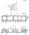
- the Fig. 18 shows a view of a Bankkühlmoduls invention 30.
- the Bankksselmodul 30 is formed by a base plate 31, on which one or more heat transfer elements are arranged.
- a capacitor region 33 is arranged, which is constructed in stacked disk construction of a plurality of disk elements 32.
- the spatial directions 47 and 49 are shown, which are at a right angle to each other.
- the spatial direction 47 indicates an orientation in which the Bankksselmodul 30 is preferably mounted in the installed position.
- the direction 47 is directed from bottom to top.
- the Fig. 19 shows a side view of the Schukühlmoduls 30, wherein the view of the viewer along the spatial direction 49 is directed.
- a condenser region 33, a collector 34, an internal heat exchanger 35 and an evaporator region 36 are arranged side by side on the base plate 31 of the heating cooling module 30.
- the individual regions 33, 34, 35 and 36 are each arranged at a distance from one another along the common base plate 31.
- the base plate 31 has a first fluid inlet 41, a first fluid outlet 42, a second fluid inlet 43, a second fluid outlet 44, a third fluid inlet 45 and a fourth fluid outlet 46.
- a coolant can be conducted through the condenser region 33 through the fluid connections 41, 42.
- a second coolant, in particular through the evaporator region 36, can be passed through the fluid connections 43, 44.
- the fluid connections 45, 46 serve to supply and discharge a refrigerant, which can flow through a plurality of the heat transfer elements 33, 34, 35 and 36 of the Schukühlmoduls 30.
- a fluid inlet can also function as a fluid outlet and vice versa.
- the fluid ports 41 to 46 are all arranged in the common base plate 31. Preferably, these are arranged on a common outer surface of the base plate 31. This makes the connection of the heating cooling module 30 to connection lines particularly easy.
- the refrigerant can flow through the condenser region 33 and flow from there into the collector 34. From the collector 34, the refrigerant can flow into the inner heat exchanger 35, where it is brought into particular in a heat transfer with the refrigerant, which has flowed through the inner heat exchanger 35 downstream evaporator region 36. From there, from the inner heat exchanger 35, the refrigerant can flow out of the base plate 31 of the Schukühlmoduls 30. In the flow path 39 of the refrigerant, an expansion valve 40 is arranged in the region between the inner heat exchanger 35 and the evaporator region 36. This expansion valve 40 is preferably part of the base plate 31st
- the base plate 31 has a plurality of flow channels, which in particular the fluid transfer between the individual heat transfer elements 33, 34, 35 and 36 accomplish.
- the individual heat exchanger elements 33 to 36 are connected via openings which face the base plate 31, fluidly connected to the respective flow channels of the base plate 31, so that a flow through the individual heat exchanger elements 33 to 36 can take place.
- the Fig. 20 shows a view from above against the spatial direction 47 on the Schukühlmodul 30.
- the heat transfer elements 33 to 36 spaced from each other on a common surface of the base plate 31 are arranged.
- the condenser region 33, the inner heat exchanger 35 and the evaporator region 36 are formed in stacked disk design by the stacking of several disc elements.
- the fluid ports 41 to 46 are arranged on a common outer surface of the base plate 31.
- the fluid connections 41 to 46 may in particular be formed by connecting flanges, to which connection lines can be connected in a simple manner.
- the connection lines can advantageously be connected via detachable connections.
- the flow through the individual heat exchanger elements 33 to 36 can be achieved by a variety of different structures of the individual elements 33 to 36.
- different flow channels and flow paths can be formed within the individual heat exchanger elements 33 to 36.
- the Fig. 21 shows a view of a Schukühlmoduls 30 in an orientation as the Fig. 19 equivalent.
- a condenser region 33, a collector 34, a subcooling region 48, an internal heat exchanger 35 and an evaporator region 36 are arranged side by side from the left side.
- the Fig. 21 becomes the capacitor region 33 as in the previous one Fig. 19 and flows through in the following figures, along the flow path 38 of a first coolant via the fluid ports 41, 42.
- the evaporator section 36 as in the preceding and following figures, along the flow path 37 flows through a second coolant through the fluid ports 43, 44.
- Fig. 19 In contrast to Fig. 19 has the flow path 38 from the condenser region 33 outgoing an additional loop, which is guided within the base plate 31 past the collector 34 to the subcooling 48. In this way, in the subcooling region 48, a further heat transfer between the coolant which has flowed through the condenser region 33 and the refrigerant which flows along the flow path 39 through the heat transfer elements 33, 34, 35, 36 and 48 and through the base plate 31 is possible ,
- the individual elements on the base plate 31 are also arranged spaced from each other, wherein in particular between the inner heat exchanger 35 and the evaporator region also an expansion valve 40 is arranged.
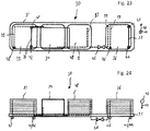
- the Fig. 22 shows a view corresponding to the viewing direction of Fig. 20 from above onto the heating cooling module 30.
- All heat exchanger elements 33, 48, 35 and 36 are made up of the collector 34 in a disk stack construction of individual disk elements.
- the refrigerant is transferred from the condenser region 33 into the adjacent collector 34, from where it is conducted through the base plate 31 into the subcooling region 48. There, as already mentioned, it causes a renewed heat transfer with the coolant of the condenser region 33. From the subcooling region 48, the refrigerant is passed on to the internal heat exchanger 35, where heat transfer is achieved with a proportion of the coolant which has already flowed through the evaporator region 36.
- the flow channels in the base plate 31 are formed such that a corresponding to the embodiment of Fig. 22 shown fluid guide is made possible.
- the expansion valve 40 is in the Fig. 22 as also preferred in the previous figures and following figures disposed within the base plate 31 or directly adjacent to the base plate 31.
- the Fig. 23 shows a view according to the viewing direction of Fig. 21 to a Schukühlmodul 30, to which a condenser region 33 next to a collector 34, a subcooling 48 and an evaporator section 36 is arranged.
- the condenser region 33 is flowed through by a first coolant along the flow path 38.
- the coolant is also passed through a loop, which is formed by flow channels in the base plate 31, to the subcooling region 48.
- Analogous to Fig. 21 the subcooling region 48 is also flowed through by this coolant.
- the refrigerant successively flows through the condenser region 33, the collector 34, the subcooling region 48 and the evaporator region 36. There, a heat exchange takes place between the refrigerant and the first or the second coolant analogously to the exemplary embodiment of FIG Fig. 21 instead of.
- the condenser region 33, the subcooling region 48 and the evaporator region 36 are likewise each formed by a stacking together of a plurality of disk elements, while the collector 34 is preferably formed from a single element. In alternative embodiments, however, the collector 34 may be formed in a construction of stacked disc elements.
- the Fig. 24 which shows a view opposite to the spatial direction 47 from above onto the heating cooling module 30, again shows the arrangement of the various flow channels within the base plate 31.
- the Fig. 25 shows an alternative orientation of a Bankkühlmoduls 30, which shows a capacitor region 33 on a base plate 31.
- the spatial direction 47 which is directed from bottom to top in an imaginary installation end position, is now facing away from the base plate 31 to the base plate 31 end portion of the Condenser region 33 directed.
- the second spatial direction 49 is parallel to the base plate 31 at a right angle to the spatial direction 47.
- the Fig. 26 shows an alternative orientation of a Schukühlmoduls 30.
- the spatial direction 47 which is directed along an installation position from bottom to top, now runs parallel to the long side of the base plate 31.
- the condenser region 33 is overhead, including the collector 34, including the inner heat exchanger 35 and below the evaporator portion 36 disposed on a common outer surface of the base plate 31.
- the condenser region 33 is also traversed along the flow path 38 by a first coolant in a direction which is parallel to the spatial direction 47.
- the evaporator region 36 is flowed through by a coolant along the flow path 47 between the fluid connections 43 and 44 in a direction parallel to the spatial direction 47.
- the refrigerant is, as in the previous figures, led from the condenser region 33 via the collector 34, the inner heat exchanger 35 and the evaporator section 36 through an expansion valve 40, wherein in the different areas, a heat transfer with the refrigerant itself or with the coolant.
- the Fig. 27 shows a view of the Schukühlmoduls 30 of Fig. 26 , where the view of the viewer along the spatial direction 49 of the Fig. 26 is directed.
- the base plate 31 has the heat transfer elements 33 to 36 to the left and the fluid connections 41 to 46 to the right. Furthermore, the flow channels for the fluidic connection of the individual heat transfer elements 33 to 36 are arranged inside the base plate 31.
- the individual heat exchanger elements 33 to 36 in particular different Can have size expansions.
- the individual areas can be dimensioned in particular depending on the required cooling or heating capacity.
- the individual heat exchanger elements 33 to 36 and 48 can be attached to the base plate 31 in a thermally insulated manner, in particular. This applies to all embodiments of the previously shown Fig. 1 to 27 , In this way, an undesired heat transfer between the individual heat exchanger elements 33, 34, 35, 36 and 48 or within the heat transfer elements 33, 34, 35, 36 and 48 flowing coolant and the refrigerant can be reduced.
- the final installation direction of the individual Thompsonksselmodule 30 may differ from each other, as well as the flow direction of the individual flow channels and flow paths 37, 38 and 39. In this way, different flow scenarios within the Schuksselmodule 30 can be achieved.
- each individual heat transfer element 33 to 36 and 48 can be generated due to the arrangement of the individual disc elements or the openings between the disc elements or the structuring of the collector 34.
- areas can be generated in which refrigerant and coolant or refrigerant and refrigerant flow in cocurrent or in countercurrent to one another.
- the individual heat exchanger elements 33 to 36 and 48 no limits by the representation of Fig. 18 to 27 set.
- the individual heat exchanger elements 33 to 36 and 48 can be constructed as, in particular, corresponding to the solutions known from the prior art for individual condenser regions, evaporator regions, collectors, internal heat exchangers or subcooling regions.
- the Fig. 18 to 27 have no restrictive effect in this regard.
- FIG. 18 to 27 can the individual flow concepts, which in schematic views in the Fig. 1 to 17 are also shown on an analogous to the embodiments of the invention Fig. 18 to 27 executed Schukühlmodul 30 are transferred.
- the Fig. 1 to 17 Here, in particular, a non-exhaustive list of possible connections of the individual heat exchanger elements with each other. These can be without limitation to the designs of Fig. 18 to 27 be transmitted.
Landscapes
- Engineering & Computer Science (AREA)
- Physics & Mathematics (AREA)
- Thermal Sciences (AREA)
- Mechanical Engineering (AREA)
- General Engineering & Computer Science (AREA)
- Chemical & Material Sciences (AREA)
- Chemical Kinetics & Catalysis (AREA)
- Manufacturing & Machinery (AREA)
- Electrochemistry (AREA)
- General Chemical & Material Sciences (AREA)
- Power Engineering (AREA)
- Analytical Chemistry (AREA)
- Heat-Exchange Devices With Radiators And Conduit Assemblies (AREA)
- Cooling Or The Like Of Electrical Apparatus (AREA)
- Air-Conditioning For Vehicles (AREA)
Claims (14)
- Module de chauffage et de refroidissement (30) servant à tempérer au moins deux circuits de liquide de refroidissement, ledit module de chauffage et de refroidissement comprenant une zone d'évaporateur (36) et une zone de condenseur (33), où la zone d'évaporateur (36) présente une première voie d'écoulement (37) qui peut être traversée par un premier liquide de refroidissement, et la zone de condenseur (33) présente une deuxième voie d'écoulement (38) qui peut être traversée par un second liquide de refroidissement, et où le module de chauffage et de refroidissement (30) présente une troisième voie d'écoulement (39) qui peut être traversée par un fluide frigorigène, où la zone d'évaporateur (36) et la zone de condenseur (33) sont disposées sur une plaque de base commune (31), caractérisé en ce que la plaque de base (31) présente les arrivées de fluide (41, 42, 43, 44, 45, 46) et les évacuations de fluide (41, 42, 43, 44, 45, 46) pour le premier liquide de refroidissement, pour le second liquide de refroidissement et pour le fluide frigorigène, et la plaque de base (31) présente des conduits d'écoulement qui peuvent être traversés à chaque fois par l'un des liquides de refroidissement ou par le fluide frigorigène, où la zone d'évaporateur (36) et la zone de condenseur (33) sont en communication fluidique, par les conduits d'écoulement, avec les arrivées de fluide respectives (41, 42, 43, 44, 45, 46) et avec les évacuations de fluide respectives (41, 42, 43, 44, 45, 46) de la plaque de base (31).
- Module de chauffage et de refroidissement (30) selon la revendication 1, caractérisé en ce qu'un détendeur thermostatique (40) est disposé sur ou dans la plaque de base (31), lequel détendeur peut être traversé par le fluide frigorigène.
- Module de chauffage et de refroidissement (30) selon l'une des revendications précédentes, caractérisé en ce qu'un collecteur (34) est disposé sur ou dans la plaque de base (31), lequel collecteur sert à l'accumulation et / ou au stockage et / ou à la filtration et / ou à la disseccation du fluide frigorigène.
- Module de chauffage et de refroidissement (30) selon l'une quelconque des revendications précédentes, caractérisé en ce qu'un échangeur de chaleur intérieur (35) et / ou une zone de surrefroidissement (48) est disposé (e) sur la plaque de base (31), où l'échangeur de chaleur intérieur (35) et / ou la zone de surrefroidissement (48) est également en communication fluidique avec des conduits d'écoulement de la plaque de base (31) et peut être traversé(e) par un fluide.
- Module de chauffage et de refroidissement (30) selon l'une quelconque des revendications précédentes, caractérisé en ce que la zone d'évaporateur (36) et / ou la zone de condenseur (33) et / ou l'échangeur de chaleur intérieur (35) et / ou la zone de surrefroidissement (48) et / ou le collecteur (34) est configuré (e) en étant du type de construction à plaques empilées de plusieurs éléments à plaques (32) empilés les uns sur les autres.
- Module de chauffage et de refroidissement (30) selon l'une quelconque des revendications précédentes, caractérisé en ce que les éléments (33, 34, 35, 36, 48) de l'échangeur de chaleur se trouvant sur la plaque de base (31) sont disposés sur une surface extérieure de la plaque de base (31), en étant contigus les uns aux autres dans une direction transversale par rapport à la direction d'empilement de l'une des piles de plaques.
- Module de chauffage et de refroidissement (30) selon l'une quelconque des revendications précédentes, caractérisé en ce que la zone de condenseur (33) et / ou la zone d'évaporateur (36) et / ou le collecteur (34) et / ou l'échangeur de chaleur intérieur (35) et / ou la zone de surrefroidissement (48) sont formé(e)s par des éléments à plaques communs, où les différents éléments (33, 34, 35, 36, 48) de l'échangeur de chaleur sont séparés fluidiquement les uns des autres, par des éléments de séparation placés dans les éléments à plaques respectifs.
- Module de chauffage et de refroidissement (30) selon l'une quelconque des revendications précédentes, caractérisé en ce que la plaque de base (31) présente des conduits d'écoulement par lesquels des éléments (33, 34, 35, 36, 48) de l'échangeur de chaleur, qui sont disposés en n'étant pas directement contigus les uns aux autres, peuvent être reliés fluidiquement les uns aux autres.
- Module de chauffage et de refroidissement (30) selon l'une quelconque des revendications précédentes, caractérisé en ce que la plaque de base (31) est configurée en plusieurs parties, où les conduits d'écoulement sont disposés à l'intérieur de la plaque de base (31) et sont recouverts, vers l'extérieur, par un élément de recouvrement ou par plusieurs éléments de recouvrement.
- Module de chauffage et de refroidissement (30) selon l'une quelconque des revendications précédentes, caractérisé en ce que les arrivées de fluide (41, 42, 43, 44, 45, 46) et les évacuations de fluide (41, 42, 43, 44, 45, 46) sont disposées sur une surface extérieure commune de la plaque de base (31).
- Module de chauffage et de refroidissement (30) selon l'une quelconque des revendications précédentes, caractérisé en ce que la surface extérieure de la plaque de base (31), qui présente les arrivées de fluide (41, 42, 43, 44, 45, 46) et les évacuations de fluide (41, 42, 43, 44, 45, 46), est placée en faisant face à la surface extérieure sur laquelle sont disposés les éléments (33, 34, 35, 36, 48) de l'échangeur de chaleur.
- Module de chauffage et de refroidissement (30) selon l'une quelconque des revendications précédentes, caractérisé en ce que les différents éléments (33, 34, 35, 36, 48) de l'échangeur de chaleur sont isolés thermiquement les uns des autres.
- Module de chauffage et de refroidissement (30) selon l'une quelconque des revendications précédentes, caractérisé en ce que les différents éléments (33, 34, 35, 36, 48) de l'échangeur de chaleur présentent différentes dimensions extérieures et / ou différents volumes intérieurs.
- Module de chauffage et de refroidissement (30) selon l'une quelconque des revendications précédentes, caractérisé en ce que la plaque de base (31) présente des éléments de positionnement qui forment une zone de logement pour au moins l'un des éléments (33, 34, 35, 36, 48) de l'échangeur de chaleur.
Applications Claiming Priority (2)
| Application Number | Priority Date | Filing Date | Title |
|---|---|---|---|
| DE102014204935.0A DE102014204935A1 (de) | 2014-03-17 | 2014-03-17 | Heizkühlmodul |
| PCT/EP2015/055178 WO2015140040A1 (fr) | 2014-03-17 | 2015-03-12 | Module de chauffage et de refroidissement |
Publications (2)
| Publication Number | Publication Date |
|---|---|
| EP3119623A1 EP3119623A1 (fr) | 2017-01-25 |
| EP3119623B1 true EP3119623B1 (fr) | 2019-11-27 |
Family
ID=52682715
Family Applications (1)
| Application Number | Title | Priority Date | Filing Date |
|---|---|---|---|
| EP15709918.5A Active EP3119623B1 (fr) | 2014-03-17 | 2015-03-12 | Module de chauffage et de refroidissement |
Country Status (5)
| Country | Link |
|---|---|
| US (1) | US10717338B2 (fr) |
| EP (1) | EP3119623B1 (fr) |
| CN (1) | CN106103153B (fr) |
| DE (1) | DE102014204935A1 (fr) |
| WO (1) | WO2015140040A1 (fr) |
Families Citing this family (15)
| Publication number | Priority date | Publication date | Assignee | Title |
|---|---|---|---|---|
| DE102015203141A1 (de) * | 2015-02-20 | 2016-08-25 | Mahle International Gmbh | Wärmeübertrager |
| DE102016007089A1 (de) * | 2016-06-10 | 2017-06-29 | Modine Manufacturing Company | Flanschplatte mit Unterkühlfunktion |
| JP6576320B2 (ja) * | 2016-10-14 | 2019-09-18 | 本田技研工業株式会社 | 空調ユニット |
| DE102017210185A1 (de) * | 2017-06-19 | 2018-12-20 | Robert Bosch Gmbh | Kühlsystem mit einer Mehrzahl an zu kühlenden Elementen |
| KR102621904B1 (ko) * | 2018-07-24 | 2024-01-05 | 현대자동차주식회사 | 수냉식 배터리 냉각 시스템 및 이를 이용한 냉각 방법 |
| EP3705324A1 (fr) * | 2019-03-04 | 2020-09-09 | Knorr-Bremse España S.A. | Système et procédé pour climatiseur de véhicule |
| WO2021048095A1 (fr) * | 2019-09-09 | 2021-03-18 | Brose Fahrzeugteile SE & Co. Kommanditgesellschaft, Würzburg | Module compact de régulation de la température d'un véhicule motorisé |
| DE112020004318T5 (de) * | 2019-09-13 | 2022-05-25 | Denso Corporation | Anschlussmodul |
| WO2022266945A1 (fr) * | 2021-06-24 | 2022-12-29 | 浙江吉利控股集团有限公司 | Appareil d'intégration de conduites de refroidissement à canaux multiples, module d'intégration de gestion thermique et véhicule électrique |
| KR20230041517A (ko) * | 2021-09-17 | 2023-03-24 | 현대자동차주식회사 | 유체흐름용 플레이트구조 |
| DE102022201204A1 (de) | 2022-02-04 | 2023-08-10 | Mahle International Gmbh | Wärmeübertragermodul |
| FR3133434A1 (fr) * | 2022-03-08 | 2023-09-15 | Valeo Systemes Thermiques | Plaque commune d’un module thermique d’un circuit de fluide réfrigérant |
| FR3133435A1 (fr) * | 2022-03-08 | 2023-09-15 | Valeo Systemes Thermiques | Plaque commune d’un module thermique d’un circuit de fluide réfrigérant |
| FR3133432A1 (fr) * | 2022-03-08 | 2023-09-15 | Valeo Systemes Thermiques | Plaque commune d’un module thermique d’un circuit de fluide réfrigérant |
| FR3135422A1 (fr) * | 2022-05-10 | 2023-11-17 | Valeo Systemes Thermiques | Système de conditionnement thermique comprenant un module de gestion des fluides pour un véhicule notamment automobile |
Family Cites Families (33)
| Publication number | Priority date | Publication date | Assignee | Title |
|---|---|---|---|---|
| US4129014A (en) * | 1977-07-22 | 1978-12-12 | Chubb Talbot A | Refrigeration storage and cooling tank |
| US6148635A (en) * | 1998-10-19 | 2000-11-21 | The Board Of Trustees Of The University Of Illinois | Active compressor vapor compression cycle integrated heat transfer device |
| US6318115B1 (en) * | 2000-05-08 | 2001-11-20 | KENMORE THERMOKäLTE GMBH | Refrigeration circuit and apparatus |
| WO2003054465A1 (fr) | 2001-12-21 | 2003-07-03 | Behr Gmbh & Co. | Dispositif d'echange de chaleur |
| US20040055322A1 (en) * | 2002-09-19 | 2004-03-25 | Sun Microsystems, Inc. | Field replaceable packard refrigeration module with vapor chamber heat sink for cooling electronic components |
| US20040079100A1 (en) * | 2002-10-25 | 2004-04-29 | Sun Microsystems, Inc. | Field replaceable packaged refrigeration module with capillary pumped loop for cooling electronic components |
| FR2846734B1 (fr) * | 2002-10-31 | 2017-09-01 | Valeo Thermique Moteur Sa | Module d'echangeur de chaleur a plaques comportant une section d'echange de chaleur refroidie a l'air atmospherique, notamment pour un vehicule automobile |
| GB2451404B (en) * | 2006-05-12 | 2010-11-17 | Allen Vanguard Technologies Inc | Temperature controlled container |
| US7753105B2 (en) * | 2006-05-16 | 2010-07-13 | Delphi Technologies, Inc. | Liquid cooled condenser having an integrated heat exchanger |
| JP4657226B2 (ja) * | 2007-02-01 | 2011-03-23 | トヨタ自動車株式会社 | 蓄熱装置 |
| JP4505510B2 (ja) | 2007-02-20 | 2010-07-21 | カルソニックカンセイ株式会社 | 車両用空調システム |
| EP2321605B1 (fr) * | 2008-07-31 | 2018-09-12 | Georgia Tech Research Corporation | Système d'échelle microscopique de transfert de chaleur ou de transfert de chaleur et de masse |
| US20110232859A1 (en) * | 2008-08-28 | 2011-09-29 | Ac Research Labs | Air Conditioner Cooling Device |
| SE534348C2 (sv) * | 2008-10-07 | 2011-07-19 | Scania Cv Abp | System och anordning innefattande en sammanbyggd kondensor och förångare |
| DE102010026507A1 (de) * | 2010-07-07 | 2012-01-12 | Behr Gmbh & Co. Kg | Kältemittelkondensatormodul |
| DE102010048015B4 (de) | 2010-10-09 | 2015-11-05 | Modine Manufacturing Co. | Anlage mit einem Wärmeübertrager |
| DE102011008653A1 (de) * | 2011-01-14 | 2012-07-19 | Behr Gmbh & Co. Kg | Wärmeübertrager |
| US9109840B2 (en) * | 2011-02-17 | 2015-08-18 | Delphi Technologies, Inc. | Unitary heat pump air conditioner having a heat exchanger with an integral accumulator |
| US8899062B2 (en) * | 2011-02-17 | 2014-12-02 | Delphi Technologies, Inc. | Plate-type heat pump air conditioner heat exchanger for a unitary heat pump air conditioner |
| US9239193B2 (en) * | 2011-02-17 | 2016-01-19 | Delphi Technologies, Inc. | Unitary heat pump air conditioner having a heat exchanger with an integral receiver and sub-cooler |
| EP2694899B1 (fr) * | 2011-04-01 | 2017-08-02 | Ingersoll-Rand Company | Echangeur de chaleur pour un dessiccateur d'air réfrigéré |
| DE102011078136A1 (de) * | 2011-06-27 | 2012-12-27 | Behr Gmbh & Co. Kg | Kältemittelkondensatormodul |
| DE102012002768A1 (de) * | 2012-02-11 | 2012-09-20 | Daimler Ag | Wärmetauschermodul und Verfahren zum Betrieb eines Wärmetauschermoduls |
| US9175883B2 (en) * | 2013-06-24 | 2015-11-03 | Ford Global Technologies, Llc | Internal heat exchanger with integrated receiver/dryer and thermal expansion valve |
| BR102013017090A2 (pt) * | 2013-07-02 | 2015-06-30 | Mahle Metal Leve Sa | Trocador de calor para alimentação de combustível em motores de combustão interna |
| DE102014204936A1 (de) * | 2014-03-17 | 2015-10-01 | Mahle International Gmbh | Heizkühlmodul |
| DE102014004322B4 (de) * | 2014-03-25 | 2020-08-27 | Modine Manufacturing Company | Wärmerückgewinnungssystem und Plattenwärmetauscher |
| JP6222042B2 (ja) * | 2014-05-23 | 2017-11-01 | 株式会社デンソー | 積層型熱交換器 |
| JP6242769B2 (ja) * | 2014-08-21 | 2017-12-06 | 株式会社神戸製鋼所 | 圧縮装置 |
| WO2016032482A1 (fr) * | 2014-08-28 | 2016-03-03 | Aavid Thermalloy, Llc | Thermosiphon à composants intégrés |
| DE102015215410A1 (de) * | 2015-08-12 | 2017-02-16 | Mahle International Gmbh | Stapelscheiben-Wärmeübertrager, insbesondere Ladeluftkühler |
| JP6321067B2 (ja) * | 2016-03-31 | 2018-05-09 | 住友精密工業株式会社 | 拡散接合型熱交換器 |
| CN108507218A (zh) * | 2018-05-10 | 2018-09-07 | 谈达伟 | 一种可变体积的新型制冷系统 |
-
2014
- 2014-03-17 DE DE102014204935.0A patent/DE102014204935A1/de not_active Withdrawn
-
2015
- 2015-03-12 CN CN201580014145.XA patent/CN106103153B/zh active Active
- 2015-03-12 WO PCT/EP2015/055178 patent/WO2015140040A1/fr active Application Filing
- 2015-03-12 EP EP15709918.5A patent/EP3119623B1/fr active Active
-
2016
- 2016-09-13 US US15/263,410 patent/US10717338B2/en active Active
Non-Patent Citations (1)
| Title |
|---|
| None * |
Also Published As
| Publication number | Publication date |
|---|---|
| CN106103153A (zh) | 2016-11-09 |
| WO2015140040A1 (fr) | 2015-09-24 |
| CN106103153B (zh) | 2018-11-16 |
| DE102014204935A1 (de) | 2015-10-01 |
| EP3119623A1 (fr) | 2017-01-25 |
| US20160375740A1 (en) | 2016-12-29 |
| US10717338B2 (en) | 2020-07-21 |
Similar Documents
| Publication | Publication Date | Title |
|---|---|---|
| EP3119623B1 (fr) | Module de chauffage et de refroidissement | |
| EP3119622B1 (fr) | Module de chauffage et de refroidissement | |
| EP2904335B1 (fr) | Condenseur | |
| WO2004113815A1 (fr) | Dispositif d'echange thermique polyetage et procede de fabrication d'un tel dispositif | |
| DE10314782A1 (de) | Wärmetauscher für den Wärmeaustausch zwischen einem inneren und einem äußeren Fluid und Verfahren zur Herstellung desselben | |
| DE112015000465B4 (de) | Klimaanlagensystem für ein Fahrzeug | |
| DE102008063262A1 (de) | Wärmetauscher | |
| DE102011057190A1 (de) | Wärmetauscher für ein Fahrzeug | |
| DE102006057585A1 (de) | Wärmetauscher und Kältemittelverdampfer | |
| EP2798297B1 (fr) | Méthode de fabrication d'au moins deux échangeurs de chaleur différents | |
| DE202021102042U1 (de) | Zwei Wärmetauscher mit integriertem Umleitventil | |
| DE102013220039A1 (de) | Wärmeübertrager | |
| WO2014184323A1 (fr) | Condenseur | |
| WO2005100895A1 (fr) | Echangeur de chaleur pour vehicules automobiles | |
| EP2926073B1 (fr) | Échangeur thermique | |
| EP2636958A2 (fr) | Répartiteur de circuit de chauffage avec vase de découplage hydraulique intégré | |
| DE202014101213U1 (de) | Heizkühlmodul | |
| WO2014095594A1 (fr) | Échangeur de chaleur | |
| EP2049859B1 (fr) | Climatisation pour véhicule à moteur | |
| DE112017001907T5 (de) | Energiewiedergewinnungseinheit für den Fahrzeuggebrauch | |
| DE102006002018A1 (de) | Plattenwärmeübertrager nach dem Gegenstromprinzip | |
| DE102013214695A1 (de) | Kondensator | |
| DE102012017404A1 (de) | Interner Wärmetauscher für eine Kraftfahrzeug-Klimaanlage | |
| EP1553273B1 (fr) | Système de refroidissement | |
| DE60201554T2 (de) | Verdampfer mit hoher Kälteleistung für Kraftfahrzeugklimaanlage |
Legal Events
| Date | Code | Title | Description |
|---|---|---|---|
| STAA | Information on the status of an ep patent application or granted ep patent |
Free format text: STATUS: THE INTERNATIONAL PUBLICATION HAS BEEN MADE |
|
| PUAI | Public reference made under article 153(3) epc to a published international application that has entered the european phase |
Free format text: ORIGINAL CODE: 0009012 |
|
| STAA | Information on the status of an ep patent application or granted ep patent |
Free format text: STATUS: REQUEST FOR EXAMINATION WAS MADE |
|
| 17P | Request for examination filed |
Effective date: 20161017 |
|
| AK | Designated contracting states |
Kind code of ref document: A1 Designated state(s): AL AT BE BG CH CY CZ DE DK EE ES FI FR GB GR HR HU IE IS IT LI LT LU LV MC MK MT NL NO PL PT RO RS SE SI SK SM TR |
|
| AX | Request for extension of the european patent |
Extension state: BA ME |
|
| DAV | Request for validation of the european patent (deleted) | ||
| DAX | Request for extension of the european patent (deleted) | ||
| GRAP | Despatch of communication of intention to grant a patent |
Free format text: ORIGINAL CODE: EPIDOSNIGR1 |
|
| RIC1 | Information provided on ipc code assigned before grant |
Ipc: B60H 1/32 20060101ALI20190506BHEP Ipc: F25B 25/00 20060101ALI20190506BHEP Ipc: F28F 3/08 20060101ALI20190506BHEP Ipc: B60H 1/00 20060101AFI20190506BHEP Ipc: H01M 10/625 20140101ALI20190506BHEP Ipc: H01M 10/6556 20140101ALI20190506BHEP |
|
| STAA | Information on the status of an ep patent application or granted ep patent |
Free format text: STATUS: GRANT OF PATENT IS INTENDED |
|
| INTG | Intention to grant announced |
Effective date: 20190613 |
|
| GRAS | Grant fee paid |
Free format text: ORIGINAL CODE: EPIDOSNIGR3 |
|
| GRAJ | Information related to disapproval of communication of intention to grant by the applicant or resumption of examination proceedings by the epo deleted |
Free format text: ORIGINAL CODE: EPIDOSDIGR1 |
|
| GRAL | Information related to payment of fee for publishing/printing deleted |
Free format text: ORIGINAL CODE: EPIDOSDIGR3 |
|
| STAA | Information on the status of an ep patent application or granted ep patent |
Free format text: STATUS: REQUEST FOR EXAMINATION WAS MADE |
|
| GRAR | Information related to intention to grant a patent recorded |
Free format text: ORIGINAL CODE: EPIDOSNIGR71 |
|
| STAA | Information on the status of an ep patent application or granted ep patent |
Free format text: STATUS: GRANT OF PATENT IS INTENDED |
|
| GRAA | (expected) grant |
Free format text: ORIGINAL CODE: 0009210 |
|
| STAA | Information on the status of an ep patent application or granted ep patent |
Free format text: STATUS: THE PATENT HAS BEEN GRANTED |
|
| RIN1 | Information on inventor provided before grant (corrected) |
Inventor name: DUERR, GOTTFRIED Inventor name: HOFMANN, HERBERT Inventor name: HAUG, JOACHIM MICHAEL |
|
| INTC | Intention to grant announced (deleted) | ||
| INTG | Intention to grant announced |
Effective date: 20191017 |
|
| AK | Designated contracting states |
Kind code of ref document: B1 Designated state(s): AL AT BE BG CH CY CZ DE DK EE ES FI FR GB GR HR HU IE IS IT LI LT LU LV MC MK MT NL NO PL PT RO RS SE SI SK SM TR |
|
| REG | Reference to a national code |
Ref country code: GB Ref legal event code: FG4D Free format text: NOT ENGLISH |
|
| REG | Reference to a national code |
Ref country code: CH Ref legal event code: EP |
|
| REG | Reference to a national code |
Ref country code: AT Ref legal event code: REF Ref document number: 1206250 Country of ref document: AT Kind code of ref document: T Effective date: 20191215 |
|
| REG | Reference to a national code |
Ref country code: DE Ref legal event code: R096 Ref document number: 502015011055 Country of ref document: DE |
|
| REG | Reference to a national code |
Ref country code: IE Ref legal event code: FG4D Free format text: LANGUAGE OF EP DOCUMENT: GERMAN |
|
| REG | Reference to a national code |
Ref country code: NL Ref legal event code: MP Effective date: 20191127 |
|
| REG | Reference to a national code |
Ref country code: LT Ref legal event code: MG4D |
|
| PG25 | Lapsed in a contracting state [announced via postgrant information from national office to epo] |
Ref country code: LV Free format text: LAPSE BECAUSE OF FAILURE TO SUBMIT A TRANSLATION OF THE DESCRIPTION OR TO PAY THE FEE WITHIN THE PRESCRIBED TIME-LIMIT Effective date: 20191127 Ref country code: SE Free format text: LAPSE BECAUSE OF FAILURE TO SUBMIT A TRANSLATION OF THE DESCRIPTION OR TO PAY THE FEE WITHIN THE PRESCRIBED TIME-LIMIT Effective date: 20191127 Ref country code: FI Free format text: LAPSE BECAUSE OF FAILURE TO SUBMIT A TRANSLATION OF THE DESCRIPTION OR TO PAY THE FEE WITHIN THE PRESCRIBED TIME-LIMIT Effective date: 20191127 Ref country code: BG Free format text: LAPSE BECAUSE OF FAILURE TO SUBMIT A TRANSLATION OF THE DESCRIPTION OR TO PAY THE FEE WITHIN THE PRESCRIBED TIME-LIMIT Effective date: 20200227 Ref country code: NO Free format text: LAPSE BECAUSE OF FAILURE TO SUBMIT A TRANSLATION OF THE DESCRIPTION OR TO PAY THE FEE WITHIN THE PRESCRIBED TIME-LIMIT Effective date: 20200227 Ref country code: GR Free format text: LAPSE BECAUSE OF FAILURE TO SUBMIT A TRANSLATION OF THE DESCRIPTION OR TO PAY THE FEE WITHIN THE PRESCRIBED TIME-LIMIT Effective date: 20200228 Ref country code: NL Free format text: LAPSE BECAUSE OF FAILURE TO SUBMIT A TRANSLATION OF THE DESCRIPTION OR TO PAY THE FEE WITHIN THE PRESCRIBED TIME-LIMIT Effective date: 20191127 Ref country code: LT Free format text: LAPSE BECAUSE OF FAILURE TO SUBMIT A TRANSLATION OF THE DESCRIPTION OR TO PAY THE FEE WITHIN THE PRESCRIBED TIME-LIMIT Effective date: 20191127 |
|
| PG25 | Lapsed in a contracting state [announced via postgrant information from national office to epo] |
Ref country code: HR Free format text: LAPSE BECAUSE OF FAILURE TO SUBMIT A TRANSLATION OF THE DESCRIPTION OR TO PAY THE FEE WITHIN THE PRESCRIBED TIME-LIMIT Effective date: 20191127 Ref country code: IS Free format text: LAPSE BECAUSE OF FAILURE TO SUBMIT A TRANSLATION OF THE DESCRIPTION OR TO PAY THE FEE WITHIN THE PRESCRIBED TIME-LIMIT Effective date: 20200327 Ref country code: RS Free format text: LAPSE BECAUSE OF FAILURE TO SUBMIT A TRANSLATION OF THE DESCRIPTION OR TO PAY THE FEE WITHIN THE PRESCRIBED TIME-LIMIT Effective date: 20191127 |
|
| PG25 | Lapsed in a contracting state [announced via postgrant information from national office to epo] |
Ref country code: AL Free format text: LAPSE BECAUSE OF FAILURE TO SUBMIT A TRANSLATION OF THE DESCRIPTION OR TO PAY THE FEE WITHIN THE PRESCRIBED TIME-LIMIT Effective date: 20191127 |
|
| PG25 | Lapsed in a contracting state [announced via postgrant information from national office to epo] |
Ref country code: PT Free format text: LAPSE BECAUSE OF FAILURE TO SUBMIT A TRANSLATION OF THE DESCRIPTION OR TO PAY THE FEE WITHIN THE PRESCRIBED TIME-LIMIT Effective date: 20200419 Ref country code: EE Free format text: LAPSE BECAUSE OF FAILURE TO SUBMIT A TRANSLATION OF THE DESCRIPTION OR TO PAY THE FEE WITHIN THE PRESCRIBED TIME-LIMIT Effective date: 20191127 Ref country code: RO Free format text: LAPSE BECAUSE OF FAILURE TO SUBMIT A TRANSLATION OF THE DESCRIPTION OR TO PAY THE FEE WITHIN THE PRESCRIBED TIME-LIMIT Effective date: 20191127 Ref country code: CZ Free format text: LAPSE BECAUSE OF FAILURE TO SUBMIT A TRANSLATION OF THE DESCRIPTION OR TO PAY THE FEE WITHIN THE PRESCRIBED TIME-LIMIT Effective date: 20191127 Ref country code: ES Free format text: LAPSE BECAUSE OF FAILURE TO SUBMIT A TRANSLATION OF THE DESCRIPTION OR TO PAY THE FEE WITHIN THE PRESCRIBED TIME-LIMIT Effective date: 20191127 Ref country code: DK Free format text: LAPSE BECAUSE OF FAILURE TO SUBMIT A TRANSLATION OF THE DESCRIPTION OR TO PAY THE FEE WITHIN THE PRESCRIBED TIME-LIMIT Effective date: 20191127 |
|
| REG | Reference to a national code |
Ref country code: DE Ref legal event code: R097 Ref document number: 502015011055 Country of ref document: DE |
|
| PG25 | Lapsed in a contracting state [announced via postgrant information from national office to epo] |
Ref country code: SM Free format text: LAPSE BECAUSE OF FAILURE TO SUBMIT A TRANSLATION OF THE DESCRIPTION OR TO PAY THE FEE WITHIN THE PRESCRIBED TIME-LIMIT Effective date: 20191127 Ref country code: SK Free format text: LAPSE BECAUSE OF FAILURE TO SUBMIT A TRANSLATION OF THE DESCRIPTION OR TO PAY THE FEE WITHIN THE PRESCRIBED TIME-LIMIT Effective date: 20191127 |
|
| PLBE | No opposition filed within time limit |
Free format text: ORIGINAL CODE: 0009261 |
|
| STAA | Information on the status of an ep patent application or granted ep patent |
Free format text: STATUS: NO OPPOSITION FILED WITHIN TIME LIMIT |
|
| PG25 | Lapsed in a contracting state [announced via postgrant information from national office to epo] |
Ref country code: MC Free format text: LAPSE BECAUSE OF FAILURE TO SUBMIT A TRANSLATION OF THE DESCRIPTION OR TO PAY THE FEE WITHIN THE PRESCRIBED TIME-LIMIT Effective date: 20191127 |
|
| REG | Reference to a national code |
Ref country code: CH Ref legal event code: PL |
|
| 26N | No opposition filed |
Effective date: 20200828 |
|
| PG25 | Lapsed in a contracting state [announced via postgrant information from national office to epo] |
Ref country code: SI Free format text: LAPSE BECAUSE OF FAILURE TO SUBMIT A TRANSLATION OF THE DESCRIPTION OR TO PAY THE FEE WITHIN THE PRESCRIBED TIME-LIMIT Effective date: 20191127 Ref country code: PL Free format text: LAPSE BECAUSE OF FAILURE TO SUBMIT A TRANSLATION OF THE DESCRIPTION OR TO PAY THE FEE WITHIN THE PRESCRIBED TIME-LIMIT Effective date: 20191127 |
|
| REG | Reference to a national code |
Ref country code: BE Ref legal event code: MM Effective date: 20200331 |
|
| PG25 | Lapsed in a contracting state [announced via postgrant information from national office to epo] |
Ref country code: LU Free format text: LAPSE BECAUSE OF NON-PAYMENT OF DUE FEES Effective date: 20200312 |
|
| PG25 | Lapsed in a contracting state [announced via postgrant information from national office to epo] |
Ref country code: LI Free format text: LAPSE BECAUSE OF NON-PAYMENT OF DUE FEES Effective date: 20200331 Ref country code: CH Free format text: LAPSE BECAUSE OF NON-PAYMENT OF DUE FEES Effective date: 20200331 Ref country code: IT Free format text: LAPSE BECAUSE OF FAILURE TO SUBMIT A TRANSLATION OF THE DESCRIPTION OR TO PAY THE FEE WITHIN THE PRESCRIBED TIME-LIMIT Effective date: 20191127 Ref country code: FR Free format text: LAPSE BECAUSE OF NON-PAYMENT OF DUE FEES Effective date: 20200331 Ref country code: IE Free format text: LAPSE BECAUSE OF NON-PAYMENT OF DUE FEES Effective date: 20200312 |
|
| PG25 | Lapsed in a contracting state [announced via postgrant information from national office to epo] |
Ref country code: BE Free format text: LAPSE BECAUSE OF NON-PAYMENT OF DUE FEES Effective date: 20200331 |
|
| GBPC | Gb: european patent ceased through non-payment of renewal fee |
Effective date: 20200312 |
|
| PG25 | Lapsed in a contracting state [announced via postgrant information from national office to epo] |
Ref country code: GB Free format text: LAPSE BECAUSE OF NON-PAYMENT OF DUE FEES Effective date: 20200312 |
|
| REG | Reference to a national code |
Ref country code: AT Ref legal event code: MM01 Ref document number: 1206250 Country of ref document: AT Kind code of ref document: T Effective date: 20200312 |
|
| PG25 | Lapsed in a contracting state [announced via postgrant information from national office to epo] |
Ref country code: AT Free format text: LAPSE BECAUSE OF NON-PAYMENT OF DUE FEES Effective date: 20200312 |
|
| PG25 | Lapsed in a contracting state [announced via postgrant information from national office to epo] |
Ref country code: TR Free format text: LAPSE BECAUSE OF FAILURE TO SUBMIT A TRANSLATION OF THE DESCRIPTION OR TO PAY THE FEE WITHIN THE PRESCRIBED TIME-LIMIT Effective date: 20191127 Ref country code: MT Free format text: LAPSE BECAUSE OF FAILURE TO SUBMIT A TRANSLATION OF THE DESCRIPTION OR TO PAY THE FEE WITHIN THE PRESCRIBED TIME-LIMIT Effective date: 20191127 Ref country code: CY Free format text: LAPSE BECAUSE OF FAILURE TO SUBMIT A TRANSLATION OF THE DESCRIPTION OR TO PAY THE FEE WITHIN THE PRESCRIBED TIME-LIMIT Effective date: 20191127 |
|
| PG25 | Lapsed in a contracting state [announced via postgrant information from national office to epo] |
Ref country code: MK Free format text: LAPSE BECAUSE OF FAILURE TO SUBMIT A TRANSLATION OF THE DESCRIPTION OR TO PAY THE FEE WITHIN THE PRESCRIBED TIME-LIMIT Effective date: 20191127 |
|
| PGFP | Annual fee paid to national office [announced via postgrant information from national office to epo] |
Ref country code: DE Payment date: 20240320 Year of fee payment: 10 |