EP3119262B1 - Pumpenvorrichtung - Google Patents
Pumpenvorrichtung Download PDFInfo
- Publication number
- EP3119262B1 EP3119262B1 EP15709877.3A EP15709877A EP3119262B1 EP 3119262 B1 EP3119262 B1 EP 3119262B1 EP 15709877 A EP15709877 A EP 15709877A EP 3119262 B1 EP3119262 B1 EP 3119262B1
- Authority
- EP
- European Patent Office
- Prior art keywords
- pump
- optical fiber
- light source
- light
- tube
- Prior art date
- Legal status (The legal status is an assumption and is not a legal conclusion. Google has not performed a legal analysis and makes no representation as to the accuracy of the status listed.)
- Not-in-force
Links
- 239000013307 optical fiber Substances 0.000 claims description 60
- 239000007788 liquid Substances 0.000 claims description 13
- 239000012530 fluid Substances 0.000 claims description 12
- 230000008859 change Effects 0.000 claims description 3
- 230000007423 decrease Effects 0.000 claims description 3
- 238000006243 chemical reaction Methods 0.000 claims description 2
- 230000001419 dependent effect Effects 0.000 claims description 2
- 238000012544 monitoring process Methods 0.000 claims description 2
- 230000005855 radiation Effects 0.000 claims 2
- 230000007547 defect Effects 0.000 description 15
- 230000002262 irrigation Effects 0.000 description 7
- 238000003973 irrigation Methods 0.000 description 7
- 239000012535 impurity Substances 0.000 description 3
- 239000008280 blood Substances 0.000 description 2
- 210000004369 blood Anatomy 0.000 description 2
- 238000005253 cladding Methods 0.000 description 2
- 239000003086 colorant Substances 0.000 description 2
- 230000008878 coupling Effects 0.000 description 2
- 238000010168 coupling process Methods 0.000 description 2
- 238000005859 coupling reaction Methods 0.000 description 2
- OAICVXFJPJFONN-UHFFFAOYSA-N Phosphorus Chemical compound [P] OAICVXFJPJFONN-UHFFFAOYSA-N 0.000 description 1
- 238000004026 adhesive bonding Methods 0.000 description 1
- 230000008901 benefit Effects 0.000 description 1
- 238000011161 development Methods 0.000 description 1
- 230000018109 developmental process Effects 0.000 description 1
- 238000005516 engineering process Methods 0.000 description 1
- 238000000034 method Methods 0.000 description 1
- 238000002324 minimally invasive surgery Methods 0.000 description 1
- 230000008569 process Effects 0.000 description 1
- 238000005086 pumping Methods 0.000 description 1
- 230000007704 transition Effects 0.000 description 1
Images


Classifications
-
- A—HUMAN NECESSITIES
- A61—MEDICAL OR VETERINARY SCIENCE; HYGIENE
- A61B—DIAGNOSIS; SURGERY; IDENTIFICATION
- A61B1/00—Instruments for performing medical examinations of the interior of cavities or tubes of the body by visual or photographical inspection, e.g. endoscopes; Illuminating arrangements therefor
- A61B1/00002—Operational features of endoscopes
- A61B1/00043—Operational features of endoscopes provided with output arrangements
- A61B1/00055—Operational features of endoscopes provided with output arrangements for alerting the user
-
- A—HUMAN NECESSITIES
- A61—MEDICAL OR VETERINARY SCIENCE; HYGIENE
- A61B—DIAGNOSIS; SURGERY; IDENTIFICATION
- A61B1/00—Instruments for performing medical examinations of the interior of cavities or tubes of the body by visual or photographical inspection, e.g. endoscopes; Illuminating arrangements therefor
- A61B1/00002—Operational features of endoscopes
- A61B1/00043—Operational features of endoscopes provided with output arrangements
- A61B1/00045—Display arrangement
-
- A—HUMAN NECESSITIES
- A61—MEDICAL OR VETERINARY SCIENCE; HYGIENE
- A61B—DIAGNOSIS; SURGERY; IDENTIFICATION
- A61B1/00—Instruments for performing medical examinations of the interior of cavities or tubes of the body by visual or photographical inspection, e.g. endoscopes; Illuminating arrangements therefor
- A61B1/00163—Optical arrangements
- A61B1/00165—Optical arrangements with light-conductive means, e.g. fibre optics
-
- A—HUMAN NECESSITIES
- A61—MEDICAL OR VETERINARY SCIENCE; HYGIENE
- A61B—DIAGNOSIS; SURGERY; IDENTIFICATION
- A61B1/00—Instruments for performing medical examinations of the interior of cavities or tubes of the body by visual or photographical inspection, e.g. endoscopes; Illuminating arrangements therefor
- A61B1/012—Instruments for performing medical examinations of the interior of cavities or tubes of the body by visual or photographical inspection, e.g. endoscopes; Illuminating arrangements therefor characterised by internal passages or accessories therefor
- A61B1/015—Control of fluid supply or evacuation
-
- A—HUMAN NECESSITIES
- A61—MEDICAL OR VETERINARY SCIENCE; HYGIENE
- A61B—DIAGNOSIS; SURGERY; IDENTIFICATION
- A61B1/00—Instruments for performing medical examinations of the interior of cavities or tubes of the body by visual or photographical inspection, e.g. endoscopes; Illuminating arrangements therefor
- A61B1/06—Instruments for performing medical examinations of the interior of cavities or tubes of the body by visual or photographical inspection, e.g. endoscopes; Illuminating arrangements therefor with illuminating arrangements
- A61B1/07—Instruments for performing medical examinations of the interior of cavities or tubes of the body by visual or photographical inspection, e.g. endoscopes; Illuminating arrangements therefor with illuminating arrangements using light-conductive means, e.g. optical fibres
-
- A—HUMAN NECESSITIES
- A61—MEDICAL OR VETERINARY SCIENCE; HYGIENE
- A61B—DIAGNOSIS; SURGERY; IDENTIFICATION
- A61B1/00—Instruments for performing medical examinations of the interior of cavities or tubes of the body by visual or photographical inspection, e.g. endoscopes; Illuminating arrangements therefor
- A61B1/12—Instruments for performing medical examinations of the interior of cavities or tubes of the body by visual or photographical inspection, e.g. endoscopes; Illuminating arrangements therefor with cooling or rinsing arrangements
Definitions
- the invention relates to pump devices for use in operating theaters and arrangements from corresponding pump devices and endoscopes.
- pumps are often found as part of medical devices or as separate units connected to medical devices. Examples include suction pumps or heart-lung machines. Pumps are also used to deliver irrigation fluids to an operating area, with which resected tissue and blood can be flushed out of the operating area.
- Corresponding pumps according to the state of the art used in operating theaters provide information about their operating state, for example the basic switch-on state of the pump or the flow rate, via a display arranged on their housing.
- the housing of the pump or the display arranged on it is usually not in the field of vision of the surgeon, so that he has to turn towards the pump during the operation or persons who assist him during the operation have to inquire about the operating state of the pump in order to get the information shown on the display.
- This prior art is disadvantageous, since in both cases the surgeon is disturbed in his concentration on the actual operation.
- the invention is therefore based on the object of providing a pump which no longer has the disadvantages of the prior art, or at least only to a reduced extent.
- the invention relates to a pump device for use in operating theaters, comprising a pump unit with a pump and a control unit, and a pump hose connected to the pump unit, the pump unit comprising a light source that can be controlled by the control unit to display the operating state of the pump unit, and the pump hose is an optical fiber which extends along the pump hose, wherein the first end of the optical fiber is arranged for coupling light from the controllable light source.
- the invention further relates to an arrangement of a pump device according to the invention and an endoscope, which is designed for supplying irrigation liquid into the operating area, the free end of the pump hose of the pump device according to the invention for supplying irrigation liquid being connected to the endoscope.
- the information about the operating state of the pump unit can be displayed in the immediate vicinity of the operating area, so that an operator can see the can perceive corresponding information practically incidental, without being disturbed in its concentration on the actual operation.
- the invention takes advantage of the fact that the free end of the pump hose of a pump device for use in operating rooms is routed regularly into or close to the actual operating area, so that the optical fiber provided according to the invention and extending along the pump hose is also in the immediate vicinity of the Operation area is performed.
- the light coupled in at the first end emerges again at the second end of the optical fiber and is perceptible to the surgeon as a point of light. This light point provides the surgeon with information about the operating state of the pump based on the control of the light source according to the invention.
- the second end of the optical fiber can be arranged at the end of the pump hose.
- the second end of the optical fiber is preferably arranged in a range between 0 cm and 5 cm from the free end of the pump hose.
- the light can, for example, be radiated directly into a usually transparent Luer lock connection, from which it is then radially emitted. It is possible for the light source to emit invisible light, for example UV light, which is then emitted by e.g. conversion element arranged on the hose connection, for example a phosphor element, is converted into visible light and emitted.
- invisible light for example UV light
- conversion element arranged on the hose connection for example a phosphor element
- the second end of the optical fiber is arranged set back from the free end of the pump hose.
- a correspondingly recessed arrangement of the second end of the optical fiber can ensure that the second end of the optical fiber is arranged in the general field of vision of the surgeon, but at the same time does not illuminate the actual operating area, even if the free end of the pump hose is led into the operating area.
- the second end of the optical fiber can preferably be arranged 10 cm to 50 cm, more preferably 20 cm to 40 cm from the free end of the pump hose.
- the optical fiber has one or more impurities for the light exit between its two ends. Every fault location is then for the surgeon perceptible as a point of light. In particular, if more than one fault location is provided, it can thus be ensured that irrespective of the guidance of the pump hose in or to the operation area, at least one fault location and thus at least one light point is in the general field of vision of the surgeon.
- the defects are preferably formed as notches on the outside of the optical fiber. If a plurality of defects are provided, it is preferred if the distances between two respectively adjacent defects decrease from the first end of the optical fiber along the pump hose to the second end of the optical fiber. With a suitable selection of the distances, it can be achieved that approximately the same amount of light is emitted per length section of the tube.
- the second end of the optical fiber can be free in the presence of defects, and thus serve as an additional point of light. Alternatively, the second end of the optical fiber can also be covered, so that only the defects serve as light points.
- the controllable light source is preferably variable in color. It is particularly preferred if the color change of the light source can be controlled by the control unit. This can be achieved with movable color filters. However, it is particularly preferred if the light source comprises a plurality of differently colored illuminants which can be controlled individually with regard to their intensity, so that the desired color tone of the light source is set as a result.
- the differently colored illuminants preferably comprise the colors red, green and blue, possibly also white.
- the controllable light source preferably comprises light-emitting diodes (LEDs). LEDs are characterized by their long lifespan even with many switch-on and switch-off processes. LEDs are also available in the colors red, green, blue and white, which are preferred for the adjustment via differently colored lamps.
- LEDs are characterized by their long lifespan even with many switch-on and switch-off processes. LEDs are also available in the colors red, green, blue and white, which are preferred for the adjustment via differently colored lamps.
- the control device is preferably designed to make the light source pulsate or flash depending on the flow rate set on the pump.
- pulsating means that the intensity of the light source fluctuates rhythmically, but preferably without going out.
- flashing means rhythmically switching the light source on and off.
- the control device is also preferably designed to set the color of the light source as a function of the flow direction. This makes it possible to ensure that, for example, at the fault points and / or the second end of the optical fiber, perceptible luminous spots on pump hoses for the inflow light up differently than those on pump hoses for the outflow.
- the pump device can preferably also have one or more sensors for monitoring operating parameters of the pump unit and / or properties of the fluid to be pumped, such as, for example, its temperature.
- the control device is then preferably designed to display the measured values of the sensor or sensors by the light source, the color of the light source preferably being changed as a function of the measured values. For example, the temperature of the fluid to be pumped are measured and - if the temperature is within a predefined temperature range - green is set as the color of the light source, while if the temperature deviates from the predefined range, the color of the light source is changed to red.
- measured values or deviations of the measured values from setpoints to be displayed by the flashing light source or the like rapidly flashing.
- the optical fiber can be arranged on the outside of the pump hose.
- the optical fiber can be attached to the pump hose, for example by gluing. It is also possible that the optical fiber is coextruded with the pump hose. If the pump hose is at least partially transparent, the optical fiber can also be embedded in the pump hose.
- the pump tube can also be a, preferably at least partially transparent, multi-lumen tube, the optical fiber being guided through a chamber of the multi-lumen tube or being coextruded with the multi-lumen tube.
- the other chambers of the multi-lumen tube in addition to a chamber for the liquid transport, for example, optical fibers for endoscopic lighting or laser applications etc. can be guided.
- the pump device is preferably a pump device for the irrigation fluid during minimally invasive interventions via an endoscope, the irrigation fluid being introduced into the operating area through the endoscope itself.
- the free end of the pump hose is preferred for connection to a corresponding endoscope educated.
- the invention also relates to a corresponding arrangement of a pump unit according to the invention and such an endoscope, the free end of the pump tube being connected to the endoscope.
- controllable light source is not arranged on the pump unit but rather on the pump hose and is connected to the control unit of the pump unit via an electrical line which extends along the pump hose instead of the optical fiber.
- the position of the light source on the pump hose can be chosen as desired, but in particular it can be arranged at the free end of the pump hose.
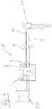
- FIG. 1 A pump device 1 according to the invention for use in operating theaters is shown schematically.
- the pump device 1 comprises a pump unit 2 with a pump 3 and a control unit 4.
- the pump 3 can be controlled via the control unit 4.
- control elements (not shown) can also be present on the pump unit 2, via which the pump unit 2 can be actuated.
- the desired flow rate of pump 3 can be set via a corresponding control element.
- the controls and any control lines are not shown.
- a pump hose 5 is connected to the pump unit 2, so that fluids can be conveyed through the pump hose 5 by the pump 3 of the pump unit 2.
- the pump 3 can, for example, convey rinsing liquid from a reservoir (not shown) through the pump hose 5, so that the rinsing liquid emerges at the free end 6 of the pump hose 5. It is also possible for the pump 3 of the pump unit 2 to work in the opposite direction, so that a fluid is sucked in at the free end 6 of the pump hose 5 and conveyed through the pump hose 5 into a collecting container (not shown).
- a light source 7 is also provided on the pump unit 2.
- the light source 7 can be controlled by the control unit 4 with regard to its switched-on state and its intensity.
- the light source 7 can comprise a single illuminant, for example a light emitting diode (LED).
- LED light emitting diode
- the control unit 4 is designed to control the color or color changes of the light source 7.
- An optical fiber 8 is provided along the pump hose 5.
- the first end of the optical fiber 8 is arranged such that the light from the light source 7 is coupled into the optical fiber 8.
- the light coupled into the optical fiber 8 at the first end 9 emerges again at the second end 10 of the optical fiber 8 and is perceptible there as a point of light.
- the second end 10 of the optical fiber 8 is arranged at the free end 6 of the pump hose 5, more precisely 5 cm from the free end 6 of the pump hose 5.
- the control unit 4 is designed to control the light source 7 as a function of the operating state of the pump unit 2 and in particular the pump 3.
- the light source 7 can be switched on and off in parallel with the on and off state of the pump 3.
- the control unit 4 can control the light source 7 in such a way that the light source 7 pulsates or flashes as a function of the flow rate set on the pump 3.
- the free end 6 of the pump hose 5 in pump devices 1 for operating theaters, as shown in Figure 1 is shown, is routed regularly into or at least close to the actual operation area, and the second end 10 of the optical fiber 8 is arranged at this free end 6 of the pump hose 5, the operator receives the corresponding information in the form of a light point at the second end 10 of the Optical fiber 8 in his field of vision. Because of the corresponding coupling from the light source 7, the light point reproduces information about the operating state of the pump unit 2.
- FIG. 2 A second embodiment of a pump device 1 according to the invention is shown, which largely consists of that Figure 1 corresponds. In the following, therefore, only the differences of the exemplary embodiment according to FIG Figure 2 towards that one Figure 1 received. For the rest, reference is made to the above statements
- the optical fiber 8 is not led to the free end 6 of the pump hose 5. Rather, the second end 10 of the optical fiber is set back 30 cm from the free end 6 of the pump hose 5.
- the optical fiber 8 has a plurality of impurities 11 between its first end 9 and its second end 10, the impurities 11 being designed to emit light. A part of the light coupled in at the first end 9 thus emerges at the defects 11, with the result that each defect 11 is perceptible to the operator as a single point of light. As a result, the surgeon can perceive a plurality of light points along the pump tube 5, each of which indicates the operating state of the pump unit 2.
- the optical fiber 8 arranged on the outside of the wall 12 of the pump hose 5 comprises a light-guiding core 13 which is surrounded by a jacket 14.
- the cladding 14 has a lower refractive index than the light-guiding core 13, so that there is basically total reflection at the transition from the core 13 to the cladding 14.
- the optical fiber 8 is notched in the area of the defects 11, so that the jacket 14 is interrupted. As a result, there is no longer any total reflection at the notches. Rather, light can emerge from the light-guiding core 13 in the region of the defect 11. This light emission can be perceived by the surgeon as a point of light at the fault point 11.
- the distance between two adjacent defects 11 decreases from the first end 9 of the optical fiber to the second end 10 of the optical fiber.
- the distance between the two defects 11 closest to the pump unit 2 is greatest, the distance between the two defects 11 closest to the second end 10 of the optical fiber 8 is smallest.
- This measure makes it possible for approximately the same amount of light to be emitted per length section of the tube 5.
- the person skilled in the art is readily able to appropriately select the required individual distances between two adjacent defects 11 in order to obtain an essentially identical intensity at all defects 11.
- the second end 10 of the optical fiber 3 is in accordance with the exemplary embodiment Figure 2 free and is therefore also perceptible to the surgeon as a point of light.
- the pump unit 2 in the exemplary embodiment according to Figure 2 furthermore has a temperature sensor 15 with which the temperature of the fluid conveyed through the pump hose 5 is measured.
- the control unit 4 is designed such that the color of the light source 7 is changed in accordance with the measured values of the temperature sensor 15. For example, the color of the light source 7 can be green if the measured temperature is in a predetermined temperature range. If the measured temperature lies outside this temperature range, the color of the light source 7 can be changed to red.
- the optical fiber 8 is arranged on the outside of the pump hose 5.
- the optical fiber 8 can be subsequently glued onto the pump hose 5.
- the pump hose 5 is designed as a multi-lumen tube, the optical fiber 8 being guided through a chamber of the multi-lumen tube.
- the pump hose 5 is transparent at least at the points at which light emerges from the optical fiber 8 - that is to say at the second end 10 and / or the fault points 11.
- optical fibers for endoscopic lighting or laser applications etc. can be guided through the other chambers of the multi-lumen tube.
- the optical fiber 8 can be coextruded with the multi-lumen tube or subsequently inserted into an already existing multi-lumen tube.
- FIG 4 An arrangement according to the invention comprising a pump device 1 and an endoscope 20 is shown.
- the pump device 1 corresponds to that Figure 1 , which is why reference is made to the explanations there.
- the endoscope 20 has a supply channel for rinsing liquid, with which a cavity to be examined can be filled and rinsed.
- Corresponding endoscopes are known from the prior art.
- the pump device 1 is designed with a corresponding arrangement for supplying rinsing liquid from a reservoir 21.
- the operating state of the pump unit 2 of the pump device 1 is indicated to the operator by the light point at the second end 10 of the optical fiber 8, which is arranged close to the endoscope 20 due to its arrangement at the end 6 of the pump tube 5 (cf. Figure 1 ).
- the surgeon thus receives information about the operating state of the pump unit 2 in the immediate vicinity of the operating area, so that he can perceive this information casually and without effort.
Landscapes
- Health & Medical Sciences (AREA)
- Life Sciences & Earth Sciences (AREA)
- Surgery (AREA)
- Optics & Photonics (AREA)
- Physics & Mathematics (AREA)
- Biomedical Technology (AREA)
- Medical Informatics (AREA)
- Radiology & Medical Imaging (AREA)
- Nuclear Medicine, Radiotherapy & Molecular Imaging (AREA)
- Engineering & Computer Science (AREA)
- Biophysics (AREA)
- Heart & Thoracic Surgery (AREA)
- Pathology (AREA)
- Molecular Biology (AREA)
- Animal Behavior & Ethology (AREA)
- General Health & Medical Sciences (AREA)
- Public Health (AREA)
- Veterinary Medicine (AREA)
- Endoscopes (AREA)
- Instruments For Viewing The Inside Of Hollow Bodies (AREA)
Applications Claiming Priority (2)
| Application Number | Priority Date | Filing Date | Title |
|---|---|---|---|
| DE102014204997.0A DE102014204997B4 (de) | 2014-03-18 | 2014-03-18 | Pumpenvorrichtung |
| PCT/EP2015/054755 WO2015139972A1 (de) | 2014-03-18 | 2015-03-06 | Pumpenvorrichtung |
Publications (2)
| Publication Number | Publication Date |
|---|---|
| EP3119262A1 EP3119262A1 (de) | 2017-01-25 |
| EP3119262B1 true EP3119262B1 (de) | 2020-07-15 |
Family
ID=52682685
Family Applications (1)
| Application Number | Title | Priority Date | Filing Date |
|---|---|---|---|
| EP15709877.3A Not-in-force EP3119262B1 (de) | 2014-03-18 | 2015-03-06 | Pumpenvorrichtung |
Country Status (6)
| Country | Link |
|---|---|
| US (1) | US10772484B2 (enExample) |
| EP (1) | EP3119262B1 (enExample) |
| JP (1) | JP6475747B2 (enExample) |
| CN (1) | CN106413505B (enExample) |
| DE (1) | DE102014204997B4 (enExample) |
| WO (1) | WO2015139972A1 (enExample) |
Families Citing this family (3)
| Publication number | Priority date | Publication date | Assignee | Title |
|---|---|---|---|---|
| CN107610688B (zh) * | 2017-09-05 | 2024-04-26 | 同济大学 | 一种腔管复合隔声结构 |
| CN112535769A (zh) * | 2020-11-05 | 2021-03-23 | 李明 | 一种肿瘤科用引流装置 |
| DE102022106156A1 (de) * | 2022-03-16 | 2023-09-21 | Schölly Fiberoptic GmbH | Medizinisches Visualisierungs- und/oder Beleuchtungssystem sowie Verfahren zum Anzeigen eines nicht-sichtbaren Beleuchtungslichts |
Family Cites Families (15)
| Publication number | Priority date | Publication date | Assignee | Title |
|---|---|---|---|---|
| US4416268A (en) * | 1980-07-10 | 1983-11-22 | Olympus Optical Co., Ltd. | Endoscope having two detachable armour tubes |
| JPS5846930A (ja) * | 1981-09-17 | 1983-03-18 | オリンパス光学工業株式会社 | 内視鏡の送気送液装置 |
| US4813400A (en) * | 1986-08-08 | 1989-03-21 | Olympus Optical Co., Ltd. | Optical fiber assembly for an endoscope |
| US5432876C1 (en) * | 1992-10-19 | 2002-05-21 | Minnesota Mining & Mfg | Illumination devices and optical fibres for use therein |
| US6929602B2 (en) * | 1998-09-28 | 2005-08-16 | Kabushiki Kaisha Toshiba | Endoscope apparatus |
| JP2004524076A (ja) * | 2001-01-11 | 2004-08-12 | ギブン・イメージング・リミテツド | 生体内処置のための装置およびシステム |
| JP5302491B2 (ja) * | 2003-12-22 | 2013-10-02 | 日亜化学工業株式会社 | 発光装置及び内視鏡装置 |
| JP4716689B2 (ja) * | 2004-08-04 | 2011-07-06 | オリンパス株式会社 | 内視鏡システム |
| DE102009024941A1 (de) * | 2009-06-09 | 2010-12-23 | Carl Zeiss Surgical Gmbh | Beleuchtungsvorrichtung und medizinisch-optisches Beobachtungsgerät |
| JP5542021B2 (ja) * | 2010-09-28 | 2014-07-09 | 富士フイルム株式会社 | 内視鏡システム、内視鏡システムの作動方法、及びプログラム |
| CN103249351A (zh) * | 2010-12-08 | 2013-08-14 | 内布拉斯加大学董事会 | 便携式腹腔镜系统 |
| DE102012207053A1 (de) * | 2012-04-27 | 2013-10-31 | Abiomed Europe Gmbh | Intravasale rotationsblutpumpe |
| CN202876062U (zh) * | 2012-04-28 | 2013-04-17 | 黄新奎 | 一种多功能负压吸引器 |
| EP3566636B1 (en) * | 2012-06-13 | 2024-02-21 | Boston Scientific Scimed, Inc. | Medical device visualization system |
| JP5650697B2 (ja) * | 2012-09-06 | 2015-01-07 | 富士フイルム株式会社 | 送気システム |
-
2014
- 2014-03-18 DE DE102014204997.0A patent/DE102014204997B4/de not_active Expired - Fee Related
-
2015
- 2015-03-06 US US15/119,228 patent/US10772484B2/en not_active Expired - Fee Related
- 2015-03-06 EP EP15709877.3A patent/EP3119262B1/de not_active Not-in-force
- 2015-03-06 CN CN201580011438.2A patent/CN106413505B/zh not_active Expired - Fee Related
- 2015-03-06 WO PCT/EP2015/054755 patent/WO2015139972A1/de not_active Ceased
- 2015-03-06 JP JP2016550848A patent/JP6475747B2/ja not_active Expired - Fee Related
Non-Patent Citations (1)
| Title |
|---|
| None * |
Also Published As
| Publication number | Publication date |
|---|---|
| WO2015139972A1 (de) | 2015-09-24 |
| EP3119262A1 (de) | 2017-01-25 |
| US20170007099A1 (en) | 2017-01-12 |
| CN106413505A (zh) | 2017-02-15 |
| DE102014204997A1 (de) | 2015-09-24 |
| CN106413505B (zh) | 2019-07-16 |
| JP6475747B2 (ja) | 2019-02-27 |
| DE102014204997B4 (de) | 2016-08-18 |
| JP2017509385A (ja) | 2017-04-06 |
| US10772484B2 (en) | 2020-09-15 |
Similar Documents
| Publication | Publication Date | Title |
|---|---|---|
| EP3119262B1 (de) | Pumpenvorrichtung | |
| EP3747348A1 (de) | Lichtquelle und system für die und verfahren zur fluoreszenzdiagnose | |
| DE102009008427A1 (de) | Endoskop | |
| EP3205361B1 (de) | Maschine zur extrakorporalen blutbehandlung mit lichtgebender einrichtung | |
| EP3142898B1 (de) | Elektronische baugruppe zum beleuchten eines einen detektionsbereich eines sensors markierenden zielbereiches | |
| DE202008017921U1 (de) | Operationsleuchte mit beleuchteten Handgriffen | |
| DE102005005984B4 (de) | Fluoreszenz-/Infraroteinrichtung für Operationsmikroskope | |
| DE10013666A1 (de) | Gerät zum Eingeben und Anzeigen von Soll- bzw. Grenzwerten | |
| DE10242607B4 (de) | Endoskop mit Lichtleiterbündel | |
| DE4012545C2 (de) | Chirurgie-Handgriff mit einer Aufnahme für eine aktive Elektrode | |
| EP3796356A1 (de) | Fussschalter für medizinische geräte | |
| DE10238171A1 (de) | LED-Wasserstrahldüse | |
| DE202009001741U1 (de) | Endoskop | |
| DE102010022784A1 (de) | Schutzanzug mit Atemluftversorgungseinrichtung | |
| DE102007018863B4 (de) | Vorrichtung für die gleichzeitige Vakuummassage und Farbbestrahlung | |
| DE102014101455B4 (de) | Beleuchtungseinheit und Saugerspitze für minimalinvasive Operationen mit wahlweise beleuchtbaren Markierungen | |
| DE102012214171A1 (de) | Medizinisches Gerät | |
| DE3706943A1 (de) | Beleuchtungseinrichtung fuer ein zahnaerztliches handinstrument | |
| DE202005011205U1 (de) | Brunnenleuchte | |
| DE10359501A1 (de) | Zahnärztliches Funktionshandstück mit Lichtabgabeelement | |
| EP0173816A2 (de) | Vorrichtung zum Bespülen und Absaugen bei der Endoskopie | |
| WO2025172164A1 (de) | Medizinische vorrichtung | |
| DE102006011749A1 (de) | Verfahren und Vorrichtung zur fotodynamischen Diagnose von biologischem Gewebe | |
| DE102011106524A1 (de) | Lichtleitrohr aus Verbundmaterial | |
| DE202006009608U1 (de) | Medizinisches Endoskop mit Lichtquelle |
Legal Events
| Date | Code | Title | Description |
|---|---|---|---|
| STAA | Information on the status of an ep patent application or granted ep patent |
Free format text: STATUS: THE INTERNATIONAL PUBLICATION HAS BEEN MADE |
|
| PUAI | Public reference made under article 153(3) epc to a published international application that has entered the european phase |
Free format text: ORIGINAL CODE: 0009012 |
|
| STAA | Information on the status of an ep patent application or granted ep patent |
Free format text: STATUS: REQUEST FOR EXAMINATION WAS MADE |
|
| 17P | Request for examination filed |
Effective date: 20161018 |
|
| AK | Designated contracting states |
Kind code of ref document: A1 Designated state(s): AL AT BE BG CH CY CZ DE DK EE ES FI FR GB GR HR HU IE IS IT LI LT LU LV MC MK MT NL NO PL PT RO RS SE SI SK SM TR |
|
| AX | Request for extension of the european patent |
Extension state: BA ME |
|
| DAV | Request for validation of the european patent (deleted) | ||
| DAX | Request for extension of the european patent (deleted) | ||
| GRAP | Despatch of communication of intention to grant a patent |
Free format text: ORIGINAL CODE: EPIDOSNIGR1 |
|
| STAA | Information on the status of an ep patent application or granted ep patent |
Free format text: STATUS: GRANT OF PATENT IS INTENDED |
|
| INTG | Intention to grant announced |
Effective date: 20200219 |
|
| GRAS | Grant fee paid |
Free format text: ORIGINAL CODE: EPIDOSNIGR3 |
|
| GRAA | (expected) grant |
Free format text: ORIGINAL CODE: 0009210 |
|
| STAA | Information on the status of an ep patent application or granted ep patent |
Free format text: STATUS: THE PATENT HAS BEEN GRANTED |
|
| AK | Designated contracting states |
Kind code of ref document: B1 Designated state(s): AL AT BE BG CH CY CZ DE DK EE ES FI FR GB GR HR HU IE IS IT LI LT LU LV MC MK MT NL NO PL PT RO RS SE SI SK SM TR |
|
| REG | Reference to a national code |
Ref country code: CH Ref legal event code: EP Ref country code: GB Ref legal event code: FG4D Free format text: NOT ENGLISH |
|
| REG | Reference to a national code |
Ref country code: IE Ref legal event code: FG4D Free format text: LANGUAGE OF EP DOCUMENT: GERMAN |
|
| REG | Reference to a national code |
Ref country code: DE Ref legal event code: R096 Ref document number: 502015013012 Country of ref document: DE |
|
| REG | Reference to a national code |
Ref country code: AT Ref legal event code: REF Ref document number: 1290035 Country of ref document: AT Kind code of ref document: T Effective date: 20200815 |
|
| REG | Reference to a national code |
Ref country code: LT Ref legal event code: MG4D |
|
| REG | Reference to a national code |
Ref country code: NL Ref legal event code: MP Effective date: 20200715 |
|
| PG25 | Lapsed in a contracting state [announced via postgrant information from national office to epo] |
Ref country code: FI Free format text: LAPSE BECAUSE OF FAILURE TO SUBMIT A TRANSLATION OF THE DESCRIPTION OR TO PAY THE FEE WITHIN THE PRESCRIBED TIME-LIMIT Effective date: 20200715 Ref country code: LT Free format text: LAPSE BECAUSE OF FAILURE TO SUBMIT A TRANSLATION OF THE DESCRIPTION OR TO PAY THE FEE WITHIN THE PRESCRIBED TIME-LIMIT Effective date: 20200715 Ref country code: HR Free format text: LAPSE BECAUSE OF FAILURE TO SUBMIT A TRANSLATION OF THE DESCRIPTION OR TO PAY THE FEE WITHIN THE PRESCRIBED TIME-LIMIT Effective date: 20200715 Ref country code: SE Free format text: LAPSE BECAUSE OF FAILURE TO SUBMIT A TRANSLATION OF THE DESCRIPTION OR TO PAY THE FEE WITHIN THE PRESCRIBED TIME-LIMIT Effective date: 20200715 Ref country code: NO Free format text: LAPSE BECAUSE OF FAILURE TO SUBMIT A TRANSLATION OF THE DESCRIPTION OR TO PAY THE FEE WITHIN THE PRESCRIBED TIME-LIMIT Effective date: 20201015 Ref country code: BG Free format text: LAPSE BECAUSE OF FAILURE TO SUBMIT A TRANSLATION OF THE DESCRIPTION OR TO PAY THE FEE WITHIN THE PRESCRIBED TIME-LIMIT Effective date: 20201015 Ref country code: GR Free format text: LAPSE BECAUSE OF FAILURE TO SUBMIT A TRANSLATION OF THE DESCRIPTION OR TO PAY THE FEE WITHIN THE PRESCRIBED TIME-LIMIT Effective date: 20201016 Ref country code: ES Free format text: LAPSE BECAUSE OF FAILURE TO SUBMIT A TRANSLATION OF THE DESCRIPTION OR TO PAY THE FEE WITHIN THE PRESCRIBED TIME-LIMIT Effective date: 20200715 Ref country code: PT Free format text: LAPSE BECAUSE OF FAILURE TO SUBMIT A TRANSLATION OF THE DESCRIPTION OR TO PAY THE FEE WITHIN THE PRESCRIBED TIME-LIMIT Effective date: 20201116 |
|
| PG25 | Lapsed in a contracting state [announced via postgrant information from national office to epo] |
Ref country code: PL Free format text: LAPSE BECAUSE OF FAILURE TO SUBMIT A TRANSLATION OF THE DESCRIPTION OR TO PAY THE FEE WITHIN THE PRESCRIBED TIME-LIMIT Effective date: 20200715 Ref country code: RS Free format text: LAPSE BECAUSE OF FAILURE TO SUBMIT A TRANSLATION OF THE DESCRIPTION OR TO PAY THE FEE WITHIN THE PRESCRIBED TIME-LIMIT Effective date: 20200715 Ref country code: LV Free format text: LAPSE BECAUSE OF FAILURE TO SUBMIT A TRANSLATION OF THE DESCRIPTION OR TO PAY THE FEE WITHIN THE PRESCRIBED TIME-LIMIT Effective date: 20200715 Ref country code: IS Free format text: LAPSE BECAUSE OF FAILURE TO SUBMIT A TRANSLATION OF THE DESCRIPTION OR TO PAY THE FEE WITHIN THE PRESCRIBED TIME-LIMIT Effective date: 20201115 |
|
| PG25 | Lapsed in a contracting state [announced via postgrant information from national office to epo] |
Ref country code: NL Free format text: LAPSE BECAUSE OF FAILURE TO SUBMIT A TRANSLATION OF THE DESCRIPTION OR TO PAY THE FEE WITHIN THE PRESCRIBED TIME-LIMIT Effective date: 20200715 |
|
| REG | Reference to a national code |
Ref country code: DE Ref legal event code: R097 Ref document number: 502015013012 Country of ref document: DE |
|
| PG25 | Lapsed in a contracting state [announced via postgrant information from national office to epo] |
Ref country code: IT Free format text: LAPSE BECAUSE OF FAILURE TO SUBMIT A TRANSLATION OF THE DESCRIPTION OR TO PAY THE FEE WITHIN THE PRESCRIBED TIME-LIMIT Effective date: 20200715 Ref country code: DK Free format text: LAPSE BECAUSE OF FAILURE TO SUBMIT A TRANSLATION OF THE DESCRIPTION OR TO PAY THE FEE WITHIN THE PRESCRIBED TIME-LIMIT Effective date: 20200715 Ref country code: CZ Free format text: LAPSE BECAUSE OF FAILURE TO SUBMIT A TRANSLATION OF THE DESCRIPTION OR TO PAY THE FEE WITHIN THE PRESCRIBED TIME-LIMIT Effective date: 20200715 Ref country code: SM Free format text: LAPSE BECAUSE OF FAILURE TO SUBMIT A TRANSLATION OF THE DESCRIPTION OR TO PAY THE FEE WITHIN THE PRESCRIBED TIME-LIMIT Effective date: 20200715 Ref country code: RO Free format text: LAPSE BECAUSE OF FAILURE TO SUBMIT A TRANSLATION OF THE DESCRIPTION OR TO PAY THE FEE WITHIN THE PRESCRIBED TIME-LIMIT Effective date: 20200715 Ref country code: EE Free format text: LAPSE BECAUSE OF FAILURE TO SUBMIT A TRANSLATION OF THE DESCRIPTION OR TO PAY THE FEE WITHIN THE PRESCRIBED TIME-LIMIT Effective date: 20200715 |
|
| PLBE | No opposition filed within time limit |
Free format text: ORIGINAL CODE: 0009261 |
|
| STAA | Information on the status of an ep patent application or granted ep patent |
Free format text: STATUS: NO OPPOSITION FILED WITHIN TIME LIMIT |
|
| PG25 | Lapsed in a contracting state [announced via postgrant information from national office to epo] |
Ref country code: AL Free format text: LAPSE BECAUSE OF FAILURE TO SUBMIT A TRANSLATION OF THE DESCRIPTION OR TO PAY THE FEE WITHIN THE PRESCRIBED TIME-LIMIT Effective date: 20200715 |
|
| 26N | No opposition filed |
Effective date: 20210416 |
|
| PG25 | Lapsed in a contracting state [announced via postgrant information from national office to epo] |
Ref country code: SK Free format text: LAPSE BECAUSE OF FAILURE TO SUBMIT A TRANSLATION OF THE DESCRIPTION OR TO PAY THE FEE WITHIN THE PRESCRIBED TIME-LIMIT Effective date: 20200715 |
|
| PG25 | Lapsed in a contracting state [announced via postgrant information from national office to epo] |
Ref country code: SI Free format text: LAPSE BECAUSE OF FAILURE TO SUBMIT A TRANSLATION OF THE DESCRIPTION OR TO PAY THE FEE WITHIN THE PRESCRIBED TIME-LIMIT Effective date: 20200715 |
|
| PG25 | Lapsed in a contracting state [announced via postgrant information from national office to epo] |
Ref country code: MC Free format text: LAPSE BECAUSE OF FAILURE TO SUBMIT A TRANSLATION OF THE DESCRIPTION OR TO PAY THE FEE WITHIN THE PRESCRIBED TIME-LIMIT Effective date: 20200715 |
|
| REG | Reference to a national code |
Ref country code: CH Ref legal event code: PL |
|
| GBPC | Gb: european patent ceased through non-payment of renewal fee |
Effective date: 20210306 |
|
| REG | Reference to a national code |
Ref country code: BE Ref legal event code: MM Effective date: 20210331 |
|
| PG25 | Lapsed in a contracting state [announced via postgrant information from national office to epo] |
Ref country code: GB Free format text: LAPSE BECAUSE OF NON-PAYMENT OF DUE FEES Effective date: 20210306 Ref country code: FR Free format text: LAPSE BECAUSE OF NON-PAYMENT OF DUE FEES Effective date: 20210331 Ref country code: IE Free format text: LAPSE BECAUSE OF NON-PAYMENT OF DUE FEES Effective date: 20210306 Ref country code: CH Free format text: LAPSE BECAUSE OF NON-PAYMENT OF DUE FEES Effective date: 20210331 Ref country code: LU Free format text: LAPSE BECAUSE OF NON-PAYMENT OF DUE FEES Effective date: 20210306 Ref country code: LI Free format text: LAPSE BECAUSE OF NON-PAYMENT OF DUE FEES Effective date: 20210331 |
|
| REG | Reference to a national code |
Ref country code: AT Ref legal event code: MM01 Ref document number: 1290035 Country of ref document: AT Kind code of ref document: T Effective date: 20210306 |
|
| PG25 | Lapsed in a contracting state [announced via postgrant information from national office to epo] |
Ref country code: BE Free format text: LAPSE BECAUSE OF NON-PAYMENT OF DUE FEES Effective date: 20210331 |
|
| PG25 | Lapsed in a contracting state [announced via postgrant information from national office to epo] |
Ref country code: AT Free format text: LAPSE BECAUSE OF NON-PAYMENT OF DUE FEES Effective date: 20210306 |
|
| PG25 | Lapsed in a contracting state [announced via postgrant information from national office to epo] |
Ref country code: HU Free format text: LAPSE BECAUSE OF FAILURE TO SUBMIT A TRANSLATION OF THE DESCRIPTION OR TO PAY THE FEE WITHIN THE PRESCRIBED TIME-LIMIT; INVALID AB INITIO Effective date: 20150306 |
|
| PGFP | Annual fee paid to national office [announced via postgrant information from national office to epo] |
Ref country code: DE Payment date: 20230321 Year of fee payment: 9 |
|
| P01 | Opt-out of the competence of the unified patent court (upc) registered |
Effective date: 20230516 |
|
| PG25 | Lapsed in a contracting state [announced via postgrant information from national office to epo] |
Ref country code: CY Free format text: LAPSE BECAUSE OF FAILURE TO SUBMIT A TRANSLATION OF THE DESCRIPTION OR TO PAY THE FEE WITHIN THE PRESCRIBED TIME-LIMIT Effective date: 20200715 |
|
| PG25 | Lapsed in a contracting state [announced via postgrant information from national office to epo] |
Ref country code: MK Free format text: LAPSE BECAUSE OF FAILURE TO SUBMIT A TRANSLATION OF THE DESCRIPTION OR TO PAY THE FEE WITHIN THE PRESCRIBED TIME-LIMIT Effective date: 20200715 |
|
| PG25 | Lapsed in a contracting state [announced via postgrant information from national office to epo] |
Ref country code: TR Free format text: LAPSE BECAUSE OF FAILURE TO SUBMIT A TRANSLATION OF THE DESCRIPTION OR TO PAY THE FEE WITHIN THE PRESCRIBED TIME-LIMIT Effective date: 20200715 |
|
| PG25 | Lapsed in a contracting state [announced via postgrant information from national office to epo] |
Ref country code: MT Free format text: LAPSE BECAUSE OF FAILURE TO SUBMIT A TRANSLATION OF THE DESCRIPTION OR TO PAY THE FEE WITHIN THE PRESCRIBED TIME-LIMIT Effective date: 20200715 |
|
| REG | Reference to a national code |
Ref country code: DE Ref legal event code: R119 Ref document number: 502015013012 Country of ref document: DE |
|
| PG25 | Lapsed in a contracting state [announced via postgrant information from national office to epo] |
Ref country code: DE Free format text: LAPSE BECAUSE OF NON-PAYMENT OF DUE FEES Effective date: 20241001 |
|
| PG25 | Lapsed in a contracting state [announced via postgrant information from national office to epo] |
Ref country code: DE Free format text: LAPSE BECAUSE OF NON-PAYMENT OF DUE FEES Effective date: 20241001 |